EP3768558B1 - Système de capteurs pour un véhicule et procédé de contrôle d'un capteur - Google Patents
Système de capteurs pour un véhicule et procédé de contrôle d'un capteur Download PDFInfo
- Publication number
- EP3768558B1 EP3768558B1 EP19712919.0A EP19712919A EP3768558B1 EP 3768558 B1 EP3768558 B1 EP 3768558B1 EP 19712919 A EP19712919 A EP 19712919A EP 3768558 B1 EP3768558 B1 EP 3768558B1
- Authority
- EP
- European Patent Office
- Prior art keywords
- sensor
- signal
- thd
- threshold value
- value
- Prior art date
- Legal status (The legal status is an assumption and is not a legal conclusion. Google has not performed a legal analysis and makes no representation as to the accuracy of the status listed.)
- Active
Links
- 238000012544 monitoring process Methods 0.000 title claims description 20
- 238000000034 method Methods 0.000 title claims description 16
- 238000011156 evaluation Methods 0.000 claims description 27
- 230000006870 function Effects 0.000 claims description 22
- 230000002950 deficient Effects 0.000 claims description 20
- 230000007547 defect Effects 0.000 claims description 12
- 238000001914 filtration Methods 0.000 claims description 9
- 238000009434 installation Methods 0.000 claims description 9
- 230000015572 biosynthetic process Effects 0.000 claims description 6
- 230000008569 process Effects 0.000 claims description 2
- 238000001514 detection method Methods 0.000 description 14
- 230000001133 acceleration Effects 0.000 description 12
- 238000012545 processing Methods 0.000 description 7
- 230000009467 reduction Effects 0.000 description 6
- 230000006399 behavior Effects 0.000 description 4
- 230000010354 integration Effects 0.000 description 4
- 230000008901 benefit Effects 0.000 description 3
- 238000005259 measurement Methods 0.000 description 3
- 230000008859 change Effects 0.000 description 2
- 238000004422 calculation algorithm Methods 0.000 description 1
- 238000004364 calculation method Methods 0.000 description 1
- 238000004891 communication Methods 0.000 description 1
- 238000004590 computer program Methods 0.000 description 1
- 230000009849 deactivation Effects 0.000 description 1
- 230000001419 dependent effect Effects 0.000 description 1
- 238000011161 development Methods 0.000 description 1
- 230000018109 developmental process Effects 0.000 description 1
- 238000010586 diagram Methods 0.000 description 1
- 230000000694 effects Effects 0.000 description 1
- 238000005516 engineering process Methods 0.000 description 1
- 230000003287 optical effect Effects 0.000 description 1
- 230000010355 oscillation Effects 0.000 description 1
- 230000002093 peripheral effect Effects 0.000 description 1
- 238000007781 pre-processing Methods 0.000 description 1
- 238000012797 qualification Methods 0.000 description 1
- 239000004065 semiconductor Substances 0.000 description 1
- 230000001550 time effect Effects 0.000 description 1
- 238000012549 training Methods 0.000 description 1
- 238000002604 ultrasonography Methods 0.000 description 1
Images
Classifications
-
- B—PERFORMING OPERATIONS; TRANSPORTING
- B60—VEHICLES IN GENERAL
- B60W—CONJOINT CONTROL OF VEHICLE SUB-UNITS OF DIFFERENT TYPE OR DIFFERENT FUNCTION; CONTROL SYSTEMS SPECIALLY ADAPTED FOR HYBRID VEHICLES; ROAD VEHICLE DRIVE CONTROL SYSTEMS FOR PURPOSES NOT RELATED TO THE CONTROL OF A PARTICULAR SUB-UNIT
- B60W50/00—Details of control systems for road vehicle drive control not related to the control of a particular sub-unit, e.g. process diagnostic or vehicle driver interfaces
- B60W50/02—Ensuring safety in case of control system failures, e.g. by diagnosing, circumventing or fixing failures
- B60W50/0205—Diagnosing or detecting failures; Failure detection models
-
- B—PERFORMING OPERATIONS; TRANSPORTING
- B60—VEHICLES IN GENERAL
- B60R—VEHICLES, VEHICLE FITTINGS, OR VEHICLE PARTS, NOT OTHERWISE PROVIDED FOR
- B60R21/00—Arrangements or fittings on vehicles for protecting or preventing injuries to occupants or pedestrians in case of accidents or other traffic risks
- B60R21/01—Electrical circuits for triggering passive safety arrangements, e.g. airbags, safety belt tighteners, in case of vehicle accidents or impending vehicle accidents
- B60R21/013—Electrical circuits for triggering passive safety arrangements, e.g. airbags, safety belt tighteners, in case of vehicle accidents or impending vehicle accidents including means for detecting collisions, impending collisions or roll-over
- B60R21/0136—Electrical circuits for triggering passive safety arrangements, e.g. airbags, safety belt tighteners, in case of vehicle accidents or impending vehicle accidents including means for detecting collisions, impending collisions or roll-over responsive to actual contact with an obstacle, e.g. to vehicle deformation, bumper displacement or bumper velocity relative to the vehicle
-
- G—PHYSICS
- G07—CHECKING-DEVICES
- G07C—TIME OR ATTENDANCE REGISTERS; REGISTERING OR INDICATING THE WORKING OF MACHINES; GENERATING RANDOM NUMBERS; VOTING OR LOTTERY APPARATUS; ARRANGEMENTS, SYSTEMS OR APPARATUS FOR CHECKING NOT PROVIDED FOR ELSEWHERE
- G07C5/00—Registering or indicating the working of vehicles
- G07C5/08—Registering or indicating performance data other than driving, working, idle, or waiting time, with or without registering driving, working, idle or waiting time
- G07C5/0808—Diagnosing performance data
-
- B—PERFORMING OPERATIONS; TRANSPORTING
- B60—VEHICLES IN GENERAL
- B60R—VEHICLES, VEHICLE FITTINGS, OR VEHICLE PARTS, NOT OTHERWISE PROVIDED FOR
- B60R21/00—Arrangements or fittings on vehicles for protecting or preventing injuries to occupants or pedestrians in case of accidents or other traffic risks
- B60R21/01—Electrical circuits for triggering passive safety arrangements, e.g. airbags, safety belt tighteners, in case of vehicle accidents or impending vehicle accidents
- B60R2021/01013—Means for detecting collision, impending collision or roll-over
- B60R2021/01027—Safing sensors
-
- B—PERFORMING OPERATIONS; TRANSPORTING
- B60—VEHICLES IN GENERAL
- B60R—VEHICLES, VEHICLE FITTINGS, OR VEHICLE PARTS, NOT OTHERWISE PROVIDED FOR
- B60R21/00—Arrangements or fittings on vehicles for protecting or preventing injuries to occupants or pedestrians in case of accidents or other traffic risks
- B60R21/01—Electrical circuits for triggering passive safety arrangements, e.g. airbags, safety belt tighteners, in case of vehicle accidents or impending vehicle accidents
- B60R2021/01122—Prevention of malfunction
- B60R2021/01184—Fault detection or diagnostic circuits
- B60R2021/0119—Plausibility check
-
- B—PERFORMING OPERATIONS; TRANSPORTING
- B60—VEHICLES IN GENERAL
- B60W—CONJOINT CONTROL OF VEHICLE SUB-UNITS OF DIFFERENT TYPE OR DIFFERENT FUNCTION; CONTROL SYSTEMS SPECIALLY ADAPTED FOR HYBRID VEHICLES; ROAD VEHICLE DRIVE CONTROL SYSTEMS FOR PURPOSES NOT RELATED TO THE CONTROL OF A PARTICULAR SUB-UNIT
- B60W50/00—Details of control systems for road vehicle drive control not related to the control of a particular sub-unit, e.g. process diagnostic or vehicle driver interfaces
- B60W50/02—Ensuring safety in case of control system failures, e.g. by diagnosing, circumventing or fixing failures
- B60W50/0205—Diagnosing or detecting failures; Failure detection models
- B60W2050/021—Means for detecting failure or malfunction
-
- B—PERFORMING OPERATIONS; TRANSPORTING
- B60—VEHICLES IN GENERAL
- B60W—CONJOINT CONTROL OF VEHICLE SUB-UNITS OF DIFFERENT TYPE OR DIFFERENT FUNCTION; CONTROL SYSTEMS SPECIALLY ADAPTED FOR HYBRID VEHICLES; ROAD VEHICLE DRIVE CONTROL SYSTEMS FOR PURPOSES NOT RELATED TO THE CONTROL OF A PARTICULAR SUB-UNIT
- B60W50/00—Details of control systems for road vehicle drive control not related to the control of a particular sub-unit, e.g. process diagnostic or vehicle driver interfaces
- B60W50/02—Ensuring safety in case of control system failures, e.g. by diagnosing, circumventing or fixing failures
- B60W50/0205—Diagnosing or detecting failures; Failure detection models
- B60W2050/0215—Sensor drifts or sensor failures
Definitions
- the invention is based on a sensor arrangement for a vehicle according to the generic type of independent patent claim 1.
- the subject matter of the present invention is also a method for monitoring a sensor.
- the detection of vehicle crashes in airbag control units is generally based on information from sensors installed in the vehicle, which are designed, for example, as acceleration and/or pressure sensors.
- the signals measured by these sensors are suitably processed (eg filtered/integrated) and compared to triggering thresholds in order to arrive at a triggering decision.
- a plausibility concept can be used that requires a second independent sensor to also output signal values that are significantly above the signal values for normal driving situations indicates. Triggering is released only if the triggering decision of the main sensor is present together with the plausibility decision of the independent sensor. However, such a plausibility concept alone does not adequately protect against false tripping.
- the plausibility sensor Over the lifetime of the vehicle, situations such as driving over curbs with sufficiently high acceleration signals can occur in which the plausibility sensor reaches a plausibility decision. If a triggering decision were to be made permanently due to a defective main sensor, the risk of false triggering would be far too high. For this reason, the plausibility concept only provides the time for the sensor monitoring so that they can detect a defective sensor and this can then be deactivated.
- Methods for monitoring sensors are known from the prior art, which monitor the sensor hardware itself and typically run in the sensor itself in the initialization phase after power-on. For example, the sensor can be deflected in a targeted manner and it can then be checked whether the sensor signal returns cleanly to "zero" after the deflection has ceased. Furthermore, the communication between the sensor and the airbag control unit can be monitored for Manchester errors, for example. In addition, monitoring can be carried out in the airbag control unit, which checks the output sensor signal for certain implausible properties. This includes, for example, offset monitoring and/or step or gradient monitoring. A faulty offset is characterized, for example, by a high signal amplitude, which occurs over a long period of time and corresponds to an unphysical, high reduction in speed. A step or gradient error is characterized, for example, by the sensor value changing more strongly from one measured value to the next than the filter curve of the sensor allows.
- the sensor arrangement for a vehicle with the features of independent patent claim 1 and the method for monitoring a sensor with the features of independent patent claim 11 have the advantage that sensor signal errors above a certain level are independent of the exact signal form, such as offset, jump, individual peaks, any oscillations can be recognized as defective.
- the exact form of the sensor error signal plays no role above a certain minimum strength.
- a hypothetical sensor error signal from a defective sensor which is exactly the same as a crash signal, can also be recognized as an error by comparing it with sensor signals from other intact sensors.
- an intact sensor measures a high acceleration or pressure signal that has its origin in a crash or an extreme driving maneuver such as driving over a curb
- other sensors in the vehicle will also measure this event, so that there is no sensor error.
- the high sensor signal has its origin in a sensor error
- the other sensors only measure weak signals in the range of normal driving situations, so that a sensor error can be concluded.
- the signal values during normal driving operation are on the order of 1 g, for example.
- Embodiments of the invention advantageously reduce the risk of false triggering due to the coincidence of an as yet undiscovered sensor error with a plausibility decision caused by a severe driving maneuver.
- Embodiments of the present invention provide a sensor arrangement for a vehicle, with a first sensor, which detects at least one crash-relevant physical quantity and outputs at least one corresponding first sensor signal, and with at least one second sensor, which independently of the first sensor detects at least one crash-relevant physical quantity and outputs at least one corresponding second sensor signal, and is available with an evaluation and control unit which receives the at least one first sensor signal and the at least one second sensor signal and evaluates it for crash detection.
- the evaluation and control unit uses at least one second comparison signal, which is based on the at least one second sensor signal of the at least one second sensor, in order to monitor the first sensor, with the evaluation and control unit recognizing that the first sensor is defective if at least a first comparison signal, which is based on the first sensor signal, has a high signal value which is above a predetermined first threshold value, and the at least one second comparison signal from the second sensor used to monitor the first sensor simultaneously has a low signal value, which is below a predetermined second threshold value, and/or a deviation function generated from the first comparison signal and the second comparison signal is above a predetermined third threshold value.
- a method for monitoring a sensor which detects at least one physical variable relevant to a crash and outputs at least one corresponding first sensor signal, the at least one first sensor signal being evaluated for crash detection.
- at least one second sensor signal recorded for crash detection from at least one additional independent sensor is evaluated in order to detect a defect in the sensor, a defect in the sensor being detected if at least a first comparison signal, which is based on the first sensor signal, has a high signal value, which is above a predetermined first threshold value, and at least one second comparison signal used to monitor the sensor, which is based on the at least one second sensor signal of the additional sensor, simultaneously has a low signal value, which is below a predetermined second threshold value, and/or an off the deviation function generated by the first comparison signal and the second comparison signal is above a predetermined third threshold value.
- the at least one first comparison signal can, for example, correspond to the at least one first sensor signal and/or at least one processed first sensor signal.
- the at least one second comparison signal can, for example, correspond to the at least one second sensor signal and/or at least one processed second sensor signal.
- the evaluation and control unit is understood to be an electrical device, such as a control device, in particular an airbag control device, which processes or evaluates sensor signals detected by sensors.
- the evaluation and control unit can have at least one interface, which can be in the form of hardware and/or software.
- the interfaces can be part of a so-called system ASIC, for example, which contains a wide variety of functions of the evaluation and control unit.
- the interfaces can be separate integrated circuits or to consist at least partially of discrete components.
- the interfaces can be software modules which are present, for example, on a microcontroller alongside other software modules.
- a computer program product with program code is also advantageous, which is stored on a machine-readable medium such as a semiconductor memory, a hard disk memory or an optical memory and is used to carry out the evaluation when the program is executed by the evaluation and control unit.
- a sensor is understood to mean an assembly which comprises at least one sensor element which directly or indirectly detects a physical variable or a change in a physical variable and preferably converts it into an electrical sensor signal.
- the sensor can include, for example, pressure-sensitive sensor elements, which determine an impact area on the vehicle, and/or acceleration sensor elements, which record acceleration-relevant information from the vehicle, and/or sensor elements, which determine objects and/or obstacles and/or other crash-relevant vehicle environment data and make them available for evaluation put.
- sensor elements can be based, for example, on video and/or radar and/or lidar and/or PMD and/or ultrasound technologies.
- signals and information from an existing ABS sensor system and the variables derived in the control unit provided for this purpose can also be evaluated.
- the evaluation and control unit can calculate an absolute value function of the sensor signals, with the evaluation and control unit for processing the sensor signals or the calculated absolute value functions can carry out filtering and/or window integral formation and/or integral formation.
- filtering There are countless possibilities for signal processing.
- a certain filtering will be used for the first sensor signal, since one does not want to qualify an error on a single high sensor value.
- the first sensor signal or the absolute value of the sensor signal can be filtered, window-integrated or integrated.
- the absolute amount has the advantage that even strongly oscillating error signals lead to high processed first sensor signals.
- the integration can be started when the first sensor signal exceeds a start threshold.
- the integrated value can be fed back or reset when the first sensor signal again falls below a reset threshold, which can be identical to the start threshold.
- the first threshold value can represent a signal value which is significantly above the signal values for a normal driving situation.
- the second threshold value can have an upper limit on a range of signal values for a normal driving situation. A triggering-critical sensor error of the first sensor to be monitored can thus be recognized by the fact that the sensor to be monitored measures high signal values which are significantly above normal driving situations, while the second sensors used for monitoring simultaneously measure low signal values in the range of normal driving situations.
- the first sensor and the at least one second sensor can detect the same physical variable.
- the first sensor and the at least one second sensor can detect different physical quantities.
- the first sensor and the at least one second sensor can have the same detection direction or different detection directions.
- the first sensor and the at least one second sensor can be arranged at the same installation location or at different installation locations.
- the evaluation and control unit can deactivate a first sensor which has been identified as defective. This significantly reduces the risk of false triggering due to the coincidence of an as yet undiscovered sensor error with a plausibility decision caused by a severe driving maneuver.
- the first sensor signal and/or the processed first sensor signal for defect detection can be above the first threshold value for a specified minimum period of time, while the second sensor signal and/or the processed second sensor signal for a specified time period which Minimum period of time for the first sensor signal and / or the processed first sensor signal overlaps, below the second threshold.
- the first sensor signal and/or the processed first sensor signal can be identified as possibly defective if they are above the first threshold value for a predetermined minimum period of time. This can prevent one-time and short-term incorrect measurements from leading to a deactivation of the sensor.
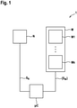
- FIG. 1 shows a schematic block diagram of an exemplary embodiment of a sensor arrangement according to the invention for a vehicle.
- the illustrated exemplary embodiment of a sensor arrangement 1 according to the invention for a vehicle 1 comprises a first sensor N, which detects at least one physical variable relevant to a crash and outputs at least one corresponding first sensor signal S N , at least one second sensor M, which is independent of the first sensor N at least detects a crash-relevant physical variable and outputs at least one corresponding second sensor signal S M , and an evaluation and control unit ⁇ C, which receives the at least one first sensor signal S N and the at least one second sensor signal S M and evaluates it for crash detection.
- the evaluation and control unit ⁇ C uses at least one second comparison signal, which is based on the at least one second sensor signal S M of the at least one second sensor M, in order to monitor the first sensor N.
- the evaluation and control unit ⁇ C recognizes that the first sensor N is defective if at least one first comparison signal, which is based on the at least one first sensor signal S N , has a high signal value, which is above a predetermined first threshold value Thd_det, and the Monitoring of the first sensor N used at least one second comparison signal, which at the same time has a low signal value on the at least one second sensor signal S M of the second sensor M, which is below a predetermined second threshold value Thd_drive.
- the evaluation and control unit ⁇ C recognizes that the first sensor N is defective if a deviation function f(S N , ⁇ S M ⁇ ) generated from the first comparison signal and the second comparison signal is above a predetermined third threshold value Thd.
- the at least one first comparison signal can correspond to the at least one first sensor signal S N and/or at least one processed first sensor signal (g(S N )).
- the at least one second comparison signal can correspond to the at least one second sensor signal S M and/or at least one processed second sensor signal h M (S M ).
- a triggering-critical sensor error of the first sensor N can thus be recognized by the fact that the first sensor N to be monitored measures high signal values S N significantly above normal driving situations, and the sensors ⁇ M ⁇ (M ⁇ N) used for monitoring measure low signal values S M im at the same time Have area normal driving situations.
- a sensor error in the first sensor N can therefore be detected using the sensor signals ⁇ S M ⁇ if a deviation function f(S N , ⁇ S M ⁇ ) evaluating the respective sensor signals is above a third threshold value Thd, as can be seen from inequality (1) is evident.
- the evaluation and control unit ⁇ C deactivates a first sensor N recognized as defective.
- the concept can be used in different expansion stages.
- first sensor N there are further sensors ⁇ M ⁇ at the same installation location in a vehicle in addition to the first sensor N to be monitored.
- the airbag control unit in which several acceleration sensors, which measure, for example, in the longitudinal and lateral direction, and optionally yaw rate sensors, which measure a yaw rate about the longitudinal axis or vertical axis, for example, are usually available.
- second sensor signals S M are also always measured by the further sensors ⁇ M ⁇ . This often also applies when they measure a different physical quantity.
- the first sensor N can measure a longitudinal acceleration
- the at least one second sensor M can measure a lateral acceleration or a rate of rotation about the longitudinal axis.
- the sensors in the airbag control unit are redundant in order to implement the plausibility concept described in the prior art, so that in addition to the main sensor or the first sensor N, there is also a second acceleration sensor or a second sensor M with the same measuring direction and very similar sensor properties such as measuring range, Resolution, filter behavior is present.
- the at least one second sensor M is not directly comparable with the first sensor N, for example due to a different detection direction or due to different sensor properties, in which case no actual signal deviation of the two sensor signals S N , S M can be evaluated.
- the at least one Sensor M is represented by a set of second sensors ⁇ M ⁇ , which includes k second sensors M1, ..., Mk.
- Embodiments of the sensor arrangement 1 for a vehicle detect a sensor error through high signal values at the first sensor N and low signal values at the second sensors ⁇ M ⁇ . Particularly advantageously, it is not the raw sensor signals S N and ⁇ S M ⁇ that are used for this comparison, but suitably processed sensor signals g(S N ) and ⁇ h M (S M ) ⁇ .
- g denotes the signal processing function of the first sensor signal N
- h M denotes the signal processing function of the at least one second sensor M, which can generally be different for each second sensor M.
- a trigger-critical sensor error of the first sensor N is detected when the processed first signal g(S N ) exceeds the predetermined first threshold value Thd_det and the processed second sensor signals ⁇ h M (S M ) ⁇ are below the second threshold value Thd_drive.
- the processed sensor signal ⁇ h M (S M ) ⁇ of each sensor M must be below a corresponding sensor-specific second threshold value.
- the set of processed signals ⁇ h M (S M ) ⁇ can also be combined into a single processed signal H( ⁇ S M ⁇ ), for example by selecting a maximum. The query is then simplified to two threshold value comparisons.
- a first deviation function corresponds to f(S N , ⁇ S M ⁇ ), which the evaluation and control unit ⁇ C uses to calculate the at least one first sensor signal S N and the at least one second sensor signal S M or the at least one processed first Evaluate sensor signal g(S N ) and the at least one processed second sensor signal h M (S M ), a Boolean function. Equation (1) then becomes Equation (2).
- f S N S M G S N > Thd_Det & H S M ⁇ thd_drive
- the signal processing functions g and h There are countless possibilities for the signal processing functions g and h. As a rule, a certain filtering will be used for the first processed sensor signal g(S N ), since one does not want to qualify an error based on a single high sensor value.
- the absolute value has the advantage that strongly oscillating error signals also lead to high processed first sensor signals g(S N ).
- the integration can be started when the sensor signal S N exceeds a start threshold Thd_start.
- the integrated value can then be fed back or reset when the sensor signal S N again falls below a reset threshold Thd_reset, which can be identical to the start threshold Thd_start.
- the functions h M can be set similarly. Typically, however, only weak filtering or no filtering at all is carried out here, since a sufficiently high signal value at one of the second sensors ⁇ M ⁇ is already an indication that a real driving situation is involved. This applies all the more if the second sensors ⁇ M ⁇ do not measure the same physical variable as the first sensor N to be monitored.
- a redundant sensor system which means that the sensors N, M measure the same physical variable, such as a longitudinal acceleration.
- a real driving situation or a crash should lead to a physical measured value of the sensors N, M that is comparable within the scope of the tolerances, ie the deviation between the sensors N, M can be evaluated directly.
- a second sensor M which is redundant to the first sensor N, will be present here.
- a similar situation also exists with a pressure hose sensor, which can be used to detect a pedestrian impact.
- a pressure hose is integrated in the vehicle front end, which is on both sides of a pressure sensor is completed. An impact deforms the hose and leads to an increase in pressure on both pressure sensors.
- the pressure signals at the two sensors differ somewhat from one another (e.g. due to transit time effects), but are always of a similar magnitude.
- the sensor signals S N , S M are compared directly with one another in the second exemplary embodiment, it is advantageous to minimize any slight differences in the measuring range or filter behavior or the influence of sensor noise by means of suitable pre-processing, eg signal limitation or weak pre-filtering.
- a deviation measure k(S N -S M ) can then be calculated directly. Again, an error or defect in the first sensor N is only recognized if there is a significant deviation, possibly over a longer period of time. For this purpose, it is advisable to measure the signal difference S N -S M between the first sensor signal S N and the second sensor signal S M or the absolute value of the signal difference
- the integrated value can be fed back or reset when the reset threshold Thd_reset, which can be identical to the start threshold, is undershot again. If you want to limit the calculation of the deviation measure k to "normal driving situations" and exclude conceivable larger deviations in a crash, a condition according to inequality (3) can also be used as the starting condition for filtering or summing up the difference signal.
- S N > Thd 1 & S M ⁇ Thd 2 be used, the threshold values Thd1 and Thd2 being above the values of the first sensor signal S N and the second sensor signal S M that can be achieved during normal driving and a first threshold value Thd1 being significantly above the second threshold value Thd2 in order to avoid a sufficient deviation ensure.
- Summing up is then only carried out if the monitoring sensor or the second sensor M measures a value within the framework of normal driving and the sensor to be monitored or the first sensor N sees values outside of normal driving due to a sensor error.
- the accumulated value can then be fed back or reset as soon as one of the two conditions is no longer met. It is also particularly advantageous not to evaluate the filtered or integrated signal difference absolutely but rather relatively, for example in relation to a similarly filtered or integrated first sensor signal S N .
- Equation (1) Equation (4).
- a sensor error is then recognized by the AND combination of three criteria.
- a high (processed) first sensor signal S N of the first sensor N (g(SN) > Thd_det).
- a small (processed) second sensor signal S M of the second sensor M (h(S M ) ⁇ Thd_drive) and a large signal deviation between sensors N and M (k(S N - S M ) > Thd).
- equation (1) becomes equation (5) and the deviation function is described by a Boolean function with a threshold value of zero.
- f S N S M G S N > Thd_Det & H S M ⁇ thd_drive & k S N ⁇ S M > Thd > 0
- the general detection concept for sensor errors in the first sensor N is then that the processed first sensor signal g(S N ) is for a predetermined minimum period of time [t; t+Tmin] is above the first threshold value Thd_det, and the processed second sensor signal h M (S M ) is in a predetermined time range [t-T1; t+T2], which is the minimum period of time [t; t+Tmin] is below the second threshold Thd_drive.
- the optional minimum period of time Tmin can mask a brief exceeding of the threshold value of the first threshold value Thd_det by the first sensor signal g(S N ) in a local misuse event, such as a hammer blow.
- the two optional time spans T1 and T2 take into account the different time behavior at different measurement locations. This means that a sensor error or defect in the first sensor N is present and detected when the processed sensor signal g(S N ) of the first sensor N is above the first threshold value Thd_det for a sufficiently long time, and the other sensors M in the vehicle are in a certain period of time before and after the first sensor N exceeds this threshold value, no significant signals are measured, ie only signals in the normal driving range are measured.
- Embodiments of the method according to the invention for monitoring a sensor N which detects at least one physical variable relevant to a crash and outputs at least one corresponding first sensor signal S N , with the at least one first sensor signal S N being evaluated for crash detection, evaluate at least one second sensor signal S M detected for crash detection at least one additional independent sensor M to detect a defect in the sensor N.
- a defect in the sensor N is detected if at least one first comparison signal, which is based on the first sensor signal S N , has a high signal value which is above a predetermined first threshold value Thd_det, and at least one second comparison signal used to monitor the sensor N, which is based on the at least one second sensor signal S M of the further sensor M, at the same time has a low signal value which is below a predetermined second threshold value Thd_drive.
- a defect in the sensor N is detected when one of the first comparison signal and deviation function f(S N , ⁇ S M ⁇ ) generated from the second comparison signal is above a predetermined third threshold value Thd.
- the at least one first comparison signal can correspond to the at least one first sensor signal S N and/or at least one processed first sensor signal (g(S N )), and the at least one second comparison signal can correspond to the at least one second sensor signal S M and/or correspond to at least one processed second sensor signal h M (S M ).
- the first threshold value Thd_det represents a signal value which is significantly above signal values for a normal driving situation.
- the second threshold value Thd_drive has an upper limit on a range of signal values for a normal driving situation.
- Embodiments of the present invention identify a defective sensor as defective and deactivate the sensor identified as defective if a second sensor does not confirm the signals of the first sensor.
Claims (16)
- Agencement de capteurs (1) pour un véhicule, comprenant un premier capteur (N) qui détecte au moins une grandeur physique pertinente en cas de collision et délivre au moins un premier signal de capteur correspondant (SN), et au moins un deuxième capteur (M) qui détecte indépendamment du premier capteur (N) au moins une grandeur physique pertinente en cas de collision et délivre au moins un deuxième signal de capteur correspondant (SM), et une unité d'évaluation et de commande (µC) qui reçoit ledit au moins un premier signal de capteur (SN) et ledit au moins un deuxième signal de capteur (SM) et l'évalue pour une reconnaissance de collision,
caractérisé en ce que l'unité d'évaluation et de commande (µC) utilise au moins un deuxième signal de comparaison qui est basé sur ledit au moins un deuxième signal de capteur (SM) du au moins un deuxième capteur (M) pour surveiller le premier capteur (N), l'unité d'évaluation et de commande (µC) reconnaissant que le premier capteur (N) est défectueux si au moins un premier signal de comparaison qui est basé sur ledit au moins un premier signal de capteur (SN) présente une valeur de signal élevée qui est située au-dessus d'une première valeur seuil prédéfinie (Thd_det), et ledit au moins un deuxième signal de comparaison du deuxième capteur (M) utilisé pour la surveillance du premier capteur (N) présente en même temps une valeur de signal faible qui est située au-dessous d'une deuxième valeur seuil prédéfinie (Thd_drive), et/ou une fonction d'écart (f(SN, {SM})) produite à partir du premier signal de comparaison et du deuxième signal de comparaison se situe au-dessus d'une troisième valeur seuil prédéfinie (Thd) . - Agencement de capteurs (1) selon la revendication 1, caractérisé en ce que ledit au moins un premier signal de comparaison correspond audit au moins un premier signal de capteur (SN) et/ou à au moins un premier signal de capteur traité (g(SN)), et ledit au moins un deuxième signal de comparaison correspond audit au moins un deuxième signal de capteur (SM) et/ou à au moins un deuxième signal de capteur traité (hM(SM)).
- Agencement de capteurs (1) selon la revendication 2, caractérisé en ce que l'unité d'évaluation et de commande (µC) calcule respectivement une fonction de valeur absolue des signaux de capteur (SN, SM), l'unité d'évaluation et de commande (µC) effectuant pour le traitement des signaux de capteur (SN, SM) ou des fonctions de valeur absolue calculées un filtrage et/ou une formation d'intégrale de fenêtre et/ou une formation d'intégrale.
- Agencement de capteurs (1) selon la revendication 3, caractérisé en ce que l'unité d'évaluation et de commande (µC) démarre la formation d'intégrale lorsque le signal correspondant dépasse un seuil de démarrage (Thd_start), l'unité d'évaluation et de commande (µC) terminant la formation d'intégrale et réinitialisant la valeur d'intégrale lorsque le signal correspondant soupasse un seuil de réinitialisation (Thd_reset).
- Agencement de capteurs (1) selon l'une quelconque des revendications 1 à 4, caractérisé en ce que la première valeur seuil (Thd_det) représente une valeur de signal qui est située nettement au-dessus de valeurs de signal pour une situation de conduite normale, la deuxième valeur seuil (Thd_drive) délimitant vers le haut une plage de valeurs de signal pour une situation de conduite normale.
- Agencement de capteurs (1) selon l'une quelconque des revendications 1 à 5, caractérisé en ce que le premier capteur (N) et ledit au moins un deuxième capteur (M) détectent la même grandeur physique.
- Agencement de capteurs (1) selon l'une quelconque des revendications 1 à 5, caractérisé en ce que le premier capteur (N) et ledit au moins un deuxième capteur (M) détectent différentes grandeurs physiques.
- Agencement de capteurs (1) selon l'une quelconque des revendications 1 à 7, caractérisé en ce que le premier capteur (N) et ledit au moins un deuxième capteur (M) présentent la même direction de détection ou des directions de détection différentes.
- Agencement de capteurs (1) selon l'une quelconque des revendications 1 à 8, caractérisé en ce que le premier capteur (N) et ledit au moins un deuxième capteur (M) sont disposés au même site d'installation ou à différents sites d'installation.
- Agencement de capteurs (1) selon l'une quelconque des revendications 1 à 9, caractérisé en ce que l'unité d'évaluation et de commande (µC) désactive un premier capteur (N) reconnu comme défectueux.
- Procédé de surveillance d'un capteur (N) qui détecte au moins une grandeur physique pertinente en cas de collision et délivre au moins un premier signal de capteur (SN) correspondant, ledit au moins un premier signal de capteur (SN) étant évalué pour la reconnaissance de collision, au moins un deuxième signal de capteur (SM) détecté pour la reconnaissance de collision d'au moins un autre capteur indépendant (M) étant évalué pour reconnaître un défaut du capteur (N), un défaut du capteur (N) étant reconnu quand au moins un premier signal de comparaison qui est basé sur ledit au moins un premier signal de capteur (SN) présente une valeur de signal élevée qui est située au-dessus d'une première valeur seuil prédéfinie (Thd_det), et au moins un deuxième signal de comparaison utilisé pour surveiller le capteur (N) et qui est basé sur ledit au moins un deuxième signal de capteur (SM) de l'autre capteur (M) présente en même temps une valeur de signal faible qui est située au-dessous d'une deuxième valeur de seuil prédéfinie (Thd_drive), et/ou une fonction d'écart (f(SN, {SM})) produite à partir du premier signal de comparaison et du deuxième signal de comparaison se situe au-dessus d'une troisième valeur seuil prédéfinie (Thd) .
- Procédé selon la revendication 11, caractérisé en ce que ledit au moins un premier signal de comparaison correspond audit au moins un premier signal de capteur (SN) et/ou à au moins un premier capteur signal traité (g(SN)), et ledit au moins un deuxième signal de comparaison correspond audit au moins un deuxième signal de capteur (SM) et/ou à au moins un deuxième signal de capteur traité (hM(SM)).
- Procédé selon la revendication 11 ou 12, caractérisé en ce que le premier signal de capteur (SN) et/ou le premier signal de capteur traité (g(SN)) pour la reconnaissance de défaut se situent pour une période minimale prédéfinie (Tmin) au-dessus de la première valeur seuil (Thd_det) alors que le deuxième signal de capteur (SM) et/ou le deuxième signal de capteur traité (hM (SM)) se situent au-dessous de la deuxième valeur seuil (Thd_det) pour une plage de temps prédéfinie qui recouvre la période minimale (Tmin) pour le premier signal de capteur (SN) et/ou le premier signal de capteur traité (g(SN)).
- Procédé selon l'une quelconque des revendications 11 à 13, caractérisé en ce que la première valeur seuil (Thd_det) représente une valeur de signal qui se situe nettement au-dessus des valeurs de signal pour une situation de conduite normale, la deuxième valeur seuil (Thd -drive) délimitant vers le haut une plage de valeurs de signal pour une situation de conduite normale.
- Procédé selon l'une quelconque des revendications 11 à 14, caractérisé en ce que le premier capteur (N) et ledit au moins un deuxième capteur (M) détectent la même grandeur physique et présentent la même direction de détection.
- Procédé selon l'une quelconque des revendications 11 à 15, caractérisé en ce qu'un premier capteur (N) reconnu comme défectueux est désactivé.
Applications Claiming Priority (2)
| Application Number | Priority Date | Filing Date | Title |
|---|---|---|---|
| DE102018204286.1A DE102018204286A1 (de) | 2018-03-21 | 2018-03-21 | Sensoranordnung für ein Fahrzeug und Verfahren zur Überwachung eines Sensors |
| PCT/EP2019/056235 WO2019179840A2 (fr) | 2018-03-21 | 2019-03-13 | Système de capteurs pour un véhicule et procédé de contrôle d'un capteur |
Publications (2)
| Publication Number | Publication Date |
|---|---|
| EP3768558A2 EP3768558A2 (fr) | 2021-01-27 |
| EP3768558B1 true EP3768558B1 (fr) | 2022-02-09 |
Family
ID=65904370
Family Applications (1)
| Application Number | Title | Priority Date | Filing Date |
|---|---|---|---|
| EP19712919.0A Active EP3768558B1 (fr) | 2018-03-21 | 2019-03-13 | Système de capteurs pour un véhicule et procédé de contrôle d'un capteur |
Country Status (6)
| Country | Link |
|---|---|
| US (1) | US11358604B2 (fr) |
| EP (1) | EP3768558B1 (fr) |
| JP (1) | JP7045476B2 (fr) |
| CN (1) | CN111757823B (fr) |
| DE (1) | DE102018204286A1 (fr) |
| WO (1) | WO2019179840A2 (fr) |
Families Citing this family (3)
| Publication number | Priority date | Publication date | Assignee | Title |
|---|---|---|---|---|
| DE102019207365A1 (de) * | 2019-05-20 | 2020-11-26 | Robert Bosch Gmbh | Verfahren und Vorrichtung zum Bereitstellen eines Betriebszustands eines Sensors eines Fahrzeugs |
| CN113110349B (zh) * | 2021-04-27 | 2022-03-25 | 湖南省水利投地方电力有限公司 | 一种水电站水轮发电机组显控装置 |
| EP4234354A1 (fr) | 2022-02-23 | 2023-08-30 | KNORR-BREMSE Systeme für Nutzfahrzeuge GmbH | Procédé de plausibilisation d'un taux de rotation d'une carrosserie d'un véhicule et dispositif de mise en uvre du procédé |
Family Cites Families (16)
| Publication number | Priority date | Publication date | Assignee | Title |
|---|---|---|---|---|
| JP3426295B2 (ja) * | 1992-09-25 | 2003-07-14 | ローベルト ボツシユ ゲゼルシヤフト ミツト ベシユレンクテル ハフツング | 電子装置を検査する方法および装置 |
| KR20010101502A (ko) * | 1999-01-12 | 2001-11-14 | 칼 하인쯔 호르닝어 | 차량의 승객 보호를 위한 제어 시스템의 기능 점검을 위한방법 |
| US7625006B2 (en) * | 2001-04-09 | 2009-12-01 | Trw Automotive U.S. Llc | Method and apparatus for controlling an actuatable restraining device using crush zone sensors for safing function |
| DE10164083A1 (de) * | 2001-12-24 | 2003-07-10 | Hella Kg Hueck & Co | Verfahren zur Überprüfung einer automatischen Ansteuerung einer Beleuchtungseinrichtung eines Fahrzeuges und Prüfeinrichtung |
| JP4020084B2 (ja) | 2004-02-19 | 2007-12-12 | 日産自動車株式会社 | 衝突予測装置 |
| JP4601524B2 (ja) | 2005-09-06 | 2010-12-22 | 富士通テン株式会社 | エアバッグ装置 |
| US8095276B2 (en) * | 2008-10-15 | 2012-01-10 | Autoliv Asp, Inc. | Sensor system including a confirmation sensor for detecting an impending collision |
| DE102011075545A1 (de) * | 2011-05-10 | 2012-11-15 | Robert Bosch Gmbh | Verfahren und Vorrichtung zur Überprüfung eines Sensorsignals und zur Ansteuerung eines Insassenschutzmittels eines Fahrzeugs |
| DE102011084784A1 (de) * | 2011-10-19 | 2013-04-25 | Robert Bosch Gmbh | Verfahren zur Plausibilisierung von Sensorsignalen sowie Verfahren und Vorrichtung zur Ausgabe eines Auslösesignals |
| DE102012222690A1 (de) | 2012-12-11 | 2014-06-12 | Robert Bosch Gmbh | Redundante Sensorauswertung eines Mehrachsen-Sensors |
| CN103344271B (zh) * | 2013-07-22 | 2015-12-23 | 中国航空动力机械研究所 | 传感器故障诊断装置和方法以及传感器的信号采集系统 |
| DE102015216494A1 (de) * | 2015-08-28 | 2017-03-02 | Robert Bosch Gmbh | Verfahren und Vorrichtung zur Erkennung wenigstens einer Sensorfunktion wenigstens eines ersten Sensor wenigstens eines ersten Fahrzeugs |
| JP2017075844A (ja) * | 2015-10-14 | 2017-04-20 | 株式会社デンソー | 複合センサ |
| DE102016105016A1 (de) | 2016-03-17 | 2017-09-21 | Trw Automotive Gmbh | Verfahren zur Erkennung eines Ausfalls eines Sensors einer Fahrzeugsicherheitseinrichtung |
| JP6872420B2 (ja) * | 2017-05-23 | 2021-05-19 | 本田技研工業株式会社 | 車載装置 |
| US11163303B2 (en) * | 2018-02-13 | 2021-11-02 | Nvidia Corporation | Sharing sensor data between multiple controllers to support vehicle operations |
-
2018
- 2018-03-21 DE DE102018204286.1A patent/DE102018204286A1/de active Pending
-
2019
- 2019-03-13 US US16/771,208 patent/US11358604B2/en active Active
- 2019-03-13 EP EP19712919.0A patent/EP3768558B1/fr active Active
- 2019-03-13 CN CN201980014839.1A patent/CN111757823B/zh active Active
- 2019-03-13 WO PCT/EP2019/056235 patent/WO2019179840A2/fr unknown
- 2019-03-13 JP JP2020550738A patent/JP7045476B2/ja active Active
Also Published As
| Publication number | Publication date |
|---|---|
| CN111757823A (zh) | 2020-10-09 |
| US11358604B2 (en) | 2022-06-14 |
| WO2019179840A2 (fr) | 2019-09-26 |
| CN111757823B (zh) | 2023-02-03 |
| US20200369287A1 (en) | 2020-11-26 |
| WO2019179840A3 (fr) | 2020-04-09 |
| JP7045476B2 (ja) | 2022-03-31 |
| JP2021518304A (ja) | 2021-08-02 |
| DE102018204286A1 (de) | 2019-09-26 |
| EP3768558A2 (fr) | 2021-01-27 |
Similar Documents
| Publication | Publication Date | Title |
|---|---|---|
| EP3768558B1 (fr) | Système de capteurs pour un véhicule et procédé de contrôle d'un capteur | |
| EP2769184B1 (fr) | Contrôle de plausibilité d'un signal de capteur | |
| DE112012006407B4 (de) | Vorrichtung und Verfahren zum Detektieren eines Fahrzeug/Fußgängeraufpralls | |
| DE102009002682B4 (de) | Einrichtung und Verfahren zur Residuenauswertung eines Residuums zur Erkennung von Systemfehlern im Systemverhalten eines Systems eines Flugzeugs | |
| DE102017107877A1 (de) | Erkennung und Rekonstruktion eines Neigungsratensensorfehlers | |
| EP2079990A1 (fr) | Procédé et dispositif pour contrôler le signal d'un capteur | |
| EP2339364A2 (fr) | Alignment mutuel de capteur automobile en azimut | |
| DE102011121822A1 (de) | Verfahren und Einrichtung zum Bestimmen der Einbaulage eines Sensormoduls in einem Fahrzeug sowie Fahrzeug mit einer derartigen Einrichtung | |
| DE102017107596A1 (de) | Erkennung und rekonstruktion eines aufhängungshöhensensorfehlers | |
| DE102016105016A1 (de) | Verfahren zur Erkennung eines Ausfalls eines Sensors einer Fahrzeugsicherheitseinrichtung | |
| DE3916046A1 (de) | Antiblockierregler oder antriebsschlupfregler | |
| DE10217031A1 (de) | Hochdynamisches Normalkraft- und Dehnungsmessgerät auf der Basis piezoelektrischer Sensoren | |
| DE102018214831A1 (de) | Verfahren zur Erkennung einer Degradation eines abstandsmessenden Systems | |
| DE102021004103A1 (de) | Verfahren und Anordnung zur Überwachung und Detektion von Sensorfehlern in Inertial-Mess-Systemen | |
| DE10242128B4 (de) | Verfahren und Vorrichtung zur Überwachung einer redundanten Sensoranordnung | |
| DE102008061924A1 (de) | Sensoranordnung, Tachographenanordnung und Verfahren zur Erkennung einer Manipulation | |
| DE102014211178A1 (de) | Verfahren und System zur Korrektur von Messdaten eines ersten Sensorsystems | |
| EP2544935B1 (fr) | Procédé et dispositif de détection d'un écart d'un signal de vitesse de rotation d'un capteur de vitesse de rotation | |
| WO2009138293A1 (fr) | Procédé et organe de commande de moyens de protection des personnes pour un véhicule | |
| DE102004044335A1 (de) | Verfahren zum Überwachen von redundanten Sensorsignalen | |
| DE10333323B4 (de) | Verfahren zur Ausfallerkennung von Sensoren, insbesondere für ein ESP System für Fahrzeuge | |
| DE102012101296A1 (de) | Aufprallsensorsystem mit zumindest einem Drucksensor | |
| DE102006040653A1 (de) | Vorrichtung und Verfahren zur Detektion eines Fußgängeraufpralls | |
| WO2020224971A1 (fr) | Procédé de détermination de valeurs de mesure au moyen d'au moins deux procédés de mesure différents et son utilisation | |
| DE10225212B4 (de) | System zur Erfassung eines Sensorfehlers |
Legal Events
| Date | Code | Title | Description |
|---|---|---|---|
| STAA | Information on the status of an ep patent application or granted ep patent |
Free format text: STATUS: UNKNOWN |
|
| STAA | Information on the status of an ep patent application or granted ep patent |
Free format text: STATUS: THE INTERNATIONAL PUBLICATION HAS BEEN MADE |
|
| PUAI | Public reference made under article 153(3) epc to a published international application that has entered the european phase |
Free format text: ORIGINAL CODE: 0009012 |
|
| STAA | Information on the status of an ep patent application or granted ep patent |
Free format text: STATUS: REQUEST FOR EXAMINATION WAS MADE |
|
| 17P | Request for examination filed |
Effective date: 20201021 |
|
| AK | Designated contracting states |
Kind code of ref document: A2 Designated state(s): AL AT BE BG CH CY CZ DE DK EE ES FI FR GB GR HR HU IE IS IT LI LT LU LV MC MK MT NL NO PL PT RO RS SE SI SK SM TR |
|
| AX | Request for extension of the european patent |
Extension state: BA ME |
|
| DAV | Request for validation of the european patent (deleted) | ||
| DAX | Request for extension of the european patent (deleted) | ||
| GRAP | Despatch of communication of intention to grant a patent |
Free format text: ORIGINAL CODE: EPIDOSNIGR1 |
|
| STAA | Information on the status of an ep patent application or granted ep patent |
Free format text: STATUS: GRANT OF PATENT IS INTENDED |
|
| INTG | Intention to grant announced |
Effective date: 20211117 |
|
| GRAS | Grant fee paid |
Free format text: ORIGINAL CODE: EPIDOSNIGR3 |
|
| GRAA | (expected) grant |
Free format text: ORIGINAL CODE: 0009210 |
|
| STAA | Information on the status of an ep patent application or granted ep patent |
Free format text: STATUS: THE PATENT HAS BEEN GRANTED |
|
| AK | Designated contracting states |
Kind code of ref document: B1 Designated state(s): AL AT BE BG CH CY CZ DE DK EE ES FI FR GB GR HR HU IE IS IT LI LT LU LV MC MK MT NL NO PL PT RO RS SE SI SK SM TR |
|
| REG | Reference to a national code |
Ref country code: GB Ref legal event code: FG4D Free format text: NOT ENGLISH |
|
| REG | Reference to a national code |
Ref country code: CH Ref legal event code: EP Ref country code: AT Ref legal event code: REF Ref document number: 1467303 Country of ref document: AT Kind code of ref document: T Effective date: 20220215 |
|
| REG | Reference to a national code |
Ref country code: IE Ref legal event code: FG4D Free format text: LANGUAGE OF EP DOCUMENT: GERMAN |
|
| REG | Reference to a national code |
Ref country code: DE Ref legal event code: R096 Ref document number: 502019003408 Country of ref document: DE |
|
| REG | Reference to a national code |
Ref country code: SE Ref legal event code: TRGR |
|
| REG | Reference to a national code |
Ref country code: LT Ref legal event code: MG9D |
|
| REG | Reference to a national code |
Ref country code: NL Ref legal event code: MP Effective date: 20220209 |
|
| PG25 | Lapsed in a contracting state [announced via postgrant information from national office to epo] |
Ref country code: RS Free format text: LAPSE BECAUSE OF FAILURE TO SUBMIT A TRANSLATION OF THE DESCRIPTION OR TO PAY THE FEE WITHIN THE PRESCRIBED TIME-LIMIT Effective date: 20220209 Ref country code: PT Free format text: LAPSE BECAUSE OF FAILURE TO SUBMIT A TRANSLATION OF THE DESCRIPTION OR TO PAY THE FEE WITHIN THE PRESCRIBED TIME-LIMIT Effective date: 20220609 Ref country code: NO Free format text: LAPSE BECAUSE OF FAILURE TO SUBMIT A TRANSLATION OF THE DESCRIPTION OR TO PAY THE FEE WITHIN THE PRESCRIBED TIME-LIMIT Effective date: 20220509 Ref country code: NL Free format text: LAPSE BECAUSE OF FAILURE TO SUBMIT A TRANSLATION OF THE DESCRIPTION OR TO PAY THE FEE WITHIN THE PRESCRIBED TIME-LIMIT Effective date: 20220209 Ref country code: LT Free format text: LAPSE BECAUSE OF FAILURE TO SUBMIT A TRANSLATION OF THE DESCRIPTION OR TO PAY THE FEE WITHIN THE PRESCRIBED TIME-LIMIT Effective date: 20220209 Ref country code: HR Free format text: LAPSE BECAUSE OF FAILURE TO SUBMIT A TRANSLATION OF THE DESCRIPTION OR TO PAY THE FEE WITHIN THE PRESCRIBED TIME-LIMIT Effective date: 20220209 Ref country code: ES Free format text: LAPSE BECAUSE OF FAILURE TO SUBMIT A TRANSLATION OF THE DESCRIPTION OR TO PAY THE FEE WITHIN THE PRESCRIBED TIME-LIMIT Effective date: 20220209 Ref country code: BG Free format text: LAPSE BECAUSE OF FAILURE TO SUBMIT A TRANSLATION OF THE DESCRIPTION OR TO PAY THE FEE WITHIN THE PRESCRIBED TIME-LIMIT Effective date: 20220509 |
|
| PG25 | Lapsed in a contracting state [announced via postgrant information from national office to epo] |
Ref country code: PL Free format text: LAPSE BECAUSE OF FAILURE TO SUBMIT A TRANSLATION OF THE DESCRIPTION OR TO PAY THE FEE WITHIN THE PRESCRIBED TIME-LIMIT Effective date: 20220209 Ref country code: LV Free format text: LAPSE BECAUSE OF FAILURE TO SUBMIT A TRANSLATION OF THE DESCRIPTION OR TO PAY THE FEE WITHIN THE PRESCRIBED TIME-LIMIT Effective date: 20220209 Ref country code: GR Free format text: LAPSE BECAUSE OF FAILURE TO SUBMIT A TRANSLATION OF THE DESCRIPTION OR TO PAY THE FEE WITHIN THE PRESCRIBED TIME-LIMIT Effective date: 20220510 Ref country code: FI Free format text: LAPSE BECAUSE OF FAILURE TO SUBMIT A TRANSLATION OF THE DESCRIPTION OR TO PAY THE FEE WITHIN THE PRESCRIBED TIME-LIMIT Effective date: 20220209 |
|
| PG25 | Lapsed in a contracting state [announced via postgrant information from national office to epo] |
Ref country code: IS Free format text: LAPSE BECAUSE OF FAILURE TO SUBMIT A TRANSLATION OF THE DESCRIPTION OR TO PAY THE FEE WITHIN THE PRESCRIBED TIME-LIMIT Effective date: 20220609 |
|
| PG25 | Lapsed in a contracting state [announced via postgrant information from national office to epo] |
Ref country code: SM Free format text: LAPSE BECAUSE OF FAILURE TO SUBMIT A TRANSLATION OF THE DESCRIPTION OR TO PAY THE FEE WITHIN THE PRESCRIBED TIME-LIMIT Effective date: 20220209 Ref country code: SK Free format text: LAPSE BECAUSE OF FAILURE TO SUBMIT A TRANSLATION OF THE DESCRIPTION OR TO PAY THE FEE WITHIN THE PRESCRIBED TIME-LIMIT Effective date: 20220209 Ref country code: RO Free format text: LAPSE BECAUSE OF FAILURE TO SUBMIT A TRANSLATION OF THE DESCRIPTION OR TO PAY THE FEE WITHIN THE PRESCRIBED TIME-LIMIT Effective date: 20220209 Ref country code: EE Free format text: LAPSE BECAUSE OF FAILURE TO SUBMIT A TRANSLATION OF THE DESCRIPTION OR TO PAY THE FEE WITHIN THE PRESCRIBED TIME-LIMIT Effective date: 20220209 Ref country code: DK Free format text: LAPSE BECAUSE OF FAILURE TO SUBMIT A TRANSLATION OF THE DESCRIPTION OR TO PAY THE FEE WITHIN THE PRESCRIBED TIME-LIMIT Effective date: 20220209 Ref country code: CZ Free format text: LAPSE BECAUSE OF FAILURE TO SUBMIT A TRANSLATION OF THE DESCRIPTION OR TO PAY THE FEE WITHIN THE PRESCRIBED TIME-LIMIT Effective date: 20220209 |
|
| REG | Reference to a national code |
Ref country code: CH Ref legal event code: PL |
|
| REG | Reference to a national code |
Ref country code: DE Ref legal event code: R097 Ref document number: 502019003408 Country of ref document: DE |
|
| PG25 | Lapsed in a contracting state [announced via postgrant information from national office to epo] |
Ref country code: MC Free format text: LAPSE BECAUSE OF FAILURE TO SUBMIT A TRANSLATION OF THE DESCRIPTION OR TO PAY THE FEE WITHIN THE PRESCRIBED TIME-LIMIT Effective date: 20220209 Ref country code: AL Free format text: LAPSE BECAUSE OF FAILURE TO SUBMIT A TRANSLATION OF THE DESCRIPTION OR TO PAY THE FEE WITHIN THE PRESCRIBED TIME-LIMIT Effective date: 20220209 |
|
| REG | Reference to a national code |
Ref country code: BE Ref legal event code: MM Effective date: 20220331 |
|
| PLBE | No opposition filed within time limit |
Free format text: ORIGINAL CODE: 0009261 |
|
| STAA | Information on the status of an ep patent application or granted ep patent |
Free format text: STATUS: NO OPPOSITION FILED WITHIN TIME LIMIT |
|
| 26N | No opposition filed |
Effective date: 20221110 |
|
| PG25 | Lapsed in a contracting state [announced via postgrant information from national office to epo] |
Ref country code: LU Free format text: LAPSE BECAUSE OF NON-PAYMENT OF DUE FEES Effective date: 20220313 Ref country code: LI Free format text: LAPSE BECAUSE OF NON-PAYMENT OF DUE FEES Effective date: 20220331 Ref country code: IE Free format text: LAPSE BECAUSE OF NON-PAYMENT OF DUE FEES Effective date: 20220313 Ref country code: CH Free format text: LAPSE BECAUSE OF NON-PAYMENT OF DUE FEES Effective date: 20220331 |
|
| PG25 | Lapsed in a contracting state [announced via postgrant information from national office to epo] |
Ref country code: SI Free format text: LAPSE BECAUSE OF FAILURE TO SUBMIT A TRANSLATION OF THE DESCRIPTION OR TO PAY THE FEE WITHIN THE PRESCRIBED TIME-LIMIT Effective date: 20220209 Ref country code: BE Free format text: LAPSE BECAUSE OF NON-PAYMENT OF DUE FEES Effective date: 20220331 |
|
| PGFP | Annual fee paid to national office [announced via postgrant information from national office to epo] |
Ref country code: FR Payment date: 20230320 Year of fee payment: 5 |
|
| PGFP | Annual fee paid to national office [announced via postgrant information from national office to epo] |
Ref country code: SE Payment date: 20230315 Year of fee payment: 5 Ref country code: GB Payment date: 20230323 Year of fee payment: 5 |
|
| PG25 | Lapsed in a contracting state [announced via postgrant information from national office to epo] |
Ref country code: IT Free format text: LAPSE BECAUSE OF FAILURE TO SUBMIT A TRANSLATION OF THE DESCRIPTION OR TO PAY THE FEE WITHIN THE PRESCRIBED TIME-LIMIT Effective date: 20220209 |
|
| PGFP | Annual fee paid to national office [announced via postgrant information from national office to epo] |
Ref country code: DE Payment date: 20230524 Year of fee payment: 5 |
|
| PG25 | Lapsed in a contracting state [announced via postgrant information from national office to epo] |
Ref country code: MK Free format text: LAPSE BECAUSE OF FAILURE TO SUBMIT A TRANSLATION OF THE DESCRIPTION OR TO PAY THE FEE WITHIN THE PRESCRIBED TIME-LIMIT Effective date: 20220209 Ref country code: CY Free format text: LAPSE BECAUSE OF FAILURE TO SUBMIT A TRANSLATION OF THE DESCRIPTION OR TO PAY THE FEE WITHIN THE PRESCRIBED TIME-LIMIT Effective date: 20220209 |
|
| PGFP | Annual fee paid to national office [announced via postgrant information from national office to epo] |
Ref country code: GB Payment date: 20240322 Year of fee payment: 6 |