EP3768069B1 - Vorrichtung zum anbringen von drahtbefestigungselementen - Google Patents
Vorrichtung zum anbringen von drahtbefestigungselementen Download PDFInfo
- Publication number
- EP3768069B1 EP3768069B1 EP19715541.9A EP19715541A EP3768069B1 EP 3768069 B1 EP3768069 B1 EP 3768069B1 EP 19715541 A EP19715541 A EP 19715541A EP 3768069 B1 EP3768069 B1 EP 3768069B1
- Authority
- EP
- European Patent Office
- Prior art keywords
- angular position
- twister
- electric motor
- rotation
- motor
- Prior art date
- Legal status (The legal status is an assumption and is not a legal conclusion. Google has not performed a legal analysis and makes no representation as to the accuracy of the status listed.)
- Active
Links
Images



Classifications
-
- A—HUMAN NECESSITIES
- A01—AGRICULTURE; FORESTRY; ANIMAL HUSBANDRY; HUNTING; TRAPPING; FISHING
- A01G—HORTICULTURE; CULTIVATION OF VEGETABLES, FLOWERS, RICE, FRUIT, VINES, HOPS OR SEAWEED; FORESTRY; WATERING
- A01G17/00—Cultivation of hops, vines, fruit trees, or like trees
- A01G17/04—Supports for hops, vines, or trees
- A01G17/06—Trellis-work
- A01G17/08—Tools e.g. clips for attaching hops, vines, or boughs to trellis-work; Tying devices
-
- A—HUMAN NECESSITIES
- A01—AGRICULTURE; FORESTRY; ANIMAL HUSBANDRY; HUNTING; TRAPPING; FISHING
- A01G—HORTICULTURE; CULTIVATION OF VEGETABLES, FLOWERS, RICE, FRUIT, VINES, HOPS OR SEAWEED; FORESTRY; WATERING
- A01G17/00—Cultivation of hops, vines, fruit trees, or like trees
- A01G17/04—Supports for hops, vines, or trees
- A01G17/06—Trellis-work
- A01G17/08—Tools e.g. clips for attaching hops, vines, or boughs to trellis-work; Tying devices
- A01G17/085—Espalier machines; Tying machines
Definitions
- the present invention relates to an apparatus for installing wire ties.
- a device also referred to as a "tie gun”
- Tie gun is used for fixing together small branches or twigs of trees, shrubs or shrubs, or for fixing vine shoots on a thin and especially on a trellis wire.
- Fastening is done by means of a tie wire positioned and twisted by the tying gun.
- the number of ties to be applied can vary from 9,000 to 80,000 ties per hectare of vines.
- the invention thus finds applications mainly in the fields of arboriculture and viticulture.
- the patent EP 0763323 relates to a tying gun provided with a single actuating electric motor, supplied with direct current.
- the tying gun forms a twist tie around items to be tied during a tying cycle initiated by an operator pressing a gun trigger.
- the motor provides mechanical actuation of a fastener placing head of the gun for fastener preparation functions. from a tie wire and for a function consisting in twisting the tie wire after it has been put in place around the elements to be attached.
- the tie gun head includes a pivoting hook that forms a section of a tie wire guide.
- the hook can pivot between an open position allowing the passage in the laying head of the elements to be attached and a closed position in which the twisting of the tie wire around the elements to be attached is possible.
- the motor is connected to a complex transmission mechanism to carry out the main functions of the tying cycle, namely the driving of the tying thread, the closing of the hook, the cutting of the tying thread, the rotation of the twister and finally the opening of the hook.
- the transmission mechanism comprises a sequential actuating wheel which, when rotated through a full revolution, causes the hook to close, the tie wire drive roller to act, the knife to actuate and the hook opening.
- the movement of the sequential actuating wheel is transmitted to the various components either by a set of gears, for the drive roller, or by a set of cams and connecting rods for the hook and the knife.
- the set of cams and rods actuating the hook comprises a presser roller cooperating with the drive roller to engage or disengage the advancement of the tie wire.
- the transmission mechanism also includes a twister to twist the tie wire around the elements to be tied.
- the sequential actuating wheel and the twister are coupled to the motor via freewheel transmissions, respectively of direction opposite.
- first direction of rotation only the sequential actuation wheel is driven, while the twister remains at rest.
- tomadeur is driven while the sequential actuation wheel remains at rest.
- the selective drive of the sequential actuating wheel and of the twister takes place by an action on the control of the electric motor.
- An electronic circuit for supplying and controlling the motor is provided for this purpose to control the direction of rotation and the speed of rotation of the motor in the first direction of rotation and in the opposite direction of rotation.
- the sequential actuation wheel includes two indexing magnets positioned at predetermined angular positions.
- an indexing magnet passes in front of a Hall effect sensor, an instantaneous signal is sent to the motor control circuit to initiate changes in the motor control setpoints (speed, direction of rotation).
- twister which comprises two indexing magnets arranged symmetrically and passing successively during the rotation of the twister in front of a Hall effect sensor to generate an instantaneous signal to the motor control circuit and initiate changes there too. in the motor control instructions (speed, direction of rotation).
- a first difficulty lies in the positioning of the indexing magnets requiring precise machining, precision linked to the motor set point initiated during the instantaneous signal triggered by the passage of the magnet in front of the Hall effect sensor.
- the angular arrangements of the indexing magnets of the sequential actuation wheel and of the twister allow the triggering of the various phases of the tying cycle over a complete revolution of the sequential actuation wheel and it is not possible to generate a signal to the motor control circuit outside of these positions.
- a specific command to stop the motor when the tie wire drive is disengaged would require the provision of an additional indexing magnet on the sequential actuation wheel but also would require this magnet to generate a distinct signal from that generated by the other indexing magnets intervening during an attachment cycle so that its signal is suppressed by the electronic motor control circuit during the performance of an attachment cycle.
- functions other than the attachment cycle would require the multiplication of additional indexing magnets, each of these magnets generating during its passage in front of the Hall effect sensor a distinct signal, occulted during the execution of a tying cycle, multiplying the complexity of making the tying machine. This operation, however essential for the maintenance of the tool and the change of the link, is then done manually with a lot of effort.
- Another problem relates to the inertia of the system when detecting a predetermined angular position. For example, it is necessary to precisely position the twister when it stops relative to the guide for the tie wire to allow free passage of the tie wire during the next tying cycle before the twister is set in rotation. During the rotation of the twister, its inertia does not make it possible to stop it with sufficient precision in the desired angular position.
- the motor is then first stopped and then re-energized to rotate at a speed of rotation which greatly limits the inertia of the twister so as to stop the twister in its predetermined position on detection of the next indexing magnet. This phenomenon is all the more important as the speed of the motor is high.
- upstream and downstream are understood with respect to a direction of advancement of a tie wire along a wire path from a tie wire entry to one end of the wire guide into the fastener setting head.
- the operation of the known tying gun makes it possible, when the trigger is pressed, to carry out a complete tying cycle thanks to the detection of predetermined angular positions of the sequential actuation wheel or of the twister. On the other hand, it does not allow a specific action of the operator to automatically stop the tool in intermediate positions of these predetermined positions, allowing a specific positioning of these components to facilitate maintenance operations or the introduction a new tie wire for example.
- the operation of the known tying gun also does not allow instantaneous stopping of the tool in a predetermined position upon detection of such a position. Moreover, if such a stop were possible, the stop would be sudden and would be detrimental to the durability of the mechanical components of the tool by causing their premature wear, which could very greatly limit the life of the tool.
- the tie wire may comprise at least one metal wire, preferably sheathed, for example a mild steel or stainless steel wire placed between two strips of paper or plastic material.
- a wire reserve can be constituted by a reel, for example a reel worn on a user's belt or on the gun. The tie wire is fed into the tie applicator through a rear wire inlet facing the user.
- the tie wire then travels through the tie applicator along a guide from the wire inlet to a stationary guide end.
- a functionally important section of the yarn guide is the arcuate shaped hook for positioning around the items to be attached.
- the hook has two ends, a first end of which can be connected to the body of the laying device by a pivot connection and a second, free end, towards which the tie wire is directed. It can also be presented in a pivoting form around a central axis as in the document EP1114578 .
- the hook is part of the tie-laying head of the device.
- the free end of the hook is distant from the end of the fixed guide, and also distant from the twister described later.
- the open position of the hook provides a passage for receiving the elements to be attached in the fastener laying head. It is typically a branch, or a vine shoot, and a trellising wire.
- the advancement of the tie wire along the path is ensured by an advancement trainer.
- the forward drive may include a mechanical drive roller upstream of the hook. More specifically, the tie wire can be pinched between the drive roller and a pressure roller and driven by the drive roller. Preferably, the roller is provided with notches that can become embedded in the link to facilitate training without slipping.
- the wire advancement driver may also include a sliding jaw sequentially gripping the tether in a position distal to the hook and releasing it in a proximal position.
- the tie laying head also comprises a knife for cutting the tie wire after it has advanced to the fixed end of the guide.
- the cutting of the tie wire on sections of a certain length, going from the knife to the fixed end of the guide makes it possible to form ties of uniform length.
- the knife can be formed, for example, by a rotating guillotine.
- the twister intercepts the tie wire in the vicinity of its free ends, that is to say in the vicinity of the end located in the fixed end of the guide and the end located in the vicinity of the knife, after cutting .
- the rotation of the twister and more particularly that of the tie wire carriers of the twister makes it possible to tie the free ends of the tie wire in rotation and to perform a twist making it possible to tighten the tie around the elements to be attached.
- the mechanical energy necessary for the operation of the various components of the fastener installation device can be supplied by one or more electric motors, each of them being associated with at least one function of the tool from among the drive of the link , swiveling of the hook, thread trimming tie and the twister
- the electric motor(s) can be powered by a battery incorporated in the tie-laying device or carried by the user.
- the battery can be controlled by the electronic circuit which also controls the motors.
- a transmission mechanism connects each motor to its actuator(s) and the mechanism for transmitting at least two hook closing and tie thread cutting functions includes a sequential actuation wheel.
- the sequential actuating wheel is provided with a certain number of actuating cams.
- the cams cooperate with rods for controlling the knife and the pivoting of the hook.
- the electric motor associated with the transmission mechanism of the sequential actuation wheel is associated with an electronic control circuit making it possible to control the electrical power supply to the phases of the motor.
- These phases are preferably three in number in the case of a brushless three-phase synchronous motor with permanent magnets, referred to as a “brushless” motor.
- This type of motor is preferred when it comes to generating high working speeds and saving battery power due to its high efficiency. Above all, the absence of brushes completely eliminates friction and increases motor life.
- the electronic control circuit makes it possible in particular to fix the direction of rotation of the motor and the speed of rotation of the motor in each direction with phases of acceleration, maintenance of a speed of rotation or deceleration.
- the electronic control circuit can also be used to coordinate, control and pilot the operation of the various motors of the tool when the tool comprises several electric motors.
- the electronic control circuit receives a first angular position signal and determines the instantaneous current or voltage parameters applied successively to the phases of the motor to control an instantaneous speed of rotation of the motor. In particular, the electronic circuit calculates and applies the frequency of the supply current of the successive phases of an electric motor when it is a brushless three-phase synchronous motor with permanent magnets.
- the first angular position signal is a signal capable of reporting the instantaneous angular position of the sequential actuation wheel.
- the first angular position signal is delivered by a first angular sensor of the sequential actuation wheel
- the first angular position sensor is not necessarily associated with the sequential actuation wheel but can also be associated with the electric motor driving the sequential actuation wheel, or generally with any axis of rotation, or rotating member, mechanically linked to the rotation of the sequential actuation wheel with a known reduction or multiplication factor.
- the first angular position sensor is associated with the sequential actuation wheel or with the electric motor when it is sensitive to the rotation of the sequential actuation wheel, to the rotation of the electric motor or to the rotation another member, for example a transmission shaft, fixed in rotation to the sequential actuation wheel or to the electric motor.
- the first angular position signal from the first angular position sensor can be a direct signal coming from a sensor or a complex signal calculated from the signal from a sensor and/or from the measurement of parameters linked to the operation of the electric motor.
- first angular position sensor on the electric motor
- the parameters of the engine being determined directly by the electronic engine control circuit, it is thus sufficient to exploit the information of this control by a computer for example.
- the computer can then supply a signal which is used to form the first angular position signal.
- the first angular position sensor is a continuously variable signal sensor which is sensitive to rotation of the actuating wheel over an angular range of 360 degrees of angle.
- the first angular position signal delivered by the sensor makes it possible to continuously report the angular position of the sequential actuation wheel and in particular the instantaneous absolute angular position of the sequential actuation wheel on 360 degree angle.
- the first angular position signal is continuously variable when the signal is a variable analog signal or a digital signal formed from a continuous succession of discrete values reflecting the instantaneous absolute angular position over a complete revolution of the actuating wheel sequential, each angular position thus corresponding to a distinct value.
- the number of values in this case is preferably equal to or greater than 180, or greater than 360 so as to have a precision greater than the degree of angle. It also makes it possible to anticipate the arrival of the sequential actuation wheel at a predetermined angular position.
- the sensor is thus distinguished from the sensor used in the document tying gun EP0763323 which only delivers a pulsed signal when an indexing magnet passes in front of the sensor and which delivers a zero signal or constant for all positions of the sequential actuation wheel other than those marked by an indexing magnet.
- the first angular sensor of the invention can be a magnetic or optical sensor.
- the first angular sensor can be a Hall effect sensor associated with at least one rotary almant mounted at the end of the shaft, of a shaft integral in rotation with at least one of the sequential actuation wheel and the electric motor, associated with the sequential actuation wheel. This may be the rotation shaft of the sequential actuation wheel or a shaft synchronized with the rotation shaft of the sequential actuation wheel.
- the magnet may comprise two North and South poles mounted to rotate at the end of the shaft in a plane perpendicular to the shaft, generating a rotating magnetic field.
- the continuously variable magnetic field with the angle of rotation can be sensed by one or more magnetoresistance or Hall effect probes of the first angular sensor placed opposite the magnet along an axis parallel to its axis of rotation.
- the first angular position sensor may be an optical angular sensor associated with a circular sight fixed in rotation to the sequential actuation wheel
- the sight may comprise, for example, a continuous succession optical markers so as to provide a first sampled signal of the angular position of the sequential actuation wheel.
- the circular staff can be carried by the sequential actuation wheel. It may be, in this case, a commercial optical rotary encoder.
- the first position sensor angular position may comprise a circuit for measuring at least one of a voltage and a current of the phases of the motor, and a calculation unit configured to establish the first angular position signal as a function of a measurement signal from the circuit of measure.
- calculation unit here designates a computer, for example in the form of a dedicated integrated circuit, or in the form of a processor executing software.
- the relative angular position of the rotor of the motor can be established by measuring at a given instant the voltage or current characteristics on each of the phases of the motor, the measurement being able to be established on the basis of the parameters of the control signals sent to the motor phases by the electronic control circuit. From the position of the rotor, associated with the mechanical reduction ratio of the motor towards the sequential actuation wheel, it is thus possible to calculate the relative angular position of the sequential actuation wheel. This operation can be performed by the calculation unit of the first angular position sensor. This is, for example, a computer associated with a memory containing the value of the reduction ratio. It can be associated in this case with a reference sensor sensitive to a reference angular position of the sequential actuation wheel.
- the reference sensor can be, for example, a simple Hall effect sensor associated with an indexing magnet giving a singular angular reference of the sequential actuation wheel, for example at the start of the attachment cycle.
- the calculation unit can be provided and configured to establish the first angular position signal as a function of a measurement signal of the relative angular position of the rotor of the motor and of the reference angular position, making it possible to establish an absolute angular position of the sequential actuation wheel.
- the first angular position signal delivered by the first angular position sensor communicates to the electronic control circuit of the engine information on the instantaneous angular position of the sequential actuation wheel.
- This information can thus be used to control, for example, a progressive stop with a decreasing speed until the stop of the sequential actuation wheel in predetermined angular positions.
- the speed of rotation of the motor can be slaved to the angular position of the sequential actuation wheel. It can in particular be slaved to decrease as it approaches the desired stop position.
- the first angular position signal thus makes it possible to anticipate the control actions of the electric motor associated with the sequential actuation wheel, these actions being effective at the moment of a position of the sequential actuation wheel in a predetermined position.
- the predetermined positions of the sequential actuating wheel can be memorized beforehand in the electronic motor control circuit, and it is thus possible to modify them or to add to them without modifying the mechanics of the tool.
- Each predetermined angular position of the sequential actuation wheel can lead to different actions at the level of the control of the electric motor, these positions being taken into account in tool control software either for carrying out the fastening cycle , or for the realization of specific orders.
- the electronic engine control circuit may in fact comprise a dedicated computer or a computer controlled by control software.
- the electrical motor control circuit may also include a memory for storing predetermined positions of the sequential actuation wheel associated with motor control phases. These are, for example, predetermined positions of the wheel sequential actuation corresponding to a stoppage of the rotation of the motor, a slowing down of the motor or an acceleration of the motor.
- the fastener application device may further comprise a second rotary twister angular position sensor, an electric motor associated with the rotary twister and an electronic circuit for controlling said electric motor associated with the rotary twister, the control circuit being connected to the second angular position sensor and receiving a second angular position signal from the second angular position sensor for controlling the motor as a function of said second angular position signal.
- the electric motor associated with the rotary twister can be the electric motor connected to the transmission mechanism comprising the sequential actuation wheel.
- the electronic control circuit of the electric motor associated with the rotary twister is also the electronic control circuit connected to the first angular position sensor, that is to say the electric control circuit of the electric motor connected to the mechanism of transmission including the sequential actuation wheel.
- the electric motor associated with the twister can be an electric motor separate from the electric motor connected to the transmission mechanism comprising the sequential actuation wheel.
- a single control circuit can be used to control and synchronize the control of the motors of the sequential actuation wheel and of the twister.
- the electronic control circuit then also receives the second angular position signal.
- the second angular position sensor delivers a second angular position signal enabling the electronic control circuit of the electric motor associated with the twister to control a stoppage of the rotation of the motor during a rotation phase involving the movement of the twister.
- the stoppage of the rotation can be controlled so that the twister is aligned with the path of the tie wire at the moment of the stoppage.
- twister is aligned with the path of the tie wire when the tie wire trainers of the twister, that is to say the driving arms, or if necessary the tie wire passage openings of the twister, are in a position allowing free passage of the tie wire during its journey to the fixed end of the guide then to intercept the ends of the tie wire after it has been cut and during the rotation of the twister.
- the second angular position sensor can be a Hall effect sensor with a continuously variable signal, sensitive to a rotation of a shaft integral in rotation with the twister. It can also be an optical sensor associated with a sight positioned around the shaft integral in rotation with the twister.
- the second angular position sensor can also comprise a simple sensor such as, for example, a Hall effect sensor with an indexing magnet signaling the passage of the angular position of a reference of the twister.
- the motor can be a permanent magnet brushless three-phase synchronous motor in which the relative angular position of the rotor can be calculated, leading to the calculation of the absolute angular position of the twister by knowing the reduction ratio.
- the signal from the second angle sensor can be continuously variable over an angular range of 360 degrees. It can also be continuously variable over one or more more restricted angular ranges, each range evolving continuously between a minimum value and a maximum value, the latter being reached when an indexing magnet passes in front of the sensor in the example of use of a hall effect sensor.
- the angular range or ranges over which the signal is continuously variable are greater than 20 degrees of angle and preferably greater than 40 degrees of angle.
- the second angular position sensor can be associated, for example, with two rotary magnets mounted symmetrically on a support in a plane perpendicular to the shaft integral in rotation with the twister, when the twister itself has an axial symmetry at 180 degrees .
- the second angular position sensor is in this case sensitive to a variation of a magnetic field induced by the rotating magnets as they approach during the rotation of the shaft by delivering a continuously variable signal over an angular range centered on each magnet.
- the twister being symmetrical, the position of each magnet makes it possible to position the twister in alignment with the path of the tie wire. The fact of being able to detect the approach of the magnet makes it possible to anticipate a sufficient deceleration of the motor to stop it while the twister is aligned on the path of the tie wire.
- the axial symmetry of the twister allows the fastener to be tightened to within half a turn.
- the second angular position signal of the second sensor is continuously variable when it makes it possible to report the angular position of the shaft with an accuracy of the order of the degree d angle over at least an angular range greater than 20 degrees and preferably greater than 40 degrees.
- the signal can be an analog signal or a digital signal representative of any angular position of the shaft.
- the use of an analog Hall effect sensor, for example of the DRV5053 type from Texas Instrument, is possible and in this case makes it possible to know the angular position of a magnet with respect to the second angular position sensor more than 40 degrees.
- the magnet is preferably positioned close to the axis of the twister.
- the electronic motor control circuit can be configured for at least a first phase of stopping the rotation of the electric motor, during which the speed of rotation of the electric motor is slaved to the angular position of the sequential actuation wheel.
- Servo-control takes place as a function of the first angular position signal.
- Such a stopping phase also corresponds to a so-called final phase of a device control method described later.
- the speed of rotation can in particular be slaved to decrease on approach to a desired angular position with a stop at this angular position.
- the first stopping phase can be associated with the open position of the hook.
- the tie wire advancing trainer can be a roller trainer, preferably comprising notches to drive the tie without slipping. It may comprise a drive roller and a pressure roller, the pressure roller being movable between a position close to the drive roller and a raised position freeing up a passage between the pressure roller and the drive roller to stop, for example. driving the tie wire.
- a motor stopping phase can also be associated with the raised position of the pressure roller.
- Such a stopping phase allows, if necessary, better access to the pressure roller, so as to facilitate cleaning of the roller or its replacement It also allows the installation of a new attachment wire in the advancement trainer .
- the pressure roller can be actuated by a lever and a link pushed by a cam of the sequential actuation wheel.
- the sequential actuation wheel may be a toothed wheel connected to the drive roller by a gear.
- the drive roller is permanently driven by the sequential actuation wheel.
- the advancement of the tie wire is operated only when the sequential actuating wheel allows the approximation of the pressure roller and the drive roller and therefore the support of the tie wire on the drive roller. .
- the stopping phases corresponding to the released position of the pressure roller or to the open position of the hook can be provided during a rotation of the electric motor in a direction of rotation in which the sequential actuation wheel is driven.
- Stopping phases for a reverse direction of rotation of the actuating motor can also be envisaged, in particular when a common motor drives the sequential drive wheel and the twister.
- the electronic motor control circuit can also be configured for at least a second phase of stopping the rotation of the electric motor during which the speed of rotation of the electric motor is slaved to an angular position of the twister, the second stopping phase being associated with the position of alignment of the twister with the yarn guide, mentioned above.
- the second stopping phase is distinct from the first stopping phase
- the electronic motor control circuit uses the second angular position signal from the second angular position sensor associated with the twister.
- the positioning of the sequential actuation wheel in a position for the start of the tying cycle makes it possible to immediately begin a new tying cycle in response to actuation of a trigger by the user.
- the cycle start position is a position in which the hook is open.
- the tie yarn already passes partly through the twister and already partly engages in the hook.
- the first step of the method is to be understood as beginning with the sequential actuation wheel in the position for the start of the fastening cycle.
- the first phase can be accompanied by the closing of the hook.
- a speed of rotation of the electric motor is slaved to an angular position of the wheel sequential actuation.
- Such a shutdown corresponds to the "first phase of shutdown" mentioned above
- the enslavement of the speed of rotation of the motor, associated with the rotation of the sequential actuation wheel, to the angular position of the sequential actuation wheel by the first angular position signal makes it possible in particular to decrease the speed of rotation to reach a zero speed of rotation coinciding with the arrival of the hook in the closed position.
- This feature makes it possible to reach the closed position with precision while increasing the general speed of actuation.
- This characteristic also makes it possible to reduce more gradually the speed of rotation of the motor, which can allow the recovery of a very large part of the kinetic energy of rotation.
- the motor can behave as a generator to slow down the rotation of the sequential actuation wheel and in this case send energy to the battery.
- the second phase of the method may include a phase of slowing down and stopping the electric motor, accompanied by positioning of the twister in a position aligned with the tie wire guide.
- a speed of rotation of the electric motor is slaved to an angular position of the twister.
- Such a shutdown corresponds to the "second phase of shutdown" mentioned above.
- the servo-control makes it possible in particular to simultaneously achieve the stopping of the rotation of the motor and the aligned position of the twister.
- the progressive stopping of the rotation of the electric motor associated with the rotation of the twister makes it possible to reach the aligned position of the twister gently and quickly, without excessive stress on the mechanical components, while avoiding an additional phase of positioning. of the twister.
- the figure 1 is a perspective view of the bracing apparatus. It is in the form of a tying gun 10, provided with a handle 12 and an actuating trigger 14.
- the handle 12 is integral with a device body 16 provided with a laying head of clip 18.
- the actuating handle triggers a clip laying operation.
- the fastener laying head 18 has an end 19 forming a beak.
- An opposite end, at the rear of the handle 12, has an entry 20 for a tie wire.
- the tie wire inlet 20 is an opening receiving a continuous tie wire, unwound from a spool of tie wire, for example. The tie wire is not shown.
- the apparatus body in a preferred embodiment contains a single electric motor 22 for the mechanical actuation of the fastener setting head 18.
- the motor is suggested in broken lines.
- the motor is supplied with electrical energy by an accumulator battery 24 housed in the handle 12.
- the battery is also represented symbolically.
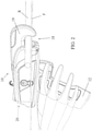
- the figure 2 shows the engagement of the beak 19 of the tie laying head 18 on a branch R and a trellising wire F to be secured by means of a tie.
- the clip is not shown.
- the twister 30 has two prehensile arms. They constitute tie wire trainers 32 intended to grip and drive a tie wire which will be twisted. For simplicity, the tie wire is not shown in the figure.
- a hook 40 In the vicinity of the twister one can note the presence of a hook 40, The hook is sheltered by a front part of the casing forming the beak 19 visible on the figure 1 and 2 .
- the hook 40 is pivotally mounted on a pivot 42. It is shown in an open position allowing the introduction of elements to be attached under the beak of the attachment laying head. In a closed position, shown in the figure 4 , the hook 40 closes the spout.
- a movement transmission mechanism 60 associated with the electric motor, makes it possible to transmit the movement of the motor to the twister 30.
- the movement of the motor is also transmitted to the hook 40, to a feeder 44 for the tie wire, and to a knife 46 intended to cut the tie wire.
- the transmission mechanism 50 is better visible on the figure 4 which takes components of the mechanism in three dimensions in their position in the tool. It comprises a drive pinion 52 of a longitudinal shaft 54 on which is mounted the twister 30. The longitudinal shaft 54 is connected via the drive pinion 52 to an electric motor associated with the rotation of the twister.
- the pinion 52 is connected to the longitudinal shaft 54 by a freewheel mechanism 56 making it possible to drive the shaft longitudinal 54 for a direction of rotation of the motor only. A rotation of the motor in a reverse direction of rotation is free without driving the longitudinal shaft 54.
- the transmission mechanism 50 also comprises a sequential actuation wheel 80 driven by an electric motor associated with the sequential actuation wheel.
- said wheel is also coupled to the motor by a freewheel mechanism 66.
- the freewheel mechanism 66 makes it possible to drive the sequential actuation wheel only for rotation of the motor in a direction opposite to that driving the twister.
- a coupling toothed wheel makes it possible to couple the electric motor 22 to the sequential actuation wheel 60 and to the pinion 52 for driving the twister.
- the coupling wheel is not visible on the figure 4 . She appears on the figure 5 with reference 58.
- the sequential actuating wheel 60 is a toothed wheel making it possible to actuate the tie wire advancement driver 44 by gear.
- the advancement trainer 44 comprises a drive roller 70 associated with a pressure roller 72.
- the drive roller 70 is provided with teeth intended to promote the driving of the tie wire. It is mounted on a shaft 91, integral in rotation with a toothed wheel 74 in permanent engagement with the sequential actuation wheel 60.
- the sequential actuation wheel 60 has on its side a first roller 80 forming a cam.
- the first roller forming a cam 80 actuates a lever 82, loaded by a spring 84 and actuating the knife 46 for cutting the wire by means of a first link 86.
- the knife 46 is formed by a rotating guillotine intercepting the path of the tie wire.
- the guillotine is also provided with an actuating lever 88 with a pivot receiving the first rod 86.
- the first link 86 passes over the shaft 91 carrying the drive roller 70, and carries the pressure roller 72.
- the pressure roller is mounted in free rotation around a shaft 78 integral with the connecting rod 86.
- the figure 5 shows another function of the sequential actuation wheel which is that of actuation of the hook 40. It also shows the actuation of the transmission mechanism 50 by the motor 22 and via a bevel pinion 26 on the motor shaft cooperating with the bevel wheel 58. This corresponds to the preferred embodiment in which a single motor is associated both with the sequential actuation wheel and with the rotation of the twister.
- a second roller 90 forming a cam, is mounted on the sequential actuation wheel 60, on a face opposite to that receiving the first roller forming a cam.
- the second roller forming a cam 90 is provided to cooperate with a second lever 92.
- the movement of the second lever 92 is a rotation around the shaft 91. It is transmitted to a second rod 96 connected to a lever 98 of the hook 40 by the through a pivot 42.
- the second link 96 is loaded by a spring 94.
- the interaction of the second roller 90 with the second lever 92 allows a movement of the hook 40 from its closed position, visible at the figure 4 , towards its open position, visible at the figure 5 .
- the spring 94 returns the second link 96 to a rest position in which the hook is closed.
- the hook 40 is provided with a groove 41, which forms a guide section for the tie wire.
- the path of the tie wire thus passes between drive roller 70 and pressure roller 72, then passes through the guillotine forming knife 46 to engage in the groove 41 of the hook and reach a fixed guide end 100 located in the extension of a free end 43 of the hook 40 at the rear of the twister 30.
- All the organs located on the path of the tie wire, and in particular the mechanical driver 44, the guillotine forming the knife 46, the groove 41 of the hook, the twister 30 and the fixed guide end 100 constitute a guide for a tie wire.
- the tether as such is an accessory of the device and is not part of it. He is not shown.
- the twister 30 and in particular the prehensile arms, forming the trainer 32 of the twister 30, intercept the tie wire upstream of the hook, at the exit of the guillotine 46, and downstream of the free end of the hook, before the fixed guide end 100.
- a good interception of the tie wire is obtained thanks to an appropriate angular positioning of the twister 30 shown in figure 4 .
- This position is reached by controlling the electric motor in which its speed is slaved to the angular position of the twister, in particular when approaching the desired position.
- the angular position of the twister is measured using a sensor 110 which constitutes the "second angular position sensor" within the meaning of the invention.
- the second angular position sensor is associated with two magnets 112 mounted on a support 114 integral in rotation with the twister 30 symmetrically with respect to the longitudinal shaft 54 and in a plane perpendicular to this shaft.
- the second angular sensor 110 is preferably an analog sensor. This is a Hall effect sensor or a magnetoresistance sensitive to variations in a magnetic field produced by each of the two magnets 112.
- the field is maximum when one of the magnets 112 is closest to the sensor, but the sensor begins to deliver a signal as soon as a magnet approaches, or vice versa until its event
- the second angular position signal emitted by the angular sensor 110 passes through two maximums respectively for the two magnets diametrically opposed with respect to the longitudinal shaft 54 during a complete revolution of the shaft.
- the maximum signal gives the precise position of the twister in the rest position.
- the signal continuously passes through a minimum when the two magnets are separated from the angular sensor 110 by more than 20 degrees.
- the sensor 110 is connected to an electronic control circuit 120 of the motor 22 which exploits the variations of the second angular position signal to control the speed of rotation of the motor and to control a stoppage of the twister in a position of alignment with the guide of the tie wire and in particular with a portion of the guide constituted by the hook 40.
- the stopping of the twister is preceded by a deceleration phase during which its speed decreases with the approach of the stop position
- One or several stop positions can be stored in a memory 121 of the electronic control circuit.
- the electronic control circuit 120 of the motor 22 also receives a signal, in this case the first angular position signal, from another sensor 130 which constitutes the “first angular position sensor” within the meaning of the invention. It is schematically visible on the figure 5 .
- the first angular position sensor 130 is preferably a sensor with one and preferably several Hall effect probes. It is for example a sensor of the type marketed by the company MPS under the reference MP9960.
- the first angular position sensor 130 is associated with a magnet 132 mounted on a shaft 134 integral in rotation with the sequential actuation wheel 60.
- the magnet 132 has two North and South magnetic poles both positioned in the same plane perpendicular to the axis of the shaft 134.
- the shaft 134 in question is a shaft which receives the sequential actuation wheel and the coupling toothed wheel 58 in engagement with the drive motor.
- the rotation of the shaft 134 and of the magnet 132 with the sequential actuating wheel 60 creates at the level of the first angular position sensor 130 a variable magnetic field which is converted into an angular position datum of the actuating wheel sequential by the first angular position sensor 130.
- This signal is supplied to the electronic control circuit 120 of the motor 22 to slave the speed of the motor to the angular position of the sequential actuation wheel and to cause motor stop phases when the latter is operated with a direction of rotation driving the sequential actuation wheel 60, including for positions distinct from those of the actuation of the cams 80 and 90.
- the first angular position sensor 130 may comprise a simple sensor, for example a Hall effect sensor associated with an indexing magnet of the sequential actuation wheel, indicating a reference angular position as by example the start position of the fastening cycle.
- the signal of the reference angular position is then combined with a measurement 140 of the characteristics of the phases of the motor such as for example the voltage, giving a relative angular position of the sensor of the rotor of the motor 22, the whole being calculated with the reduction characteristics in a computer 180 of the electronic control circuit 120 to produce the first angular position signal.
- the computer 160 is also part of the first angular position sensor.
- Two particular stopping positions are in particular envisaged. On the one hand, it is a position, represented in figure 5 , in which the hook 40 is at its maximum open position, and on the other hand a position, shown in figure 4 , in which the pinch roller 72 is lifted from the drive roller 70 in a movement participating in the cutting of the link.
- the open position of the hook is an important position in which the elements to be tied can be engaged in the tying head 18.
- the raised position of the roller is a position facilitating the cleaning of the mechanical drive 44 and, if necessary, the replacement of the pressure roller 72. It also makes it possible to engage a tie wire in the advancement drive 44 or to remove a tie wire that has stuck.
- the selection of stop and maintenance positions can be performed by a control interface on the body of the laying device visible for example in the figures 1 to 3 , in particular with a “MODE” button which makes it possible to select particular pre-established actions, leading to commands of the motor via its electronic control circuit and establishing rotation in a predetermined position of the sequential actuation wheel.
- the selection of stop and maintenance positions can also be coupled with a particular actuation of the trigger 14, for example by maintaining the pressure on this trigger for a predetermined duration, for example a duration of 2 seconds, greater than an actuation normal trigger.
- the operation of the device 10 for attaching is further illustrated by the figure 6 which gives in continuous line a speed set point 200 of the motor rotational speed during a fastener installation cycle.
- the instruction 300 of the cycle of the installation of a fastener in the state of the art constituted by the apparatus described in the document EP0783323 .
- the speed of rotation is indicated on the ordinate.
- Positive values indicate a direction of rotation of the electric motor associated with the rotation of the sequential actuation wheel.
- Negative values Indicate an opposite direction of rotation of the electric motor causing the rotation of the twister. This is the preferred embodiment with a single motor. In the case where several motors are used, and in particular a separate motor for actuating the rotary twister, the negative values represent the speed setpoint of the electric motor associated with the twister.
- a first phase 202 the electric motor associated with the sequential actuation wheel is actuated.
- the advancement of the link and the closing of the hook are thus actuated simultaneously.
- the sequential actuation wheel continues to advance the link until it arrives at the fixed guide end.
- the first cam that is to say the first roller 80, then comes into contact with the associated lever 82, to cut the link by actuating the guillotine 46 then disengages from the lever 82 to return the pressure roller 72 to pressure on the link thanks to the return spring 84 before stopping the motor.
- the acceleration and deceleration slopes are low, while giving a motor rotation setpoint up to a speed level V20, for example 9000 revolutions per minute. The mechanics of the device are thus less stressed.
- the first phase 202 corresponds to a first phase 302 of the device of the state of the art.
- a second phase 204 the electric motor associated with the rotation of the twister is activated. This corresponds to a change in the direction of rotation of the motor in the case of the proffered embodiment with a single motor.
- the rotary twister is rotated and the sequential actuation wheel then remains in a fixed angular position.
- the twister realizes the fastener by tightening more or less according to the setting desired by the user.
- the acceleration of the motor at the start of this phase makes it possible to reach a level of rotation speed V22, its absolute value being for example 10,000 revolutions per minute.
- the second phase corresponding to the actuation of the twister, comprises a phase 206 of progressive and slow deceleration of the motor.
- the start of the slowing down phase 206 is calculated by the microprocessor as a function of the number of turns to be made to take into account the last turns made at a progressively lower speed until it stops in a position in which the twister is aligned with the tie wire guide. The gradual reduction in speed then makes it possible to precisely position the tie wire twister in its predetermined position directly when the engine is stopped.
- the second phase 204 of the device for laying fasteners of the invention can be compared to a second phase 304 of actuation of the twister of the device of the state of the art.
- the maximum speed of rotation V22 of the motor during the second phase 204 of the apparatus of the invention is higher than the speed V12 of the motor of the apparatus of the prior art.
- the duration of the second phase 204, including the slowing down phase 206 is shorter than the second phase 304 of the apparatus of the state of the art.
- the electric motor associated with the sequential actuation wheel is activated one last time. This corresponds to the change in direction of rotation of the single motor in the preferred embodiment.
- the sequential actuation wheel completes its rotation over one full revolution.
- the twister is stopped and the hook 40 is returned to its initial open position thanks to the second roller 90 acting on the lever 92 while actuating the tie wire trainer to make it cross the twister and advance it partially into the hook.
- the hook is fully raised and the motor stopped, ready for a new tying cycle.
- an additional phase 310 can be noted, preceding a stop phase 308 for the tying gun of the state of the art.
- the additional phase 310 corresponds to a re-indexing of the twister taking into account the rapid deceleration of the motor between its speed V12 at the time of the formation of the twist and its stopping in phase 304.
- This is due to the fact that the effect sensor Hall's prior art apparatus gives a simple angular position pulse of the twister shaft just as the twister reaches that position.
- the complementary phase 310 thus makes it possible to control the rotation of the twister with a speed V14 lower than the speed V12 at the time of the formation of the twist.
- the stop occurs as soon as the next magnet is detected.
- the rotational energy is thus much lower and it is easier to precisely position the twister as soon as the motor stops.
- the motor of the tying gun of the state of the art being as already indicated a direct current motor, its speeds of rotation are lower than a three-phase synchronous motor with permanent magnets and it is more difficult to control low acceleration and deceleration slopes as shown by phases 302, 304, 308 and 310 of an attachment cycle of this device.
- the speed levels V10, V12 and V14 are for example and respectively 7400, 6000 and 3500 revolutions per minute.
- the total duration T1 of the cycle is of the order of 500 ms, but in the case of a DC motor it can vary according to values of 450 ms when the battery is charged at 550ms when discharged while still allowing a tie cycle to be completed. It is greater than the total cycle time T2 obtained with the device for fitting fasteners of the invention, which is of the order of 400 ms.
- the use of both a three-phase synchronous motor with permanent magnets having a faster rotation speed capacity, of a servo-control of its speed and the use of two sensors giving continuous angular positions of the main organs allows , to anticipate their position, to accelerate the average speed of the cycle while controlling the acceleration and deceleration phases of the motor. The operation is certainly faster but also more respectful of the mechanics, improving its lifespan and reliability. It may also be noted that the digital control of the motor is not very sensitive to the state of charge of the battery. Thus the values of T1 are almost identical regardless of this exchange rate.
Landscapes
- Life Sciences & Earth Sciences (AREA)
- Botany (AREA)
- Environmental Sciences (AREA)
- Basic Packing Technique (AREA)
- Harvester Elements (AREA)
Claims (15)
- Gerät (10) zum Anbringen von Befestigungen, umfassend:- eine Drahtführung (41, 44, 46, 100) für einen Befestigungsdraht, die sich zwischen einer Drahtaufnahme (20) und einem festen Führungsende (100) erstreckt,- einen schwenkbaren Haken (40), der ein freies Hakenende (43) aufweist, wobei der Haken einen Abschnitt der Drahtführung (41) bildet und einen Schwenk-Freiheitsgrad zwischen einer offenen Position, in der das freie Hakenende (43) von dem festen Führungsende (100) weggeschoben ist, und einer geschlossenen Position, in der das freie Hakenende (43) mit dem festen Führungsende (100) ausgerichtet ist, aufweist,- einen mechanischen Befestigungsdrahtmitnehmer (44), der oberhalb des Hakens (40) angeordnet ist,- ein Messer (46) zum Trennen des Drahts, wobei das Messer oberhalb des Hakens angeordnet ist,- eine sich drehende Verdrillvorrichtung (30) mit Befestigungsdrahtmitnehmern (32), die oberhalb und unterhalb des Hakens angeordnet sind, und wobei die Mitnehmer unterhalb des Messers zum Aufnehmen eines Befestigungsdrahts in eine Ausrichtungsposition der sich drehenden Verdrillvorrichtung mit der Drahtführung konfiguriert sind,- einen Elektromotor (22), der mit einem Übertragungsmechanismus (50) verbunden ist und ein Rad zur sequenziellen Betätigung (60) für den Haken (40) und das Messer (46) umfasst, dadurch gekennzeichnet, dass das Gerät ferner Folgendes umfasst:- einen ersten Winkelpositionssensor (130) des Rads zur sequenziellen Betätigung (60), der zum Liefern eines stufenlosen ersten Winkelpositionssignals über einen Drehwinkelbereich des Rads zur sequenziellen Betätigung (60) von 360 Grad konfiguriert ist, wobei der erste Winkelpositionssensor dem Rad zur sequenziellen Betätigung (60) und/oder dem Elektromotor (22) zugeordnet ist,- einen elektronischen Steuerkreis (120) des Elektromotors (22), der mit dem ersten Winkelpositionssensor (130) verbunden ist und das erste Winkelpositionssignal des ersten Winkelpositionssensors zur Steuerung des Motors in Abhängigkeit von dem ersten Winkelpositionssignal empfängt.
- Gerät nach Anspruch 1, wobei der erste Winkelpositionssensor (130) ein Hall-Sensor ist, der mindestens einem Drehmagneten (132), der am Ende einer Welle montiert ist, einer mit mindestens einem aus dem Rad zur sequenziellen Betätigung (60) und dem Elektromotor (22) drehfest verbundenen Welle (134), zugeordnet ist.
- Gerät nach Anspruch 1, wobei der Elektromotor (22) ein bürstenloser, dreiphasiger Permanentmagnet-Synchronmotor ist und wobei der erste Winkelpositionssensor eine Messschaltung (140) für mindestens eines aus einer Spannung und einem Strom der Phasen des Motors, und eine Recheneinheit (160) umfasst, die zum Festlegen des ersten Winkelpositionssignals in Abhängigkeit von einem Messsignal der Messschaltung konfiguriert ist.
- Gerät nach einem der Ansprüche 1 bis 3, wobei der elektrische Steuerkreis (120) des Elektromotors (22) einen Speicher (121) zur Speicherung der vorbestimmten Positionen des Rads zur sequenziellen Betätigung, die mit Steuerphasen des Motors verbunden sind, enthält.
- Gerät nach einem der vorhergehenden Ansprüche, ferner umfassend einen zweiten Winkelpositionssensor (110) der sich drehenden Verdrillvorrichtung (30), einen Elektromotor, der der sich drehenden Verdrillvorrichtung zugeordnet ist, und einen elektronischen Steuerkreis des Elektromotors, der der sich drehenden Verdrillvorrichtung zugeordnet ist, wobei der elektronische Steuerkreis des der sich drehenden Verdrillvorrichtung zugeordneten Elektromotors mit dem zweiten Winkelpositionssensor verbunden ist und ein zweites Winkelpositionssignal des zweiten Winkelpositionssensors zur Steuerung des Motors in Abhängigkeit von dem zweiten Winkelpositionssignal empfängt.
- Gerät nach Anspruch 5, wobei der der sich drehenden Verdrillvorrichtung zugeordnete Elektromotor der Elektromotor (22) ist, der mit dem Übertragungsmechanismus (50) verbunden ist und das Rad zur sequenziellen Betätigung (60) umfasst, und wobei der elektronische Steuerkreis (120) des der sich drehenden Verdrillvorrichtung zugeordneten Elektromotors der elektronische Steuerkreis (120) ist, der mit dem ersten Winkelpositionssensor verbunden ist.
- Gerät nach Anspruch 5, wobei der der sich drehenden Verdrillvorrichtung zugeordnete Elektromotor ein von dem mit dem Übertragungsmechanismus (50) verbundenen Elektromotor, der das Rad zur sequenziellen Betätigung (60) umfasst, separater Elektromotor ist.
- Gerät nach Anspruch 5, wobei der zweite Winkelpositionssensor (110) ein Hall-Sensor mit stufenlos veränderlichem Signal ist, der auf eine Drehung einer mit der Verdrillvorrichtung (30) drehfest verbundenen Welle (134) reagiert.
- Gerät nach Anspruch 5, wobei der zweite Winkelpositionssensor (110) mit zwei Magneten (112) verbunden ist, die symmetrisch an einer Halterung (114) auf einer Ebene senkrecht zur mit der Verdrillvorrichtung drehfest verbundenen Welle (54), montiert sind.
- Gerät nach einem der vorhergehenden Ansprüche, wobei der elektronische Steuerkreis (120) des mit dem Übertragungsmechanismus (50) verbundenen Elektromotors (22) jeweils der elektronische Steuerkreis des der Verdrillvorrichtung zugeordneten Elektromotors für mindestens eine erste Stillstandphase (208) der Drehung des mit dem Übertragungsmechanismus (50) verbundenen Elektromotors jeweils des der Verdrillvorrichtung zugeordneten Elektromotors konfiguriert ist, in deren Verlauf die Drehgeschwindigkeit einer Winkelposition des Rads zur sequenziellen Betätigung unterworfen ist.
- Gerät nach Anspruch 10, wobei die erste Stillstandphase (208) der geschlossenen Position des Hakens zugeordnet ist.
- Gerät nach Anspruch 10, wobei der Mitnehmer (44) zum Vorschieben des Befestigungsdrahts eine Antriebsrolle (70) und eine Druckrolle (72) umfasst, wobei die Druckrolle zwischen einer angenäherten Position der Antriebsrolle und einer erhöhten Position, die einen Durchgang zwischen der Druckrolle und der Antriebsrolle freilegt, verschiebbar ist, und wobei eine Stillstandphase des Motors (22) der erhöhten Position der Druckrolle zugeordnet ist.
- Gerät nach einem der vorhergehenden Ansprüche, wobei der elektronische Steuerkreis (120) des mit dem Übertragungsmechanismus (50) verbundenen Elektromotors (22) jeweils der elektronische Steuerkreis des der Verdrillvorrichtung zugeordneten Elektromotors ferner für mindestens eine zweite Stillstandphase (206) der Drehung des mit dem Übertragungsmechanismus (50) verbundenen Elektromotors jeweils des der Verdrillvorrichtung zugeordneten Elektromotors konfiguriert ist, in deren Verlauf die Drehgeschwindigkeit einer Winkelposition der Verdrillvorrichtung (30) unterworfen ist, wobei die zweite Stillstandphase der Ausrichtungsposition der Verdrillvorrichtung mit der Drahtführung zugeordnet ist.
- Gerät nach Anspruch 1, wobei der Übertragungsmechanismus (50) eine Freilaufkupplung (56, 66) enthält, die wahlweise mit dem Rad zur sequenziellen Betätigung (60) und mit der Verdrillvorrichtung (30) für entgegengesetzte Drehrichtungen des Elektromotors (22) in Eingriff gelangt.
- Gerät nach Anspruch 12, wobei das Rad zur sequenziellen Betätigung (60) ein Zahnrad ist, das durch eine Verzahnung (60, 74) mit der Antriebsrolle (70) verbunden ist.
Applications Claiming Priority (2)
| Application Number | Priority Date | Filing Date | Title |
|---|---|---|---|
| FR1870309A FR3079104B1 (fr) | 2018-03-20 | 2018-03-20 | Appareil pour la pose d'attaches filaires |
| PCT/FR2019/050475 WO2019180339A1 (fr) | 2018-03-20 | 2019-03-04 | Appareil pour la pose d'attaches filaires |
Publications (2)
| Publication Number | Publication Date |
|---|---|
| EP3768069A1 EP3768069A1 (de) | 2021-01-27 |
| EP3768069B1 true EP3768069B1 (de) | 2022-02-23 |
Family
ID=62751197
Family Applications (1)
| Application Number | Title | Priority Date | Filing Date |
|---|---|---|---|
| EP19715541.9A Active EP3768069B1 (de) | 2018-03-20 | 2019-03-04 | Vorrichtung zum anbringen von drahtbefestigungselementen |
Country Status (8)
| Country | Link |
|---|---|
| US (1) | US20210037720A1 (de) |
| EP (1) | EP3768069B1 (de) |
| JP (1) | JP2021517542A (de) |
| CN (1) | CN111867364B (de) |
| AU (1) | AU2019239898A1 (de) |
| ES (1) | ES2912464T3 (de) |
| FR (1) | FR3079104B1 (de) |
| WO (1) | WO2019180339A1 (de) |
Families Citing this family (2)
| Publication number | Priority date | Publication date | Assignee | Title |
|---|---|---|---|---|
| CN113170679A (zh) * | 2021-05-29 | 2021-07-27 | 东莞市嘉航实业有限公司 | 一种三电机驱动的捆绑机构及其绑枝机 |
| DE202023100955U1 (de) * | 2023-02-28 | 2024-05-29 | Hellermanntyton Gmbh | Verbessertes Bündelwerkzeug zum abfallfreien Bündeln eines Bindeguts |
Family Cites Families (16)
| Publication number | Priority date | Publication date | Assignee | Title |
|---|---|---|---|---|
| US3368590A (en) * | 1965-06-28 | 1968-02-13 | David P. Welden | Wire-tying machine |
| JPS61191764A (ja) * | 1985-02-18 | 1986-08-26 | 湯口 貞雄 | 鉄筋の結束装置 |
| US4912912A (en) * | 1987-05-30 | 1990-04-03 | Strapack Corporation | Control apparatus in strapping machine |
| JPH07275982A (ja) * | 1994-04-08 | 1995-10-24 | Toyota Kihan:Kk | 鉄筋結束機 |
| FR2738456B1 (fr) * | 1995-09-12 | 1997-10-24 | Pellenc Sa | Appareil pour la pose d'attaches, par exemple pour l'attachage de la vigne |
| FR2814717B1 (fr) * | 2000-10-04 | 2003-02-28 | Papeteries Matussiere Forest | Appareil pour la pose automatique de liens torsades |
| JP4211059B2 (ja) * | 2004-01-09 | 2009-01-21 | マックス株式会社 | 鉄筋結束機、ワイヤリール及びワイヤリールの識別方法 |
| JP4548584B2 (ja) * | 2004-07-16 | 2010-09-22 | マックス株式会社 | 鉄筋結束機 |
| US20070034338A1 (en) * | 2005-08-09 | 2007-02-15 | Hisashi Ogawa | Binding apparatus for binding both ends of an adhesive tape around an object |
| JP4961808B2 (ja) * | 2006-04-05 | 2012-06-27 | マックス株式会社 | 鉄筋結束機 |
| JP5532610B2 (ja) * | 2008-05-19 | 2014-06-25 | マックス株式会社 | ワイヤリール及び鉄筋結束機 |
| CN101353088B (zh) * | 2008-06-20 | 2010-07-28 | 蔡昌开 | 钢筋捆扎机 |
| CN201232363Y (zh) * | 2008-07-17 | 2009-05-06 | 易笑婕 | 一种电动钢筋捆扎机 |
| JP2012101860A (ja) * | 2012-01-30 | 2012-05-31 | Max Co Ltd | 鉄筋結束機 |
| CN106818391A (zh) * | 2017-02-21 | 2017-06-13 | 方培锵 | 一种绑枝机 |
| CN107642239B (zh) * | 2017-09-29 | 2019-06-25 | 湖北工业大学 | 一种便携式钢筋自动扎丝机 |
-
2018
- 2018-03-20 FR FR1870309A patent/FR3079104B1/fr not_active Expired - Fee Related
-
2019
- 2019-03-04 CN CN201980020322.3A patent/CN111867364B/zh active Active
- 2019-03-04 JP JP2020548781A patent/JP2021517542A/ja active Pending
- 2019-03-04 EP EP19715541.9A patent/EP3768069B1/de active Active
- 2019-03-04 ES ES19715541T patent/ES2912464T3/es active Active
- 2019-03-04 WO PCT/FR2019/050475 patent/WO2019180339A1/fr not_active Ceased
- 2019-03-04 AU AU2019239898A patent/AU2019239898A1/en not_active Abandoned
- 2019-03-04 US US16/964,054 patent/US20210037720A1/en not_active Abandoned
Also Published As
| Publication number | Publication date |
|---|---|
| CN111867364A (zh) | 2020-10-30 |
| FR3079104B1 (fr) | 2020-05-29 |
| JP2021517542A (ja) | 2021-07-26 |
| FR3079104A1 (fr) | 2019-09-27 |
| EP3768069A1 (de) | 2021-01-27 |
| CN111867364B (zh) | 2022-07-08 |
| WO2019180339A1 (fr) | 2019-09-26 |
| ES2912464T3 (es) | 2022-05-26 |
| AU2019239898A1 (en) | 2020-09-24 |
| US20210037720A1 (en) | 2021-02-11 |
Similar Documents
| Publication | Publication Date | Title |
|---|---|---|
| EP0021935B1 (de) | Geschwindigkeitsregelanlage für Fahrzeuge | |
| EP0115995A1 (de) | Verfahren und Vorrichtung zur Steuerung der Bewegung eines Maschinenteils und ihr Gebrauch in einer Rundballenpresse | |
| FR2480011A1 (fr) | Dispositif destine a faire tourner les tambours d'une machine a sous, cette machine, appareil de jeu et mecanisme de commande d'un arbre pour cet appareil | |
| EP1322148B1 (de) | Vorrichtung für die selbsttätige anlage von verdrillten bändern | |
| EP1574125B1 (de) | Elektronisch geregeltes Schneidwerkzeug | |
| CH657641A5 (fr) | Dispositif d'entrainement en rotation d'au moins un predelivreur-mesureur de trame, sur une machine a tisser sans navette. | |
| FR2557601A1 (fr) | Regulateur de tension d'un ruban elastique et similaire, notamment pour machine a coudre destinee a attacher des rubans sur un tissu | |
| EP3768069A1 (de) | Vorrichtung zum anbringen von drahtbefestigungselementen | |
| EP0265471B1 (de) | Schneidvorrichtung für ein kontinuierlich hergestelltes rohr | |
| FR2595675A1 (fr) | Procede et appareil pour distribuer et enrouler du papier d'empaquetage | |
| CH371373A (fr) | Machine pour enrouler un élément filiforme sur une bobine | |
| EP2054200B1 (de) | Werkzeug mit hilfsvorrichtung zur betätigung | |
| FR2524502A1 (fr) | Metier a retordre, en particulier pour le retordage de fils de verre | |
| FR2461676A1 (fr) | Procede pour la commande automatique de la trajectoire du fardeau d'un engin de levage et dispositif pour sa mise en oeuvre | |
| EP0204628A2 (de) | Verfahren und Nähmaschine um eine Naht automatisch in einem bestimmten Abstand vom Rand eines Werkstückes fertig zu machen | |
| EP2615505A1 (de) | Anzeigemechanismus nach Informationsanfrage für Uhrwerk | |
| EP0078745B1 (de) | Elektrische Steuervorrichtung für eine rotierende Schere | |
| EP2826363B1 (de) | Tragbare Bindevorrichtung und Verfahren zur Verwendung in der Landwirtschaft | |
| JP2015189475A (ja) | テープ結束機 | |
| JP6511264B2 (ja) | テープ結束機 | |
| FR2596428A1 (fr) | Procede et machine a coudre pour realiser automatiquement une fin de couture a une distance determinee du bord d'une etoffe | |
| EP1271739A1 (de) | Kalibrierung des Verhältnisses zwischen Strom und Einklemmkraft eines elektrischen Fensterhebers mit federgespannten Kabeln | |
| FR2582682A1 (fr) | Procede pour rendre automatique l'execution d'une fin de couture a une distance determinee du bord de l'etoffe et machine a coudre mise en oeuvre | |
| FR2495998A1 (fr) | Dispositif d'une machine enrouleuse de bande en tube pour commander un equipement de coupe | |
| EP1816534A1 (de) | Verfahren zur Programmierung eines elektrischen Stellgliedes und elektriches Stellglied zur Durchführung dieses Verfahrens |
Legal Events
| Date | Code | Title | Description |
|---|---|---|---|
| STAA | Information on the status of an ep patent application or granted ep patent |
Free format text: STATUS: UNKNOWN |
|
| STAA | Information on the status of an ep patent application or granted ep patent |
Free format text: STATUS: THE INTERNATIONAL PUBLICATION HAS BEEN MADE |
|
| PUAI | Public reference made under article 153(3) epc to a published international application that has entered the european phase |
Free format text: ORIGINAL CODE: 0009012 |
|
| STAA | Information on the status of an ep patent application or granted ep patent |
Free format text: STATUS: REQUEST FOR EXAMINATION WAS MADE |
|
| 17P | Request for examination filed |
Effective date: 20200825 |
|
| AK | Designated contracting states |
Kind code of ref document: A1 Designated state(s): AL AT BE BG CH CY CZ DE DK EE ES FI FR GB GR HR HU IE IS IT LI LT LU LV MC MK MT NL NO PL PT RO RS SE SI SK SM TR |
|
| AX | Request for extension of the european patent |
Extension state: BA ME |
|
| RIN1 | Information on inventor provided before grant (corrected) |
Inventor name: LOPEZ, BERNARD Inventor name: CHAUDET, NICOLAS Inventor name: GILBERT, PHILIPPE |
|
| DAV | Request for validation of the european patent (deleted) | ||
| DAX | Request for extension of the european patent (deleted) | ||
| GRAP | Despatch of communication of intention to grant a patent |
Free format text: ORIGINAL CODE: EPIDOSNIGR1 |
|
| STAA | Information on the status of an ep patent application or granted ep patent |
Free format text: STATUS: GRANT OF PATENT IS INTENDED |
|
| INTG | Intention to grant announced |
Effective date: 20211118 |
|
| GRAS | Grant fee paid |
Free format text: ORIGINAL CODE: EPIDOSNIGR3 |
|
| GRAA | (expected) grant |
Free format text: ORIGINAL CODE: 0009210 |
|
| STAA | Information on the status of an ep patent application or granted ep patent |
Free format text: STATUS: THE PATENT HAS BEEN GRANTED |
|
| AK | Designated contracting states |
Kind code of ref document: B1 Designated state(s): AL AT BE BG CH CY CZ DE DK EE ES FI FR GB GR HR HU IE IS IT LI LT LU LV MC MK MT NL NO PL PT RO RS SE SI SK SM TR |
|
| REG | Reference to a national code |
Ref country code: GB Ref legal event code: FG4D Free format text: NOT ENGLISH |
|
| REG | Reference to a national code |
Ref country code: CH Ref legal event code: EP |
|
| REG | Reference to a national code |
Ref country code: AT Ref legal event code: REF Ref document number: 1469747 Country of ref document: AT Kind code of ref document: T Effective date: 20220315 |
|
| REG | Reference to a national code |
Ref country code: IE Ref legal event code: FG4D Free format text: LANGUAGE OF EP DOCUMENT: FRENCH |
|
| REG | Reference to a national code |
Ref country code: DE Ref legal event code: R096 Ref document number: 602019011892 Country of ref document: DE |
|
| REG | Reference to a national code |
Ref country code: ES Ref legal event code: FG2A Ref document number: 2912464 Country of ref document: ES Kind code of ref document: T3 Effective date: 20220526 |
|
| REG | Reference to a national code |
Ref country code: LT Ref legal event code: MG9D |
|
| REG | Reference to a national code |
Ref country code: NL Ref legal event code: MP Effective date: 20220223 |
|
| REG | Reference to a national code |
Ref country code: AT Ref legal event code: MK05 Ref document number: 1469747 Country of ref document: AT Kind code of ref document: T Effective date: 20220223 |
|
| PG25 | Lapsed in a contracting state [announced via postgrant information from national office to epo] |
Ref country code: SE Free format text: LAPSE BECAUSE OF FAILURE TO SUBMIT A TRANSLATION OF THE DESCRIPTION OR TO PAY THE FEE WITHIN THE PRESCRIBED TIME-LIMIT Effective date: 20220223 Ref country code: RS Free format text: LAPSE BECAUSE OF FAILURE TO SUBMIT A TRANSLATION OF THE DESCRIPTION OR TO PAY THE FEE WITHIN THE PRESCRIBED TIME-LIMIT Effective date: 20220223 Ref country code: PT Free format text: LAPSE BECAUSE OF FAILURE TO SUBMIT A TRANSLATION OF THE DESCRIPTION OR TO PAY THE FEE WITHIN THE PRESCRIBED TIME-LIMIT Effective date: 20220623 Ref country code: NO Free format text: LAPSE BECAUSE OF FAILURE TO SUBMIT A TRANSLATION OF THE DESCRIPTION OR TO PAY THE FEE WITHIN THE PRESCRIBED TIME-LIMIT Effective date: 20220523 Ref country code: NL Free format text: LAPSE BECAUSE OF FAILURE TO SUBMIT A TRANSLATION OF THE DESCRIPTION OR TO PAY THE FEE WITHIN THE PRESCRIBED TIME-LIMIT Effective date: 20220223 Ref country code: LT Free format text: LAPSE BECAUSE OF FAILURE TO SUBMIT A TRANSLATION OF THE DESCRIPTION OR TO PAY THE FEE WITHIN THE PRESCRIBED TIME-LIMIT Effective date: 20220223 Ref country code: HR Free format text: LAPSE BECAUSE OF FAILURE TO SUBMIT A TRANSLATION OF THE DESCRIPTION OR TO PAY THE FEE WITHIN THE PRESCRIBED TIME-LIMIT Effective date: 20220223 Ref country code: BG Free format text: LAPSE BECAUSE OF FAILURE TO SUBMIT A TRANSLATION OF THE DESCRIPTION OR TO PAY THE FEE WITHIN THE PRESCRIBED TIME-LIMIT Effective date: 20220523 |
|
| PG25 | Lapsed in a contracting state [announced via postgrant information from national office to epo] |
Ref country code: PL Free format text: LAPSE BECAUSE OF FAILURE TO SUBMIT A TRANSLATION OF THE DESCRIPTION OR TO PAY THE FEE WITHIN THE PRESCRIBED TIME-LIMIT Effective date: 20220223 Ref country code: LV Free format text: LAPSE BECAUSE OF FAILURE TO SUBMIT A TRANSLATION OF THE DESCRIPTION OR TO PAY THE FEE WITHIN THE PRESCRIBED TIME-LIMIT Effective date: 20220223 Ref country code: GR Free format text: LAPSE BECAUSE OF FAILURE TO SUBMIT A TRANSLATION OF THE DESCRIPTION OR TO PAY THE FEE WITHIN THE PRESCRIBED TIME-LIMIT Effective date: 20220524 Ref country code: FI Free format text: LAPSE BECAUSE OF FAILURE TO SUBMIT A TRANSLATION OF THE DESCRIPTION OR TO PAY THE FEE WITHIN THE PRESCRIBED TIME-LIMIT Effective date: 20220223 Ref country code: AT Free format text: LAPSE BECAUSE OF FAILURE TO SUBMIT A TRANSLATION OF THE DESCRIPTION OR TO PAY THE FEE WITHIN THE PRESCRIBED TIME-LIMIT Effective date: 20220223 |
|
| PG25 | Lapsed in a contracting state [announced via postgrant information from national office to epo] |
Ref country code: IS Free format text: LAPSE BECAUSE OF FAILURE TO SUBMIT A TRANSLATION OF THE DESCRIPTION OR TO PAY THE FEE WITHIN THE PRESCRIBED TIME-LIMIT Effective date: 20220623 |
|
| PG25 | Lapsed in a contracting state [announced via postgrant information from national office to epo] |
Ref country code: SM Free format text: LAPSE BECAUSE OF FAILURE TO SUBMIT A TRANSLATION OF THE DESCRIPTION OR TO PAY THE FEE WITHIN THE PRESCRIBED TIME-LIMIT Effective date: 20220223 Ref country code: SK Free format text: LAPSE BECAUSE OF FAILURE TO SUBMIT A TRANSLATION OF THE DESCRIPTION OR TO PAY THE FEE WITHIN THE PRESCRIBED TIME-LIMIT Effective date: 20220223 Ref country code: RO Free format text: LAPSE BECAUSE OF FAILURE TO SUBMIT A TRANSLATION OF THE DESCRIPTION OR TO PAY THE FEE WITHIN THE PRESCRIBED TIME-LIMIT Effective date: 20220223 Ref country code: EE Free format text: LAPSE BECAUSE OF FAILURE TO SUBMIT A TRANSLATION OF THE DESCRIPTION OR TO PAY THE FEE WITHIN THE PRESCRIBED TIME-LIMIT Effective date: 20220223 Ref country code: DK Free format text: LAPSE BECAUSE OF FAILURE TO SUBMIT A TRANSLATION OF THE DESCRIPTION OR TO PAY THE FEE WITHIN THE PRESCRIBED TIME-LIMIT Effective date: 20220223 Ref country code: CZ Free format text: LAPSE BECAUSE OF FAILURE TO SUBMIT A TRANSLATION OF THE DESCRIPTION OR TO PAY THE FEE WITHIN THE PRESCRIBED TIME-LIMIT Effective date: 20220223 |
|
| REG | Reference to a national code |
Ref country code: DE Ref legal event code: R097 Ref document number: 602019011892 Country of ref document: DE |
|
| PG25 | Lapsed in a contracting state [announced via postgrant information from national office to epo] |
Ref country code: MC Free format text: LAPSE BECAUSE OF FAILURE TO SUBMIT A TRANSLATION OF THE DESCRIPTION OR TO PAY THE FEE WITHIN THE PRESCRIBED TIME-LIMIT Effective date: 20220223 Ref country code: AL Free format text: LAPSE BECAUSE OF FAILURE TO SUBMIT A TRANSLATION OF THE DESCRIPTION OR TO PAY THE FEE WITHIN THE PRESCRIBED TIME-LIMIT Effective date: 20220223 |
|
| REG | Reference to a national code |
Ref country code: BE Ref legal event code: MM Effective date: 20220331 |
|
| PLBE | No opposition filed within time limit |
Free format text: ORIGINAL CODE: 0009261 |
|
| STAA | Information on the status of an ep patent application or granted ep patent |
Free format text: STATUS: NO OPPOSITION FILED WITHIN TIME LIMIT |
|
| PG25 | Lapsed in a contracting state [announced via postgrant information from national office to epo] |
Ref country code: LU Free format text: LAPSE BECAUSE OF NON-PAYMENT OF DUE FEES Effective date: 20220304 Ref country code: IE Free format text: LAPSE BECAUSE OF NON-PAYMENT OF DUE FEES Effective date: 20220304 |
|
| 26N | No opposition filed |
Effective date: 20221124 |
|
| PG25 | Lapsed in a contracting state [announced via postgrant information from national office to epo] |
Ref country code: SI Free format text: LAPSE BECAUSE OF FAILURE TO SUBMIT A TRANSLATION OF THE DESCRIPTION OR TO PAY THE FEE WITHIN THE PRESCRIBED TIME-LIMIT Effective date: 20220223 Ref country code: BE Free format text: LAPSE BECAUSE OF NON-PAYMENT OF DUE FEES Effective date: 20220331 |
|
| GBPC | Gb: european patent ceased through non-payment of renewal fee |
Effective date: 20230304 |
|
| PG25 | Lapsed in a contracting state [announced via postgrant information from national office to epo] |
Ref country code: GB Free format text: LAPSE BECAUSE OF NON-PAYMENT OF DUE FEES Effective date: 20230304 |
|
| PG25 | Lapsed in a contracting state [announced via postgrant information from national office to epo] |
Ref country code: GB Free format text: LAPSE BECAUSE OF NON-PAYMENT OF DUE FEES Effective date: 20230304 |
|
| PG25 | Lapsed in a contracting state [announced via postgrant information from national office to epo] |
Ref country code: MK Free format text: LAPSE BECAUSE OF FAILURE TO SUBMIT A TRANSLATION OF THE DESCRIPTION OR TO PAY THE FEE WITHIN THE PRESCRIBED TIME-LIMIT Effective date: 20220223 Ref country code: CY Free format text: LAPSE BECAUSE OF FAILURE TO SUBMIT A TRANSLATION OF THE DESCRIPTION OR TO PAY THE FEE WITHIN THE PRESCRIBED TIME-LIMIT Effective date: 20220223 |
|
| PG25 | Lapsed in a contracting state [announced via postgrant information from national office to epo] |
Ref country code: HU Free format text: LAPSE BECAUSE OF FAILURE TO SUBMIT A TRANSLATION OF THE DESCRIPTION OR TO PAY THE FEE WITHIN THE PRESCRIBED TIME-LIMIT; INVALID AB INITIO Effective date: 20190304 |
|
| PG25 | Lapsed in a contracting state [announced via postgrant information from national office to epo] |
Ref country code: MT Free format text: LAPSE BECAUSE OF FAILURE TO SUBMIT A TRANSLATION OF THE DESCRIPTION OR TO PAY THE FEE WITHIN THE PRESCRIBED TIME-LIMIT Effective date: 20220223 |
|
| PGFP | Annual fee paid to national office [announced via postgrant information from national office to epo] |
Ref country code: ES Payment date: 20250401 Year of fee payment: 7 |
|
| PGFP | Annual fee paid to national office [announced via postgrant information from national office to epo] |
Ref country code: CH Payment date: 20250401 Year of fee payment: 7 |
|
| PG25 | Lapsed in a contracting state [announced via postgrant information from national office to epo] |
Ref country code: TR Free format text: LAPSE BECAUSE OF FAILURE TO SUBMIT A TRANSLATION OF THE DESCRIPTION OR TO PAY THE FEE WITHIN THE PRESCRIBED TIME-LIMIT Effective date: 20220223 |
|
| PGFP | Annual fee paid to national office [announced via postgrant information from national office to epo] |
Ref country code: DE Payment date: 20260327 Year of fee payment: 8 |
|
| PGFP | Annual fee paid to national office [announced via postgrant information from national office to epo] |
Ref country code: IT Payment date: 20260319 Year of fee payment: 8 |
|
| PGFP | Annual fee paid to national office [announced via postgrant information from national office to epo] |
Ref country code: FR Payment date: 20260205 Year of fee payment: 8 |