EP1574125B1 - Elektronisch geregeltes Schneidwerkzeug - Google Patents
Elektronisch geregeltes Schneidwerkzeug Download PDFInfo
- Publication number
- EP1574125B1 EP1574125B1 EP05352004A EP05352004A EP1574125B1 EP 1574125 B1 EP1574125 B1 EP 1574125B1 EP 05352004 A EP05352004 A EP 05352004A EP 05352004 A EP05352004 A EP 05352004A EP 1574125 B1 EP1574125 B1 EP 1574125B1
- Authority
- EP
- European Patent Office
- Prior art keywords
- follower
- control circuit
- motor
- magnet
- electric motor
- Prior art date
- Legal status (The legal status is an assumption and is not a legal conclusion. Google has not performed a legal analysis and makes no representation as to the accuracy of the status listed.)
- Expired - Lifetime
Links
- 230000005355 Hall effect Effects 0.000 claims abstract description 24
- 230000033001 locomotion Effects 0.000 claims description 19
- 238000005259 measurement Methods 0.000 claims description 11
- 230000002452 interceptive effect Effects 0.000 claims description 3
- 238000000926 separation method Methods 0.000 claims 1
- 238000006073 displacement reaction Methods 0.000 abstract description 3
- 230000009471 action Effects 0.000 description 3
- 238000010276 construction Methods 0.000 description 3
- 230000006870 function Effects 0.000 description 3
- 238000006243 chemical reaction Methods 0.000 description 2
- 238000010586 diagram Methods 0.000 description 2
- 239000006185 dispersion Substances 0.000 description 2
- 230000000750 progressive effect Effects 0.000 description 2
- 238000013138 pruning Methods 0.000 description 2
- 230000004044 response Effects 0.000 description 2
- 230000006978 adaptation Effects 0.000 description 1
- 238000009362 arboriculture Methods 0.000 description 1
- 230000005540 biological transmission Effects 0.000 description 1
- 230000000903 blocking effect Effects 0.000 description 1
- 230000006378 damage Effects 0.000 description 1
- 230000007547 defect Effects 0.000 description 1
- 238000003306 harvesting Methods 0.000 description 1
- 238000003898 horticulture Methods 0.000 description 1
- 239000000463 material Substances 0.000 description 1
- 239000002184 metal Substances 0.000 description 1
- 239000000523 sample Substances 0.000 description 1
- 230000009466 transformation Effects 0.000 description 1
- 238000009369 viticulture Methods 0.000 description 1
- 239000002023 wood Substances 0.000 description 1
Images

Classifications
-
- B—PERFORMING OPERATIONS; TRANSPORTING
- B26—HAND CUTTING TOOLS; CUTTING; SEVERING
- B26B—HAND-HELD CUTTING TOOLS NOT OTHERWISE PROVIDED FOR
- B26B15/00—Hand-held shears with motor-driven blades
-
- A—HUMAN NECESSITIES
- A01—AGRICULTURE; FORESTRY; ANIMAL HUSBANDRY; HUNTING; TRAPPING; FISHING
- A01G—HORTICULTURE; CULTIVATION OF VEGETABLES, FLOWERS, RICE, FRUIT, VINES, HOPS OR SEAWEED; FORESTRY; WATERING
- A01G3/00—Cutting implements specially adapted for horticultural purposes; Delimbing standing trees
- A01G3/02—Secateurs; Flower or fruit shears
- A01G3/033—Secateurs; Flower or fruit shears having motor-driven blades
-
- A—HUMAN NECESSITIES
- A01—AGRICULTURE; FORESTRY; ANIMAL HUSBANDRY; HUNTING; TRAPPING; FISHING
- A01G—HORTICULTURE; CULTIVATION OF VEGETABLES, FLOWERS, RICE, FRUIT, VINES, HOPS OR SEAWEED; FORESTRY; WATERING
- A01G3/00—Cutting implements specially adapted for horticultural purposes; Delimbing standing trees
- A01G3/02—Secateurs; Flower or fruit shears
- A01G3/033—Secateurs; Flower or fruit shears having motor-driven blades
- A01G3/037—Secateurs; Flower or fruit shears having motor-driven blades the driving means being an electric motor
Definitions
- the present invention relates to an electronically controlled slicer. It applies, in particular, to pruning shears for use in agriculture, arboriculture, viticulture or horticulture, for pruning and / or harvesting and sheet metal shears.
- the present invention relates to all cutting or cutting tools in which the starting and stopping are performed electrically, the energy source actuating the cutting members can be other than electrical and, for example pneumatic or hydraulic.
- Electric secateurs in which the movable blade of the pruner moves from one stop to the other without the possibility of stopping in a given position nor of controlling movements of this movable blade of limited amplitude.
- This disadvantage is a source of danger for the user because it is impossible for him to control the movement of the fixed blade when the trigger is actuated.
- Another disadvantage stems from the fact that it is very difficult to clear the pruner when its blades are stuck on a piece of wood too thick.
- the document FR 2,614,568 (Pellenc ) relates to a particular embodiment of an electric pruner with a progressive cut, that is to say, allowing the cutting to stop in a given jaw position and the control of blade movements to a chosen position by the user.
- the trigger and an electrical control device are subject to a moving part for driving the movable blade, which they follow the movements.
- a movable piece mounted on a rail which is moved by the trigger and carries a magnet whose position is detected by a probe.
- This device has the following defects: on the one hand, its construction is complex and expensive and, on the other hand, the movement of the user's hand is impeded by the moving part for driving the movable blade whose trigger follows move.
- the appreciation of the position of the movable blade is difficult and the speed of reaction of the device is reduced.
- the present invention aims to remedy these disadvantages.
- the user can move the trigger without feeling any discomfort on the part of the shears
- the movement speed of the blade can be controlled according to the speed of movement of the trigger and the reaction of the device to the command manual can be faster.
- the secateur according to the invention allows to control and modulate with great precision, directly with the trigger, the closing speed of the blades that can be kept open in any intermediate position between their maximum opening and their closure.
- the electronically controlled cutting device therefore has both the power of electrical equipment and the ease of use of hand pruners without motor, while being very light and compact.
- the senor has no wear since there is no moving part in contact with the sensor and the average time between failures (MTBF) is greater than ten years.
- the electronically controlled cutting device object of the present invention does not need to implement a limit system, which simplifies its construction and avoids the jolts generated by this system at the end of the race.
- the cutting device object of the present invention is very compact, has few components and is lightweight.
- the cutting device comprises a fixed magnet with respect to the Hall effect sensor, the magnetic field of the fixed magnet interfering with the magnetic field of the magnet supported by the trigger.
- the operation of the device is independent of the mechanical dispersions of respective positioning of the trigger, the magnet supported by the trigger and the sensor.
- the senor is positioned between the two magnets and the two magnets are mounted in opposition, that is to say that their pole facing each other are identical.
- the response curve of the sensor relative to the position of the magnet supported by the trigger is more linear.
- the magnets repel the position desired by the user is not likely to be disturbed by an attraction between the magnets.
- the senor and the magnets are positioned in such a way that the magnetic field crossing the sensor varies by a factor of at least five when the trigger moves between its extreme positions.
- the electric motor is of collector type.
- control circuit controls the electric motor in current.
- control circuit is adapted to control the electric motor via chopper control.
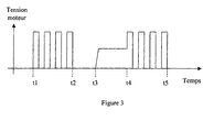
- control circuit emits a power supply signal of the electric motor and is adapted to perform a measurement of the motor speed by processing said supply signal.
- control circuit is adapted to perform said speed measurement during time intervals where the current is zero, in the hash periods.
- the measurement of the speed is not performed when the operation of the chopper prevents the immediate availability of this information. Said measurement is made differently on the motor on the analog-digital converter inputs of a microcontroller.
- control circuit is adapted to integrate said speed measurement over time to determine the instantaneous position of the motor.
- control circuit is adapted to compare said instantaneous position with a reference value which depends on the signal delivered by the Hall effect sensor.
- control circuit is adapted to perform a proportional-integral-derivative type correction on the result of said comparison.
- a cutting tool 10 such as, for example, a powered secateurs, which comprises cutting members 12A and 12B in the form of cutting blades (the word “blade” also covering the notion of hook) actuated by a drive member 13, from the actuation of a trigger 14 provided on the tool 10.
- the manual action on the trigger 14, having a pivoting ability, provides control of the motor member 13, via an electronic circuit 19 powered by a power source 15.
- This pruner 10 comprises a recessed body 11 whose rear portion 11a is shaped to serve as a handle and on the front part of which is fixed the hook or fixed blade 12B of the cutting head.
- This hollow body 11 is, for example, executed in two parts assembled by screwing, along a longitudinal plane.
- the motor member 13 here an electric motor DC collector coupled to a gear 20 disposed in front of said electric motor 13.
- the output of the gear 20 is coupled to the movable blade 12A.
- the energy source 15 is in the form of electric batteries (not shown, for example housed in a belt-shaped sheath that the user wears at the waist) connected to the electronic circuit 19 by a flexible electric cable 23.
- a return spring 21 recalls the trigger 14 in the open position.
- a permanent magnet 17 is carried by the trigger 14 and a Hall effect sensor 18 is fixed to the body 11 of the cutting tool 10.
- a second permanent magnet 16 is fixed to the body 11 of the cutting tool 10 and the two permanent magnets 16 and 17 are inversely oriented, that is to say that their poles which are facing present the same polarity.
- the Hall effect sensor 18 is located, permanently, between the two magnets 16 and 17.
- the Hall effect sensor 18 is placed on the face of the magnet 16 which is opposite the trigger 14. magnetic field of the fixed magnet 16 interfering with the magnetic field of the magnet 17 supported by the trigger 14.
- the Hall effect sensor output signal 18 is less sensitive to the respective mechanical positioning dispersions of the trigger 14, the magnet 17 supported by the trigger 14 and the Hall effect sensor 18.
- this new cutting tool 10 which is the subject of the present invention, allows an electronically controlled progressive cutting, based on the principle of the use of a Hall effect sensor 18 implementing two permanent magnets 16 and 17. , one of the magnets, 16, being fixed and the other, 17, being movable with the trigger 14 of the cutting tool or pruner 10.
- the appropriate circuit electronics electronic control 19 slaves the position of the movable blade 12A to the position of the trigger 14.
- the response curve of the Hall effect sensor 18 with respect to the position of the magnet supported 17 by the trigger 14 is more linear. Moreover, since the magnets 16 and 17 repel each other, the position user will not be disturbed by an attraction between the magnets.
- the respective positions of the Hall effect sensor 18 and the magnets 16 and 17 ensure that the magnetic field passing through the Hall effect sensor 18 varies by a factor of at least five when the trigger 14 moves between its extreme positions.
- the Hall effect sensor 18 known per se, makes it possible to transform a magnetic field value into a proportional voltage and this without any material contact, which avoids the risk of wear.
- the Hall effect sensor 18 is connected to the electronic circuit 19.
- the electronic circuit 19 is represented in figure 2 connected to the DC-commutated electric motor 13 and to the Hall effect sensor 18. It comprises a chopper circuit 34 and a microcontroller 31 comprising an analog-digital converter (not represented) and digital analog converter inputs 31A, 31B and 31 C, a program memory (not shown) and a non-volatile memory (not shown).
- the microcontroller 31 receives, on the analog-digital converter input 31C, the signal emitted by the Hall effect sensor 18.
- the microcontroller 31 controls the electric motor 13 by means of a controlled control of the chopper 34, as a function of the signal it receives from the Hall effect sensor 18.
- the microcontroller 31 is adapted to perform a motor speed measurement by processing the motor supply signal 13, during particular time intervals in the hash periods (see time diagram illustrated in FIG. figure 3 ).
- a voltage divider bridge formed of four resistor 41 to 44 is connected to the inputs of the motor 13 and, at the output, to the analog-to-digital converter inputs 31A and 31B.
- the microcontroller 31 integrates the measurement of speed in time to determine the instantaneous position of the engine and compares said instantaneous position with a reference value which depends on the signal delivered by the Hall effect sensor 18. Then, the microcontroller 31 performs a proportional-integral-derivative type correction on the result of said comparison.
- the pruner previously described operates as follows: when not in use, the blades 12A and 12B are closed.
- a safety switch 22 controls the powering up of the electronic circuit 19 and the opening of the blades 12A and 12B: when the electronic circuit 19 is powered, the motor 13 starts and drives the blade 12A in the open position. In this situation, the blades 12A and 12B of the pruner 10 are in the fully open position.
- the user presses the trigger 14, which causes a variation of the signal output from the Hall effect sensor 18.
- the motor 13, driven by this signal and the electronic card 19, is restarted, causing the pivoting blade 12A to pivot towards its closed position.
- the movements of the movable blade 12A are completely controlled by the movements of the trigger 14, which ensures total progressivity during opening and, especially, during closing and cutting.
- the movable blade 12A can be immobilized with precision in any intermediate position, both during the opening phase and during the closing phase. For this purpose, the user manually immobilizes the trigger 14 in an intermediate position.
- position control device can be used in combination with other known transmission or motion transformation systems such as: gear, crank-rod, cam, etc.
- the motor 13 is replaced by a stepper motor.
Landscapes
- Life Sciences & Earth Sciences (AREA)
- Forests & Forestry (AREA)
- Ecology (AREA)
- Environmental Sciences (AREA)
- Biodiversity & Conservation Biology (AREA)
- Mechanical Engineering (AREA)
- Engineering & Computer Science (AREA)
- Scissors And Nippers (AREA)
- Manipulator (AREA)
- Devices For Conveying Motion By Means Of Endless Flexible Members (AREA)
- Surgical Instruments (AREA)
- Sawing (AREA)
- Road Repair (AREA)
Claims (12)
- Schneidwerkzeug (10) mit mindestens einem beweglichen Blatt (12A), das durch einen Elektromotor (13) unter der Steuerung durch einen Drücker (14) verschoben wird, dadurch gekennzeichnet, dass es aufweist:- einen Magneten (17), der fest mit dem Drücker (14) verbunden ist,- einen Hall-Effektfühler (18), der das Magnetfeld des vom Drücker getragenen Magneten misst und ein Signal aussendet, das repräsentativ für die augenblickliche Stellung des Drückers ist, und- einen Steuerkreis (19) des Elektromotors, der dafür eingerichtet ist, den Betrieb des Motors (13) in Abhängigkeit von dem für die augenblickliche Stellung des Drückers (14) repräsentativen Signal zu steuern,wobei der Motor (13) das Entfernen (Öffnen) des beweglichen Blatts (12A) bewirkt, wenn der Drücker (14) sich in einer ersten Verschiebungsrichtung verschiebt, und das Anziehen (Schließen) des beweglichen Blatts (12A) bewirkt, wenn der Drücker (14) sich in einer zweiten Verschiebungsrichtung verschiebt, die der ersten Verschiebungsrichtung entgegengesetzt ist.
- Schneidwerkzeug nach Anspruch 1, dadurch gekennzeichnet, dass es einen Magneten (16) aufweist, der bezüglich des Hall-Effektfühlers (18) fest ist, wobei das Magnetfeld des festen Magneten (16) mit dem Magnetfeld des vom Drücker getragenen Magneten (17) interferiert.
- Schneidwerkzeug nach Anspruch 2, dadurch gekennzeichnet, dass der Fühler (18) zwischen den zwei Magneten (16, 17) angeordnet ist und die zwei Magnete entgegengesetzt montiert sind, d.h. dass ihre einander gegenüberliegenden Pole identisch sind.
- Schneidwerkzeug nach einem der Ansprüche 1 bis 3, dadurch gekennzeichnet, dass der Fühler (18) und die Magnete (16, 17) so angeordnet sind, dass das den Fühler durchsetzende Magnetfeld sich um einen Faktor von mindestens gleich fünf verändert, wenn der Drücker sich zwischen seinen Endstellungen verschiebt.
- Schneidwerkzeug nach einem der Ansprüche 1 bis 4, dadurch gekennzeichnet, dass der Elektromotor (13) vom Typ Kollektormotor ist.
- Schneidwerkzeug nach einem der Ansprüche 1 bis 5, dadurch gekennzeichnet, dass der Steuerkreis (19) den Elektromotor (13) über den Strom steuert.
- Schneidwerkzeug nach einem der Ansprüche 1 bis 6, dadurch gekennzeichnet, dass der Steuerkreis (19) dafür eingerichtet ist, den Elektromotor (13) mittels einer Steuerung durch Zerhacker (34) zu steuern.
- Schneidwerkzeug nach einem der Ansprüche 1 bis 7, dadurch gekennzeichnet, dass der Steuerkreis (19) ein Signal zur Speisung des Elektromotors aussendet und dafür eingerichtet ist, eine Messung der Geschwindigkeit des Motors durch Behandlung dieses Speisesignals zu bewirken.
- Schneidwerkzeug nach den Ansprüchen 7 und 8, dadurch gekennzeichnet, dass der Steuerkreis (19) dafür eingerichtet ist, die Messung der Geschwindigkeit in den Zerhackerperioden während Zeitintervallen durchzuführen, wo der Strom Null ist.
- Schneidwerkzeug nach einem der Ansprüche 8 oder 9, dadurch gekennzeichnet, dass der Steuerkreis (19) dafür eingerichtet ist, die Messung der Geschwindigkeit in der Zeit zu integrieren, um die augenblickliche Stellung des Motors zu bestimmen.
- Schneidwerkzeug nach Anspruch 10, dadurch gekennzeichnet, dass der Steuerkreis (19) dafür eingerichtet ist, die augenblickliche Stellung mit einem Einstellwert zu vergleichen, der von dem vom Hall-Effektfühler (18) gelieferten Signal abhängt.
- Schneidwerkzeug nach Anspruch 11, dadurch gekennzeichnet, dass der Steuerkreis (19) dafür eingerichtet ist, eine Korrektur vom Typ Proportional-Integral-Differentialquotient am Resultat des Vergleichs durchzuführen.
Applications Claiming Priority (2)
| Application Number | Priority Date | Filing Date | Title |
|---|---|---|---|
| FR0402533 | 2004-03-11 | ||
| FR0402533A FR2867408B1 (fr) | 2004-03-11 | 2004-03-11 | Dispositif de couple electroniquement asservi. |
Publications (2)
| Publication Number | Publication Date |
|---|---|
| EP1574125A1 EP1574125A1 (de) | 2005-09-14 |
| EP1574125B1 true EP1574125B1 (de) | 2008-04-09 |
Family
ID=34814570
Family Applications (1)
| Application Number | Title | Priority Date | Filing Date |
|---|---|---|---|
| EP05352004A Expired - Lifetime EP1574125B1 (de) | 2004-03-11 | 2005-02-25 | Elektronisch geregeltes Schneidwerkzeug |
Country Status (5)
| Country | Link |
|---|---|
| EP (1) | EP1574125B1 (de) |
| AT (1) | ATE391414T1 (de) |
| DE (1) | DE602005005884D1 (de) |
| ES (1) | ES2306058T3 (de) |
| FR (1) | FR2867408B1 (de) |
Cited By (3)
| Publication number | Priority date | Publication date | Assignee | Title |
|---|---|---|---|---|
| ES2382279A1 (es) * | 2009-08-10 | 2012-06-06 | Bellota Herramientas S.A.U | Dispositivo electrico de corte |
| ITPD20130121A1 (it) * | 2013-05-07 | 2014-11-08 | Zanon S R L | Cesoia elettrica |
| DE102010028228B4 (de) | 2009-04-28 | 2018-05-09 | Chervon (Hk) Ltd. | Control Method for Motor-Driven Shears |
Families Citing this family (14)
| Publication number | Priority date | Publication date | Assignee | Title |
|---|---|---|---|---|
| ES2268954B1 (es) * | 2005-01-27 | 2008-03-01 | Josep Gurri Molins | Util de corte motorizado portatil. |
| JP5034348B2 (ja) * | 2006-07-20 | 2012-09-26 | マックス株式会社 | 電動式ハサミ |
| FR2957834B1 (fr) | 2010-03-24 | 2012-03-09 | Infaco | Dispositif de controle positionnel de deux elements l'un par rapport a l'autre tel que lames d'outils de coupe du genre secateur et outil de coupe le comportant |
| HUE052757T2 (hu) * | 2010-10-04 | 2021-05-28 | Husqvarna Ab | Kézi mûködtetésû kerti olló |
| CN102388753B (zh) * | 2011-07-14 | 2013-07-31 | 南京德朔实业有限公司 | 切割工具的刀齿重叠控制系统及其控制方法 |
| ES2538673T5 (es) | 2012-05-04 | 2022-05-04 | Felco Sa | Utensilio electro-portátil |
| ES2658617T3 (es) * | 2013-09-26 | 2018-03-12 | Ningbo Zhenhai Greatwall Automobile Parts Factory | Dispositivo de corte de árboles eléctrico |
| CN103609253A (zh) * | 2013-11-02 | 2014-03-05 | 欧解利 | 万寿菊摘花机 |
| BR112020008692A2 (pt) * | 2017-11-23 | 2020-10-27 | Pellenc | dispositivo de comando, para ferramenta motorizada e ferramenta segura que compreende um tal dispositivo de comando |
| EP3822031A1 (de) * | 2019-11-14 | 2021-05-19 | Hilti Aktiengesellschaft | Verfahren zum steuern und regeln einer werkzeugmaschine |
| EP3858561A1 (de) * | 2020-01-29 | 2021-08-04 | Husqvarna Ab | Schneidwerkzeug |
| CN115362841A (zh) * | 2022-09-03 | 2022-11-22 | 东莞市嘉航实业有限公司 | 一种电动剪切工具的剪切开度控制方法 |
| CN116214585B (zh) * | 2022-09-07 | 2026-04-28 | 深圳绿威科技有限公司 | 一种电剪刀自适应控制方法及电剪刀 |
| CN117256339B (zh) * | 2023-11-14 | 2024-11-26 | 东莞市嘉航实业有限公司 | 一种中、远距离剪切装置及控制方法 |
Family Cites Families (3)
| Publication number | Priority date | Publication date | Assignee | Title |
|---|---|---|---|---|
| FR2469112A1 (fr) * | 1979-11-13 | 1981-05-22 | Pellenc & Motte | Secateur hydraulique a asservissement en position |
| FR2614568B1 (fr) * | 1987-04-28 | 1989-07-28 | Pellenc & Motte | Outil electrique portable a asservissement en position |
| JP3537649B2 (ja) * | 1997-10-30 | 2004-06-14 | 株式会社マキタ | 電動式せん定はさみ |
-
2004
- 2004-03-11 FR FR0402533A patent/FR2867408B1/fr not_active Expired - Fee Related
-
2005
- 2005-02-25 EP EP05352004A patent/EP1574125B1/de not_active Expired - Lifetime
- 2005-02-25 DE DE602005005884T patent/DE602005005884D1/de not_active Expired - Lifetime
- 2005-02-25 ES ES05352004T patent/ES2306058T3/es not_active Expired - Lifetime
- 2005-02-25 AT AT05352004T patent/ATE391414T1/de not_active IP Right Cessation
Cited By (3)
| Publication number | Priority date | Publication date | Assignee | Title |
|---|---|---|---|---|
| DE102010028228B4 (de) | 2009-04-28 | 2018-05-09 | Chervon (Hk) Ltd. | Control Method for Motor-Driven Shears |
| ES2382279A1 (es) * | 2009-08-10 | 2012-06-06 | Bellota Herramientas S.A.U | Dispositivo electrico de corte |
| ITPD20130121A1 (it) * | 2013-05-07 | 2014-11-08 | Zanon S R L | Cesoia elettrica |
Also Published As
| Publication number | Publication date |
|---|---|
| FR2867408B1 (fr) | 2006-05-19 |
| EP1574125A1 (de) | 2005-09-14 |
| ES2306058T3 (es) | 2008-11-01 |
| FR2867408A1 (fr) | 2005-09-16 |
| DE602005005884D1 (de) | 2008-05-21 |
| ATE391414T1 (de) | 2008-04-15 |
Similar Documents
| Publication | Publication Date | Title |
|---|---|---|
| FR2867408A1 (fr) | Dispositif de couple electroniquement asservi. | |
| EP2550135B1 (de) | Vorrichtung zur steuerung der relativen positionierung von zwei elementen, wie etwa den klingen eines schneidwerkzeugs vom rosenscherentyp sowie schneidwerkzeug damit | |
| EP2156732B1 (de) | Tragbares Elektrowerkzeug mit Auslöser | |
| CA1330162C (fr) | Outil electrique portable a asservissement en position | |
| CA2734837C (fr) | Dispositif de securite pour outil portatif a moteur thermique | |
| FR2939008A1 (fr) | Appareil de taille motorise auto-decoincant, en particulier taille-haie | |
| EP0057338B1 (de) | Steuergerät für den Antriebsmotor einer Schiebewand eines Kraftfahrzeuges, insbesondere für eine Fensterhebeanlage | |
| FR2514162A1 (fr) | Servomecanisme et procede pour commander automatiquement la vitesse de vehicules | |
| EP3225100B1 (de) | Tragbares motorisiertes elektrisches schneidewerkzeug vom typ gartenschere | |
| CA2825056A1 (fr) | Dispositif d'actionnement d'un equipement pilotable automatiquement ou manuellement avec detection de la reprise du pilotage manuel | |
| EP2363950B1 (de) | Betätigungssystem mit Schrittschaltmotor | |
| WO2002028167A1 (fr) | Appareil pour la pose automatique de liens torsades | |
| EP2054200B1 (de) | Werkzeug mit hilfsvorrichtung zur betätigung | |
| FR2766158A1 (fr) | Procede et dispositif d'aide au controle, par le pilote, des limitations de puissance du ou des turbomoteurs et/ou du regime rotor des helicopteres thermopropulses | |
| FR2500043A1 (fr) | Dispositif de commande electrique d'un organe d'actionnement | |
| EP3768069B1 (de) | Vorrichtung zum anbringen von drahtbefestigungselementen | |
| EP0209481B1 (de) | Automatische Schere zum Schneiden von Reben, Bäumen und dergleichen | |
| FR2667044A1 (fr) | Verin de trim pour commande de lacet d'un helicoptere. | |
| EP1804709B1 (de) | Drehbare feilenvorrichtung zur zahnbehandlung | |
| FR2741651A1 (fr) | Dispositif assurant l'arret automatique et la synchronisation de volets battants motorises a l'ouverture et a la fermeture | |
| EP0220995A1 (de) | Unabhängige elektrisch angetriebene Schere | |
| EP4085749B1 (de) | Elektrische und tragbare gartenschere | |
| FR3145305A1 (fr) | Cisaille électrique | |
| FR2956528A1 (fr) | Procede de recuperation d'energie electrique sur les moteurs a courant continu |
Legal Events
| Date | Code | Title | Description |
|---|---|---|---|
| PUAI | Public reference made under article 153(3) epc to a published international application that has entered the european phase |
Free format text: ORIGINAL CODE: 0009012 |
|
| AK | Designated contracting states |
Kind code of ref document: A1 Designated state(s): AT BE BG CH CY CZ DE DK EE ES FI FR GB GR HU IE IS IT LI LT LU MC NL PL PT RO SE SI SK TR |
|
| AX | Request for extension of the european patent |
Extension state: AL BA HR LV MK YU |
|
| 17P | Request for examination filed |
Effective date: 20051228 |
|
| AKX | Designation fees paid |
Designated state(s): AT BE BG CH CY CZ DE DK EE ES FI FR GB GR HU IE IS IT LI LT LU MC NL PL PT RO SE SI SK TR |
|
| GRAP | Despatch of communication of intention to grant a patent |
Free format text: ORIGINAL CODE: EPIDOSNIGR1 |
|
| GRAS | Grant fee paid |
Free format text: ORIGINAL CODE: EPIDOSNIGR3 |
|
| GRAA | (expected) grant |
Free format text: ORIGINAL CODE: 0009210 |
|
| AK | Designated contracting states |
Kind code of ref document: B1 Designated state(s): AT BE BG CH CY CZ DE DK EE ES FI FR GB GR HU IE IS IT LI LT LU MC NL PL PT RO SE SI SK TR |
|
| REG | Reference to a national code |
Ref country code: GB Ref legal event code: FG4D Free format text: NOT ENGLISH |
|
| REG | Reference to a national code |
Ref country code: CH Ref legal event code: EP |
|
| REG | Reference to a national code |
Ref country code: IE Ref legal event code: FG4D Free format text: LANGUAGE OF EP DOCUMENT: FRENCH |
|
| REF | Corresponds to: |
Ref document number: 602005005884 Country of ref document: DE Date of ref document: 20080521 Kind code of ref document: P |
|
| PG25 | Lapsed in a contracting state [announced via postgrant information from national office to epo] |
Ref country code: SI Free format text: LAPSE BECAUSE OF FAILURE TO SUBMIT A TRANSLATION OF THE DESCRIPTION OR TO PAY THE FEE WITHIN THE PRESCRIBED TIME-LIMIT Effective date: 20080409 |
|
| NLV1 | Nl: lapsed or annulled due to failure to fulfill the requirements of art. 29p and 29m of the patents act | ||
| PG25 | Lapsed in a contracting state [announced via postgrant information from national office to epo] |
Ref country code: NL Free format text: LAPSE BECAUSE OF FAILURE TO SUBMIT A TRANSLATION OF THE DESCRIPTION OR TO PAY THE FEE WITHIN THE PRESCRIBED TIME-LIMIT Effective date: 20080409 Ref country code: FI Free format text: LAPSE BECAUSE OF FAILURE TO SUBMIT A TRANSLATION OF THE DESCRIPTION OR TO PAY THE FEE WITHIN THE PRESCRIBED TIME-LIMIT Effective date: 20080409 Ref country code: PT Free format text: LAPSE BECAUSE OF FAILURE TO SUBMIT A TRANSLATION OF THE DESCRIPTION OR TO PAY THE FEE WITHIN THE PRESCRIBED TIME-LIMIT Effective date: 20080910 Ref country code: BG Free format text: LAPSE BECAUSE OF FAILURE TO SUBMIT A TRANSLATION OF THE DESCRIPTION OR TO PAY THE FEE WITHIN THE PRESCRIBED TIME-LIMIT Effective date: 20080709 |
|
| REG | Reference to a national code |
Ref country code: ES Ref legal event code: FG2A Ref document number: 2306058 Country of ref document: ES Kind code of ref document: T3 |
|
| PG25 | Lapsed in a contracting state [announced via postgrant information from national office to epo] |
Ref country code: PL Free format text: LAPSE BECAUSE OF FAILURE TO SUBMIT A TRANSLATION OF THE DESCRIPTION OR TO PAY THE FEE WITHIN THE PRESCRIBED TIME-LIMIT Effective date: 20080409 Ref country code: AT Free format text: LAPSE BECAUSE OF FAILURE TO SUBMIT A TRANSLATION OF THE DESCRIPTION OR TO PAY THE FEE WITHIN THE PRESCRIBED TIME-LIMIT Effective date: 20080409 |
|
| REG | Reference to a national code |
Ref country code: IE Ref legal event code: FD4D |
|
| PG25 | Lapsed in a contracting state [announced via postgrant information from national office to epo] |
Ref country code: IS Free format text: LAPSE BECAUSE OF FAILURE TO SUBMIT A TRANSLATION OF THE DESCRIPTION OR TO PAY THE FEE WITHIN THE PRESCRIBED TIME-LIMIT Effective date: 20080809 |
|
| PG25 | Lapsed in a contracting state [announced via postgrant information from national office to epo] |
Ref country code: SE Free format text: LAPSE BECAUSE OF FAILURE TO SUBMIT A TRANSLATION OF THE DESCRIPTION OR TO PAY THE FEE WITHIN THE PRESCRIBED TIME-LIMIT Effective date: 20080709 Ref country code: LT Free format text: LAPSE BECAUSE OF FAILURE TO SUBMIT A TRANSLATION OF THE DESCRIPTION OR TO PAY THE FEE WITHIN THE PRESCRIBED TIME-LIMIT Effective date: 20080409 Ref country code: CZ Free format text: LAPSE BECAUSE OF FAILURE TO SUBMIT A TRANSLATION OF THE DESCRIPTION OR TO PAY THE FEE WITHIN THE PRESCRIBED TIME-LIMIT Effective date: 20080409 Ref country code: IE Free format text: LAPSE BECAUSE OF FAILURE TO SUBMIT A TRANSLATION OF THE DESCRIPTION OR TO PAY THE FEE WITHIN THE PRESCRIBED TIME-LIMIT Effective date: 20080409 Ref country code: DK Free format text: LAPSE BECAUSE OF FAILURE TO SUBMIT A TRANSLATION OF THE DESCRIPTION OR TO PAY THE FEE WITHIN THE PRESCRIBED TIME-LIMIT Effective date: 20080409 |
|
| PLBE | No opposition filed within time limit |
Free format text: ORIGINAL CODE: 0009261 |
|
| STAA | Information on the status of an ep patent application or granted ep patent |
Free format text: STATUS: NO OPPOSITION FILED WITHIN TIME LIMIT |
|
| PG25 | Lapsed in a contracting state [announced via postgrant information from national office to epo] |
Ref country code: RO Free format text: LAPSE BECAUSE OF FAILURE TO SUBMIT A TRANSLATION OF THE DESCRIPTION OR TO PAY THE FEE WITHIN THE PRESCRIBED TIME-LIMIT Effective date: 20080409 Ref country code: SK Free format text: LAPSE BECAUSE OF FAILURE TO SUBMIT A TRANSLATION OF THE DESCRIPTION OR TO PAY THE FEE WITHIN THE PRESCRIBED TIME-LIMIT Effective date: 20080409 |
|
| 26N | No opposition filed |
Effective date: 20090112 |
|
| PG25 | Lapsed in a contracting state [announced via postgrant information from national office to epo] |
Ref country code: EE Free format text: LAPSE BECAUSE OF FAILURE TO SUBMIT A TRANSLATION OF THE DESCRIPTION OR TO PAY THE FEE WITHIN THE PRESCRIBED TIME-LIMIT Effective date: 20080409 Ref country code: DE Free format text: LAPSE BECAUSE OF FAILURE TO SUBMIT A TRANSLATION OF THE DESCRIPTION OR TO PAY THE FEE WITHIN THE PRESCRIBED TIME-LIMIT Effective date: 20080710 |
|
| BERE | Be: lapsed |
Owner name: INFACO S.A.S Effective date: 20090228 |
|
| PG25 | Lapsed in a contracting state [announced via postgrant information from national office to epo] |
Ref country code: CY Free format text: LAPSE BECAUSE OF FAILURE TO SUBMIT A TRANSLATION OF THE DESCRIPTION OR TO PAY THE FEE WITHIN THE PRESCRIBED TIME-LIMIT Effective date: 20080409 Ref country code: MC Free format text: LAPSE BECAUSE OF NON-PAYMENT OF DUE FEES Effective date: 20090228 |
|
| REG | Reference to a national code |
Ref country code: CH Ref legal event code: PL |
|
| GBPC | Gb: european patent ceased through non-payment of renewal fee |
Effective date: 20090225 |
|
| PG25 | Lapsed in a contracting state [announced via postgrant information from national office to epo] |
Ref country code: LI Free format text: LAPSE BECAUSE OF NON-PAYMENT OF DUE FEES Effective date: 20090228 Ref country code: CH Free format text: LAPSE BECAUSE OF NON-PAYMENT OF DUE FEES Effective date: 20090228 |
|
| PG25 | Lapsed in a contracting state [announced via postgrant information from national office to epo] |
Ref country code: BE Free format text: LAPSE BECAUSE OF NON-PAYMENT OF DUE FEES Effective date: 20090228 |
|
| PG25 | Lapsed in a contracting state [announced via postgrant information from national office to epo] |
Ref country code: GB Free format text: LAPSE BECAUSE OF NON-PAYMENT OF DUE FEES Effective date: 20090225 |
|
| PG25 | Lapsed in a contracting state [announced via postgrant information from national office to epo] |
Ref country code: GR Free format text: LAPSE BECAUSE OF FAILURE TO SUBMIT A TRANSLATION OF THE DESCRIPTION OR TO PAY THE FEE WITHIN THE PRESCRIBED TIME-LIMIT Effective date: 20080710 |
|
| PG25 | Lapsed in a contracting state [announced via postgrant information from national office to epo] |
Ref country code: IT Free format text: LAPSE BECAUSE OF NON-PAYMENT OF DUE FEES Effective date: 20100225 |
|
| PG25 | Lapsed in a contracting state [announced via postgrant information from national office to epo] |
Ref country code: LU Free format text: LAPSE BECAUSE OF NON-PAYMENT OF DUE FEES Effective date: 20090225 |
|
| PG25 | Lapsed in a contracting state [announced via postgrant information from national office to epo] |
Ref country code: HU Free format text: LAPSE BECAUSE OF FAILURE TO SUBMIT A TRANSLATION OF THE DESCRIPTION OR TO PAY THE FEE WITHIN THE PRESCRIBED TIME-LIMIT Effective date: 20081010 |
|
| PGRI | Patent reinstated in contracting state [announced from national office to epo] |
Ref country code: IT Effective date: 20110616 |
|
| PG25 | Lapsed in a contracting state [announced via postgrant information from national office to epo] |
Ref country code: TR Free format text: LAPSE BECAUSE OF FAILURE TO SUBMIT A TRANSLATION OF THE DESCRIPTION OR TO PAY THE FEE WITHIN THE PRESCRIBED TIME-LIMIT Effective date: 20080409 |
|
| REG | Reference to a national code |
Ref country code: FR Ref legal event code: PLFP Year of fee payment: 12 |
|
| REG | Reference to a national code |
Ref country code: FR Ref legal event code: PLFP Year of fee payment: 13 |
|
| PG25 | Lapsed in a contracting state [announced via postgrant information from national office to epo] |
Ref country code: IT Free format text: LAPSE BECAUSE OF NON-PAYMENT OF DUE FEES Effective date: 20170225 |
|
| REG | Reference to a national code |
Ref country code: FR Ref legal event code: PLFP Year of fee payment: 14 |
|
| PG25 | Lapsed in a contracting state [announced via postgrant information from national office to epo] |
Ref country code: IT Free format text: LAPSE BECAUSE OF NON-PAYMENT OF DUE FEES Effective date: 20170225 |
|
| PGRI | Patent reinstated in contracting state [announced from national office to epo] |
Ref country code: IT Effective date: 20180314 |
|
| PGFP | Annual fee paid to national office [announced via postgrant information from national office to epo] |
Ref country code: FR Payment date: 20230224 Year of fee payment: 19 Ref country code: ES Payment date: 20230327 Year of fee payment: 19 |
|
| PGFP | Annual fee paid to national office [announced via postgrant information from national office to epo] |
Ref country code: IT Payment date: 20230223 Year of fee payment: 19 |
|
| PG25 | Lapsed in a contracting state [announced via postgrant information from national office to epo] |
Ref country code: FR Free format text: LAPSE BECAUSE OF NON-PAYMENT OF DUE FEES Effective date: 20240229 |
|
| PG25 | Lapsed in a contracting state [announced via postgrant information from national office to epo] |
Ref country code: FR Free format text: LAPSE BECAUSE OF NON-PAYMENT OF DUE FEES Effective date: 20240229 |
|
| REG | Reference to a national code |
Ref country code: ES Ref legal event code: FD2A Effective date: 20250401 |
|
| PG25 | Lapsed in a contracting state [announced via postgrant information from national office to epo] |
Ref country code: ES Free format text: LAPSE BECAUSE OF NON-PAYMENT OF DUE FEES Effective date: 20240226 |