EP3767940B1 - Linsenhalterung, linsenmodul, und elektronische vorrichtung - Google Patents
Linsenhalterung, linsenmodul, und elektronische vorrichtung Download PDFInfo
- Publication number
- EP3767940B1 EP3767940B1 EP19767858.4A EP19767858A EP3767940B1 EP 3767940 B1 EP3767940 B1 EP 3767940B1 EP 19767858 A EP19767858 A EP 19767858A EP 3767940 B1 EP3767940 B1 EP 3767940B1
- Authority
- EP
- European Patent Office
- Prior art keywords
- lens
- present disclosure
- photosensitive
- displacement
- lens mount
- Prior art date
- Legal status (The legal status is an assumption and is not a legal conclusion. Google has not performed a legal analysis and makes no representation as to the accuracy of the status listed.)
- Active
Links
Images



Classifications
-
- G—PHYSICS
- G02—OPTICS
- G02B—OPTICAL ELEMENTS, SYSTEMS OR APPARATUS
- G02B27/00—Optical systems or apparatus not provided for by any of the groups G02B1/00 - G02B26/00, G02B30/00
- G02B27/64—Imaging systems using optical elements for stabilisation of the lateral and angular position of the image
- G02B27/646—Imaging systems using optical elements for stabilisation of the lateral and angular position of the image compensating for small deviations, e.g. due to vibration or shake
-
- G—PHYSICS
- G03—PHOTOGRAPHY; CINEMATOGRAPHY; ANALOGOUS TECHNIQUES USING WAVES OTHER THAN OPTICAL WAVES; ELECTROGRAPHY; HOLOGRAPHY
- G03B—APPARATUS OR ARRANGEMENTS FOR TAKING PHOTOGRAPHS OR FOR PROJECTING OR VIEWING THEM; APPARATUS OR ARRANGEMENTS EMPLOYING ANALOGOUS TECHNIQUES USING WAVES OTHER THAN OPTICAL WAVES; ACCESSORIES THEREFOR
- G03B17/00—Details of cameras or camera bodies; Accessories therefor
- G03B17/02—Bodies
- G03B17/12—Bodies with means for supporting objectives, supplementary lenses, filters, masks, or turrets
-
- G—PHYSICS
- G03—PHOTOGRAPHY; CINEMATOGRAPHY; ANALOGOUS TECHNIQUES USING WAVES OTHER THAN OPTICAL WAVES; ELECTROGRAPHY; HOLOGRAPHY
- G03B—APPARATUS OR ARRANGEMENTS FOR TAKING PHOTOGRAPHS OR FOR PROJECTING OR VIEWING THEM; APPARATUS OR ARRANGEMENTS EMPLOYING ANALOGOUS TECHNIQUES USING WAVES OTHER THAN OPTICAL WAVES; ACCESSORIES THEREFOR
- G03B5/00—Adjustment of optical system relative to image or object surface other than for focusing
-
- H—ELECTRICITY
- H04—ELECTRIC COMMUNICATION TECHNIQUE
- H04N—PICTORIAL COMMUNICATION, e.g. TELEVISION
- H04N23/00—Cameras or camera modules comprising electronic image sensors; Control thereof
- H04N23/50—Constructional details
- H04N23/54—Mounting of pick-up tubes, electronic image sensors, deviation or focusing coils
-
- H—ELECTRICITY
- H04—ELECTRIC COMMUNICATION TECHNIQUE
- H04N—PICTORIAL COMMUNICATION, e.g. TELEVISION
- H04N23/00—Cameras or camera modules comprising electronic image sensors; Control thereof
- H04N23/50—Constructional details
- H04N23/55—Optical parts specially adapted for electronic image sensors; Mounting thereof
-
- H—ELECTRICITY
- H04—ELECTRIC COMMUNICATION TECHNIQUE
- H04N—PICTORIAL COMMUNICATION, e.g. TELEVISION
- H04N23/00—Cameras or camera modules comprising electronic image sensors; Control thereof
- H04N23/60—Control of cameras or camera modules
- H04N23/68—Control of cameras or camera modules for stable pick-up of the scene, e.g. compensating for camera body vibrations
- H04N23/682—Vibration or motion blur correction
- H04N23/685—Vibration or motion blur correction performed by mechanical compensation
- H04N23/687—Vibration or motion blur correction performed by mechanical compensation by shifting the lens or sensor position
-
- G—PHYSICS
- G03—PHOTOGRAPHY; CINEMATOGRAPHY; ANALOGOUS TECHNIQUES USING WAVES OTHER THAN OPTICAL WAVES; ELECTROGRAPHY; HOLOGRAPHY
- G03B—APPARATUS OR ARRANGEMENTS FOR TAKING PHOTOGRAPHS OR FOR PROJECTING OR VIEWING THEM; APPARATUS OR ARRANGEMENTS EMPLOYING ANALOGOUS TECHNIQUES USING WAVES OTHER THAN OPTICAL WAVES; ACCESSORIES THEREFOR
- G03B2205/00—Adjustment of optical system relative to image or object surface other than for focusing
- G03B2205/0007—Movement of one or more optical elements for control of motion blur
-
- G—PHYSICS
- G03—PHOTOGRAPHY; CINEMATOGRAPHY; ANALOGOUS TECHNIQUES USING WAVES OTHER THAN OPTICAL WAVES; ELECTROGRAPHY; HOLOGRAPHY
- G03B—APPARATUS OR ARRANGEMENTS FOR TAKING PHOTOGRAPHS OR FOR PROJECTING OR VIEWING THEM; APPARATUS OR ARRANGEMENTS EMPLOYING ANALOGOUS TECHNIQUES USING WAVES OTHER THAN OPTICAL WAVES; ACCESSORIES THEREFOR
- G03B2205/00—Adjustment of optical system relative to image or object surface other than for focusing
- G03B2205/0053—Driving means for the movement of one or more optical element
- G03B2205/0076—Driving means for the movement of one or more optical element using shape memory alloys
Definitions
- Embodiments of the present disclosure relate to the field of optical technology, and in particular to a lens mount, a lens module and an electronic device.
- a voice coil motor can be installed in the electronic device and enable the voice coil motor to drive a lens of the electronic device to move, thereby reducing an impact of the shaking of the electronic device on the clarity of the captured image (this function can be called optical image stabilization).
- this function can be called optical image stabilization.
- a lens a is secured to a voice coil motor b, and when an outside force is exerted on the lens, it will move in a direction perpendicular to a direction of an optical axis of the lens a (e.g., a direction A1 or B1 as shown in FIG. 1 ).
- the electronic device can control the voice coil motor b to drive the lens a to move in an opposite direction (e.g., the direction B1 or A1 as shown in FIG. 1 ) to the above direction.
- an opposite direction e.g., the direction B1 or A1 as shown in FIG. 1
- optical image stabilization can be achieved.
- the voice coil motor be installed in the electronic device to drive the lens to move, the lens may vibrate slightly which may reduce the reliability of the lens that is usually a precision member.
- WO 2017/072525 A1 discloses a camera assembly including a support structure and an image sensor mounted on a carrier that is suspended on the support structure.
- US 2017/289455 A1 discloses a camera module disposed in an electronic device, including a base, a holder, an image sensor, a bottom, and a first biasing element.
- US 9681052 B1 discloses a system related to optical image stabilization in mobile computing devices that include multiple optical element sets.
- the present disclosure provides a lens module according to claim 12 and further detailed in the dependent claim referring back to this claim.
- the present disclosure provides an electronic device according to claim 14.
- a term "and/or” herein refers to an association relationship that describes associated objects, and means that there may be three relationships.
- a and/or B may mean the following three cases: A exists alone, both A and B exist, and B exists alone.
- the symbol "/" herein represents a "or" relationship of the associated objects.
- A/B means A or B.
- first, second and the like in the specification and claims of the present disclosure are used to distinguish different objects, rather than to describe a specific order of the objects.
- first displacement and the second displacement are used to indicate different displacements, rather than to describe a specific order of the displacements.
- words such as “exemplarily” or “for example” are used to introduce examples, exemplifications, or illustrations. Any embodiment or design solution introduced by means of such words “exemplarily” or “for example” in the present disclosure should not be construed as being more preferable or advantageous than the other embodiments or design solutions. To be precise, the words such as “exemplarily” or “for example” are intended to present a relevant concept in a concrete manner.
- a voice coil motor a device that uses an interaction between magnetic poles in a magnetic field from a permanent magnet and a magnetic field generated by an energized coil conductor to produce regular movement, that is, a power device that can convert electrical energy into mechanical energy.
- a lens an optical device composed of a plurality of lens elements.
- An optical axis of the lens a line connecting centers of the plurality of lens elements in the lens.
- Optical image stabilization a function of reducing an impact of shakiness in a user's hand on the clarity of a captured image when the user is capturing the image using an electronic device having an image capturing function, by providing a special structure in the electronic device.
- a shape memory alloy (Shape Memory Alloy, SMA): an alloy material that can eliminate its deformation generated at a lower temperature and restore its original shape after being heated to make its temperature increased, that is, an alloy with a "memory” effect.
- a rigid-flex board a wiring board having characteristics of both a flexible wiring board and a rigid wiring board, formed by combining the flexible wiring board and the rigid wiring board which have been subjected to lamination or other processes, according to relevant process requirements.
- a filter an optical device used to select a required radiation band.
- Embodiments of the present disclosure provide a lens mount, a lens module, and an electronic device.
- the lens mount can be configured to carry a lens.
- the lens mount can include a photosensitive structure and a driving structure arranged on a first side, distal to the lens, of the photosensitive structure and connected to the photosensitive structure.
- the driving structure can be configured to drive the photosensitive structure to move a second displacement (a direction of the second displacement is in a same plane as and opposite to the direction of the first displacement) if the photosensitive structure moves a first displacement (a direction of the first displacement is perpendicular to a direction of an optical axis of the lens).
- the driving structure in the lens mount can drive the photosensitive structure to move in the direction opposite to the direction of the first displacement, so that the lens mount of this embodiment of the present disclosure can achieve optical image stabilization.
- the embodiment of the present disclosure achieves the optical image stabilization by the driving structure which drives the photosensitive structure to move and thus will not affect the lens, as compared with the related art in which the optical image stabilization is achieved by the voice coil motor which drives the lens to move. Therefore, the embodiment of the present disclosure can ensure the reliability of the lens while achieving the optical image stabilization.
- an embodiment of the present disclosure provides a lens mount 01.
- the lens mount 01 can be configured to carry a lens 00, and includes a photosensitive structure 02, and a driving structure 03 arranged on a first side of the photosensitive structure 02 and connected to the photosensitive structure 02, and the first side of the photosensitive structure 02 is distal to the lens 00.
- the driving structure 03 can be configured to drive the photosensitive structure 02 to move a second displacement when the photosensitive structure 02 moves a first displacement in a direction which is perpendicular to a direction of an optical axis of the lens 00. Moreover, a direction of the second displacement is in a same plane as and opposite to the direction of the first displacement.
- the direction of the first displacement may be indicated as A2, and the direction of the second displacement may be indicated as B2.
- the first displacement may be a distance that the photosensitive structure 02 moves in the direction A2
- the second displacement may be a distance that the photosensitive structure 02 moves in the direction B2.
- the photosensitive structure in the lens mount may move a distance in the direction perpendicular to the direction of the optical axis of the lens (the photosensitive structure moves the first displacement).
- the driving structure may drive the photosensitive structure to move in a direction which is in a same plane as and opposite to the direction of the first displacement (the photosensitive structure moves the second displacement), so that the clarity of the captured images or videos can be improved, and the optical image stabilization can be achieved.
- magnitudes of the first displacement and the second displacement may be the same or different, and this can be based on actual needs, and is not limited in the embodiment of the present disclosure. It will be understood that, the magnitudes of the first displacement and the second displacement may be the same in order to better achieve the optical image stabilization; in addition, the magnitudes of the first displacement and the second displacement may be different since there may be a certain deviation between the magnitudes of the first displacement and the second displacement in practical applications.
- the driving structure in the lens mount can drive the photosensitive structure to move in the direction opposite to the direction of the first displacement, so that the lens mount of this embodiment of the present disclosure can achieve optical image stabilization.
- the embodiment of the present disclosure achieves the optical image stabilization by the driving structure which drives the photosensitive structure to move and thus will not affect the lens, as compared with the related art in which the optical image stabilization is achieved by the voice coil motor which drives the lens to move. Therefore, the embodiment of the present disclosure can ensure the reliability of the lens while achieving the optical image stabilization.
- the driving structure 03 can be further configured to drive the photosensitive structure 02 to move along a first direction, which is the same as the direction of the optical axis of the lens.
- the driving structure can drive the photosensitive structure to move in the first direction under the control of a control signal.
- the first direction may be indicated as C as shown in FIG. 2 .
- the driving structure may receive a control signal sent by a processor (for example, the control signal may be a signal sent by the processor to adjust a focal length of the lens (that is, to adjust an object distance and an image distance), and under the control of the control signal, the driving structure drive the photosensitive structure to move along the direction of the optical axis of the lens (that is, the first direction), so that optical focusing of the lens can be achieved.
- the control signal may be a signal sent by the processor to adjust a focal length of the lens (that is, to adjust an object distance and an image distance)
- the driving structure under the control of the control signal, the driving structure drive the photosensitive structure to move along the direction of the optical axis of the lens (that is, the first direction), so that optical focusing of the lens can be achieved.
- the driving structure can drive the photosensitive structure to move away from the lens along the direction of the optical axis of the lens (that is, the first direction), or the driving structure may drive the photosensitive structure to move towards the lens along the direction of the optical axis of the lens (that is, the first direction).
- the driving structure drives the photosensitive structure to move away from the lens along the direction of the optical axis of the lens, the focal length can be increased; and when the driving structure drives the photosensitive structure to move towards the lens along the direction of the optical axis of the lens, the focus length can be reduced.
- a specific direction in which the photosensitive structure is driven to move can be based on actual needs, and it is not limited in the embodiment of the present disclosure.
- the driving structure can drive the photosensitive structure to move along the direction of the optical axis of the lens (that is, the first direction), so that the object distance and the image distance can be changed to make the taken image of the object clearer, thereby achieving optical focusing.
- the embodiment of the present disclosure achieves the optical focusing by the driving structure which drives the photosensitive structure to move, and thus will not affect the lens, as compared with the related art in which the optical focusing is achieved by the voice coil motor which drives the lens to move.
- the embodiment of the present disclosure can ensure the reliability of the lens while achieving the optical focusing.
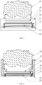
- the driving structure 03 shown in FIG. 2 may include a first wiring board 04, M connecting members 05, and N deformable members 06.
- Each connecting member 05 has a first end connected to the first wiring board 04, and a second end connected to the photosensitive structure 02.
- the N deformable members 06 are all located between the first wiring board 04 and the photosensitive structure 02, and each deformable member 06 has a first end connected to the first wiring board 04, and a second end connected to the photosensitive structure 02.
- At least one of the N deformable members 06 drives the photosensitive structure 02 to move the second displacement after being heated
- M is an integer greater than 1
- N is a positive integer
- the photosensitive structure in the lens mount moves a distance in a direction perpendicular to the direction of the optical axis of the lens (the photosensitive structure moves the first displacement).
- the processor can acquire data of the first displacement (for example, the processor can acquire the data of the first displacement through a motion sensor provided on the photosensitive structure), and calculate an amount of displacement that needs to be compensated for based on the data of the first displacement, and determine, from the N deformable members, at least one deformable member that can drive the photosensitive structure to move the second displacement after being heated.
- the processor is controlled to energize the at least one deformable member, so that the at least one deformable member is deformed (that is, a shape change occurs) after being energized to generate heat, so as to drive the photosensitive structure to move the second displacement.
- each of the drawings illustrated in the embodiments of the present disclosure is a sectional view of a structure (for example, a sectional view of a lens mount or of a lens module, etc.).
- a structure for example, a sectional view of a lens mount or of a lens module, etc.
- the numbers of the connecting members and the deformable members can be based on actual needs, and they are not limited in the embodiment of the present disclosure.
- the first wiring board may be a flexible circuit board, or a rigid circuit board, or a rigid-flex board. Specifically, it can be based on actual needs, and is not limited in the embodiment of the present disclosure.
- the materials of the M connecting members may be metals, metal alloys or other materials, can be based on actual needs, and are not limited in the embodiments of the present disclosure.
- the materials of the M connecting members may be metallic titanium.
- the materials of the M connecting members may be all the same, may be all different, or may be partially the same. They can be based on actual needs, and are not limited in the embodiments of the present disclosure.
- At least one of the N deformable members can drive the photosensitive structure to move along the direction of the optical axis of the lens (i.e., the first direction) after being heated.
- the lens mount provided by the embodiments of the present disclosure, firstly, when the photosensitive structure in the lens mount moves the first displacement under the effect of an outside force, at least one of the N deformable members in the lens mount can drive the photosensitive structure to move in a direction opposite to the direction of the first displacement after being heated, so that the lens mount of the embodiment of the present disclosure can achieve optical image stabilization.
- the embodiment of the present disclosure achieves the optical image stabilization by the driving structure which drives the photosensitive structure to move and thus will not affect the lens, as compared with the related art in which the optical image stabilization is achieved by the voice coil motor which drives the lens to move.
- the embodiment of the present disclosure adopts a thermal deformation of the at least one deformable member to drive the photosensitive structure to move, and the power consumption of the thermal deformation of the at least one deformable member to drive the photosensitive structure to move is much less than the power consumption of the voice coil motor to drive the lens to move, and the embodiments of the present disclosure can thus reduce the power consumption as compared with the related art which adopts the voice coil motor to drive the lens to move.
- the embodiments of the present disclosure can not only ensure the reliability of the lens, but also reduce the power consumption, while achieving the optical image stabilization.
- the gap between the first wiring board and the photosensitive structure may be s as shown in FIG. 3 .
- the deformable member may be a memory alloy member.
- each of the N deformable members may be a memory alloy member.
- the shape memory alloys may be any one, or a combination of two or more of gold-cadmium alloys, silver-cadmium alloys, copper-zinc alloys, copper-zinc-aluminum alloys, copper-zinc-tin alloys, copper-tin alloys, copper-zinc-gallium alloys, indium-titanium alloys, gold-copper-zinc alloys, iron-platinum alloys, titanium-niobium alloys, uranium-niobium alloys, and iron-manganese-silicon alloys.
- the materials of the N deformable members may be any one, or a combination of two or more of the aforementioned shape memory alloys, and the materials of the N deformable members may be all the same, may be all different, or may be partially the same, and they can be based on actual needs, and are not limited in the embodiments of the present disclosure.
- each of the shape memory alloy wires is located between the first wiring board and the photosensitive structure. Moreover, one end of each shape memory alloy wire is connected to the first wiring board, and the other end of the shape memory alloy wire is connected to the photosensitive structure. If the photosensitive structure moves the first displacement, each shape memory alloy wire can drive the photosensitive structure to move the second displacement after being heated (the direction of the second displacement is in a same plane as and opposite to the direction of the first displacement, and the magnitude of the first displacement can be equal to that of the second displacement).
- the photosensitive structure moves the first displacement under the effect of the external force
- the photosensitive structure can be driven by the memory alloy member to move a second displacement in a direction which is in a same plane as and opposite to the direction of the first displacement, so as to achieve optical image stabilization. Since the cost of the memory alloy member is lower than the cost of the voice coil motor, the embodiments of the present disclosure can reduce the production cost while achieving optical image stabilization.
- the photosensitive structure 02 shown in FIG. 3 may include a second wiring board 07 and a photosensitive member 08 arranged on the second wiring board 07.
- the first side of the photosensitive structure 02 is a side of the second wiring board 07 that is opposite to the photosensitive member 08.
- the second end of each connecting member 05 and the second end of each deformable member 06 are connected to the second wiring board 07.
- the second wiring board may be a flexible circuit board, a rigid circuit board, or a rigid-flex board. Specifically, it can be based on actual needs, and is not limited in the embodiment of the present disclosure.
- the photosensitive member may be bonded to the second wiring board with glue.
- the photosensitive member can be provided on the second wiring board in any other possible way, which is not limited in the embodiment of the present disclosure.
- the photosensitive member may be a photosensitive chip.
- the photosensitive chip may be a charge-coupled device (Charge-Coupled Device, CCD) chip, a complementary metal-oxide semiconductor (Complementary Metal-Oxide Semiconductor, CMOS) chip, or any other member that is photosensitive. In actual implementations, it can be based on actual needs, and is not limited in the embodiment of the present disclosure.
- the above-mentioned photosensitive member is a CCD chip and a plurality of photodiodes is arranged on a surface of the CCD chip.
- the photodiodes on the surface of the CCD chip can sense the light and convert it into an analog electrical signal.
- the analog electrical signal can be then processed by a sampling amplifier circuit and an analog-to-digital conversion circuit, so that the analog electrical signal is converted into a digital image signal.
- the digital image signal can be compressed and stored in a storage device (for example, a flash memory or a built-in hard disk card, etc.) within the electronic device.
- a storage device for example, a flash memory or a built-in hard disk card, etc.
- the lens mount provided by the embodiment of the present disclosure is capable of converting the optical image collected by the lens into an image signal through the second wiring board and the photosensitive member provided on the second wiring board.
- the lens mount 01 provided by the embodiment of the present disclosure may further include a filter 09 provided on a second side of the photosensitive structure, which is a same side of the second wiring board 07 where the photosensitive member 08 is located.
- the filter allows light of a predetermined wavelength to be transmitted through, that is, the filter can be used to filter light of wavelengths other than the predetermined wavelength.
- the filter may be a visible light pass filter, an ultraviolet light pass filter, an infrared light pass filter, or the like.
- the filter is a visible light pass filter
- the visible light pass filter when light in the external environment of the lens passes through the lens elements in the lens to reach the visible light pass filter, the visible light pass filter can absorb light of wavelengths other than visible wavelengths.
- the visible light can pass through the filter and reach the second wiring board of the photosensitive structure.
- the filter is an ultraviolet light pass filter
- the ultraviolet light pass filter when the light in the external environment of the lens passes through the lens elements in the lens to reach the ultraviolet light pass filter, the ultraviolet light pass filter can absorb light of wavelengths other than ultraviolet wavelengths.
- the ultraviolet light can pass through the filter and reach the second wiring board of the photosensitive structure.
- the filter is an infrared light pass filter
- the infrared light pass filter can absorb light of wavelengths other than the infrared wavelengths.
- the infrared light can pass through the filter and reach the second wiring board of the photosensitive structure.
- FIGS. 3, 4 , and 5 a larger gap is illustrated in FIGS. 3, 4 , and 5 in the embodiments of the present disclosure in order to show the gap between the first wiring board and the photosensitive structure more clearly. In actual implementations, it can be based on actual needs, and is not limited in the embodiment of the present disclosure.
- a filter is provided on the second side of the photosensitive structure, and when the light in the external environment of the lens passes through the lens elements in the lens to reach the filter, the filter can allow the light of the predetermined wavelength to pass through and absorb the light of wavelengths other than the predetermined wavelength, so that the photosensitive structure can convert the light of the predetermined wavelength in the optical image into an image signal.
- the lens mount provided by the embodiment of the present disclosure may further include a support structure 10, which may be used to support the lens 00 and secure the filter 09.
- the support structure may be embodied by a structure 10 as shown in FIG. 6 (for example, the structure 10 may be a bracket), or may be embodied by a combination of two substructures (for example, one substructure is used to support the lens, and the other is used to secure the filter, and these two substructures can be bonded together to form a support structure).
- a specific support structure can be based on actual needs, and it is not limited in the embodiments of the present disclosure.
- a size of the gap between the first wiring board and the photosensitive structure is recited by way of example.
- the size of the gap between the first wiring board and the photosensitive structure can be based on actual needs, and it is not limited in the embodiment of the present disclosure.
- the support structure provided on the lens mount can support the lens and secure the filter. Also, the support structure can further seal and protect the first wiring board, the second wiring board, the M connecting members, the N deformable members and the photosensitive member.
- an embodiment of the present disclosure provides a lens module 11.
- the lens module 11 may include a lens 00, and a lens mount which can be used to carry the lens 00.
- the lens mount may include a first wiring board 04, a connecting member 05, a deformable member 06, a second wiring board 07, a photosensitive member 08, a filter 09, and a support structure 10.
- FIG. 7 is an exemplary illustration in which the lens mount shown in FIG. 6 described in the foregoing embodiment is incorporated as an example.
- the lens module provided by the embodiment of the present disclosure may be implemented in combination with the lens mount shown in any one of FIGS. 2 to 5 .
- the lens and the lens mount may be provided with matching threads which can be used to secure the lens to the lens mount.
- An embodiment of the present disclosure provides a lens module, which includes a lens and a lens mount for carrying the lens.
- the driving structure in the lens mount can drive the photosensitive structure to move in the direction opposite to the direction of the first displacement, so that the lens module of this embodiment of the present disclosure can achieve optical image stabilization.
- the embodiment of the present disclosure achieves the optical image stabilization by the driving structure which drives the photosensitive structure to move and thus will not affect the lens, as compared with the related art in which the optical image stabilization is achieved by the voice coil motor which drives the lens to move. Therefore, the embodiment of the present disclosure can ensure the reliability of the lens while achieving the optical image stabilization.
- the lens mount provided by the embodiment of the present disclosure may include a support structure 10, and a radius of the lens module in a second direction (for example, a direction A3 as shown in FIG. 7 ) is a sum of a radius of the lens 00 and a thickness of the support structure 10 in the second direction.
- the second direction is perpendicular to the direction of the optical axis of the lens.
- the second direction A3 shown in FIG. 7 may be the same as, or different from, the direction of the first displacement A2 shown in FIG. 2 .
- the second direction A3 shown in FIG. 7 may be the same as, or different from, the direction of the second displacement B2 shown in FIG. 2 .
- the second direction A3, the direction of the first displacement A2, the direction of the second displacement B2, and the direction of the optical axis of the lens are all recited by way of example, and they are not limited in the embodiment of the present disclosure. In actual implementations, they can be based on actual needs, and are not limited in the embodiment of the present disclosure.
- the radius of the lens module in the second direction shown in FIG. 7 is denoted as D
- the radius of the lens 00 is denoted as d2 as shown in FIG. 7
- a radius of the lens module in the second direction is a sum of a radius of the lens and a thickness of the voice coil motor in the second direction
- the thickness of the voice coil motor in the second direction includes a thickness of the lens carrier and the coil, a thickness of the magnet securing bracket, a thickness of the magnet, the gap between the lens carrier and the magnet securing bracket, an anti-shake translation gap, and the thickness of the voice coil motor.
- the radius of the lens module in the second direction is the sum of the radius of the lens and the thickness of the support structure in the second direction. Since the thickness of the support structure in the second direction is much smaller than the thickness of the voice coil motor in the second direction, the lens module provided by the embodiment of the present disclosure can reduce the radius of the lens module in the second direction as compared with the related art.
- the thickness of the support structure in the second direction may be generally 0.25 mm, while the thickness of the magnet in the voice coil motor provided in the related art is generally from 0.3 mm to 0.35 mm.
- the thickness of the support structure in the second direction in the embodiment of the present disclosure is much smaller than the thickness of the voice coil motor in the second direction in the related art. That is, the lens module provided by the embodiment of the present disclosure can reduce the radius of the lens module in the second direction as compared with the related art.
- the radius of the lens module in the second direction is the sum of the radius of the lens and the thickness of the support structure in the second direction
- the thickness of the support structure in the second direction i.e., a direction perpendicular to the direction of the optical axis of the lens
- the lens module in the embodiment of the present disclosure can reduce the radius of the lens module in the second direction, thereby reducing the side of the lens module in the second direction, as compared with the related art in which the radius of the lens module in the second direction is the sum of the lens and the thickness of the voice coil motor in the second direction.
- An embodiment of the present disclosure provides an electronic device.
- the electronic device may include a lens module.
- the lens module reference may be made to relevant description of the lens module in the above-mentioned embodiment, and the detailed description will not be given here.
- the electronic device may be a mobile terminal, such as a mobile phone, a camera, a camcorder, a tablet computer, a notebook computer, a handheld computer, an in-vehicle terminal, a wearable device, an ultra-mobile personal computer (Ultra-Mobile Personal Computer, UMPC), a netbook, a personal digital assistant (Personal Digital Assistant, PDA), etc.
- a mobile terminal such as a mobile phone, a camera, a camcorder, a tablet computer, a notebook computer, a handheld computer, an in-vehicle terminal, a wearable device, an ultra-mobile personal computer (Ultra-Mobile Personal Computer, UMPC), a netbook, a personal digital assistant (Personal Digital Assistant, PDA), etc.
- UMPC Ultra-mobile Personal Computer
- PDA Personal Digital Assistant
- An embodiment of the present disclosure provides an electronic device, which may include a lens module, and the lens module may include a lens and a lens mount for carrying the lens.
- the driving structure in the lens mount can drive the photosensitive structure to move in the direction opposite to the direction of the first displacement, so that the electronic device of this embodiment of the present disclosure can achieve optical image stabilization.
- the embodiment of the present disclosure achieves the optical image stabilization by the driving structure which drives the photosensitive structure to move and thus will not affect the lens, as compared with the related art in which the optical image stabilization is achieved by the voice coil motor which drives the lens to move. Therefore, the embodiment of the present disclosure can ensure the reliability of the lens while achieving the optical image stabilization.
Landscapes
- Engineering & Computer Science (AREA)
- Multimedia (AREA)
- Signal Processing (AREA)
- Physics & Mathematics (AREA)
- General Physics & Mathematics (AREA)
- Optics & Photonics (AREA)
- Studio Devices (AREA)
- Adjustment Of Camera Lenses (AREA)
- Lens Barrels (AREA)
- Blocking Light For Cameras (AREA)
Claims (14)
- Linsenhalterung (01), die konfiguriert ist, um eine Linse (00) zu tragen, und umfassend eine lichtempfindliche Struktur (02) und eine Antriebsstruktur (03), die auf einer ersten, von der Linse (00) distalen Seite der lichtempfindlichen Struktur (02) angeordnet und mit der lichtempfindlichen Struktur (02) verbunden ist,wobei die Antriebsstruktur (03) eine erste Leiterplatte (04),M Verbindungselemente (05) und N verformbare Elemente (06) umfasst, wobei jedes der M Verbindungselemente (045) ein erstes Ende, das mit der ersten Leiterplatte (04) verbunden ist, und ein zweites Ende, das mit der lichtempfindlichen Struktur (02) verbunden ist, aufweist;wobei sich alle N verformbaren Elemente (06) zwischen der ersten Leiterplatte (04) und der lichtempfindlichen Struktur (02) befinden;wobei die Linsenhalterung (01) dadurch gekennzeichnet ist, dassdie Antriebsstruktur (03) konfiguriert ist, um die lichtempfindliche Struktur (02) anzutreiben, um eine zweite Verlagerung durch mindestens eines derN verformbaren Elemente(06) zu bewirken, die erregt werden, um Wärme zur thermischen Verformung des mindestens einen der N verformbaren Elemente zu erzeugen, wenn die lichtempfindliche Struktur (02) eine erste Verlagerung aufgrund von Erschütterung in einer Richtung senkrecht zu einer Richtung einer optischen Achse der Linse (00) bewegt, wobei eine Richtung der zweiten Verlagerung in einer gleichen Ebene wie und entgegengesetzt zu der Richtung der ersten Verlagerung ist, wobei N eine positive ganze Zahl ist.
- Linsenhalterung (01) nach Anspruch 1, wobei die Antriebsstruktur (03) ferner konfiguriert ist, um die lichtempfindliche Struktur (02) anzutreiben, um sich entlang einer ersten Richtung zu bewegen, die mit der Richtung der optischen Achse der Linse (00) übereinstimmt, und eine Größe der ersten Verlagerung gleich ist wie die der zweiten Verlagerung.
- Linsenhalterung (01) nach Anspruch 1, wobei M eine ganze Zahl größer als 1 ist.
- Linsenhalterung (01) nach Anspruch 1 oder 3, wobei ein Abstand zwischen der ersten Leiterplatte (04) und der lichtempfindlichen Struktur (02) größer ist als ein voreingestellter Wert.
- Linsenhalterung (01) nach Anspruch 1 oder 3, wobei ein Abstand zwischen der ersten Leiterplatte (04) und der lichtempfindlichen Struktur (02) gleich ist wie ein voreingestellter Wert.
- Linsenhalterung (01) nach Anspruch 1 oder 3, wobei das verformbare Element (06) ein Gedächtnislegierungselement ist.
- Linsenhalterung (01) nach Anspruch 1 oder 3, wobei die lichtempfindliche Struktur (02) eine zweite Leiterplatte (07) und ein lichtempfindliches Element (08), das auf der zweiten Leiterplatte (07) angeordnet ist, umfasst und die erste Seite der lichtempfindlichen Struktur (02) eine Seite der zweiten Leiterplatte (07) gegenüber dem lichtempfindlichen Element (08) ist.
- Linsenhalterung (01) nach Anspruch 7, wobei das zweite Ende von jedem Verbindungselement (05) und das zweite Ende von jedem verformbaren Element (06) mit der zweiten Leiterplatte (07) verbunden sind.
- Linsenhalterung (01) nach Anspruch 7 oder 8, ferner umfassend einen Filter (09), der auf einer zweiten Seite der lichtempfindlichen Struktur (02) bereitgestellt ist, die dieselbe Seite der zweiten Leiterplatte (07) ist, auf der sich das lichtempfindliche Element (08) befindet.
- Linsenhalterung (01) nach Anspruch 9, ferner umfassend eine Stützstruktur (10), die konfiguriert ist, um die Linse (00) zu stützen und den Filter (09) zu befestigen.
- Linsenhalterung (01) nach Anspruch 10, wobei eine Stärke der Stützstruktur (10) in der Richtung senkrecht zu der Richtung der optischen Achse der Linse (00) etwa 0,25 mm ist.
- Linsenmodul (11), dadurch gekennzeichnet, dass es eine Linse (00) und die Linsenhalterung (01) nach einem der Ansprüche 1 bis 11 umfasst, die zum Tragen der Linse (00) konfiguriert ist.
- Linsenmodul (11) nach Anspruch 12, wobei die Linsenhalterung (01) eine Stützstruktur (10) umfasst und ein Radius des Linsenmoduls (11) in einer zweiten Richtung eine Summe aus einem Radius der Linse (00) und einer Stärke der Stützstruktur (10) in der zweiten Richtung ist, wobei die zweite Richtung senkrecht zu der Richtung der optischen Achse der Linse (00) ist.
- Elektronische Vorrichtung, die dadurch gekennzeichnet ist, dass sie das Linsenmodul (11) nach Anspruch 12 oder 13 umfasst.
Applications Claiming Priority (2)
| Application Number | Priority Date | Filing Date | Title |
|---|---|---|---|
| CN201810219940.8A CN108600608B (zh) | 2018-03-16 | 2018-03-16 | 一种镜头座、镜头模组及电子设备 |
| PCT/CN2019/077087 WO2019174500A1 (zh) | 2018-03-16 | 2019-03-06 | 镜头座、镜头模组及电子设备 |
Publications (3)
| Publication Number | Publication Date |
|---|---|
| EP3767940A1 EP3767940A1 (de) | 2021-01-20 |
| EP3767940A4 EP3767940A4 (de) | 2021-05-19 |
| EP3767940B1 true EP3767940B1 (de) | 2025-03-12 |
Family
ID=63626567
Family Applications (1)
| Application Number | Title | Priority Date | Filing Date |
|---|---|---|---|
| EP19767858.4A Active EP3767940B1 (de) | 2018-03-16 | 2019-03-06 | Linsenhalterung, linsenmodul, und elektronische vorrichtung |
Country Status (10)
| Country | Link |
|---|---|
| US (1) | US20210006693A1 (de) |
| EP (1) | EP3767940B1 (de) |
| JP (1) | JP2021516798A (de) |
| KR (1) | KR102507056B1 (de) |
| CN (1) | CN108600608B (de) |
| AU (1) | AU2019233076B2 (de) |
| BR (1) | BR112020018734A2 (de) |
| ES (1) | ES3022084T3 (de) |
| MY (1) | MY208307A (de) |
| WO (1) | WO2019174500A1 (de) |
Families Citing this family (19)
| Publication number | Priority date | Publication date | Assignee | Title |
|---|---|---|---|---|
| CN108600608B (zh) * | 2018-03-16 | 2019-12-31 | 维沃移动通信有限公司 | 一种镜头座、镜头模组及电子设备 |
| CN111147701A (zh) * | 2018-11-02 | 2020-05-12 | 北京小米移动软件有限公司 | 摄像模组、对焦结构及电子设备 |
| CN111258022B (zh) * | 2018-11-30 | 2024-09-17 | 新思考电机有限公司 | 驱动装置、照相装置以及电子设备 |
| CN111835894A (zh) * | 2019-04-22 | 2020-10-27 | 北京小米移动软件有限公司 | 摄像头模组及其控制方法和装置、电子设备 |
| WO2021092856A1 (zh) * | 2019-11-14 | 2021-05-20 | 南昌欧菲光电技术有限公司 | 摄像头模组及移动终端 |
| CN111510607A (zh) * | 2020-04-27 | 2020-08-07 | 维沃移动通信有限公司 | 摄像头以及电子设备 |
| CN113572918B (zh) * | 2020-04-29 | 2022-10-14 | 宁波舜宇光电信息有限公司 | 潜望式连续光变模组及相应的多摄模组 |
| CN113669565B (zh) | 2020-04-30 | 2024-09-24 | 新思考电机有限公司 | 两轴倾斜装置、照相装置以及电子设备 |
| CN114531540B (zh) * | 2020-11-23 | 2025-07-18 | 格科微电子(上海)有限公司 | 光学防抖装置、电子设备 |
| CN112911107B (zh) * | 2021-01-19 | 2022-09-27 | 维沃移动通信有限公司 | 摄像模组及电子设备 |
| TWI759114B (zh) | 2021-01-20 | 2022-03-21 | 大陽科技股份有限公司 | 光學影像穩定裝置、相機模組與電子裝置 |
| CN113014758B (zh) * | 2021-02-10 | 2022-11-11 | 维沃移动通信有限公司 | 摄像头模组及电子设备 |
| CN113114899B (zh) * | 2021-04-15 | 2022-02-25 | 维沃移动通信有限公司 | 摄像装置及电子设备 |
| CN113114907B (zh) * | 2021-04-21 | 2023-01-24 | 维沃移动通信有限公司 | 摄像头模组及电子设备 |
| CN113301225B (zh) * | 2021-04-22 | 2023-09-05 | 格科微电子(上海)有限公司 | 摄像头模组、终端 |
| CN113660402A (zh) * | 2021-08-19 | 2021-11-16 | 南昌逸勤科技有限公司 | 摄像头模组及电子设备 |
| TWI796995B (zh) | 2022-03-04 | 2023-03-21 | 大立光電股份有限公司 | 光學影像穩定驅動裝置、相機模組與電子裝置 |
| EP4300986A1 (de) | 2022-06-30 | 2024-01-03 | Largan Precision Co. Ltd. | Verschiebbares schaltungselement, verschiebbares bildsensormodul und zugehöriges kameramodul sowie elektronisches gerät |
| CN116170671A (zh) * | 2023-02-22 | 2023-05-26 | 维沃移动通信有限公司 | 摄像头模组及电子设备 |
Family Cites Families (23)
| Publication number | Priority date | Publication date | Assignee | Title |
|---|---|---|---|---|
| JP2002296633A (ja) * | 2001-03-30 | 2002-10-09 | Ricoh Co Ltd | 撮像装置およびその手ぶれ補正方法 |
| JP2007248844A (ja) * | 2006-03-16 | 2007-09-27 | Mitsumi Electric Co Ltd | カメラモジュール |
| US8175449B2 (en) * | 2006-05-30 | 2012-05-08 | Konica Minolta Opto, Inc. | Driving device, driving mechanism, and image sensing apparatus |
| JP2008048388A (ja) * | 2006-07-21 | 2008-02-28 | Konica Minolta Opto Inc | 撮像ユニットおよび撮像装置 |
| JP2008160757A (ja) * | 2006-12-26 | 2008-07-10 | Auto Network Gijutsu Kenkyusho:Kk | 撮像装置 |
| JP2008203402A (ja) * | 2007-02-19 | 2008-09-04 | Konica Minolta Opto Inc | センサ装置、および撮像装置 |
| JP2009246932A (ja) * | 2008-03-13 | 2009-10-22 | Olympus Imaging Corp | 撮影レンズユニット及びそれを用いた電子機器 |
| JP5817175B2 (ja) * | 2011-03-29 | 2015-11-18 | ソニー株式会社 | レンズモジュール、撮像装置、および電子機器 |
| KR101354775B1 (ko) * | 2011-12-23 | 2014-01-22 | 삼성전기주식회사 | 카메라 모듈 |
| US9426362B2 (en) * | 2015-01-16 | 2016-08-23 | Mems Drive, Inc. | Three-axis OIS for super-resolution imaging |
| US9681052B1 (en) * | 2015-01-16 | 2017-06-13 | Google Inc. | Multi-aperture camera with optical image stabilization function |
| KR102460756B1 (ko) * | 2015-08-11 | 2022-10-31 | 삼성전기주식회사 | 카메라 모듈 |
| CN116017121B (zh) * | 2015-10-28 | 2025-08-22 | 剑桥机电有限公司 | 提供光学图像稳定的相机组件 |
| CN105744127B (zh) * | 2015-11-13 | 2020-04-28 | 宁波舜宇光电信息有限公司 | 摄像模组及其电气支架和组装方法 |
| CN107277304B (zh) * | 2016-04-01 | 2020-11-20 | 台湾东电化股份有限公司 | 摄像模块及其控制方法 |
| CN107645624A (zh) * | 2016-07-20 | 2018-01-30 | 宁波舜宇光电信息有限公司 | 摄像模组及其矫正方法和光学防抖方法以及带有摄像模组的电子设备 |
| WO2017181387A1 (zh) * | 2016-04-21 | 2017-10-26 | 深圳市大疆创新科技有限公司 | 无人机及摄像组件 |
| KR102348365B1 (ko) * | 2016-05-03 | 2022-01-10 | 삼성전자주식회사 | 카메라 모듈을 포함하는 전자 장치 |
| CN107664895B (zh) * | 2016-07-29 | 2020-06-09 | 台湾东电化股份有限公司 | 镜头驱动装置 |
| CN106131435B (zh) * | 2016-08-25 | 2021-12-07 | 东莞市亚登电子有限公司 | 微型光学防抖摄像头模组 |
| CN205987121U (zh) * | 2016-08-25 | 2017-02-22 | 东莞市亚登电子有限公司 | 微型光学防抖摄像头模组结构 |
| CN106990551B (zh) * | 2017-04-25 | 2019-10-15 | 维沃移动通信有限公司 | 摄像头及摄像头的防抖方法 |
| CN108600608B (zh) * | 2018-03-16 | 2019-12-31 | 维沃移动通信有限公司 | 一种镜头座、镜头模组及电子设备 |
-
2018
- 2018-03-16 CN CN201810219940.8A patent/CN108600608B/zh active Active
-
2019
- 2019-03-06 WO PCT/CN2019/077087 patent/WO2019174500A1/zh not_active Ceased
- 2019-03-06 JP JP2020572595A patent/JP2021516798A/ja active Pending
- 2019-03-06 ES ES19767858T patent/ES3022084T3/es active Active
- 2019-03-06 EP EP19767858.4A patent/EP3767940B1/de active Active
- 2019-03-06 AU AU2019233076A patent/AU2019233076B2/en active Active
- 2019-03-06 MY MYPI2020004794A patent/MY208307A/en unknown
- 2019-03-06 BR BR112020018734-8A patent/BR112020018734A2/pt unknown
- 2019-03-06 US US16/980,558 patent/US20210006693A1/en not_active Abandoned
- 2019-03-06 KR KR1020207029669A patent/KR102507056B1/ko active Active
Also Published As
| Publication number | Publication date |
|---|---|
| MY208307A (en) | 2025-04-30 |
| EP3767940A1 (de) | 2021-01-20 |
| JP2021516798A (ja) | 2021-07-08 |
| US20210006693A1 (en) | 2021-01-07 |
| CN108600608A (zh) | 2018-09-28 |
| ES3022084T3 (en) | 2025-05-28 |
| AU2019233076A1 (en) | 2020-11-05 |
| BR112020018734A2 (pt) | 2021-01-05 |
| KR20200131885A (ko) | 2020-11-24 |
| AU2019233076B2 (en) | 2021-12-16 |
| KR102507056B1 (ko) | 2023-03-06 |
| EP3767940A4 (de) | 2021-05-19 |
| CN108600608B (zh) | 2019-12-31 |
| WO2019174500A1 (zh) | 2019-09-19 |
Similar Documents
| Publication | Publication Date | Title |
|---|---|---|
| AU2019233076B2 (en) | Lens mount, lens module, and electronic device | |
| CN211318938U (zh) | 光学驱动机构 | |
| CN112887520B (zh) | 摄像头模组及电子设备 | |
| TWI594036B (zh) | 致動器以及包含該致動器的照相機模組 | |
| CN109327572B (zh) | 成像模组、摄像头组件及电子装置 | |
| WO2021104017A1 (zh) | 摄像头模组及电子设备 | |
| US9083873B1 (en) | Devices and methods for providing multi-aperture lens functionality | |
| CN101951467B (zh) | 相机模组 | |
| WO2021108972A1 (zh) | 摄像头模组及电子设备 | |
| WO2014026202A2 (en) | Auto-focus camera module with flexible printed circuit extension | |
| CN107770418B (zh) | 相机模块 | |
| US11522472B2 (en) | MEMS actuation system | |
| CN112731723B (zh) | 摄像装置用防振机构、光学系统、相机及电子设备 | |
| JP2011039113A (ja) | 像振れ補正ユニットおよび当該像振れ補正ユニットを備えた電子機器 | |
| CN216565357U (zh) | 摄像组件和电子设备 | |
| EP4184911B1 (de) | Antriebsvorrichtung, fotografiemodul und elektronische vorrichtung | |
| EP4307651A1 (de) | Kameravorrichtung und elektronische vorrichtung | |
| CN113014784B (zh) | 摄像头组件及电子设备 | |
| CN106131386A (zh) | 摄像头模组和电子设备 | |
| CN216291117U (zh) | 摄像头模组及电子设备 | |
| TWI599810B (zh) | 相機模組 | |
| KR100947966B1 (ko) | 모바일 기기용 카메라모듈 | |
| US9151665B1 (en) | Devices and methods for providing optical element focus functionality with a movable imager die | |
| CN112731727A (zh) | 摄像装置用防振机构、光学系统、相机及电子设备 | |
| US20100259629A1 (en) | Camera device for capturing high-resolution image by using low-pixel-number photo sensing element |
Legal Events
| Date | Code | Title | Description |
|---|---|---|---|
| STAA | Information on the status of an ep patent application or granted ep patent |
Free format text: STATUS: THE INTERNATIONAL PUBLICATION HAS BEEN MADE |
|
| PUAI | Public reference made under article 153(3) epc to a published international application that has entered the european phase |
Free format text: ORIGINAL CODE: 0009012 |
|
| STAA | Information on the status of an ep patent application or granted ep patent |
Free format text: STATUS: REQUEST FOR EXAMINATION WAS MADE |
|
| 17P | Request for examination filed |
Effective date: 20201013 |
|
| AK | Designated contracting states |
Kind code of ref document: A1 Designated state(s): AL AT BE BG CH CY CZ DE DK EE ES FI FR GB GR HR HU IE IS IT LI LT LU LV MC MK MT NL NO PL PT RO RS SE SI SK SM TR |
|
| AX | Request for extension of the european patent |
Extension state: BA ME |
|
| A4 | Supplementary search report drawn up and despatched |
Effective date: 20210419 |
|
| RIC1 | Information provided on ipc code assigned before grant |
Ipc: H04N 5/232 20060101AFI20210413BHEP |
|
| DAV | Request for validation of the european patent (deleted) | ||
| DAX | Request for extension of the european patent (deleted) | ||
| STAA | Information on the status of an ep patent application or granted ep patent |
Free format text: STATUS: EXAMINATION IS IN PROGRESS |
|
| 17Q | First examination report despatched |
Effective date: 20230405 |
|
| REG | Reference to a national code |
Ref country code: DE Ref legal event code: R079 Free format text: PREVIOUS MAIN CLASS: H04N0005232000 Ipc: H04N0023000000 Ref country code: DE Ref legal event code: R079 Ref document number: 602019067195 Country of ref document: DE Free format text: PREVIOUS MAIN CLASS: H04N0005232000 Ipc: H04N0023000000 |
|
| GRAP | Despatch of communication of intention to grant a patent |
Free format text: ORIGINAL CODE: EPIDOSNIGR1 |
|
| STAA | Information on the status of an ep patent application or granted ep patent |
Free format text: STATUS: GRANT OF PATENT IS INTENDED |
|
| RIC1 | Information provided on ipc code assigned before grant |
Ipc: H04N 23/00 20230101AFI20241118BHEP |
|
| INTG | Intention to grant announced |
Effective date: 20241209 |
|
| GRAS | Grant fee paid |
Free format text: ORIGINAL CODE: EPIDOSNIGR3 |
|
| GRAA | (expected) grant |
Free format text: ORIGINAL CODE: 0009210 |
|
| STAA | Information on the status of an ep patent application or granted ep patent |
Free format text: STATUS: THE PATENT HAS BEEN GRANTED |
|
| AK | Designated contracting states |
Kind code of ref document: B1 Designated state(s): AL AT BE BG CH CY CZ DE DK EE ES FI FR GB GR HR HU IE IS IT LI LT LU LV MC MK MT NL NO PL PT RO RS SE SI SK SM TR |
|
| REG | Reference to a national code |
Ref country code: GB Ref legal event code: FG4D |
|
| REG | Reference to a national code |
Ref country code: CH Ref legal event code: EP |
|
| REG | Reference to a national code |
Ref country code: DE Ref legal event code: R096 Ref document number: 602019067195 Country of ref document: DE |
|
| REG | Reference to a national code |
Ref country code: IE Ref legal event code: FG4D |
|
| REG | Reference to a national code |
Ref country code: NL Ref legal event code: FP |
|
| REG | Reference to a national code |
Ref country code: ES Ref legal event code: FG2A Ref document number: 3022084 Country of ref document: ES Kind code of ref document: T3 Effective date: 20250528 |
|
| PG25 | Lapsed in a contracting state [announced via postgrant information from national office to epo] |
Ref country code: RS Free format text: LAPSE BECAUSE OF FAILURE TO SUBMIT A TRANSLATION OF THE DESCRIPTION OR TO PAY THE FEE WITHIN THE PRESCRIBED TIME-LIMIT Effective date: 20250612 |
|
| PG25 | Lapsed in a contracting state [announced via postgrant information from national office to epo] |
Ref country code: FI Free format text: LAPSE BECAUSE OF FAILURE TO SUBMIT A TRANSLATION OF THE DESCRIPTION OR TO PAY THE FEE WITHIN THE PRESCRIBED TIME-LIMIT Effective date: 20250312 |
|
| REG | Reference to a national code |
Ref country code: LT Ref legal event code: MG9D |
|
| PG25 | Lapsed in a contracting state [announced via postgrant information from national office to epo] |
Ref country code: NO Free format text: LAPSE BECAUSE OF FAILURE TO SUBMIT A TRANSLATION OF THE DESCRIPTION OR TO PAY THE FEE WITHIN THE PRESCRIBED TIME-LIMIT Effective date: 20250612 |
|
| PG25 | Lapsed in a contracting state [announced via postgrant information from national office to epo] |
Ref country code: HR Free format text: LAPSE BECAUSE OF FAILURE TO SUBMIT A TRANSLATION OF THE DESCRIPTION OR TO PAY THE FEE WITHIN THE PRESCRIBED TIME-LIMIT Effective date: 20250312 |
|
| PG25 | Lapsed in a contracting state [announced via postgrant information from national office to epo] |
Ref country code: LV Free format text: LAPSE BECAUSE OF FAILURE TO SUBMIT A TRANSLATION OF THE DESCRIPTION OR TO PAY THE FEE WITHIN THE PRESCRIBED TIME-LIMIT Effective date: 20250312 |
|
| PG25 | Lapsed in a contracting state [announced via postgrant information from national office to epo] |
Ref country code: BG Free format text: LAPSE BECAUSE OF FAILURE TO SUBMIT A TRANSLATION OF THE DESCRIPTION OR TO PAY THE FEE WITHIN THE PRESCRIBED TIME-LIMIT Effective date: 20250312 Ref country code: GR Free format text: LAPSE BECAUSE OF FAILURE TO SUBMIT A TRANSLATION OF THE DESCRIPTION OR TO PAY THE FEE WITHIN THE PRESCRIBED TIME-LIMIT Effective date: 20250613 |
|
| REG | Reference to a national code |
Ref country code: AT Ref legal event code: MK05 Ref document number: 1776014 Country of ref document: AT Kind code of ref document: T Effective date: 20250312 |
|
| PG25 | Lapsed in a contracting state [announced via postgrant information from national office to epo] |
Ref country code: SE Free format text: LAPSE BECAUSE OF FAILURE TO SUBMIT A TRANSLATION OF THE DESCRIPTION OR TO PAY THE FEE WITHIN THE PRESCRIBED TIME-LIMIT Effective date: 20250312 |
|
| PG25 | Lapsed in a contracting state [announced via postgrant information from national office to epo] |
Ref country code: SM Free format text: LAPSE BECAUSE OF FAILURE TO SUBMIT A TRANSLATION OF THE DESCRIPTION OR TO PAY THE FEE WITHIN THE PRESCRIBED TIME-LIMIT Effective date: 20250312 |
|
| PG25 | Lapsed in a contracting state [announced via postgrant information from national office to epo] |
Ref country code: PT Free format text: LAPSE BECAUSE OF FAILURE TO SUBMIT A TRANSLATION OF THE DESCRIPTION OR TO PAY THE FEE WITHIN THE PRESCRIBED TIME-LIMIT Effective date: 20250714 |
|
| PG25 | Lapsed in a contracting state [announced via postgrant information from national office to epo] |
Ref country code: PL Free format text: LAPSE BECAUSE OF FAILURE TO SUBMIT A TRANSLATION OF THE DESCRIPTION OR TO PAY THE FEE WITHIN THE PRESCRIBED TIME-LIMIT Effective date: 20250312 |
|
| PG25 | Lapsed in a contracting state [announced via postgrant information from national office to epo] |
Ref country code: AT Free format text: LAPSE BECAUSE OF FAILURE TO SUBMIT A TRANSLATION OF THE DESCRIPTION OR TO PAY THE FEE WITHIN THE PRESCRIBED TIME-LIMIT Effective date: 20250312 |
|
| PG25 | Lapsed in a contracting state [announced via postgrant information from national office to epo] |
Ref country code: CZ Free format text: LAPSE BECAUSE OF FAILURE TO SUBMIT A TRANSLATION OF THE DESCRIPTION OR TO PAY THE FEE WITHIN THE PRESCRIBED TIME-LIMIT Effective date: 20250312 Ref country code: EE Free format text: LAPSE BECAUSE OF FAILURE TO SUBMIT A TRANSLATION OF THE DESCRIPTION OR TO PAY THE FEE WITHIN THE PRESCRIBED TIME-LIMIT Effective date: 20250312 |
|
| PG25 | Lapsed in a contracting state [announced via postgrant information from national office to epo] |
Ref country code: RO Free format text: LAPSE BECAUSE OF FAILURE TO SUBMIT A TRANSLATION OF THE DESCRIPTION OR TO PAY THE FEE WITHIN THE PRESCRIBED TIME-LIMIT Effective date: 20250312 |
|
| PG25 | Lapsed in a contracting state [announced via postgrant information from national office to epo] |
Ref country code: SK Free format text: LAPSE BECAUSE OF FAILURE TO SUBMIT A TRANSLATION OF THE DESCRIPTION OR TO PAY THE FEE WITHIN THE PRESCRIBED TIME-LIMIT Effective date: 20250312 |
|
| PG25 | Lapsed in a contracting state [announced via postgrant information from national office to epo] |
Ref country code: IS Free format text: LAPSE BECAUSE OF FAILURE TO SUBMIT A TRANSLATION OF THE DESCRIPTION OR TO PAY THE FEE WITHIN THE PRESCRIBED TIME-LIMIT Effective date: 20250712 |
|
| REG | Reference to a national code |
Ref country code: DE Ref legal event code: R097 Ref document number: 602019067195 Country of ref document: DE |
|
| PG25 | Lapsed in a contracting state [announced via postgrant information from national office to epo] |
Ref country code: DK Free format text: LAPSE BECAUSE OF FAILURE TO SUBMIT A TRANSLATION OF THE DESCRIPTION OR TO PAY THE FEE WITHIN THE PRESCRIBED TIME-LIMIT Effective date: 20250312 |
|
| PLBE | No opposition filed within time limit |
Free format text: ORIGINAL CODE: 0009261 |
|
| STAA | Information on the status of an ep patent application or granted ep patent |
Free format text: STATUS: NO OPPOSITION FILED WITHIN TIME LIMIT |
|
| REG | Reference to a national code |
Ref country code: CH Ref legal event code: L10 Free format text: ST27 STATUS EVENT CODE: U-0-0-L10-L00 (AS PROVIDED BY THE NATIONAL OFFICE) Effective date: 20260121 |
|
| 26N | No opposition filed |
Effective date: 20251215 |
|
| PGFP | Annual fee paid to national office [announced via postgrant information from national office to epo] |
Ref country code: NL Payment date: 20260213 Year of fee payment: 8 |
|
| PGFP | Annual fee paid to national office [announced via postgrant information from national office to epo] |
Ref country code: GB Payment date: 20260202 Year of fee payment: 8 |
|
| PGFP | Annual fee paid to national office [announced via postgrant information from national office to epo] |
Ref country code: DE Payment date: 20260128 Year of fee payment: 8 |
|
| PGFP | Annual fee paid to national office [announced via postgrant information from national office to epo] |
Ref country code: IT Payment date: 20260220 Year of fee payment: 8 |
|
| PGFP | Annual fee paid to national office [announced via postgrant information from national office to epo] |
Ref country code: FR Payment date: 20260209 Year of fee payment: 8 |