EP3767053B1 - Dispositif de montage des éléments de façade en forme de plaque sur un support côté bâtiment ou sur une substructure fixée sur un support côté bâtiment, façade pourvue d'éléments de façade en forme de plaque - Google Patents
Dispositif de montage des éléments de façade en forme de plaque sur un support côté bâtiment ou sur une substructure fixée sur un support côté bâtiment, façade pourvue d'éléments de façade en forme de plaque Download PDFInfo
- Publication number
- EP3767053B1 EP3767053B1 EP19187463.5A EP19187463A EP3767053B1 EP 3767053 B1 EP3767053 B1 EP 3767053B1 EP 19187463 A EP19187463 A EP 19187463A EP 3767053 B1 EP3767053 B1 EP 3767053B1
- Authority
- EP
- European Patent Office
- Prior art keywords
- support profile
- profile
- guide
- section
- plate
- Prior art date
- Legal status (The legal status is an assumption and is not a legal conclusion. Google has not performed a legal analysis and makes no representation as to the accuracy of the status listed.)
- Active
Links
- 230000015572 biosynthetic process Effects 0.000 description 3
- 238000005253 cladding Methods 0.000 description 3
- 238000010276 construction Methods 0.000 description 3
- 238000006073 displacement reaction Methods 0.000 description 3
- 238000009413 insulation Methods 0.000 description 3
- 229920001343 polytetrafluoroethylene Polymers 0.000 description 3
- 239000004810 polytetrafluoroethylene Substances 0.000 description 3
- 125000006850 spacer group Chemical group 0.000 description 3
- 239000000758 substrate Substances 0.000 description 3
- 239000002969 artificial stone Substances 0.000 description 2
- 239000000919 ceramic Substances 0.000 description 2
- 239000007769 metal material Substances 0.000 description 2
- 239000004575 stone Substances 0.000 description 2
- 229910001335 Galvanized steel Inorganic materials 0.000 description 1
- 229910000831 Steel Inorganic materials 0.000 description 1
- XAGFODPZIPBFFR-UHFFFAOYSA-N aluminium Chemical compound [Al] XAGFODPZIPBFFR-UHFFFAOYSA-N 0.000 description 1
- 229910052782 aluminium Inorganic materials 0.000 description 1
- 239000002131 composite material Substances 0.000 description 1
- 238000011161 development Methods 0.000 description 1
- 230000018109 developmental process Effects 0.000 description 1
- 210000003746 feather Anatomy 0.000 description 1
- 239000008397 galvanized steel Substances 0.000 description 1
- 239000011521 glass Substances 0.000 description 1
- 238000003780 insertion Methods 0.000 description 1
- 230000037431 insertion Effects 0.000 description 1
- 238000002955 isolation Methods 0.000 description 1
- 238000005304 joining Methods 0.000 description 1
- 238000004519 manufacturing process Methods 0.000 description 1
- 238000000034 method Methods 0.000 description 1
- 239000004033 plastic Substances 0.000 description 1
- -1 polytetrafluoroethylene Polymers 0.000 description 1
- 239000010935 stainless steel Substances 0.000 description 1
- 229910001220 stainless steel Inorganic materials 0.000 description 1
- 239000010959 steel Substances 0.000 description 1
- 238000009423 ventilation Methods 0.000 description 1
Images


Classifications
-
- E—FIXED CONSTRUCTIONS
- E04—BUILDING
- E04F—FINISHING WORK ON BUILDINGS, e.g. STAIRS, FLOORS
- E04F13/00—Coverings or linings, e.g. for walls or ceilings
- E04F13/07—Coverings or linings, e.g. for walls or ceilings composed of covering or lining elements; Sub-structures therefor; Fastening means therefor
- E04F13/08—Coverings or linings, e.g. for walls or ceilings composed of covering or lining elements; Sub-structures therefor; Fastening means therefor composed of a plurality of similar covering or lining elements
- E04F13/0801—Separate fastening elements
- E04F13/0803—Separate fastening elements with load-supporting elongated furring elements between wall and covering elements
- E04F13/081—Separate fastening elements with load-supporting elongated furring elements between wall and covering elements with additional fastening elements between furring elements and covering elements
-
- E—FIXED CONSTRUCTIONS
- E04—BUILDING
- E04B—GENERAL BUILDING CONSTRUCTIONS; WALLS, e.g. PARTITIONS; ROOFS; FLOORS; CEILINGS; INSULATION OR OTHER PROTECTION OF BUILDINGS
- E04B2/00—Walls, e.g. partitions, for buildings; Wall construction with regard to insulation; Connections specially adapted to walls
- E04B2/88—Curtain walls
- E04B2/96—Curtain walls comprising panels attached to the structure through mullions or transoms
- E04B2/965—Connections of mullions and transoms
-
- E—FIXED CONSTRUCTIONS
- E04—BUILDING
- E04F—FINISHING WORK ON BUILDINGS, e.g. STAIRS, FLOORS
- E04F13/00—Coverings or linings, e.g. for walls or ceilings
- E04F13/07—Coverings or linings, e.g. for walls or ceilings composed of covering or lining elements; Sub-structures therefor; Fastening means therefor
- E04F13/08—Coverings or linings, e.g. for walls or ceilings composed of covering or lining elements; Sub-structures therefor; Fastening means therefor composed of a plurality of similar covering or lining elements
- E04F13/0801—Separate fastening elements
- E04F13/0803—Separate fastening elements with load-supporting elongated furring elements between wall and covering elements
- E04F13/081—Separate fastening elements with load-supporting elongated furring elements between wall and covering elements with additional fastening elements between furring elements and covering elements
- E04F13/0814—Separate fastening elements with load-supporting elongated furring elements between wall and covering elements with additional fastening elements between furring elements and covering elements fixed by means of clamping action
-
- E—FIXED CONSTRUCTIONS
- E04—BUILDING
- E04F—FINISHING WORK ON BUILDINGS, e.g. STAIRS, FLOORS
- E04F13/00—Coverings or linings, e.g. for walls or ceilings
- E04F13/07—Coverings or linings, e.g. for walls or ceilings composed of covering or lining elements; Sub-structures therefor; Fastening means therefor
- E04F13/08—Coverings or linings, e.g. for walls or ceilings composed of covering or lining elements; Sub-structures therefor; Fastening means therefor composed of a plurality of similar covering or lining elements
- E04F13/0801—Separate fastening elements
- E04F13/0832—Separate fastening elements without load-supporting elongated furring elements between wall and covering elements
- E04F13/0857—Supporting consoles, e.g. adjustable only in a direction parallel to the wall
Definitions
- the invention relates to a device for attaching panel-shaped facade elements to an on-site subsurface or to a substructure which is fastened to an on-site subsurface.
- the plate-shaped facade elements can in particular be plates made of ceramic, natural stone or artificial stone.
- facade elements made from glass panes can be attached to an on-site subsurface or to a substructure fastened to an on-site subsurface with the aid of the proposed device.
- the invention also relates to a facade with panel-shaped facade elements.
- VHF curtain-type, rear-ventilated facades
- panel-shaped facade elements are hung in front of a wall construction with the formation of an air layer serving for rear ventilation, which is usually insulated on the outside for structural reasons. Since no panel-shaped facade elements can be attached to the outside insulation or insulation layer, a substructure is to be provided which is in the plane of the insulation layer and to which the panel-shaped facade elements can be attached. They are attached with the help of devices which, after they have been attached to the substructure, enable the panel-shaped facade elements to be inserted, pushed in or hooked in, and preferably in such a way that the device itself is not visible.
- mounts are known from the prior art which have a mandrel that can be brought into engagement with a recess of a facade element or a web section that can be brought into engagement with a groove of a facade element.
- a mounting device for a curtain cladding made of panel-shaped facade elements emerges, which enables both a mandrel holder and a groove holder for plate-shaped facade elements.
- the assembly device comprises at least one support bracket which is held vertically displaceably in a vertically running support profile which is indirectly attached to a building structure via a spacer which is likewise vertically running.
- the vertically displaceable support bracket has a horizontally running groove into which a slide holder of the assembly device can be inserted horizontally displaceably.
- the sliding holder has a mandrel that can be brought into engagement with a lateral cutout of a facade element or at least one flange that can be brought into engagement with a groove on the face of a facade element.
- the vertical displaceability of the support bracket and the horizontal displaceability of the sliding bracket enable the panel-shaped facade elements to be adjusted in the facade plane. In this way, any laying tolerances can be compensated for while the facade elements are being installed.
- an adjustment perpendicular to the facade level can be achieved using the spacer.
- the fastening means comprise an intermediate part with a guide flange, which is received vertically displaceably in a guide channel of a support profile.
- the guide flange and the guide channel are provided with interlocking serrated strips which are shown in Standing engagement prevent a vertical displacement of the intermediate part with respect to the mounting rail.
- the present invention is based on the object of further simplifying the attachment and adjustment of panel-shaped facade elements.
- the proposed device is used to attach panel-shaped facade elements to a subsurface provided by the customer or to a substructure fastened to a subsurface provided by the customer.
- the device comprises a supporting profile and a sliding holder, the sliding holder having a plate-shaped section that can be inserted into a guide of the supporting profile, so that the sliding holder can be displaced in a first direction x with respect to the supporting profile.
- the sliding holder has a plate-shaped section which can be inserted into a guide of the supporting profile and which has a profile on the rear consisting of webs and / or grooves running parallel to the first direction, which can be brought into engagement with an oppositely designed profile of the supporting profile, so that the sliding holder can be offset in a second direction perpendicular to the first direction.
- the plate-shaped section of the slide holder has a profile on the rear side, which consists of several webs and / or grooves running parallel to the first direction x and can be brought into engagement with an oppositely designed profile of the support profile, so that the slide holder is perpendicular to the first direction x extending second direction y is displaceable.
- the sliding holder of the proposed device can thus be shifted or offset relative to the support profile in two mutually perpendicular directions. This means that only the sliding holder has to be shifted or displaced in order to carry out an adjustment, in particular a fine adjustment, which leads to the desired joint pattern of the panel-shaped facade elements to be attached. Construction and / or assembly tolerances can thus be compensated for in a simple manner. Neither the support profile nor any existing substructure needs to be moved again after it has been attached to the subsurface.
- the support profile of the proposed device is attached to the on-site subsurface or to a substructure attached to the on-site subsurface in such a way that the guide of the support profile is aligned horizontally and, when the slide holder is inserted, enables the slide holder to be displaced relative to the support profile in the horizontal direction (direction x) .
- the oppositely designed profiles of the sliding holder and the supporting profile enable in this case an offset of the sliding holder with respect to the supporting profile in the vertical direction (direction y).
- the two directions x and y are preferably in a plane that runs parallel to the subsurface on site.
- the profiling provided according to the invention on the slide holder and on the support profile, in particular the height of the slide holder can be adjusted. Since the profiles in the direction x, that is, form horizontally extending webs and / or grooves, they also allow a displacement of the sliding holder with respect to the support profile in the direction x or in the horizontal direction.
- the profiling of the sliding holder and / or the support profile forms a plurality of teeth in cross section.
- a form fit can be achieved which prevents a relative movement of the sliding holder with respect to the support profile in the y-direction, but allows it in the x-direction.
- the profiling enables a separate adjustment according to directions, which simplifies the adjustment.
- First the position of the slide holder is specified in one direction, then in the other direction.
- the height of the slide holder is first determined and the slide holder is fixed in this height position by the form fit. The slide holder can then - if necessary - be moved horizontally.
- the teeth are preferably shaped asymmetrically.
- the asymmetrical shape helps to improve the form fit between the slide holder and the support profile.
- the teeth can have tooth flanks that are inclined to different degrees. With the help of a particularly steep or perpendicular tooth flank, an optimized support surface can be created. In this case, the force is introduced essentially perpendicular to the support surface.
- the other tooth flank is designed to run obliquely, so that the tooth has a large width at its base, since the forces introduced into the tooth add up towards the base, increased mechanical stability of the toothing can be achieved in this way.
- the slide holder and the support profile are made of a metallic material, for example steel, in particular galvanized steel, stainless steel or aluminum.
- a metallic material for example steel, in particular galvanized steel, stainless steel or aluminum.
- Manufacture from a high-strength composite material would also be conceivable, provided that it meets the relevant fire protection requirements.
- the device comprises a terminal strip which can be inserted at least in sections into the guide of the support profile, so that the slide holder is held in the guide in a force-fitting and form-fitting manner.
- a clamping force can be exerted on the sliding holder, which presses the sliding holder against the support profile, specifically in such a way that the opposing profiles optimally mesh with one another.
- the sliding holder is accordingly held in the guide of the support profile on the one hand by a form fit with the support profile and on the other hand by a force fit with the clamping profile.
- the terminal strip is accordingly arranged on the side of the slide holder facing away from the profiling.
- the terminal strip or the section of the terminal strip inserted into the guide of the support profile fills a guide play that is necessary to move the slide holder in the y direction.
- the guide play corresponds at least to the depth of the profiling of the sliding holder in order to be able to release the engagement with the profiling of the support profile if necessary.
- the terminal strip accordingly has at least one section, the width of which essentially corresponds to the guide play in the guide. This ensures that, in the event of an unfavorable load on the slide holder, the form fit between the slide holder and the support profile is not unintentionally canceled and the slide holder experiences a change in position.
- the terminal strip can be connected to the support profile, preferably to a profile section of the support profile that delimits the guide, in a non-positive and / or form-fitting manner.
- the force fit and / or form fit with the support profile prevents the terminal strip from slipping out of the guide.
- the slide holder also remains securely fixed in its position.
- the terminal strip can be made from a metallic material or from plastic, for example from polytetrafluoroethylene (PTFE).
- PTFE polytetrafluoroethylene
- the terminal strip is preferably designed to be essentially U-shaped in cross section, so that the terminal strip, after being inserted, in particular pushed into the guide of the support profile, engages around the profile section of the support profile that delimits the guide.
- the dimensioning of the U-shaped terminal strip can be selected in such a way that the two parallel legs of the terminal strip each rest against the profile section of the support profile under a bias. In this way, a frictional connection can be achieved.
- the terminal strip form at least one tongue which engages in a groove in the profile section of the support profile or vice versa. This means that the at least one tongue is formed on the profile section of the support profile and the terminal strip has at least one groove for receiving the tongue. In this way, a form fit is achieved.
- the support profile forms a further guide for the slide holder running parallel to the guide, so that when the slide holder is inserted, the support profile engages around the plate-shaped section of the slide holder on two opposite sides.
- the further guidance stabilizes the slide holder, since it can be supported on two opposite sides of the support profile.
- the sliding holder can form a holding section or have a holding part.
- the slide holder can accordingly be made in one or more parts.
- the one-piece design makes assembly easier because fewer parts need to be assembled.
- the multi-part design extends the adjustment options by changing the position of the parts in relation to one another.
- the holding section of the sliding holder is preferably T-shaped in cross-section and can be brought into engagement with grooves on the face of the panel-shaped facade elements. This means that a groove holder can be implemented with the aid of the holding section.
- the sliding holder has a holding part, that is to say a separate part, for holding the panel-shaped facade elements, this is preferably screwed into a threaded hole in the sliding holder.
- the longitudinal axis A of the threaded hole extends in a third direction z running perpendicular to the first direction x and perpendicular to the second direction y.
- An adjustment in the third direction or in the z-direction can thus be carried out via the screw-in depth of the holding part, which is the direction running perpendicular to the subsurface on site.
- the position of the panel-shaped facade elements can be changed with the help of the sliding holder alone in such a way that a flat facade surface is created.
- the holding part preferably has a recess into which a mandrel is inserted, preferably screwed or pressed.
- a mandrel holder can be realized in this way.
- the formation of the mandrel as a separate part enables the use of different mandrels, so that a mandrel can be selected that is optimally adapted to the panel-shaped facade elements.
- the holding part has at least one receiving section for receiving a facade element, the receiving section preferably being L-shaped or U-shaped and / or engaging around the edge of the facade element.
- the facade element can also be held in a form-fitting manner via the at least one receiving section.
- a rear leg of the receiving section can engage in an edge-side groove of the facade element.
- the holding part is not visible. The leg can, however, also jump in front of the facade element and encompass it at the edge so that the retaining element is visible and can be used to design the facade.
- the holding part can have two U-shaped receiving sections which, lying back to back, lead to an H-shaped cross section.
- a spacer located back for forming a shadow gap can also be arranged between the two receiving sections.
- the sliding holder is advantageously designed with mirror symmetry in cross section and the plate-shaped section has two at the rear opposite sides each have a profile, so that the orientation of the slide holder when it is inserted into the support profile is irrelevant. In this way, the assembly can be further simplified.
- a facade with rear-ventilated panel-shaped facade elements is also proposed, which are attached to an on-site substrate or to a substructure attached to an on-site substrate with the aid of a device according to the invention.
- the use of a device according to the invention for attaching the facade elements enables adjustment, in particular fine adjustment, to compensate for construction and / or assembly tolerances.
- the support profile of the device is oriented in such a way that the first direction x runs horizontally, the second direction y runs vertically and the third direction z runs perpendicular to the plane of the subsurface on site.
- the joint pattern can be corrected by adjusting the device in the x and y directions.
- An adjustment in the direction z creates a flat facade.
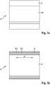
- the one in the Fig. 1 The device shown comprises a support profile 2 and a sliding holder 3, which is inserted into the support profile 2 in sections.
- the sliding holder 3 has a plate-shaped section 5 which engages on the one hand in an upper guide 4 and on the other hand in a lower guide 11 of the support profile 2.
- the plate-shaped section 5 has a profile 6 on the rear (see also Figures 5a, 5b and 5c ).
- the profiling 6 is in engagement with a profiling 7 of the support profile 2, which is configured in opposite fashion, the sliding holder 3 is thus held in the guide 4 of the support profile 2 in a form-fitting manner.
- a frictional connection is achieved between a terminal strip 9 inserted into the guide 4 and the sliding holder 3, so that the sliding holder 3 is fixed in position.
- the terminal strip 9 fills a guide play remaining between the sliding holder 3 and a profile section 10 of the supporting profile 2 that delimits the guide 4, so that the form fit between the sliding holder 3 and the supporting profile 2 is secured.
- the terminal strip 9 is also connected to the support profile 2 in a non-positive and form-fitting manner via a tongue 18 which engages in a groove 19 of the profile section 10 of the support profile 2.
- the terminal strip 9 has an essentially U-shaped cross section, so that the terminal strip 9 engages around the profile section 10 of the support profile 2 that delimits the guide 4.
- a flange 21 is formed at each end, which causes a stiffening of the terminal strip 9 (see Figures 6a and 6b ).
- the support profile 2 is in the Figures 4a and 4b presented in isolation.
- the cross section of the Figure 4a clearly shows that the guide 11 is designed differently from the guide 4.
- the guide 11 lacks a "rear wall”. Instead, a support wall 22 is provided, which is located in front of the actual guide 11.
- the sliding element 3 is first inserted into the guide 11 and pivoted around the support wall 22 in the support profile 2, so that then the sliding element 3 upwards into the Guide 4 can be inserted.
- the height of the sliding element 3 can be varied as desired, since the profile 6 can be brought into engagement with the profile 7 of the support profile 2 at any height.
- the sliding holder 3 After the height position has been determined by moving the sliding holder 3 in a first direction y, the sliding holder 3 can be moved horizontally with respect to the support profile 2, that is, in a second direction x (see FIG Fig. 3 ) to make the required adjustment.
- the terminal strip 9 is then inserted into the guide 4 or pushed in laterally.
- the slide holder 3 has a separate holding part 13 which is screwed into a threaded hole 15 of the slide holder 3.
- the longitudinal axis A of the threaded hole 15 defines a third direction z, which extends perpendicular to the plane of an on-site subsurface (not shown).
- the device of the Fig. 1 therefore allows adjustment in all three spatial directions, i.e. in the directions x, y and z.
- the slide holder 3 has to be moved in whole or in part.
- the support profile 2 remains unchanged after its assembly.
- a possibly existing substructure (not shown), via which the support profile 2 of the device is indirectly attached to the subsurface provided by the customer.
- the holding part 13 of the in the Fig. 1 The slide holder 3 shown has a recess 16 into which a mandrel 17 can be inserted.
- the mandrel 17 can be brought into engagement with a recess 23 of a plate-shaped facade element 1, as exemplified in FIG Fig. 10 shown.
- the mandrel 17 is held centrally in the recess 16 of the holding part 13, so that it can be brought into engagement with a further recess 16 of a further facade element 1.
- the holding part 13 therefore comes to rest in particular in a joint between two facade elements 1.
- FIG. 2 Another (second) preferred embodiment of a device according to the invention is that Fig. 2 refer to.
- the support profile 2 and the terminal strip 9 are designed in the same way as the support profile 2 and the terminal strip 9 of the embodiment described above.
- Only the slide holder 3 is modified.
- the sliding holder 3 is made in one piece and has no holding part 13.
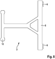
- the sliding holder 3 forms a holding section 12 which is T-shaped in cross section (see FIG Fig. 8 ) and can be brought into engagement with grooves 14 arranged at the end of two plate-shaped facade elements 1, as exemplified in FIG Fig. 11 shown.
- the slide holder 3 also has a plate-shaped section 5, which is designed analogously to the plate-shaped section 5 of the slide holder 3 of the embodiment described above, so that the slide holder 3 can be "swiveled” into the support profile 2 and positioned in an analogous manner (see FIG Fig. 9 ).
- the plate-shaped section 5 of the sliding holder 3 has a profiling 6 on the rear side, which can be brought into engagement with a profiling 7 of the support profile 2 which is configured in opposite directions (see FIG Figures 7a and 7b ).
- the rear profile 6 of the plate-shaped section 5 of the sliding holder 3 of a device according to the invention has several webs 6.1 and grooves 6.2 running parallel to the first direction x (see FIG Figure 5b and Figure 7b ). This means that even when the profiling 6 is in engagement with the profiling 7 of the support profile 2, a displacement of the sliding holder 3 in the direction x is possible. The position of the sliding holder 3 in the x direction is only achieved when the terminal strip 9 is inserted or pushed in.
- Fig. 5d forms the rear profiling 6 of the plate-shaped section 5 of the slide holder 3 of a device according to the invention in cross section teeth 8 which have tooth flanks 8.1, 8.2 which are inclined to different degrees.
- the tooth flank 8.1 is essentially perpendicular led to the plate-shaped section 5 of the slide holder 3, while the tooth flank 8.2 slopes down towards the base.
- the essentially vertically guided tooth flank 8.1 optimizes the form fit with the oppositely designed profiling 7 of the support profile 2, since the teeth 8 are optimally supported against one another.
- the inclined tooth flank 8.2 widens the base of the tooth 8 and thus leads to increased mechanical stability.
- particularly heavy panel-shaped facade elements 1 such as panels made of ceramic, natural stone or artificial stone, can be attached to an on-site substrate or to a substructure.
- Fig. 12 refers to.
- the support profile 2, the sliding holder 3 and the terminal strip 9 are identical to the embodiment of Fig. 1 executed. In this respect, the description for Fig. 1 to get expelled.
- the device of the Fig. 12 furthermore comprises a holding part 13 which is screwed into a threaded bore 15 of the slide holder 3.
- the longitudinal axis A of the threaded hole 15 also defines a third direction z here, which extends perpendicular to the plane of a subsurface (not shown) on site.
- Analogous to the device of Fig. 1 therefore also enables the device of Fig. 12 an adjustment in all three spatial directions, i.e. in the directions x, y and z.
- the slide holder 3 is moved for adjustment in the spatial directions x and y.
- the screw-in depth of the holding part 13 in the threaded hole 15 is changed.
- the holding part 13 shown has two receiving sections 24 which are each U-shaped so that they each encompass a facade element 1 of a corresponding width at the edge. In this way, a form fit is brought about, which holds the facade elements 1 securely.
- a leg 25, which protrudes from the respective facade element 1, can be used to design the facade (see FIG Fig. 13 ).
Landscapes
- Engineering & Computer Science (AREA)
- Architecture (AREA)
- Civil Engineering (AREA)
- Structural Engineering (AREA)
- Physics & Mathematics (AREA)
- Electromagnetism (AREA)
- Finishing Walls (AREA)
Claims (13)
- Dispositif, destiné à monter des éléments de façade en forme de panneaux (1) sur un support inhérent à un bâtiment ou sur une substructure fixée sur un support inhérent à un bâtiment, comprenant un profilé porteur (2) et un support à glissière (3), le support à glissière (3) comportant un segment (5) en forme de panneau, insérable dans un guidage (4) du profilé porteur (2), de sorte que le support à glissière (3) soit translatable par rapport au profilé porteur (2) dans une première direction (x), et le segment (5) en forme de panneau du support à glissière (3) comportant sur la face arrière un profilage (6), constitué de plusieurs listels (6.1) et/ou rainures (6.2) s'écoulant à la parallèle de la première direction (x) et étant susceptible d'être amené en engagement avec un profilage (7) conçu en étant diamétralement opposé du profilé porteur (2), de sorte que le support à glissière (3) soit susceptible d'être amené dans une deuxième direction (y) s'écoulant à la perpendiculaire de la première direction (x),
caractérisé en ce que la première direction x s'écoule à l'horizontale, la deuxième direction y s'écoule à la verticale et une troisième direction z s'écoule à la perpendiculaire du support inhérent au bâtiment et en ce que le dispositif comprend une baguette de serrage (9), qui est insérable au moins par segments dans le guidage (4) du profilé porteur (2), de sorte que le support à glissière (3) soit maintenu par complémentarité de force et de forme dans le guidage (4) . - Dispositif selon la revendication 1,
caractérisé en ce que le profilage (6, 7) du support à glissière (3) et/ou du profilé porteur (2) forme en section transversale une multiplicité de dents (8), qui sont façonnées de préférence de forme asymétrique, qui comportent notamment des flancs de dents (8.1, 8.2) plus ou moins inclinés. - Dispositif selon l'une quelconque des revendications précédentes,
caractérisé en ce que la baguette de serrage (9) est susceptible d'être assemblée par complémentarité de force et/ou de forme avec le profilé porteur (2), de préférence avec un segment de profilé (10) délimitant le guidage (4) du profilé porteur (2). - Dispositif selon l'une quelconque des revendications précédentes,
caractérisé en ce que, dans la section transversale, la baguette de serrage (9) est sensiblement conçue en forme de U, de telle sorte qu'après l'insertion, notamment l'emboîtement dans le guidage (4) du profilé porteur (2), la baguette de serrage (9) entoure le segment de profilé (10) du profilé porteur (2) délimitant le guidage (4). - Dispositif selon l'une quelconque des revendications précédentes,
caractérisé en ce que le profilé porteur (2) forme un guidage (11) supplémentaire pour le support à glissière (3) s'écoulant à la parallèle du guidage (4), de sorte que lorsque le support à glissière (3) est inséré, le profilé porteur (2) entoure sur deux côtés opposés le segment (5) du support à glissière (3) . - Dispositif selon l'une quelconque des revendications précédentes,
caractérisé en ce que le support à glissière (3) forme un segment de maintien (12) destiné à maintenir l'élément de façade en forme de panneau (1) ou comporte une pièce de maintien (13). - Dispositif selon la revendication 6,
caractérisé en ce que dans la section transversale, le segment de maintien (12) du support à glissière (3) est conçu en forme de T et est susceptible d'être amené en engagement avec des rainures (14) frontales de l'élément de façade en forme de panneau (1). - Dispositif selon la revendication 6,
caractérisé en ce que la pièce de maintien (13) est une pièce séparée, qui est vissée dans un taraudage (15) du support à glissière (3), l'axe longitudinal (A) du taraudage (15) s'étendant dans une troisième direction (z) s'écoulant à la perpendiculaire de la première direction (x) et à la perpendiculaire de la deuxième direction (y). - Dispositif selon la revendication 6 ou 8,
caractérisé en ce que la pièce de maintien (13) comporte un évidement (16) dans lequel un mandrin (17) est inséré, de préférence vissé ou emmanché. - Dispositif selon la revendication 6 ou 8,
caractérisé en ce que la pièce de maintien (13) comporte au moins un segment de réception (24), destiné à réceptionner un élément de façade (1), de préférence le segment de réception (24) étant conçu en forme de L ou de U et/ou entourant sur le bord l'élément de façade (1). - Dispositif selon l'une quelconque des revendications précédentes,
caractérisé en ce qu'en section transversale, le support à glissière (3) est réalisé en symétrie spéculaire et en ce que le segment en forme de panneau (5) comporte sur la face arrière, sur deux côtés mutuellement opposés un profilage (6), de sorte que l'orientation du support à glissière (3) soit invisible, lors de l'insertion dans le profilé porteur (2) . - Façade, dotée d'éléments de façade en forme de panneaux (1) rétro-aérés suspendus, qui sont montés à l'aide d'un dispositif selon l'une quelconque des revendications précédentes sur un support inhérent à un bâtiment ou sur une substructure fixée sur un support inhérent à un bâtiment.
- Façade selon la revendication 12,
caractérisée en ce que le profilé porteur (2) est orienté de telle manière que la première direction (x) s'écoule à l'horizontale, la deuxième direction (y) s'écoule à la verticale et la troisième direction (z) s'écoule à la perpendiculaire du plan du support inhérent au bâtiment.
Priority Applications (1)
| Application Number | Priority Date | Filing Date | Title |
|---|---|---|---|
| EP19187463.5A EP3767053B1 (fr) | 2019-07-19 | 2019-07-19 | Dispositif de montage des éléments de façade en forme de plaque sur un support côté bâtiment ou sur une substructure fixée sur un support côté bâtiment, façade pourvue d'éléments de façade en forme de plaque |
Applications Claiming Priority (1)
| Application Number | Priority Date | Filing Date | Title |
|---|---|---|---|
| EP19187463.5A EP3767053B1 (fr) | 2019-07-19 | 2019-07-19 | Dispositif de montage des éléments de façade en forme de plaque sur un support côté bâtiment ou sur une substructure fixée sur un support côté bâtiment, façade pourvue d'éléments de façade en forme de plaque |
Publications (2)
| Publication Number | Publication Date |
|---|---|
| EP3767053A1 EP3767053A1 (fr) | 2021-01-20 |
| EP3767053B1 true EP3767053B1 (fr) | 2021-07-07 |
Family
ID=67438313
Family Applications (1)
| Application Number | Title | Priority Date | Filing Date |
|---|---|---|---|
| EP19187463.5A Active EP3767053B1 (fr) | 2019-07-19 | 2019-07-19 | Dispositif de montage des éléments de façade en forme de plaque sur un support côté bâtiment ou sur une substructure fixée sur un support côté bâtiment, façade pourvue d'éléments de façade en forme de plaque |
Country Status (1)
| Country | Link |
|---|---|
| EP (1) | EP3767053B1 (fr) |
Family Cites Families (3)
| Publication number | Priority date | Publication date | Assignee | Title |
|---|---|---|---|---|
| EP0045978B1 (fr) * | 1980-08-13 | 1984-01-18 | Walter Dipl.-Ing. Haase | Barre de support à ancrer dans la construction de support pour une façade consistant en plaques de pierre de taille, de béton ou de céramique |
| DE3643903A1 (de) * | 1986-12-22 | 1988-07-07 | Hermann Dipl Ing Loos | Unterkonstruktion fuer fassadenbekleidungen |
| CH679874A5 (fr) | 1989-11-16 | 1992-04-30 | Ickler Sa |
-
2019
- 2019-07-19 EP EP19187463.5A patent/EP3767053B1/fr active Active
Also Published As
| Publication number | Publication date |
|---|---|
| EP3767053A1 (fr) | 2021-01-20 |
Similar Documents
| Publication | Publication Date | Title |
|---|---|---|
| EP0945577B2 (fr) | Utilisation d'une barre profilée pour soutenir des encadrements pour portes ou fenêtres | |
| EP2063047B1 (fr) | Système de rails profilés | |
| EP3199738B1 (fr) | Système de retenue de rambarde en verre et partie de renfort destinée à être utilisée dans un tel système | |
| DE102018126983B4 (de) | System zur Befestigung von Verkleidungselementen an Bauwerken, Bauwerk mit entsprechend befestigten Verkleidungselementen sowie Verfahren zur Montage und Demontage von Verkleidungselementen | |
| DE202014100163U1 (de) | Klemmteil zur Fixierung von Geländerplatten in Halteprofilen | |
| EP2159345B1 (fr) | Fixation pour éléments de revêtement | |
| DE2610998B2 (de) | Halterung zur Befestigung von Bekleidungsplatten vor einer Bauwerkswand | |
| EP3767053B1 (fr) | Dispositif de montage des éléments de façade en forme de plaque sur un support côté bâtiment ou sur une substructure fixée sur un support côté bâtiment, façade pourvue d'éléments de façade en forme de plaque | |
| EP3594427B1 (fr) | Système et procédé de fixation d'éléments de façade | |
| EP2647779B1 (fr) | Support d'angle pour une infrastructure de façade | |
| EP2423622A2 (fr) | Dispositif de fixation d'un rail de support | |
| EP1873340B1 (fr) | Installation de porte | |
| EP3245345A1 (fr) | Construction à montants et traverses | |
| EP2447441B1 (fr) | Dispositif de fixation pour des éléments de bardage | |
| DE4016164A1 (de) | Befestigungskonsole fuer ein fassadenbefestigungssystem | |
| DE19804925B4 (de) | Haltevorrichtung für Füllelemente in einer Wandkonstruktion | |
| DE102006060455B4 (de) | Befestigungssystem zur Rand- und/oder Eckbefestigung von wenigstens einem Paneel | |
| DE4029967A1 (de) | Mehrzweckprofilschiene, insbesondere fuer glaser | |
| DE102014104542A1 (de) | Befestigungsvorrichtung für Trockenbauwände | |
| EP4108849B1 (fr) | Système de profilé destiné à la formation d'une sous-construction de plancher de terrasse | |
| DE202005017781U1 (de) | Verbindungsvorrichtung zum Verbinden von Baukörpern | |
| EP3712367B1 (fr) | Collier de serrage d'intrados | |
| EP3772558B1 (fr) | Profilé de retenue destiné au montage d'un élément de surface et compensation des tolérances | |
| DE102008013263A1 (de) | Befestigungssystem für ein plattenförmiges Bauelement auf einem Schrägdach | |
| DE202004010160U1 (de) | Universalprofil |
Legal Events
| Date | Code | Title | Description |
|---|---|---|---|
| PUAI | Public reference made under article 153(3) epc to a published international application that has entered the european phase |
Free format text: ORIGINAL CODE: 0009012 |
|
| STAA | Information on the status of an ep patent application or granted ep patent |
Free format text: STATUS: EXAMINATION IS IN PROGRESS |
|
| 17P | Request for examination filed |
Effective date: 20200312 |
|
| AK | Designated contracting states |
Kind code of ref document: A1 Designated state(s): AL AT BE BG CH CY CZ DE DK EE ES FI FR GB GR HR HU IE IS IT LI LT LU LV MC MK MT NL NO PL PT RO RS SE SI SK SM TR |
|
| AX | Request for extension of the european patent |
Extension state: BA ME |
|
| STAA | Information on the status of an ep patent application or granted ep patent |
Free format text: STATUS: EXAMINATION IS IN PROGRESS |
|
| GRAP | Despatch of communication of intention to grant a patent |
Free format text: ORIGINAL CODE: EPIDOSNIGR1 |
|
| STAA | Information on the status of an ep patent application or granted ep patent |
Free format text: STATUS: GRANT OF PATENT IS INTENDED |
|
| INTG | Intention to grant announced |
Effective date: 20210215 |
|
| GRAS | Grant fee paid |
Free format text: ORIGINAL CODE: EPIDOSNIGR3 |
|
| GRAA | (expected) grant |
Free format text: ORIGINAL CODE: 0009210 |
|
| STAA | Information on the status of an ep patent application or granted ep patent |
Free format text: STATUS: THE PATENT HAS BEEN GRANTED |
|
| AK | Designated contracting states |
Kind code of ref document: B1 Designated state(s): AL AT BE BG CH CY CZ DE DK EE ES FI FR GB GR HR HU IE IS IT LI LT LU LV MC MK MT NL NO PL PT RO RS SE SI SK SM TR |
|
| REG | Reference to a national code |
Ref country code: GB Ref legal event code: FG4D Free format text: NOT ENGLISH |
|
| REG | Reference to a national code |
Ref country code: AT Ref legal event code: REF Ref document number: 1408735 Country of ref document: AT Kind code of ref document: T Effective date: 20210715 |
|
| REG | Reference to a national code |
Ref country code: DE Ref legal event code: R096 Ref document number: 502019001767 Country of ref document: DE |
|
| REG | Reference to a national code |
Ref country code: IE Ref legal event code: FG4D Free format text: LANGUAGE OF EP DOCUMENT: GERMAN |
|
| REG | Reference to a national code |
Ref country code: LT Ref legal event code: MG9D |
|
| REG | Reference to a national code |
Ref country code: NL Ref legal event code: MP Effective date: 20210707 |
|
| PG25 | Lapsed in a contracting state [announced via postgrant information from national office to epo] |
Ref country code: BG Free format text: LAPSE BECAUSE OF FAILURE TO SUBMIT A TRANSLATION OF THE DESCRIPTION OR TO PAY THE FEE WITHIN THE PRESCRIBED TIME-LIMIT Effective date: 20211007 Ref country code: LT Free format text: LAPSE BECAUSE OF FAILURE TO SUBMIT A TRANSLATION OF THE DESCRIPTION OR TO PAY THE FEE WITHIN THE PRESCRIBED TIME-LIMIT Effective date: 20210707 Ref country code: NL Free format text: LAPSE BECAUSE OF FAILURE TO SUBMIT A TRANSLATION OF THE DESCRIPTION OR TO PAY THE FEE WITHIN THE PRESCRIBED TIME-LIMIT Effective date: 20210707 Ref country code: NO Free format text: LAPSE BECAUSE OF FAILURE TO SUBMIT A TRANSLATION OF THE DESCRIPTION OR TO PAY THE FEE WITHIN THE PRESCRIBED TIME-LIMIT Effective date: 20211007 Ref country code: PT Free format text: LAPSE BECAUSE OF FAILURE TO SUBMIT A TRANSLATION OF THE DESCRIPTION OR TO PAY THE FEE WITHIN THE PRESCRIBED TIME-LIMIT Effective date: 20211108 Ref country code: HR Free format text: LAPSE BECAUSE OF FAILURE TO SUBMIT A TRANSLATION OF THE DESCRIPTION OR TO PAY THE FEE WITHIN THE PRESCRIBED TIME-LIMIT Effective date: 20210707 Ref country code: RS Free format text: LAPSE BECAUSE OF FAILURE TO SUBMIT A TRANSLATION OF THE DESCRIPTION OR TO PAY THE FEE WITHIN THE PRESCRIBED TIME-LIMIT Effective date: 20210707 Ref country code: SE Free format text: LAPSE BECAUSE OF FAILURE TO SUBMIT A TRANSLATION OF THE DESCRIPTION OR TO PAY THE FEE WITHIN THE PRESCRIBED TIME-LIMIT Effective date: 20210707 Ref country code: FI Free format text: LAPSE BECAUSE OF FAILURE TO SUBMIT A TRANSLATION OF THE DESCRIPTION OR TO PAY THE FEE WITHIN THE PRESCRIBED TIME-LIMIT Effective date: 20210707 Ref country code: ES Free format text: LAPSE BECAUSE OF FAILURE TO SUBMIT A TRANSLATION OF THE DESCRIPTION OR TO PAY THE FEE WITHIN THE PRESCRIBED TIME-LIMIT Effective date: 20210707 |
|
| PG25 | Lapsed in a contracting state [announced via postgrant information from national office to epo] |
Ref country code: PL Free format text: LAPSE BECAUSE OF FAILURE TO SUBMIT A TRANSLATION OF THE DESCRIPTION OR TO PAY THE FEE WITHIN THE PRESCRIBED TIME-LIMIT Effective date: 20210707 Ref country code: LV Free format text: LAPSE BECAUSE OF FAILURE TO SUBMIT A TRANSLATION OF THE DESCRIPTION OR TO PAY THE FEE WITHIN THE PRESCRIBED TIME-LIMIT Effective date: 20210707 Ref country code: GR Free format text: LAPSE BECAUSE OF FAILURE TO SUBMIT A TRANSLATION OF THE DESCRIPTION OR TO PAY THE FEE WITHIN THE PRESCRIBED TIME-LIMIT Effective date: 20211008 |
|
| REG | Reference to a national code |
Ref country code: BE Ref legal event code: MM Effective date: 20210731 |
|
| REG | Reference to a national code |
Ref country code: DE Ref legal event code: R097 Ref document number: 502019001767 Country of ref document: DE |
|
| PG25 | Lapsed in a contracting state [announced via postgrant information from national office to epo] |
Ref country code: DK Free format text: LAPSE BECAUSE OF FAILURE TO SUBMIT A TRANSLATION OF THE DESCRIPTION OR TO PAY THE FEE WITHIN THE PRESCRIBED TIME-LIMIT Effective date: 20210707 |
|
| PLBE | No opposition filed within time limit |
Free format text: ORIGINAL CODE: 0009261 |
|
| STAA | Information on the status of an ep patent application or granted ep patent |
Free format text: STATUS: NO OPPOSITION FILED WITHIN TIME LIMIT |
|
| PG25 | Lapsed in a contracting state [announced via postgrant information from national office to epo] |
Ref country code: SM Free format text: LAPSE BECAUSE OF FAILURE TO SUBMIT A TRANSLATION OF THE DESCRIPTION OR TO PAY THE FEE WITHIN THE PRESCRIBED TIME-LIMIT Effective date: 20210707 Ref country code: SK Free format text: LAPSE BECAUSE OF FAILURE TO SUBMIT A TRANSLATION OF THE DESCRIPTION OR TO PAY THE FEE WITHIN THE PRESCRIBED TIME-LIMIT Effective date: 20210707 Ref country code: RO Free format text: LAPSE BECAUSE OF FAILURE TO SUBMIT A TRANSLATION OF THE DESCRIPTION OR TO PAY THE FEE WITHIN THE PRESCRIBED TIME-LIMIT Effective date: 20210707 Ref country code: MC Free format text: LAPSE BECAUSE OF FAILURE TO SUBMIT A TRANSLATION OF THE DESCRIPTION OR TO PAY THE FEE WITHIN THE PRESCRIBED TIME-LIMIT Effective date: 20210707 Ref country code: LU Free format text: LAPSE BECAUSE OF NON-PAYMENT OF DUE FEES Effective date: 20210719 Ref country code: EE Free format text: LAPSE BECAUSE OF FAILURE TO SUBMIT A TRANSLATION OF THE DESCRIPTION OR TO PAY THE FEE WITHIN THE PRESCRIBED TIME-LIMIT Effective date: 20210707 Ref country code: CZ Free format text: LAPSE BECAUSE OF FAILURE TO SUBMIT A TRANSLATION OF THE DESCRIPTION OR TO PAY THE FEE WITHIN THE PRESCRIBED TIME-LIMIT Effective date: 20210707 Ref country code: AL Free format text: LAPSE BECAUSE OF FAILURE TO SUBMIT A TRANSLATION OF THE DESCRIPTION OR TO PAY THE FEE WITHIN THE PRESCRIBED TIME-LIMIT Effective date: 20210707 |
|
| 26N | No opposition filed |
Effective date: 20220408 |
|
| PG25 | Lapsed in a contracting state [announced via postgrant information from national office to epo] |
Ref country code: IT Free format text: LAPSE BECAUSE OF FAILURE TO SUBMIT A TRANSLATION OF THE DESCRIPTION OR TO PAY THE FEE WITHIN THE PRESCRIBED TIME-LIMIT Effective date: 20210707 Ref country code: FR Free format text: LAPSE BECAUSE OF NON-PAYMENT OF DUE FEES Effective date: 20210907 Ref country code: BE Free format text: LAPSE BECAUSE OF NON-PAYMENT OF DUE FEES Effective date: 20210731 |
|
| REG | Reference to a national code |
Ref country code: CH Ref legal event code: PL |
|
| PG25 | Lapsed in a contracting state [announced via postgrant information from national office to epo] |
Ref country code: LI Free format text: LAPSE BECAUSE OF NON-PAYMENT OF DUE FEES Effective date: 20220731 Ref country code: CH Free format text: LAPSE BECAUSE OF NON-PAYMENT OF DUE FEES Effective date: 20220731 |
|
| PG25 | Lapsed in a contracting state [announced via postgrant information from national office to epo] |
Ref country code: CY Free format text: LAPSE BECAUSE OF FAILURE TO SUBMIT A TRANSLATION OF THE DESCRIPTION OR TO PAY THE FEE WITHIN THE PRESCRIBED TIME-LIMIT Effective date: 20210707 |
|
| PG25 | Lapsed in a contracting state [announced via postgrant information from national office to epo] |
Ref country code: HU Free format text: LAPSE BECAUSE OF FAILURE TO SUBMIT A TRANSLATION OF THE DESCRIPTION OR TO PAY THE FEE WITHIN THE PRESCRIBED TIME-LIMIT; INVALID AB INITIO Effective date: 20190719 |
|
| PGFP | Annual fee paid to national office [announced via postgrant information from national office to epo] |
Ref country code: IE Payment date: 20230719 Year of fee payment: 5 Ref country code: GB Payment date: 20230721 Year of fee payment: 5 |
|
| PGFP | Annual fee paid to national office [announced via postgrant information from national office to epo] |
Ref country code: DE Payment date: 20230719 Year of fee payment: 5 |
|
| PG25 | Lapsed in a contracting state [announced via postgrant information from national office to epo] |
Ref country code: MK Free format text: LAPSE BECAUSE OF FAILURE TO SUBMIT A TRANSLATION OF THE DESCRIPTION OR TO PAY THE FEE WITHIN THE PRESCRIBED TIME-LIMIT Effective date: 20210707 |