EP3765384B1 - Ventilanordnung und abgabgevorrichtung - Google Patents
Ventilanordnung und abgabgevorrichtung Download PDFInfo
- Publication number
- EP3765384B1 EP3765384B1 EP19706386.0A EP19706386A EP3765384B1 EP 3765384 B1 EP3765384 B1 EP 3765384B1 EP 19706386 A EP19706386 A EP 19706386A EP 3765384 B1 EP3765384 B1 EP 3765384B1
- Authority
- EP
- European Patent Office
- Prior art keywords
- valve
- valve plate
- fastening part
- container
- fixing part
- Prior art date
- Legal status (The legal status is an assumption and is not a legal conclusion. Google has not performed a legal analysis and makes no representation as to the accuracy of the status listed.)
- Active
Links
Images






Classifications
-
- B—PERFORMING OPERATIONS; TRANSPORTING
- B23—MACHINE TOOLS; METAL-WORKING NOT OTHERWISE PROVIDED FOR
- B23K—SOLDERING OR UNSOLDERING; WELDING; CLADDING OR PLATING BY SOLDERING OR WELDING; CUTTING BY APPLYING HEAT LOCALLY, e.g. FLAME CUTTING; WORKING BY LASER BEAM
- B23K20/00—Non-electric welding by applying impact or other pressure, with or without the application of heat, e.g. cladding or plating
- B23K20/10—Non-electric welding by applying impact or other pressure, with or without the application of heat, e.g. cladding or plating making use of vibrations, e.g. ultrasonic welding
-
- B—PERFORMING OPERATIONS; TRANSPORTING
- B23—MACHINE TOOLS; METAL-WORKING NOT OTHERWISE PROVIDED FOR
- B23K—SOLDERING OR UNSOLDERING; WELDING; CLADDING OR PLATING BY SOLDERING OR WELDING; CUTTING BY APPLYING HEAT LOCALLY, e.g. FLAME CUTTING; WORKING BY LASER BEAM
- B23K20/00—Non-electric welding by applying impact or other pressure, with or without the application of heat, e.g. cladding or plating
- B23K20/12—Non-electric welding by applying impact or other pressure, with or without the application of heat, e.g. cladding or plating the heat being generated by friction; Friction welding
-
- B—PERFORMING OPERATIONS; TRANSPORTING
- B29—WORKING OF PLASTICS; WORKING OF SUBSTANCES IN A PLASTIC STATE IN GENERAL
- B29C—SHAPING OR JOINING OF PLASTICS; SHAPING OF MATERIAL IN A PLASTIC STATE, NOT OTHERWISE PROVIDED FOR; AFTER-TREATMENT OF THE SHAPED PRODUCTS, e.g. REPAIRING
- B29C65/00—Joining or sealing of preformed parts, e.g. welding of plastics materials; Apparatus therefor
- B29C65/02—Joining or sealing of preformed parts, e.g. welding of plastics materials; Apparatus therefor by heating, with or without pressure
- B29C65/06—Joining or sealing of preformed parts, e.g. welding of plastics materials; Apparatus therefor by heating, with or without pressure using friction, e.g. spin welding
-
- B—PERFORMING OPERATIONS; TRANSPORTING
- B29—WORKING OF PLASTICS; WORKING OF SUBSTANCES IN A PLASTIC STATE IN GENERAL
- B29C—SHAPING OR JOINING OF PLASTICS; SHAPING OF MATERIAL IN A PLASTIC STATE, NOT OTHERWISE PROVIDED FOR; AFTER-TREATMENT OF THE SHAPED PRODUCTS, e.g. REPAIRING
- B29C65/00—Joining or sealing of preformed parts, e.g. welding of plastics materials; Apparatus therefor
- B29C65/02—Joining or sealing of preformed parts, e.g. welding of plastics materials; Apparatus therefor by heating, with or without pressure
- B29C65/06—Joining or sealing of preformed parts, e.g. welding of plastics materials; Apparatus therefor by heating, with or without pressure using friction, e.g. spin welding
- B29C65/0672—Spin welding
-
- B—PERFORMING OPERATIONS; TRANSPORTING
- B29—WORKING OF PLASTICS; WORKING OF SUBSTANCES IN A PLASTIC STATE IN GENERAL
- B29C—SHAPING OR JOINING OF PLASTICS; SHAPING OF MATERIAL IN A PLASTIC STATE, NOT OTHERWISE PROVIDED FOR; AFTER-TREATMENT OF THE SHAPED PRODUCTS, e.g. REPAIRING
- B29C65/00—Joining or sealing of preformed parts, e.g. welding of plastics materials; Apparatus therefor
- B29C65/02—Joining or sealing of preformed parts, e.g. welding of plastics materials; Apparatus therefor by heating, with or without pressure
- B29C65/06—Joining or sealing of preformed parts, e.g. welding of plastics materials; Apparatus therefor by heating, with or without pressure using friction, e.g. spin welding
- B29C65/069—Joining or sealing of preformed parts, e.g. welding of plastics materials; Apparatus therefor by heating, with or without pressure using friction, e.g. spin welding the welding tool cooperating with specially formed features of at least one of the parts to be joined, e.g. cooperating with holes or ribs of at least one of the parts to be joined
-
- B—PERFORMING OPERATIONS; TRANSPORTING
- B29—WORKING OF PLASTICS; WORKING OF SUBSTANCES IN A PLASTIC STATE IN GENERAL
- B29C—SHAPING OR JOINING OF PLASTICS; SHAPING OF MATERIAL IN A PLASTIC STATE, NOT OTHERWISE PROVIDED FOR; AFTER-TREATMENT OF THE SHAPED PRODUCTS, e.g. REPAIRING
- B29C65/00—Joining or sealing of preformed parts, e.g. welding of plastics materials; Apparatus therefor
- B29C65/02—Joining or sealing of preformed parts, e.g. welding of plastics materials; Apparatus therefor by heating, with or without pressure
- B29C65/08—Joining or sealing of preformed parts, e.g. welding of plastics materials; Apparatus therefor by heating, with or without pressure using ultrasonic vibrations
-
- B—PERFORMING OPERATIONS; TRANSPORTING
- B29—WORKING OF PLASTICS; WORKING OF SUBSTANCES IN A PLASTIC STATE IN GENERAL
- B29C—SHAPING OR JOINING OF PLASTICS; SHAPING OF MATERIAL IN A PLASTIC STATE, NOT OTHERWISE PROVIDED FOR; AFTER-TREATMENT OF THE SHAPED PRODUCTS, e.g. REPAIRING
- B29C66/00—General aspects of processes or apparatus for joining preformed parts
- B29C66/01—General aspects dealing with the joint area or with the area to be joined
- B29C66/05—Particular design of joint configurations
- B29C66/10—Particular design of joint configurations particular design of the joint cross-sections
- B29C66/11—Joint cross-sections comprising a single joint-segment, i.e. one of the parts to be joined comprising a single joint-segment in the joint cross-section
- B29C66/112—Single lapped joints
-
- B—PERFORMING OPERATIONS; TRANSPORTING
- B29—WORKING OF PLASTICS; WORKING OF SUBSTANCES IN A PLASTIC STATE IN GENERAL
- B29C—SHAPING OR JOINING OF PLASTICS; SHAPING OF MATERIAL IN A PLASTIC STATE, NOT OTHERWISE PROVIDED FOR; AFTER-TREATMENT OF THE SHAPED PRODUCTS, e.g. REPAIRING
- B29C66/00—General aspects of processes or apparatus for joining preformed parts
- B29C66/01—General aspects dealing with the joint area or with the area to be joined
- B29C66/05—Particular design of joint configurations
- B29C66/10—Particular design of joint configurations particular design of the joint cross-sections
- B29C66/11—Joint cross-sections comprising a single joint-segment, i.e. one of the parts to be joined comprising a single joint-segment in the joint cross-section
- B29C66/114—Single butt joints
-
- B—PERFORMING OPERATIONS; TRANSPORTING
- B29—WORKING OF PLASTICS; WORKING OF SUBSTANCES IN A PLASTIC STATE IN GENERAL
- B29C—SHAPING OR JOINING OF PLASTICS; SHAPING OF MATERIAL IN A PLASTIC STATE, NOT OTHERWISE PROVIDED FOR; AFTER-TREATMENT OF THE SHAPED PRODUCTS, e.g. REPAIRING
- B29C66/00—General aspects of processes or apparatus for joining preformed parts
- B29C66/50—General aspects of joining tubular articles; General aspects of joining long products, i.e. bars or profiled elements; General aspects of joining single elements to tubular articles, hollow articles or bars; General aspects of joining several hollow-preforms to form hollow or tubular articles
- B29C66/51—Joining tubular articles, profiled elements or bars; Joining single elements to tubular articles, hollow articles or bars; Joining several hollow-preforms to form hollow or tubular articles
- B29C66/53—Joining single elements to tubular articles, hollow articles or bars
- B29C66/534—Joining single elements to open ends of tubular or hollow articles or to the ends of bars
- B29C66/5344—Joining single elements to open ends of tubular or hollow articles or to the ends of bars said single elements being substantially annular, i.e. of finite length, e.g. joining flanges to tube ends
-
- B—PERFORMING OPERATIONS; TRANSPORTING
- B29—WORKING OF PLASTICS; WORKING OF SUBSTANCES IN A PLASTIC STATE IN GENERAL
- B29C—SHAPING OR JOINING OF PLASTICS; SHAPING OF MATERIAL IN A PLASTIC STATE, NOT OTHERWISE PROVIDED FOR; AFTER-TREATMENT OF THE SHAPED PRODUCTS, e.g. REPAIRING
- B29C66/00—General aspects of processes or apparatus for joining preformed parts
- B29C66/50—General aspects of joining tubular articles; General aspects of joining long products, i.e. bars or profiled elements; General aspects of joining single elements to tubular articles, hollow articles or bars; General aspects of joining several hollow-preforms to form hollow or tubular articles
- B29C66/51—Joining tubular articles, profiled elements or bars; Joining single elements to tubular articles, hollow articles or bars; Joining several hollow-preforms to form hollow or tubular articles
- B29C66/54—Joining several hollow-preforms, e.g. half-shells, to form hollow articles, e.g. for making balls, containers; Joining several hollow-preforms, e.g. half-cylinders, to form tubular articles
- B29C66/542—Joining several hollow-preforms, e.g. half-shells, to form hollow articles, e.g. for making balls, containers; Joining several hollow-preforms, e.g. half-cylinders, to form tubular articles joining hollow covers or hollow bottoms to open ends of container bodies
-
- B—PERFORMING OPERATIONS; TRANSPORTING
- B29—WORKING OF PLASTICS; WORKING OF SUBSTANCES IN A PLASTIC STATE IN GENERAL
- B29C—SHAPING OR JOINING OF PLASTICS; SHAPING OF MATERIAL IN A PLASTIC STATE, NOT OTHERWISE PROVIDED FOR; AFTER-TREATMENT OF THE SHAPED PRODUCTS, e.g. REPAIRING
- B29C66/00—General aspects of processes or apparatus for joining preformed parts
- B29C66/70—General aspects of processes or apparatus for joining preformed parts characterised by the composition, physical properties or the structure of the material of the parts to be joined; Joining with non-plastics material
- B29C66/73—General aspects of processes or apparatus for joining preformed parts characterised by the composition, physical properties or the structure of the material of the parts to be joined; Joining with non-plastics material characterised by the intensive physical properties of the material of the parts to be joined, by the optical properties of the material of the parts to be joined, by the extensive physical properties of the parts to be joined, by the state of the material of the parts to be joined or by the material of the parts to be joined being a thermoplastic or a thermoset
- B29C66/739—General aspects of processes or apparatus for joining preformed parts characterised by the composition, physical properties or the structure of the material of the parts to be joined; Joining with non-plastics material characterised by the intensive physical properties of the material of the parts to be joined, by the optical properties of the material of the parts to be joined, by the extensive physical properties of the parts to be joined, by the state of the material of the parts to be joined or by the material of the parts to be joined being a thermoplastic or a thermoset characterised by the material of the parts to be joined being a thermoplastic or a thermoset
- B29C66/7392—General aspects of processes or apparatus for joining preformed parts characterised by the composition, physical properties or the structure of the material of the parts to be joined; Joining with non-plastics material characterised by the intensive physical properties of the material of the parts to be joined, by the optical properties of the material of the parts to be joined, by the extensive physical properties of the parts to be joined, by the state of the material of the parts to be joined or by the material of the parts to be joined being a thermoplastic or a thermoset characterised by the material of the parts to be joined being a thermoplastic or a thermoset characterised by the material of at least one of the parts being a thermoplastic
-
- B—PERFORMING OPERATIONS; TRANSPORTING
- B29—WORKING OF PLASTICS; WORKING OF SUBSTANCES IN A PLASTIC STATE IN GENERAL
- B29C—SHAPING OR JOINING OF PLASTICS; SHAPING OF MATERIAL IN A PLASTIC STATE, NOT OTHERWISE PROVIDED FOR; AFTER-TREATMENT OF THE SHAPED PRODUCTS, e.g. REPAIRING
- B29C66/00—General aspects of processes or apparatus for joining preformed parts
- B29C66/70—General aspects of processes or apparatus for joining preformed parts characterised by the composition, physical properties or the structure of the material of the parts to be joined; Joining with non-plastics material
- B29C66/74—Joining plastics material to non-plastics material
- B29C66/742—Joining plastics material to non-plastics material to metals or their alloys
-
- B—PERFORMING OPERATIONS; TRANSPORTING
- B65—CONVEYING; PACKING; STORING; HANDLING THIN OR FILAMENTARY MATERIAL
- B65D—CONTAINERS FOR STORAGE OR TRANSPORT OF ARTICLES OR MATERIALS, e.g. BAGS, BARRELS, BOTTLES, BOXES, CANS, CARTONS, CRATES, DRUMS, JARS, TANKS, HOPPERS, FORWARDING CONTAINERS; ACCESSORIES, CLOSURES, OR FITTINGS THEREFOR; PACKAGING ELEMENTS; PACKAGES
- B65D83/00—Containers or packages with special means for dispensing contents
- B65D83/14—Containers for dispensing liquid or semi-liquid contents by internal gaseous pressure, i.e. aerosol containers comprising propellant
- B65D83/44—Valves specially adapted for the discharge of contents; Regulating devices
- B65D83/48—Lift valves, e.g. operated by push action
-
- B—PERFORMING OPERATIONS; TRANSPORTING
- B29—WORKING OF PLASTICS; WORKING OF SUBSTANCES IN A PLASTIC STATE IN GENERAL
- B29C—SHAPING OR JOINING OF PLASTICS; SHAPING OF MATERIAL IN A PLASTIC STATE, NOT OTHERWISE PROVIDED FOR; AFTER-TREATMENT OF THE SHAPED PRODUCTS, e.g. REPAIRING
- B29C65/00—Joining or sealing of preformed parts, e.g. welding of plastics materials; Apparatus therefor
- B29C65/02—Joining or sealing of preformed parts, e.g. welding of plastics materials; Apparatus therefor by heating, with or without pressure
- B29C65/14—Joining or sealing of preformed parts, e.g. welding of plastics materials; Apparatus therefor by heating, with or without pressure using wave energy, i.e. electromagnetic radiation, or particle radiation
- B29C65/16—Laser beams
- B29C65/1629—Laser beams characterised by the way of heating the interface
- B29C65/1635—Laser beams characterised by the way of heating the interface at least passing through one of the parts to be joined, i.e. laser transmission welding
-
- B—PERFORMING OPERATIONS; TRANSPORTING
- B29—WORKING OF PLASTICS; WORKING OF SUBSTANCES IN A PLASTIC STATE IN GENERAL
- B29C—SHAPING OR JOINING OF PLASTICS; SHAPING OF MATERIAL IN A PLASTIC STATE, NOT OTHERWISE PROVIDED FOR; AFTER-TREATMENT OF THE SHAPED PRODUCTS, e.g. REPAIRING
- B29C66/00—General aspects of processes or apparatus for joining preformed parts
- B29C66/70—General aspects of processes or apparatus for joining preformed parts characterised by the composition, physical properties or the structure of the material of the parts to be joined; Joining with non-plastics material
- B29C66/71—General aspects of processes or apparatus for joining preformed parts characterised by the composition, physical properties or the structure of the material of the parts to be joined; Joining with non-plastics material characterised by the composition of the plastics material of the parts to be joined
-
- B—PERFORMING OPERATIONS; TRANSPORTING
- B29—WORKING OF PLASTICS; WORKING OF SUBSTANCES IN A PLASTIC STATE IN GENERAL
- B29C—SHAPING OR JOINING OF PLASTICS; SHAPING OF MATERIAL IN A PLASTIC STATE, NOT OTHERWISE PROVIDED FOR; AFTER-TREATMENT OF THE SHAPED PRODUCTS, e.g. REPAIRING
- B29C66/00—General aspects of processes or apparatus for joining preformed parts
- B29C66/70—General aspects of processes or apparatus for joining preformed parts characterised by the composition, physical properties or the structure of the material of the parts to be joined; Joining with non-plastics material
- B29C66/73—General aspects of processes or apparatus for joining preformed parts characterised by the composition, physical properties or the structure of the material of the parts to be joined; Joining with non-plastics material characterised by the intensive physical properties of the material of the parts to be joined, by the optical properties of the material of the parts to be joined, by the extensive physical properties of the parts to be joined, by the state of the material of the parts to be joined or by the material of the parts to be joined being a thermoplastic or a thermoset
- B29C66/739—General aspects of processes or apparatus for joining preformed parts characterised by the composition, physical properties or the structure of the material of the parts to be joined; Joining with non-plastics material characterised by the intensive physical properties of the material of the parts to be joined, by the optical properties of the material of the parts to be joined, by the extensive physical properties of the parts to be joined, by the state of the material of the parts to be joined or by the material of the parts to be joined being a thermoplastic or a thermoset characterised by the material of the parts to be joined being a thermoplastic or a thermoset
- B29C66/7392—General aspects of processes or apparatus for joining preformed parts characterised by the composition, physical properties or the structure of the material of the parts to be joined; Joining with non-plastics material characterised by the intensive physical properties of the material of the parts to be joined, by the optical properties of the material of the parts to be joined, by the extensive physical properties of the parts to be joined, by the state of the material of the parts to be joined or by the material of the parts to be joined being a thermoplastic or a thermoset characterised by the material of the parts to be joined being a thermoplastic or a thermoset characterised by the material of at least one of the parts being a thermoplastic
- B29C66/73921—General aspects of processes or apparatus for joining preformed parts characterised by the composition, physical properties or the structure of the material of the parts to be joined; Joining with non-plastics material characterised by the intensive physical properties of the material of the parts to be joined, by the optical properties of the material of the parts to be joined, by the extensive physical properties of the parts to be joined, by the state of the material of the parts to be joined or by the material of the parts to be joined being a thermoplastic or a thermoset characterised by the material of the parts to be joined being a thermoplastic or a thermoset characterised by the material of at least one of the parts being a thermoplastic characterised by the materials of both parts being thermoplastics
-
- B—PERFORMING OPERATIONS; TRANSPORTING
- B29—WORKING OF PLASTICS; WORKING OF SUBSTANCES IN A PLASTIC STATE IN GENERAL
- B29L—INDEXING SCHEME ASSOCIATED WITH SUBCLASS B29C, RELATING TO PARTICULAR ARTICLES
- B29L2031/00—Other particular articles
- B29L2031/712—Containers; Packaging elements or accessories, Packages
- B29L2031/7158—Bottles
-
- B—PERFORMING OPERATIONS; TRANSPORTING
- B29—WORKING OF PLASTICS; WORKING OF SUBSTANCES IN A PLASTIC STATE IN GENERAL
- B29L—INDEXING SCHEME ASSOCIATED WITH SUBCLASS B29C, RELATING TO PARTICULAR ARTICLES
- B29L2031/00—Other particular articles
- B29L2031/748—Machines or parts thereof not otherwise provided for
- B29L2031/7506—Valves
-
- B—PERFORMING OPERATIONS; TRANSPORTING
- B65—CONVEYING; PACKING; STORING; HANDLING THIN OR FILAMENTARY MATERIAL
- B65D—CONTAINERS FOR STORAGE OR TRANSPORT OF ARTICLES OR MATERIALS, e.g. BAGS, BARRELS, BOTTLES, BOXES, CANS, CARTONS, CRATES, DRUMS, JARS, TANKS, HOPPERS, FORWARDING CONTAINERS; ACCESSORIES, CLOSURES, OR FITTINGS THEREFOR; PACKAGING ELEMENTS; PACKAGES
- B65D53/00—Sealing or packing elements; Sealings formed by liquid or plastics material
- B65D53/02—Collars or rings
-
- B—PERFORMING OPERATIONS; TRANSPORTING
- B65—CONVEYING; PACKING; STORING; HANDLING THIN OR FILAMENTARY MATERIAL
- B65D—CONTAINERS FOR STORAGE OR TRANSPORT OF ARTICLES OR MATERIALS, e.g. BAGS, BARRELS, BOTTLES, BOXES, CANS, CARTONS, CRATES, DRUMS, JARS, TANKS, HOPPERS, FORWARDING CONTAINERS; ACCESSORIES, CLOSURES, OR FITTINGS THEREFOR; PACKAGING ELEMENTS; PACKAGES
- B65D83/00—Containers or packages with special means for dispensing contents
- B65D83/14—Containers for dispensing liquid or semi-liquid contents by internal gaseous pressure, i.e. aerosol containers comprising propellant
- B65D83/38—Details of the container body
Definitions
- the present invention relates to a valve arrangement for dispensing a fluid according to the preamble of claim 1, a dispensing device for dispensing a fluid according to the preamble of claim 8 and a method for producing a valve arrangement according to the preamble of claim 11.
- the present invention relates to the field of aerosol containers, i.e. containers in which a fluid under pressure is accommodated that can be released or sprayed as an aerosol.
- aerosol containers i.e. containers in which a fluid under pressure is accommodated that can be released or sprayed as an aerosol.
- Such containers can be used in particular for hygiene, care and cosmetic products, for example deodorants or hairsprays.
- the present invention is versatile and can be used in any technical field in which a (metered) release of a fluid from a container takes place.
- the WO 89/08062 A2 discloses an aerosol container whose opening is closed by a valve plate with a dispensing valve.
- the aerosol container is made of plastic.
- the valve plate and a housing of the dispensing valve are molded in one piece from plastic.
- a plastic cap is attached to the valve housing and welded to the outer opening edge of the valve housing.
- the EP 2 894 114 A1 discloses a valve assembly for aerosol containers with a valve plate, a valve element and a valve housing for the valve element.
- a cover is arranged on the top of the valve plate, which closes a mounting opening of the valve housing and is attached to the valve plate, for example by a welded connection.
- the valve plate and the cover are made of plastic.
- the EP 2 832 661 A1 discloses an aerosol container whose container opening is closed by a valve plate with a dispensing valve, wherein the valve plate is made of plastic.
- a dimensionally stable extension is formed on the inside of the valve plate, which forms a receiving space for a valve housing of the dispensing valve.
- the extension and the valve housing are connected by at least one separate securing element.
- the WO 2016/202754 A1 relates to a valve arrangement for an aerosol container.
- a valve plate and a valve housing of the valve arrangement are formed by a one-piece component into which a spring, a seal and a valve element are inserted from the outside facing away from the container and are fixed to the valve plate by an essentially disk-like retaining ring.
- the retaining ring is axially ultrasonically welded to the valve plate.
- the WO 2017/021038 A1 relates to a valve arrangement and a container for dispensing a fluid.
- a valve plate of the valve arrangement consists of semi-crystalline polyester. It can generally be connected to a container by friction welding, ultrasonic welding or laser welding, with a collar of the valve plate enclosing an edge of the container.
- the WO 03/062092 A1 relates to a valve for dispensing foaming agents from pressure vessels.
- the valve is mounted on a valve plate.
- a sealing element is pressed against a sealing disk on the valve plate by means of a leaf spring in order to seal the valve.
- the US 5,573,043 A relates to a valve disk for a pressurized dispenser, wherein a sealing connection between the valve disk and a pressure vessel is produced by welding, in particular friction or ultrasonic welding.
- a valve arrangement is attached to the valve disk via a pair of interlocking sleeves.
- the US 2012/292338 A1 relates to aerosol dispensers and their manufacture.
- the dispenser comprises a pressure vessel with a valve plate, the valve plate having an opening for receiving a valve arrangement and a liquid bag or a liquid line.
- the present invention provides a particularly simple possibility with which a known or conventional valve can be used with different valve plates, which can optionally be made of plastic or metal, without the valve itself having to be adapted.
- This enables simple and cost-effective production or assembly.
- the flexibility in the manufacture of a valve arrangement or dispensing device is increased, since different parts, in particular valve plates, can be used with the same standard valve.
- a proposed valve arrangement is designed to dispense a fluid, in particular from a container.
- the valve arrangement has a valve plate for fastening the valve arrangement to an associated container.
- the valve arrangement also has a valve housing and a fastening part for fastening the valve housing to the valve plate.
- the fastening part is preferably a separate component from the valve housing. This enables the use of a standard valve with different valve plates.
- valve plate, the fastening part, the valve housing, a valve element of the valve arrangement and/or a spring of the valve arrangement and/or the valve arrangement as a whole are made of plastic, in particular PET. This enables cost-effective production.
- valve housing can be connected to the valve element, the seal and optionally to the reset element in a form-fitting manner to form a valve.
- valve housing, the valve element, the seal and optionally the reset element can be connected or joined together in such a way that they remain connected or do not fall apart during normal use or without external influence, so that the valve as a whole or as a pre-assembled component can be inserted into the valve plate and connected to it. This makes assembly easier in particular.
- the fastening part is laser-welded or ultrasonically welded to the valve plate.
- the fastening part has a first cylindrical or conical section and a second section projecting radially therefrom. This allows a Laser beam easily accessible contact surface can be formed between the valve plate and the fastening part.
- the first section is inserted into a receiving space of the valve plate and the second section rests on an underside of the valve plate.
- valve housing is clamped without play between the valve plate and the fastening part.
- the fastening part preferably has a welding area.
- the welding area is arranged in particular on the second section.
- the welding area preferably has a triangular or rectangular cross-section.
- valve plate is made of a laser-absorbing and/or dark, in particular black, material and the fastening part is made of a transparent, in particular laser-transparent, material. This enables laser welding and/or ultrasonic welding of the fastening part to the valve plate in a simple manner.
- the present invention relates to a dispensing device for dispensing a fluid.
- the dispensing device has a container and a proposed valve arrangement with a valve plate attached to the container.
- valve disk is friction welded and/or radially welded to the container.
- valve plate is axially flush with the container.
- valve arrangement in particular the valve plate, and/or the container are made of plastic, in particular PET. This enables cost-effective production.
- the valve plate preferably has a coupling device which is designed for the rotationally fixed coupling of the valve plate with a tool or holder for friction welding the valve plate to the container.
- the coupling device is preferably formed by or has coupling elements, in particular arranged on the top of the valve plate, preferably extending radially.
- the coupling elements are particularly preferably arranged in a particularly ring-like recess in the valve plate. This enables reliable coupling in a simple manner.
- the container preferably has a coupling section which is designed for rotationally fixed coupling with a tool or holder for or during friction welding of the valve disk to the container.
- the coupling section is arranged in particular in or on a neck region of the container.
- the coupling section has or is formed by one or more coupling elements that project radially from the container. This enables reliable coupling in a simple manner.
- the present invention relates to a method for producing a valve arrangement, wherein the fastening part is laser-welded or ultrasonically welded to the valve plate.
- the valve is first inserted into an associated receptacle of the valve plate and then the fastening part is inserted or inserted into the receptacle so that the valve is arranged, in particular clamped, between the valve plate and the fastening part and the fastening part rests against the valve plate.
- the valve plate is then preferably irradiated by a laser beam through the fastening part so that the valve plate and the fastening part are welded together.
- valve disk is friction welded to the container so that the valve disk is radially welded to the container and/or axially flush.
- Fig. 1 and 2 show a dispensing device 1 according to a first embodiment.
- Fig. 2 shows the dispensing device 1 according to the first embodiment in a fully assembled state.
- the dispensing device 1 has a valve arrangement 2 and a container 3.
- the valve arrangement 2 can preferably be or is arranged at least partially in an opening 3A of the container 3.
- the container 3 or its opening 3A is closed or sealed by the valve arrangement 2.
- the valve arrangement 2 has a valve 4 and a valve plate 8.
- the valve 4 has a valve housing 5, a movable valve element 6 and preferably a return element 7.
- the return element 7 is preferably designed as a compression spring and/or as a helical spring.
- the return element 7 can also have any other geometric shape through which an (elastic) return force or spring force can be realized or implemented.
- the return element 7 can be made of plastic or metal.
- the valve element 6 is preferably movable within the valve housing 5 or axially to the valve housing 5.
- the valve element 6 is preferably prestressed by means of the return element 7 into a position in which the valve element 6 closes the valve 4 or in which the valve 4 is closed.
- an "axial” direction or movement is understood to mean a direction or movement that runs along or parallel to a main dispensing direction or central or longitudinal axis L of the dispensing device 1.
- the term “radial” preferably also refers to the axis L.
- the section through valve housing 5 runs in the figures to the left of the axis L in a different plane than to the right of the axis L, namely between two of the ribs visible in the figures and arranged on the outside of the valve housing instead of through one of the ribs. This is particularly the case in Fig. 2 the path of the fluid can be seen more clearly during the filling of the dispensing device 1, which will be explained later.
- the valve plate 8 is preferably designed or provided for receiving or holding the valve 4 and/or for fastening the valve 4 to the container 3.
- the valve plate 8 preferably has a receptacle 9 for receiving the valve 4.
- the receptacle 9 preferably has a centrally arranged opening or perforation 9A.
- the container 3 or its opening 3A is or is closed and/or sealed in a fluid-tight and/or gas-tight manner by means of the valve plate 8.
- valve arrangement 2 or the valve 4 preferably has a seal 10 for sealing the valve 4 against the valve plate 8.
- the seal 10 is preferably ring-shaped and/or disk-shaped.
- the seal 10 is preferably deformable and/or preferably consists of a flexible and/or elastically deformable material.
- valve housing 5, the valve element 6, the seal 10 and optionally the reset element 7 can be connected or joined together so that the valve 4 can be pre-assembled.
- the valve 4 pre-assembled in this way forms a coherent assembly that can be inserted into the valve plate 8 as a whole.
- the valve housing 5, the valve element 6, the seal 10 and the reset element 7 can preferably be joined or pre-assembled in such a way that the valve 4 can be handled as a coherent valve 4 when assembling the valve arrangement 2 or the dispensing device 1, in particular without the parts separating from one another during assembly. This is conducive to easy handling since the number of individual components to be handled during assembly is reduced.
- the valve arrangement 2 preferably has a (separately manufactured) fastening part 11 for fastening the valve 4 or valve housing 5 to the valve plate 8.
- the fastening part 11 can preferably be connected or is connected to the valve plate 8 in a materially bonded manner.
- valve housing 5, the valve element 6, the return element 7, the valve plate 8, the seal 10 and the fastening part 11 preferably form structurally separate or separately manufactured components.
- valve plate 8, the fastening part 11, the valve arrangement 2, the valve 4, the valve housing 5, the valve element 6, the return element 7 and/or the container 3 are made of plastic, in particular PET or polyethylene terephthalate.
- the container 3 or the dispensing device 1 can be filled with a fluid F, in particular after the valve arrangement 2 has been installed.
- the dispensing device 1 or the container 3 is filled with a compressed gas or propellant gas G in addition to the fluid F, so that the fluid F in the container 3 or the dispensing device 1 is under pressure.
- the dispensing device 1 may comprise further means for dispensing the fluid F, not shown in the figures, in particular in the form of a nozzle, a spray head or the like. This enables in particular the (controlled) release of the fluid F in a desired release form, for example as a foam or spray or aerosol, and/or the generation of a desired release form.
- the valve 4 is preferably openable and closable, in particular by a movement of the valve element 6 relative and/or axially to the valve housing 5.
- valve element 6 is pressed or moved into the valve housing 5 against the force of the return element 7 or the spring, preferably for example by means of a dispensing or spray head (not shown), which can in particular be plugged onto the free end of the valve element 6 or connected to it, so that the valve 4 opens.
- the pressure of the propellant gas G then drives the fluid F out of the container 3 through the valve 4.
- a supply line or riser line 12 is provided which is arranged or connected to the valve 4 or valve housing 5, through which the fluid F can initially rise during dispensing in order to be dispensed via the valve 4 in the usual position of use with the container 3 pointing downwards.
- the fluid F passes from the riser 12 into an interior space 5B of the valve housing 5.
- a transverse channel or radial channel 6A of the valve element 6 is preferably released, which is sealed by the seal 10 when the valve 4 is closed.
- the fluid F exits the top of the valve element 6.
- the path of the fluid F during the discharge is shown on the right-hand side in Fig. 2 indicated by an arrow.
- valve 4 in particular the valve housing 5, is preferably held or fastened to the valve plate 8 by means of the fastening part 11.
- the valve plate 8 preferably has an inner side and an outer side.
- the inner side of the valve plate 8 is the side that is assigned to the interior of the container 3 or, after assembly, faces the interior of the container 3.
- the lower side or underside of the valve plate 8 is the inside.
- the outside of the valve plate 8 is the side of the valve plate 8 facing away from the interior of the container 3.
- the upper side or top of the valve plate 8 is the outside.
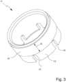
- Fig. 3 the fastening part 11 according to the first embodiment is shown.
- the fastening part 11 is preferably ring-shaped and/or at least substantially cylindrical or hollow-cylindrical or sleeve-shaped.
- the fastening part 11 preferably has a coupling section 13.
- the coupling section 13 is preferably designed for the rotationally fixed coupling of the fastening part 11 to a head or tool (not shown) during assembly.
- the head is preferably designed to be complementary to the fastening part 11 or the coupling section 13.
- the coupling portion 13 is preferably arranged or formed on a cylindrical portion or region of the fastening part 11.
- the coupling section 13 is arranged and/or formed on an end face or on an axial end of the fastening part 11 or the cylindrical section, as shown in particular in Fig. 3 is shown.
- the coupling portion 13 preferably has one or more axially extending projections or recesses 14 or is formed by them.
- the recesses 14 are preferably elongated or formed as axially extending incisions or cutouts.
- the cutouts or recesses 14 are preferably evenly distributed over the circumference of the fastening part 11.
- the fastening part 11 or the coupling section 13 has six recesses 14.
- other solutions are also possible here.
- valve 4 with the valve housing 5, the valve element 6, the return element 7 and the seal 10 is preferably arranged in the associated receptacle 9 of the valve plate 8, in particular inserted into the receptacle 9 from the inside or underside of the valve plate 8.
- the fastening part 11 is preferably pushed over the valve 4 or valve housing 5.
- valve 4 or valve housing 5 or fastening part 11 is then secured or fastened to the valve plate 8, preferably by materially bonding, in particular welding, particularly preferably friction welding, the fastening part 11 to the valve plate 8.
- Friction welding is achieved by pressing the two components to be joined together against each other and rotating them at high speed relative to each other. Due to the high rotation speed, the components to be joined heat up so much due to the friction that the components melt, or are melted or plasticized, at least on their contact surface and are thus bonded together in a material-locking manner.
- the components to be welded are preferably of the same type or made from the same or a similar material. However, if necessary, components made from different materials, such as metal and plastic parts, can also be welded together using friction welding.
- the fastening part 11 is welded radially to the valve plate 8.
- the weld seam or weld connection forms a connection that extends radially between the fastening part 11 and the valve plate 8 or a section of the valve plate 8 or runs radially or connects the fastening part 11 and the valve plate 8 radially to one another.
- the weld seam or weld connection is preferably ring-shaped and/or circumferential, in particular with respect to the axis L.
- the fastening part 11 preferably has a welding area 15.
- the welding region 15 is preferably arranged on an outer side or peripheral surface of the fastening part 11 or a cylindrical section of the fastening part 11, at least in the first embodiment.
- the welding region 15 is designed in a ring-like or bead-like manner and/or the welding region 15 surrounds the fastening part 11, in particular completely.
- the welding region 15 is designed in the form of an annular groove and/or the welding region 15 forms a thickening of the fastening part 11.
- the welding region 15 protrudes radially from the fastening part 11 or the welding region 15 protrudes radially from the fastening part 11.
- the welding region 15 preferably forms a shoulder, a step or a projection on the outside of the fastening part 11.
- the welding region 15 is designed in particular to be melted or plasticized during welding or friction welding, so that the material connection or welded connection of the fastening part 11 with the valve plate 8 is created.
- plasticizing is understood to mean in particular a process in which a material, in particular plastic or metal, is converted, preferably by heating, into a state in which it is plastically deformable.
- the welding area 15 is preferably designed to be as large as possible.
- the welding region 15 has an extension E of at least 3 mm, preferably about 5 mm or more, in the axial direction or axially or parallel to the longitudinal axis L.
- the welding area 15 is arranged centrally in the axial direction and/or at a distance from the axial end sides of the fastening part 11.
- other solutions are also possible here.
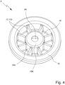
- Fig. 4 the valve disk 8 according to the first embodiment is shown.
- the valve plate 8 or the receptacle 9 preferably has a receiving space 16 for receiving the valve 4 or the valve housing 5.
- the receiving space 16 is arranged in particular centrally or in the middle and/or symmetrically to the axis L on the valve plate 8.
- the receiving space 16 is arranged on the inside of the valve plate 8.
- the receiving space 16 is preferably at least substantially cylindrical.
- the receptacle 9 is preferably formed by the receptacle space 16 and/or a wall of the valve plate 8 forming or delimiting the receptacle space 16.
- the wall of the valve plate 8 preferably has a cylindrical, in particular axially extending, wall section 16A and a circular disk-like formed transversely or perpendicularly to the longitudinal axis L, which axially delimits or closes off the receptacle 9 or the receiving space 16.
- the wall sections 16A, 16B are also referred to below for short as sections 16A, 16B.
- the cylindrical section 16A delimits the receptacle 9 or the receiving space 16 laterally or the cylindrical section 16A forms a lateral surface of the receiving space 16 or the receptacle 9.
- the circular disk-like section 16B of the wall preferably has a central opening or perforation 9A for passing the valve element 6 outwards or for pressing the valve element 6 in from the outside.
- the opening or breakthrough 9A for the valve element 6 has a smaller diameter than the receiving space 16, so that the section 16B holds or can hold the valve 4 or the valve housing 5 and the seal 10 in a form-fitting axial manner in the receptacle 9 or the receiving space 16.
- the fastening part 11, in particular together with the valve 4 or valve housing 5, is arranged in the receiving space 16, in particular radially between the valve housing 5 and the section 16A of the valve plate 8, as shown in particular in Fig. 2 recognizable.
- the outer diameter of the fastening part 11 or welding area 15 and the (inner) diameter of the receiving space 16 are preferably coordinated with one another in such a way that the outer diameter of the fastening part 11 or welding area 15 is somewhat larger, in particular by at least 0.1 mm and/or at most 2 mm, than the associated (inner) diameter of the receiving space 16 or section 16A, so that the fastening part 11 can be friction welded to the receiving space 16 or section 16A of the valve plate 8.
- the fastening part 11 can preferably not be inserted axially into the receiving space 16 without deformation, or not completely, or not up to its assembly position.
- the welding area 15 preferably protrudes radially from the fastening part 11, so that the fastening part 11 can be inserted axially a small distance into the receiving space 16 and/or centered in the receiving space 16 initially or before the friction welding process begins, until the shoulder formed by the welding area 15 comes to rest on the section 16A.
- the "too large" diameter of the fastening part 11 has the effect in particular that when the fastening part 11 rotates or when the fastening part 11 is friction-welded to the valve plate 8 while the fastening part 11 is moved axially into its assembly position, the welding area 15 is melted or plasticized by frictional heat, so that the fastening part 11 is deformed at least in the welding area 15 and can be completely inserted into the receiving space 16, whereby the fastening part 11 is bonded to the valve plate 8 in a material-locking manner.
- valve 4 or valve housing 5 is held axially in the valve plate 8 in a form-fitting manner on the one hand by the fastening part 11 and on the other hand by the section 16B of the valve plate 8.
- the valve housing 5 has, in particular on the outside, a widening or shoulder 5A or forms such a widening.
- the shoulder 5A preferably protrudes radially from the valve housing 5.
- the shoulder 5A is formed by one or more elements or ribs which protrude or protrude radially from an at least substantially cylindrical section of the valve housing 5.
- the valve housing 5 is preferably axially supported by the shoulder 5A on the fastening part 11 or vice versa.
- the shoulder 5A preferably forms a stop for the fastening part 11.
- the fastening part 11 rests firmly on the valve housing 5 and the valve housing 5 rests firmly on the valve plate 8, so that the valve housing 5 is held (at least axially) firmly or immovably between the valve plate 8 and the fastening part 11.
- valve housing 5 is preferably held firmly or immovably or positively in the receptacle 9 or the receptacle space 16 by the Ribs which have or form the shoulder 5A rest radially on the section 16A or its inner side.
- the valve plate 8 preferably has a coupling device 17.
- the coupling device 17 is preferably designed for the rotationally fixed coupling of the valve plate 8 to a tool or holder 27, so that the valve plate 8 can be held and/or rotated in a form-fitting manner during friction welding with the tool or holder 27.
- the coupling device 17 is preferably arranged on the outside of the valve plate 8.
- valve disk 8 has an annular space 18 coaxial with the axis L.
- the coupling device 17 is preferably formed or arranged in the annular space 18.
- the annular space 18 is preferably limited by the (wall) section 16A.
- the coupling device 17 is formed by or has radially extending webs, ribs or coupling elements 17A.
- the coupling elements 17A are preferably arranged or formed on the outside of the valve plate 8, in particular in the annular space 18.
- the coupling elements 17A are formed by walls or wall elements extending radially in the annular space 18, preferably wherein the coupling elements 17A divide the annular space into sectors.
- valve plate 8 in the dispensing device 1 is preferably friction-welded to the container 3.
- valve disk 8 has a collar 19 on an outer edge.
- a collar 19 on an outer edge.
- embodiments without a collar 19 are also possible, which will be discussed later in particular with reference to Fig. 10 and 12 is still being discussed.
- the collar 19 forms an annular groove open downwards or in the direction of the container 3 for receiving the edge 3C of the container 3.
- valve disk 8 is friction welded in the region of the collar 19 to a wall forming or delimiting the opening 3A of the container 3.
- the collar 19 surrounds the wall forming the opening 3A.
- a seal or a sealing ring can also be provided, which is preferably arranged in the collar 19 before the valve plate 8 is welded to the container 3, in particular to ensure a tight closure of the container 3.
- the container 3 preferably has a coupling section 20.
- the coupling section 20 is arranged in particular in a neck region 3B of the container 3 surrounding and/or forming the opening 3A.
- the coupling section 20 is preferably designed for the rotationally fixed coupling of the container 3 with a tool or holder 28 for or during the friction welding of the valve plate 8 with the container 3. This is particularly the case in Fig. 11 and 12 shown.
- the coupling section 20 is formed by or has one or more coupling elements 20A projecting radially from the container 3 or the neck region 3B.
- the coupling elements 20A can be evenly distributed on the neck region 3B or container 3. It is also possible for the coupling section to have only one coupling element 20A running around the container 3 or the opening 3A in the manner of a collar.
- the wall of the container 3 is preferably thicker or reinforced.
- a step or a projection is formed in the neck region 3B of the container 3 and/or the collar 19 of the valve plate 8, which allows easy centering or arrangement or initial guidance of the valve plate 8 in the opening 3A before friction welding.
- the weld seam or weld connection formed during friction welding between the container 3 or the neck region 3B and the valve plate 8 preferably has an axial extension of at least 3 mm, in particular 5 mm or more. This ensures a secure attachment of the valve plate 8 to the container 3.
- the propellant gas is preferably introduced under high pressure into the (fully assembled and preferably already filled with the fluid F) dispensing device 1, in which the fastening part 11 is firmly connected to the valve plate 8 and the valve plate 8 is firmly connected to the container 3. Due to the high pressure, the propellant gas G deforms the seal 10 so that a gap forms between the seal 10 and the section 16B. The propellant gas G can now first pass between the valve element 6 and the section 16B and then through the gap between the seal 10 and the section 16B. The propellant gas G then passes through channels 5C, which are formed between the ribs of the valve housing 5, which form the shoulder 5A, and the section 16A, past the valve housing 5 and the fastening part 11 into the interior of the container 3. The path of the propellant gas G when filling the dispensing device 1 is shown in Fig. 2 indicated by an arrow on the left side.
- the Fig. 5 and 6 show a dispensing device 1 according to a second embodiment.
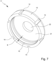
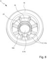
- the fastening part 11 and the valve plate 8 are shown according to the second embodiment.
- the second embodiment differs from the first embodiment by a different design of the fastening part 11 and the valve plate 8.
- the fastening part 11 is preferably designed in the form of a cap.
- a hollow cylindrical, sleeve-like or ring-like section of the fastening part 11 is adjoined at the end by an end wall 21 running transversely, in particular perpendicularly, to the axis L.
- the end wall 21 preferably has an opening 22 for the valve 4 or valve element 6, which is preferably arranged centrally or in the middle.
- the coupling section 13 has recesses 14 in the form of elongated or axially extending radial indentations of the outer edge of the fastening part 11 or its cylindrical section or is formed by these.
- recesses 14 in the form of elongated or axially extending radial indentations of the outer edge of the fastening part 11 or its cylindrical section or is formed by these.
- other solutions are also conceivable here, for example radial projections.
- the recesses 14 or indentations are preferably arranged symmetrically on the fastening part 11.
- the fastening part 11 or the coupling section 13 has six recesses 14.
- other solutions are also possible here.
- the fastening part 11 is arranged on the outside of the valve plate 8.
- valve 4 with the valve housing 5, the valve element 6, the return element 7 and the seal 10 is preferably arranged in the associated receptacle 9 of the valve plate 8, in particular inserted into the receptacle from the outside or top of the valve plate 8.
- the fastening part 11 is preferably pushed over the valve 4 or valve housing 5.
- valve 4 or valve housing 5 is then preferably secured or fastened to the valve plate 8.
- the securing or fastening of the valve 4 or valve housing 5 to the valve plate 8 is preferably carried out by materially bonding, in particular welding, the fastening part 11 to the valve plate 8.
- the fastening part 11 is friction welded to the valve plate 8.
- valve plate 8 according to the second embodiment differs from the valve plate 8 according to the first embodiment preferably (mainly) in the design or construction of the receptacle 9 and/or the receptacle space 16.
- the receptacle 9 or the receptacle space 16 is at least substantially cylindrical.
- the receptacle space 16 or the receptacle 9 is preferably not delimited on one side by a (wall) section 16B of the valve disk 8 running transversely to the longitudinal axis L.
- the function of the section 16B is preferably taken over by the cover surface 21 of the fastening part 11.
- a support surface 23 or a projection is formed or arranged in the receptacle 9 or the receiving space 16. Due to the support surface 23, the diameter of the receiving space 16 is preferably reduced in the region of the support surface 23.
- the support surface 23 can be formed by several individual elements arranged in the receiving space 16.
- the support surface 23 is preferably designed as a one-piece circumferential ring or axial stop for the shoulder 5A of the valve housing 5.
- the support surface 23 is preferably designed to hold the valve 4 or valve housing 5 in an axially positive manner in the receptacle 9 or the receiving space 16 or to prevent the valve 4 or valve housing 5 from slipping through the receptacle 9 or the receiving space 16.
- the support surface 23 is preferably designed to rest on the shoulder 5A of the valve housing 5 or is assigned to the shoulder 5A of the valve housing 5.
- the support surface 23 preferably forms a stop.
- the support surface 23 preferably at least partially takes over the function of the fastening part 11 in the first embodiment, which holds the valve housing 5 in a form-fitting manner by supporting it on the shoulder 5A of the valve housing 5 in the receptacle 9 or the receptacle space 16.
- the fastening part 11 has the welding area 15 preferably on an inner side or on an inner edge of the cylindrical section.
- the welding area 15 preferably protrudes radially inward from the fastening part 11 or cylindrical section.
- the welding region 15 in the fastening part 11 according to the second embodiment is not arranged or formed axially offset or displaced relative to the coupling section 13 on the fastening part 11.
- the welding region 15 is preferably arranged on an inner side or inner surface of the fastening part 11 or a cylindrical portion of the fastening part 11.
- the inner side of the fastening part 11 is preferably welded to the wall section 16A, which forms the inner boundary or an inner wall of the annular space 18.
- the inner diameter of the fastening part 11 or welding area 15 and the (outer) diameter of the section 16A are preferably coordinated with one another in such a way that the inner diameter of the fastening part 11 or welding area 15 is somewhat smaller, in particular by at least 0.1 mm and/or at most 2 mm, than the (outer) diameter of the section 16A, so that the fastening part 11 can be friction welded to the section 16A.
- the fastening part 11 can therefore preferably not be pushed over the section 16A or the receiving space 16 without deformation.
- the "too small" diameter of the fastening part 11 has the effect in particular that when the fastening part 11 rotates or when the fastening part 11 is friction-welded to the valve plate 8, the welding area 15 is melted or plasticized by frictional heat, so that the fastening part 11 is deformable at least in the welding area 15 and can be pushed over the receiving space 16, whereby the fastening part 11 is firmly bonded to the valve plate 8 or its wall section 16A.
- the fastening part 11 is laser-welded or ultrasonically welded to the valve plate 8 instead of friction-welded.
- the fastening part 11 has a first section 24 and a second section 25.
- the first section 24 is cylindrical or hollow-cylindrical. However, the first section 24 can also be slightly conical. In this way, a clamping effect can be achieved when the fastening part 11 or the first section 24 is introduced into the receiving space 16 of the valve plate 8.
- the second section 25 projects radially from the first section 24.
- the second section 25 is arranged at least substantially at right angles to the first section 24.
- the second portion 25 is preferably arranged at an axial end of the fastening part 11.
- the second portion 25 is preferably flange- or collar-like.
- the second portion 25 is designed to rest against the lower or radially extending boundary surface of the annular space 18 of the valve disk 8.
- the fastening part 11, in particular the second section 25, preferably has the welding area 15.
- the welding area 15 is designed in a ring-like manner and/or is arranged coaxially to the first section 24.
- the welding area 15 it is possible for the welding area 15 to be formed by several non-connected, in particular small-area and/or point-like, elevations, so that no continuous weld seam 26 is formed during welding, but only point-like weld connections.
- the welding area 15 is rectangular (in cross section).
- the welding area 15 can also, as in particular in Fig. 9 B shown, have a triangular cross-section.
- other shapes of the cross-section of the welding area 15 are also possible, for example round, in particular semicircular, or other cross-sections.
- the welding area 15 is designed in particular to plasticize during laser welding or ultrasonic welding and thus to form a weld seam 26 between the fastening part 11 and the valve plate 8. It is particularly possible that the fastening part 11 welded to the valve plate 8 does not lie on the valve plate 8 over its entire surface, but preferably only in the area of the weld seam 26. This makes it possible to compensate for unevenness and/or tolerances of the valve plate 8 and/or the fastening part 11. This reliably ensures that in particular the seal 10 is firmly clamped and the valve housing 5 sits in the valve plate 8 without play and is clamped between the valve plate 8 and the fastening part 11 without play.
- the welding area 15 preferably forms a raised portion or a material surplus of the second section 25.
- the (axial) thickness or height of the welding area 15 is preferably more than 0.2 mm and/or less than 1.2 mm, in particular approximately 0.8 mm. This preferably makes it possible to compensate for unevenness of the valve plate 8 and/or the fastening part 11 and/or axial tolerances.
- valve 4 is first inserted into the receptacle 9 or the receiving space 16, in particular from the inside of the valve plate 8.
- the fastening part 11 is then also inserted into the receptacle 9 or the receiving space 16, so that the valve 4 is arranged between the valve plate 8 and the fastening part 11, in particular clamped between them.
- valve plate 8, the valve 4 or valve housing 5 and the fastening part 11 are preferably dimensioned or coordinated with one another in such a way that the second section 25 or the welding region 15 rests against an underside of the valve plate 8, in particular flatly, when the fastening part 11 is completely inserted into the receptacle 9 or the receiving space 16 and the valve 4 is clamped between the valve plate 8 and the fastening part 11.
- the valve plate 8 is made of a laser-absorbing and/or dark, in particular black, material and the fastening part 11 or at least the second section 25 is made of a transparent, in particular laser-transparent, material, so that the valve plate 8 can be irradiated with a laser through the fastening part 11 to produce the welded connection with the fastening part 11.
- the laser beam can therefore preferably pass through the fastening part 11 without being absorbed.
- a laser transmission welding process or an ultrasonic welding process is preferably used.
- the valve plate 8 or its inner side is irradiated with a laser through the fastening part 11.
- the material is heated as a result.
- the laser beam passes through the welding area 15 and/or the laser beam is directed at the welding area 15. Due to the absorption in the valve plate 8, the material of the valve plate 8 is heated and thus melted or plasticized. This takes place in particular in the immediate vicinity or on the contact surface with the welding area 15.
- Heat conduction processes preferably also heat up and thus melt or plasticize the welding area 15, so that a weld seam 26 is created between the valve plate 8 and the fastening part 11 and the valve plate 8 and the fastening part 11 are connected to one another in a materially bonded manner.
- valve plate 8 and the fastening part 11 are preferably each made of a plastic, in particular PET.
- a high-power diode laser preferably with a wavelength of more than 900 nm and/or less than 1100 nm, or a solid-state laser, in particular a fiber laser or Nd:YAG laser, preferably with a wavelength of more than 1060 nm and/or less than 1090 nm, is used for laser welding.
- valve plate is laser welded or ultrasonically welded to the fastening part 11 and the valve arrangement 2 thus provided is particularly preferably friction welded to the container 3, as described above.
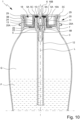
- valve disk 8 is designed without a collar or does not have a collar 19 for the edge 3C of the container 3. This is particularly the case in the Fig. 10 and 12 In this case, the valve disk 8 preferably ends (axially) flush with the container 3 or the edge 3C of the container.
- valve plate 8 or the valve arrangement 2 is first inserted into the container 3.
- the valve plate 8 can be inserted in a defined position or rotational position relative to the container 3.
- valve arrangement 2 When connecting the valve arrangement 2 to the container 3, the valve arrangement 2 is preferably held with a first holder or tool 27 and the container 3 is preferably held with a second holder or tool 28. This is shown schematically in the Fig. 11 and 12 shown.
- the coupling element 20A is designed as a collar or radially protruding element that surrounds the container 3 or the opening 3A.
- the coupling element 20A preferably has one or more engagement elements, in particular those that lie opposite one another, that are designed to engage with the holder 28.
- the engagement elements are formed by recesses.
- the container 3 and the valve arrangement 2 are moved axially towards one another and simultaneously rotated relative to one another about the axis L.
- one of the parts, preferably the container 3 is held in a fixed position and the other part, preferably the valve arrangement 2, is rotated relative thereto about the axis L.
- valve plate 8 is preferably held and/or turned or rotated by means of a tool 27 which positively engages the valve plate 8 or its coupling device 17 and/or holds or grips the valve plate 8 on the coupling elements 17A.
- valve plate 8 and the container 3 are preferably moved axially towards one another until the valve plate 8 has reached a defined end position or axial position relative to the container 3.
- the valve plate 8 is preferably designed without a collar or the valve plate 8 does not have a collar 19.
- valve disk 8 in the end position or defined axial position is axially flush with the container 3 or its edge 3C.
- other solutions are also possible here.
- a flush closure makes it possible to reliably check the connection between the container 3 and the valve plate 8 or the valve arrangement 2 in a simple manner, since the flush closure or defined seat of the valve plate 8 is an indication of the correct or faultless connection. In particular, it is an indication of a faulty connection or welded connection if, after the connection has been made, the (collarless) valve plate 8 does not close axially flush with the edge 3C of the container.
- a defined number of revolutions for example exactly 12 revolutions, are carried out during friction welding of the container 3 to the valve plate 8. This ensures efficient, fast and reproducible connection or welding of the valve arrangement 2 to the container 3.
- a particularly ring-like and/or radial welding surface 29 is preferably created.
- the welding surface is in particular the area in which the material of the container 3 and/or the valve plate 8 is plasticized during friction welding and thus forms the material-locking connection or weld.
- the width of the welding surface 29 or the extension of the welding surface 29 in the radial direction is preferably more than 0.1 mm and/or less than 0.5 mm, in particular approximately 0.3 mm.
- the length of the weld seam 29 or the extension of the weld seam 29 in the axial direction is preferably more than 0.5 mm, in particular more than 1 mm, and/or less than 2 mm, in particular less than 1.5 mm.
- the dispensing device 1 preferably has a dispensing head (not shown in the figures) for dispensing the fluid F.
- the edge 3C is preferably thickened and designed like a collar or flange.
- the edge 3C protrudes in particular radially from the neck region 3B.
- the dispensing head is positively connected to the edge 3C or fastened thereto.
- the dispensing head can be supported on the edge 3C and/or the valve plate 8, in particular if the valve plate 8 is flush with the edge 3C.
- the coupling element 20A can be omitted or can be formed by the (thickened) edge 3C. In this case, it is not necessary to provide a coupling element 20A in addition to the edge 3C.
- the edge 3C then preferably has the features described above for the coupling element 20A.
Landscapes
- Engineering & Computer Science (AREA)
- Mechanical Engineering (AREA)
- Chemical & Material Sciences (AREA)
- Dispersion Chemistry (AREA)
- Containers And Packaging Bodies Having A Special Means To Remove Contents (AREA)
- Valve Housings (AREA)
- Nozzles (AREA)
- Feeding, Discharge, Calcimining, Fusing, And Gas-Generation Devices (AREA)
Description
- Die vorliegende Erfindung betrifft eine Ventilanordnung zur Abgabe eines Fluids nach dem Oberbegriff des Anspruchs 1, eine Abgabevorrichtung zur Abgabe eines Fluids nach dem Oberbegriff des Anspruchs 8 sowie ein Verfahren zur Herstellung einer Ventilanordnung nach dem Oberbegriff des Anspruchs 11.
- Insbesondere betrifft die vorliegende Erfindung das Gebiet der Aerosolbehälter, also Behälter, in denen ein unter Druck stehendes Fluid aufgenommen ist, das als Aerosol abgegeben bzw. versprüht werden kann. Derartige Behälter können insbesondere für Hygiene-, Pflege- und Kosmetikprodukte eingesetzt werden, beispielsweise Deodorants oder Haarsprays.
- Grundsätzlich ist die vorliegende Erfindung jedoch vielseitig einsetzbar und kann auf beliebigen technischen Gebieten eingesetzt werden, in denen eine (dosierte) Abgabe eines Fluids aus einem Behälter erfolgt.
- Die
WO 89/08062 A2 - Die
EP 2 894 114 A1 offenbart eine Ventilbaugruppe für Aerosolbehälter mit einem Ventilteller, einem Ventilelement und einem Ventilgehäuse für das Ventilelement. An der Oberseite des Ventiltellers ist ein Deckel angeordnet, der eine Montageöffnung des Ventilgehäuses verschließt und an dem Ventilteller befestigt ist, beispielsweise durch eine Schweißverbindung. Der Ventilteller und der Deckel bestehen aus Kunststoff. - Die
EP 2 832 661 A1 offenbart einen Aerosolbehälter, dessen Behälteröffnung durch einen Ventilteller mit einem Abgabeventil verschlossen ist, wobei der Ventilteller aus Kunststoff besteht. An der Innenseite des Ventiltellers ist ein formstabiler Fortsatz angeformt, der einen Aufnahmeraum für ein Ventilgehäuse des Abgabeventils bildet. Der Fortsatz und das Ventilgehäuse sind durch mindestens ein separates Sicherungselement verbunden. - Die
WO 2016/202754 A1 betrifft eine Ventilanordnung für einen Aerosolbehälter. Ein Ventilteller und ein Ventilgehäuse der Ventilanordnung sind durch ein einstückiges Bauteil gebildet, in das eine Feder, eine Dichtung und ein Ventilelement von der dem Behälter abgewandten Außenseite eingesetzt werden und durch einen im Wesentlichen scheibenartigen Haltering an dem Ventilteller fixiert werden. Der Haltering wird mit dem Ventilteller axial ultraschallverschweißt. - Die
WO 2017/021038 A1 betrifft eine Ventilanordnung und einen Behälter zur Abgabe eines Fluids. Ein Ventilteller der Ventilanordnung besteht aus semikristallinem Polyester. Er kann generell durch Reibschweißen, Ultraschallschweißen oder Laserschweißen mit einem Behälter verbunden werden, wobei ein Kragen des Ventiltellers einen Rand des Behälters umgreift. - Die
WO 03/062092 A1 - Die
US 5,573,043 A betrifft einen Ventilteller für einen unter Druck stehenden Spender, wobei eine dichtende Verbindung zwischen Ventilteller und einem Druckbehälter durch Verschweißen, insbesondere Reib- oder Ultraschallverschweißen, hergestellt wird. Eine Ventilanordnung wird über ein Paar ineinandergreifender Hülsen am Ventilteller befestigt. - Die
US 2012/292338 A1 betrifft Aerosol-Spender und deren Herstellung. Der Spender weist einen Druckbehälter mit einem Ventilteller auf, wobei der Ventilteller eine Öffnung zum Aufnehmen einer Ventilanordnung und einen Flüssigkeitsbeutel oder eine Flüssigkeitsleitung aufweist. - Es ist eine Aufgabe der vorliegenden Erfindung, eine flexible Verwendung eines herkömmlichen Ventils und/oder eine einfache und kostengünstige Produktion einer Ventilanordnung bzw. Abgabevorrichtung zu ermöglichen.
- Die obige Aufgabe wird gelöst durch eine Ventilanordnung gemäß Anspruch 1, eine Abgabevorrichtung gemäß Anspruch 8, oder ein Verfahren gemäß Anspruch 11. Vorteilhafte Weiterbildungen sind Gegenstand der Unteransprüche.
- Insbesondere wird durch die vorliegende Erfindung eine besonders einfache Möglichkeit angegeben, mit der ein an sich bekanntes bzw. herkömmliches Ventil wahlweise mit verschiedenen Ventiltellern, die wahlweise aus Kunststoff oder Metall bestehen können, eingesetzt bzw. verwendet werden kann, ohne dass dazu das Ventil an sich angepasst werden muss. Dies ermöglicht eine einfache und kostengünstige Produktion bzw. Montage. Des Weiteren wird die Flexibilität bei der Herstellung einer Ventilanordnung bzw. Abgabevorrichtung erhöht, da unterschiedliche Teile, insbesondere Ventilteller, mit dem gleichen Standardventil verwendet werden können.
- Eine vorschlagsgemäße Ventilanordnung ist zur Abgabe eines Fluids, insbesondere aus einem Behälter, ausgebildet. Die Ventilanordnung weist einen Ventilteller zur Befestigung der Ventilanordnung an einem zugeordneten Behälter auf. Ferner weist die Ventilanordnung ein Ventilgehäuse und ein Befestigungsteil zur Befestigung des Ventilgehäuses an dem Ventilteller auf. Vorzugsweise ist das Befestigungsteil ein von dem Ventilgehäuse separates Bauteil. Hierdurch ist eine Verwendung eines Standardventils mit unterschiedlichen Ventiltellern ermöglicht.
- Vorzugsweise bestehen der Ventilteller, das Befestigungsteil, das Ventilgehäuse, ein Ventilelement der Ventilanordnung und/oder eine Feder der Ventilanordnung und/oder die Ventilanordnung insgesamt aus Kunststoff, insbesondere PET. Dies ermöglicht eine kostengünstige Produktion.
- Es ist bevorzugt, dass das Ventilgehäuse mit dem Ventilelement, der Dichtung und optional mit dem Rückstellelement formschlüssig zu einem Ventil verbindbar ist. Insbesondere sind das Ventilgehäuse, das Ventilelement, die Dichtung und optional das Rückstellelement derart miteinander verbindbar bzw. zusammenfügbar, dass sie bei normalem Gebrauch bzw. ohne äußere Einwirkung verbunden bleiben bzw. nicht auseinander fallen, so dass das Ventil als Ganzes bzw. als vormontiertes Bauteil in den Ventilteller einsetzbar und mit diesem verbindbar ist. Insbesondere wird hierdurch die Montage erleichtert.
- Bei der vorschlagsgemäßen Ventilanordnung ist das Befestigungsteil mit dem Ventilteller laserverschweißt oder ultraschallverschweißt.
- Das Befestigungsteil weist einen ersten zylindrischen oder konischen Abschnitt und einen zweiten radial davon abragenden Abschnitt auf. Hierdurch kann eine für einen Laserstrahl leicht zugängliche Kontaktfläche zwischen dem Ventilteller und dem Befestigungsteil gebildet werden.
- Der erste Abschnitt ist in einen Aufnahmeraum des Ventiltellers eingeführt und der zweite Abschnitt liegt an einer Unterseite des Ventiltellers an.
- Das Ventilgehäuse ist ohne Spiel zwischen dem Ventilteller und dem Befestigungsteil eingeklemmt.
- Das Befestigungsteil weist vorzugsweise einen Verschweißbereich auf. Der Verschweißbereich ist insbesondere an dem zweiten Abschnitt angeordnet. Vorzugsweise weist der Verschweißbereich einen dreieckigen oder rechteckigen Querschnitt auf.
- Es ist besonders bevorzugt, dass der Ventilteller aus einem laserabsorbierenden und/oder dunklen, insbesondere schwarzen, Material hergestellt ist und das Befestigungsteil aus einem transparenten, insbesondere lasertransparenten, Material hergestellt ist. Hierdurch wird ein Laserverschweißen und/oder ein Ultraschallschweißen des Befestigungsteils mit dem Ventilteller auf einfache Weise ermöglicht.
- Gemäß einem weiteren Aspekt betrifft die vorliegende Erfindung eine Abgabevorrichtung zur Abgabe eines Fluids. Die Abgabevorrichtung weist einen Behälter und eine vorschlagsgemäße Ventilanordnung mit einem an dem Behälter befestigten Ventilteller auf.
- Vorzugsweise ist der Ventilteller mit dem Behälter reibverschweißt und/oder radial verschweißt.
- Vorzugsweise schließt der Ventilteller axial bündig mit dem Behälter ab.
- Bevorzugt besteht die Ventilanordnung, insbesondere der Ventilteller, und/oder der Behälter aus Kunststoff, insbesondere PET. Dies ermöglicht eine kostengünstige Produktion.
- Der Ventilteller weist vorzugsweise eine Kopplungseinrichtung auf, die zur drehfesten Kopplung des Ventiltellers mit einem Werkzeug bzw. Halter zum Reibverschweißen des Ventiltellers mit dem Behälter ausgebildet ist. Die Kopplungseinrichtung ist vorzugsweise durch, insbesondere auf der Oberseite des Ventiltellers angeordnete, vorzugsweise sich radial erstreckende Kopplungselemente gebildet oder weist diese auf. Die Kopplungselemente sind besonders bevorzugt in einer insbesondere ringartigen Vertiefung des Ventiltellers angeordnet. Dies ermöglicht auf einfache Weise eine zuverlässige Kopplung.
- Der Behälter weist vorzugsweise einen Kopplungsabschnitt auf, der zur drehfesten Kopplung mit einem Werkzeug bzw. Halter zum bzw. beim Reibverschweißen des Ventiltellers mit dem Behälter ausgebildet ist. Der Kopplungsabschnitt ist insbesondere in oder an einem Halsbereich des Behälters angeordnet.
- Vorzugsweise weist der Kopplungsabschnitt ein oder mehrere radial von dem Behälter abragende Kopplungselemente auf oder ist dadurch gebildet. Dies ermöglicht auf einfache Weise eine zuverlässige Kopplung.
- Gemäß einem weiteren, auch unabhängig realisierbaren Aspekt betrifft die vorliegende Erfindung ein Verfahren zur Herstellung einer Ventilanordnung, wobei das Befestigungsteil mit dem Ventilteller laserverschweißt oder ultraschallverschweißt wird.
- Das Ventil wird erst in eine zugeordnete Aufnahme des Ventiltellers eingeführt und anschließend wird das Befestigungsteil in die Aufnahme eingeführt bzw. eingesetzt, so dass das Ventil zwischen dem Ventilteller und dem Befestigungsteil angeordnet, insbesondere eingeklemmt, ist und das Befestigungsteil an dem Ventilteller anliegt. Vorzugsweise wird der Ventilteller dann durch das Befestigungsteil hindurch von einem Laserstrahl bestrahlt, so dass der Ventilteller und das Befestigungsteil miteinander verschweißt werden.
- Bei einem bevorzugten, nicht beanspruchten Verfahren zur Herstellung einer Abgabevorrichtung wird der Ventilteller mit dem Behälter reibverschweißt, so dass der Ventilteller mit dem Behälter radial verschweißt wird und/oder axial bündig abschließt.
- Weitere Aspekte, Merkmale, Vorteile und Eigenschaften der vorliegenden Erfindung ergeben sich aus den Ansprüchen und der nachfolgenden Beschreibung bevorzugter Ausführungsformen anhand der Zeichnung. Hierbei fallen die erste und zweite Ausführungsform nicht unter den Wortlaut der Ansprüche, werden aber als das Verständnis der Erfindung erleichternd angesehen. Alle Merkmale der ersten und zweiten Ausführungsform können auch bei Ausführungsformen, die unter den Wortlaut der Ansprüche fallen, realisiert sein, sofern sie nicht im Widerspruch dazu stehen. Es zeigt:
- Fig. 1
- eine Explosionsdarstellung einer Abgabevorrichtung gemäß einer ersten nicht erfindungsgemäßen Ausführungsform;
- Fig. 2
- einen Schnitt der Abgabevorrichtung von
Fig. 1 im montierten Zustand; - Fig. 3
- eine perspektivische Darstellung eines Befestigungsteils gemäß der ersten Ausführungsform;
- Fig. 4
- eine perspektivische Darstellung eines Ventiltellers gemäß der ersten Ausführungsform;
- Fig. 5
- eine Explosionsdarstellung einer Abgabevorrichtung gemäß einer zweiten nicht erfindungsgemäßen Ausführungsform;
- Fig. 6
- einen Schnitt der Abgabevorrichtung von
Fig. 5 im montierten Zustand; - Fig. 7
- eine perspektivische Darstellung eines Befestigungsteils gemäß der zweiten Ausführungsform;
- Fig. 8
- eine perspektivische Darstellung eines Ventiltellers gemäß der zweiten Ausführungsform;
- Fig.9A
- eine perspektivische Darstellung eines Befestigungsteils gemäß einer dritten erfindungsgemäßen Ausführungsform;
- Fig. 9B
- eine perspektivische Darstellung eines Befestigungsteils gemäß einer vierten erfindungsgemäßen Ausführungsform;
- Fig. 10
- einen Schnitt der Abgabevorrichtung gemäß der dritten bzw. vierten Ausführungsform;
- Fig. 11
- einen Schnitt eines Behälters der Abgabevorrichtung im Bereich eines Kopplungselements; und
- Fig. 12
- einen Schnitt der Abgabevorrichtung gemäß
Fig. 10 mit zusätzlich angedeuteten Werkzeugen. - In den Figuren werden für gleiche oder gleichartige Komponenten und Einrichtungen die gleichen Bezugszeichen verwendet, wobei sich die gleichen oder entsprechende Vorteile und Eigenschaften ergeben können, auch wenn eine wiederholte Beschreibung weggelassen ist.
-
Fig. 1 und2 zeigen eine Abgabevorrichtung 1 gemäß einer ersten Ausführungsform.Fig. 2 zeigt die Abgabevorrichtung 1 gemäß der ersten Ausführungsform in einem fertig montierten Zustand. - Die Abgabevorrichtung 1 weist eine Ventilanordnung 2 und einen Behälter 3 auf. Die Ventilanordnung 2 ist vorzugsweise zumindest teilweise in einer Öffnung 3A des Behälters 3 anordenbar bzw. angeordnet. Insbesondere wird bei der (fertig montierten) Abgabevorrichtung 1 der Behälter 3 bzw. dessen Öffnung 3A durch die Ventilanordnung 2 verschlossen oder abgedichtet.
- Die Ventilanordnung 2 weist ein Ventil 4 und einen Ventilteller 8 auf.
- Das Ventil 4 weist ein Ventilgehäuse 5, ein bewegbares Ventilelement 6 und vorzugsweise ein Rückstellelement 7 auf. Beim Darstellungsbeispiel ist vorzugsweise das Rückstellelement 7 als Druckfeder und/oder als Schraubenfeder ausgebildet.
- Abweichend vom Darstellungsbeispiel kann das Rückstellelement 7 jedoch auch eine beliebige andere geometrische Form aufweisen, durch die eine (elastische) Rückstellkraft bzw. Federkraft realisierbar bzw. realisiert ist. Das Rückstellelement 7 kann aus Kunststoff oder Metall bestehen.
- Das Ventilelement 6 ist vorzugsweise innerhalb des Ventilgehäuses 5 bzw. axial zu dem Ventilgehäuse 5 bewegbar. Vorzugsweise ist das Ventilelement 6 mittels des Rückstellelements 7 in eine Position vorgespannt, in der das Ventilelement 6 das Ventil 4 schließt bzw. in der das Ventil 4 geschlossen ist.
- Unter einer "axialen" Richtung bzw. Bewegung wird bei der vorliegenden Erfindung eine Richtung bzw. Bewegung verstanden, die entlang oder parallel zu einer Hauptabgaberichtung oder Zentral- bzw. Längsachse L der Abgabevorrichtung 1 verläuft. In analoger Weise bezieht sich die Bezeichnung "radial" vorzugsweise ebenfalls auf die Achse L.
- Der Schnitt durch Ventilgehäuse 5 verläuft in den Figuren links der Achse L in einer anderen Ebene als rechts der Achse L, nämlich zwischen zwei der in Figuren erkennbaren, außen an dem Ventilgehäuse angeordneten Rippen anstatt durch eine der Rippen. Dadurch ist insbesondere in
Fig. 2 der Weg des Fluids beim später noch erläuterten Befüllen der Abgabevorrichtung 1 besser erkennbar. - Der Ventilteller 8 ist vorzugsweise zur Aufnahme bzw. Halterung des Ventils 4 und/oder zur Befestigung des Ventils 4 an dem Behälter 3 ausgebildet bzw. vorgesehen.
- Der Ventilteller 8 weist vorzugsweise eine Aufnahme 9 zur Aufnahme des Ventils 4 auf. Die Aufnahme 9 weist vorzugsweise eine mittig bzw. zentral angeordnete Öffnung oder Durchbrechung 9A auf.
- Vorzugsweise wird bzw. ist der Behälter 3 bzw. dessen Öffnung 3A mittels des Ventiltellers 8 fluidisch und/oder gasdicht verschlossen und/oder abgedichtet.
- Ferner weist die Ventilanordnung 2 bzw. das Ventil 4 vorzugsweise eine Dichtung 10 zur Abdichtung des Ventils 4 gegen den Ventilteller 8 auf. Die Dichtung 10 ist vorzugsweise ringartig und/oder scheibenartig ausgebildet.
- Die Dichtung 10 ist vorzugsweise verformbar und/oder besteht vorzugsweise aus einem flexiblen und/oder elastisch verformbaren Material.
- Vorzugsweise sind das Ventilgehäuse 5, das Ventilelement 6, die Dichtung 10 und optional das Rückstellelement 7 miteinander verbindbar bzw. zusammenfügbar, so dass das Ventil 4 vormontiert werden kann. Insbesondere bildet das so vormontierte Ventil 4 eine zusammenhängende Baugruppe, die als Ganzes in den Ventilteller 8 eingesetzt werden kann. Mit anderen Worten sind das Ventilgehäuse 5, das Ventilelement 6, die Dichtung 10 und das Rückstellelement 7 vorzugsweise derart zusammenfügbar bzw. vormontierbar, dass das Ventil 4 bei der Montage der Ventilanordnung 2 bzw. der Abgabevorrichtung 1 als zusammenhängendes Ventil 4 handhabbar sind, insbesondere ohne dass sich die Teile während der Montage voneinander trennen. Dies ist einer einfachen Handhabung zuträglich, da die Anzahl an zu handhabenden einzelnen Bauteilen bei der Montage verringert wird.
- Vorzugsweise weist die Ventilanordnung 2 ein (separat hergestelltes) Befestigungsteil 11 zur Befestigung des Ventils 4 bzw. Ventilgehäuses 5 an dem Ventilteller 8 auf. Das Befestigungsteil 11 ist vorzugsweise stoffschlüssig mit dem Ventilteller 8 verbindbar bzw. verbunden.
- Das Ventilgehäuse 5, das Ventilelement 6, das Rückstellelement 7, der Ventilteller 8, die Dichtung 10 und das Befestigungsteil 11 bilden vorzugsweise jeweils voneinander baulich getrennte bzw. separat hergestellte Bauteile.
- Vorzugsweise bestehen der Ventilteller 8, das Befestigungsteil 11, die Ventilanordnung 2, das Ventil 4, das Ventilgehäuse 5, das Ventilelement 6, das Rückstellelement 7 und/oder der Behälter 3 aus Kunststoff, insbesondere PET bzw. Polyethylenterephthalat.
- Vorzugsweise ist der Behälter 3 bzw. die Abgabevorrichtung 1, insbesondere nach Montage der Ventilanordnung 2, mit einem Fluid F befüllbar. Vorzugsweise wird die Abgabevorrichtung 1 bzw. der Behälter 3 zusätzlich zu dem Fluid F mit einem Druckgas bzw. Treibgas G befüllt, so dass das Fluid F in dem Behälter 3 bzw. der Abgabevorrichtung 1 unter Druck steht. Vorzugsweise herrscht in der Abgabevorrichtung 1 ein durch das Treibgas G bewirkter Überdruck.
- Ferner kann die Abgabevorrichtung 1 in den Figuren nicht dargestellte weitere Mittel für die Abgabe des Fluids F aufweisen, insbesondere in Form einer Düse, eines Sprühkopfs o. dgl. Dies ermöglicht insbesondere die (kontrollierte) Abgabe des Fluids F in einer gewünschten Abgabeform, beispielsweise als Schaum oder Spray bzw. Aerosol, und/oder die Erzeugung einer gewünschten Abgabeform.
- Das Ventil 4 ist vorzugsweise öffenbar und schließbar, insbesondere durch eine Bewegung des Ventilelements 6 relativ und/oder axial zu dem Ventilgehäuse 5.
- Vorzugsweise wird zur Abgabe des Fluids F das Ventilelement 6 entgegen der Kraft des Rückstellelements 7 bzw. der Feder in das Ventilgehäuse 5 hineingedrückt bzw. -bewegt, vorzugsweise beispielsweise mittels eines nicht dargestellten Abgabe- oder Sprühkopfs, der insbesondere auf das freie Ende des Ventilelements 6 aufgesteckt oder daran angeschlossen sein kann, so dass sich das Ventil 4 öffnet. Der Druck des Treibgases G treibt dann das Fluid F durch das Ventil 4 aus dem Behälter 3 aus.
- Vorzugsweise ist eine an dem Ventil 4 bzw. Ventilgehäuse 5 angeordnete bzw. angeschlossene Zuführung bzw. Steigleitung 12 vorgesehen, durch die das Fluid F bei der Abgabe zunächst aufsteigen kann, um bei der üblichen Gebrauchslage mit nach unten weisendem Behälter 3 über das Ventil 4 ausgegeben zu werden.
- Bei der Abgabe gelangt das Fluid F von der Steigleitung 12 in einen Innenraum 5B des Ventilgehäuses 5. Beim Herunterdrücken des Ventilelements 6 wird vorzugsweise ein Querkanal bzw. radial verlaufender Kanal 6A des Ventilelements 6 freigegeben, der im verschlossenen Zustand des Ventils 4 durch die Dichtung 10 abgedichtet ist. Nach dem Durchtritt durch den Kanal 6A tritt das Fluid F oben aus dem Ventilelement 6 heraus. Der Weg des Fluids F bei der Abgabe ist in der rechten Seite in
Fig. 2 durch einen Pfeil angedeutet. - Das Ventil 4, insbesondere das Ventilgehäuse 5, ist vorzugsweise mittels des Befestigungsteils 11 an dem Ventilteller 8 gehalten bzw. befestigt.
- Der Ventilteller 8 weist vorzugsweise eine Innenseite und eine Außenseite auf. Die Innenseite des Ventiltellers 8 ist die Seite, die dem Innenraum des Behälters 3 zugeordnet ist bzw. nach erfolgter Montage dem Innenraum des Behälters 3 zugewandt ist. In
Fig. 1 und2 ist die untere Seite bzw. Unterseite des Ventiltellers 8 die Innenseite. Die Außenseite des Ventiltellers 8 ist die dem Innenraum des Behälters 3 abgewandte Seite des Ventiltellers 8. In denFig. 1 und2 ist die obere Seite bzw. Oberseite des Ventiltellers 8 die Außenseite. - In
Fig. 3 ist das Befestigungsteil 11 gemäß der ersten Ausführungsform abgebildet. - Das Befestigungsteil 11 ist vorzugsweise ringartig und/oder zumindest im Wesentlichen zylindrisch bzw. hohlzylindrisch oder hülsenartig ausgebildet.
- Vorzugsweise weist das Befestigungsteil 11 einen Kopplungsabschnitt 13 auf. Der Kopplungsabschnitt 13 ist vorzugsweise zur drehfesten Kopplung des Befestigungsteils 11 mit einem (nicht dargestellten) Kopf bzw. Werkzeug bei der Montage ausgebildet. Der Kopf ist vorzugsweise komplementär zu dem Befestigungsteil 11 bzw. dem Kopplungsabschnitt 13 ausgebildet.
- Der Kopplungsabschnitt 13 ist vorzugsweise an einem zylindrischen Abschnitt bzw. Bereich des Befestigungsteils 11 angeordnet oder gebildet.
- Besonders bevorzugt ist der Kopplungsabschnitt 13 an einer Stirnseite bzw. an einem axialen Ende des Befestigungsteils 11 bzw. des zylindrischen Abschnitts angeordnet und/oder gebildet, wie insbesondere in
Fig. 3 dargestellt ist. - Der Kopplungsabschnitt 13 weist vorzugsweise ein oder mehrere, sich axial erstreckende Vorsprünge oder Ausnehmungen 14 auf oder ist durch diese gebildet.
- Beim Darstellungsbeispiel gemäß
Fig. 3 sind die Ausnehmungen 14 vorzugsweise länglich bzw. als sich axial erstreckende Einschnitte oder Ausschnitte gebildet. - Die Ausschnitte bzw. Ausnehmungen 14 sind vorzugsweise gleichmäßig über den Umfang des Befestigungsteils 11 verteilt. Beim Darstellungsbeispiel gemäß
Fig. 3 weist das Befestigungsteil 11 bzw. der Kopplungsabschnitt 13 sechs Ausnehmungen 14 auf. Hier sind jedoch auch andere Lösungen möglich. - Zur Montage der Ventilanordnung 2 gemäß der ersten Ausführungsform wird vorzugsweise das Ventil 4 mit dem Ventilgehäuse 5, dem Ventilelement 6, dem Rückstellelement 7 und der Dichtung 10 in der zugeordneten Aufnahme 9 des Ventiltellers 8 angeordnet, insbesondere von der Innenseite bzw. Unterseite des Ventiltellers 8 in die Aufnahme 9 eingeführt. Davor, gleichzeitig oder danach wird vorzugsweise das Befestigungsteil 11 über das Ventil 4 bzw. Ventilgehäuse 5 geschoben.
- Anschließend wird das Ventil 4 bzw. Ventilgehäuse 5 bzw. Befestigungsteil 11 an dem Ventilteller 8 gesichert bzw. befestigt, vorzugsweise durch stoffschlüssiges Verbinden, insbesondere Verschweißen, besonders bevorzugt Reibverschweißen, des Befestigungsteils 11 mit dem Ventilteller 8.
- Das Reibverschweißen erfolgt dadurch, dass die beiden miteinander zu verbindenden Bauteile gegeneinandergedrückt und dabei mit hoher Geschwindigkeit relativ zueinander rotiert werden. Durch die hohe Rotationsgeschwindigkeit erwärmen sich die zu verbindenden Bauteile aufgrund der Reibung so stark, dass die Bauteile zumindest an ihrer Kontaktfläche schmelzen bzw. aufgeschmolzen oder plastifiziert werden und sich dadurch stoffschlüssig miteinander verbinden. Vorzugsweise sind die zu verschweißenden Bauteile sortenrein bzw. aus dem gleichen oder einem ähnlichen Material hergestellt. Gegebenenfalls können durch Reibschweißen jedoch auch Bauteile miteinander verschweißt werden, die aus verschiedenen Materialien hergestellt sind, beispielsweise Metall- und Kunststoffteile.
- Besonders bevorzugt wird das Befestigungsteil 11 mit dem Ventilteller 8 radial verschweißt. Insbesondere bildet also die Schweißnaht bzw. Schweißverbindung eine Verbindung, die sich radial zwischen dem Befestigungsteil 11 und dem Ventilteller 8 bzw. einem Abschnitt des Ventiltellers 8 erstreckt oder radial verläuft bzw. das Befestigungsteil 11 und den Ventilteller 8 radial miteinander verbindet.
- Die Schweißnaht bzw. Schweißverbindung ist vorzugsweise ringartig und/oder umlaufend ausgebildet, insbesondere bezüglich der Achse L.
- Das Befestigungsteil 11 weist vorzugsweise einen Verschweißbereich 15 auf.
- Der Verschweißbereich 15 ist vorzugsweise an einer Außenseite bzw. Umfangsfläche des Befestigungsteils 11 bzw. eines zylindrischen Abschnitts des Befestigungsteils 11 angeordnet, zumindest bei der ersten Ausführungsform.
- Vorzugsweise ist der Verschweißbereich 15 ringartig oder wulstartig ausgebildet und/oder umgibt der Verschweißbereich 15 das Befestigungsteil 11, insbesondere vollständig. Insbesondere ist der Verschweißbereich 15 ringnutartig ausgebildet und/oder bildet der Verschweißbereich 15 eine Verdickung des Befestigungsteils 11. Vorzugsweise steht der Verschweißbereich 15 von dem Befestigungsteil 11 radial vor oder ragt der Verschweißbereich 15 von dem Befestigungsteil 11 radial ab.
- Der Verschweißbereich 15 bildet vorzugsweise eine Schulter, eine Stufe oder einen Vorsprung an der Außenseite des Befestigungsteils 11.
- Der Verschweißbereich 15 ist insbesondere dazu ausgebildet, beim Verschweißen bzw. Reibverschweißen aufgeschmolzen bzw. plastifiziert zu werden, so dass die stoffschlüssige Verbindung bzw. Schweißverbindung des Befestigungsteils 11 mit dem Ventilteller 8 entsteht.
- Unter "Plastifizieren" wird bei der vorliegenden Erfindung insbesondere ein Vorgang verstanden, bei der ein Material, insbesondere Kunststoff oder Metall, vorzugsweise durch Erhitzen in einen Zustand überführt wird, in dem es plastisch verformbar ist.
- Der Verschweißbereich 15 ist vorzugsweise möglichst großflächig ausgebildet.
- Insbesondere weist der Verschweißbereich 15 in axialer Richtung bzw. axial oder parallel zur Längsachse L eine Erstreckung E von mindestens 3 mm, bevorzugt etwa 5 mm oder mehr, auf.
- Vorzugsweise ist der Verschweißbereich 15 in axialer Richtung mittig und/oder von den axialen Endseiten des Befestigungsteils 11 beabstandet angeordnet. Hier sind jedoch auch andere Lösungen möglich.
- In
Fig. 4 ist der Ventilteller 8 gemäß der ersten Ausführungsform dargestellt. - Der Ventilteller 8 bzw. die Aufnahme 9 weist vorzugsweise einen Aufnahmeraum 16 zur Aufnahme des Ventils 4 bzw. des Ventilgehäuses 5 auf. Der Aufnahmeraum 16 ist insbesondere zentral bzw. mittig und/oder symmetrisch zur Achse L an dem Ventilteller 8 angeordnet.
- Beim Darstellungsbeispiel gemäß
Fig. 4 ist der Aufnahmeraum 16 auf der Innenseite des Ventiltellers 8 angeordnet. Der Aufnahmeraum 16 ist vorzugsweise zumindest im Wesentlichen zylindrisch ausgebildet. - Die Aufnahme 9 ist vorzugsweise gebildet durch den Aufnahmeraum 16 und/oder eine den Aufnahmeraum 16 bildende bzw. begrenzende Wandung des Ventiltellers 8. Die Wandung des Ventiltellers 8 weist vorzugsweise einen zylindrischen, insbesondere axial verlaufenden, Wandungsabschnitt 16A und einen kreisscheibenartig ausgebildeten quer bzw. senkrecht zur Längsachse L verlaufenden Wandungsabschnitt 16B auf, der die Aufnahme 9 bzw. den Aufnahmeraum 16 axial begrenzt bzw. abschließt. Die Wandungsabschnitte 16A, 16B werden im Folgenden auch verkürzt als Abschnitte 16A, 16 B bezeichnet. Vorzugsweise begrenzt der zylindrische Abschnitt 16A die Aufnahme 9 bzw. den Aufnahmeraum 16 seitlich bzw. bildet der zylindrische Abschnitt 16A eine Mantelfläche des Aufnahmeraums 16 bzw. der Aufnahme 9.
- Der kreisscheibenartige Abschnitt 16B der Wandung weist vorzugsweise eine mittige bzw. zentrale Öffnung oder Durchbrechung 9A zur Durchführung des Ventilelements 6 nach außen oder zum Eindrücken des Ventilelements 6 von außen auf.
- Die Öffnung bzw. Durchbrechung 9A für das Ventilelement 6 weist einen geringeren Durchmesser als der Aufnahmeraum 16 auf, so dass der Abschnitt 16B das Ventil 4 bzw. das Ventilgehäuse 5 und die Dichtung 10 formschlüssig axial in der Aufnahme 9 bzw. dem Aufnahmeraum 16 hält bzw. halten kann.
- Vorzugsweise ist das Befestigungsteil 11, insbesondere gemeinsam mit dem Ventil 4 bzw. Ventilgehäuse 5, in dem Aufnahmeraum 16 angeordnet, insbesondere radial zwischen dem Ventilgehäuse 5 und dem Abschnitt 16A des Ventiltellers 8 anordenbar, wie insbesondere in
Fig. 2 erkennbar. - Der Außendurchmesser des Befestigungsteils 11 bzw. Verschweißbereichs 15 und der (Innen-)Durchmesser des Aufnahmeraums 16 sind vorzugsweise derart aufeinander abgestimmt, dass der Außendurchmesser des Befestigungsteils 11 bzw. Verschweißbereichs 15 etwas größer ist, insbesondere um mindestens 0,1 mm und/oder höchstens 2 mm, als der zugeordnete (Innen-)Durchmesser des Aufnahmeraums 16 bzw. des Abschnitts 16A, so dass das Befestigungsteil 11 mit dem Aufnahmeraum 16 bzw. Abschnitt 16A des Ventiltellers 8 reibverschweißbar ist.
- Das Befestigungsteil 11 ist beim Darstellungsbeispiel ohne Verformung vorzugsweise nicht bzw. nicht vollständig bzw. nicht bis zu seiner Montagelage in den Aufnahmeraum 16 axial einführbar. Vorzugsweise steht der Verschweißbereich 15 von dem Befestigungsteil 11 radial vor, so dass das Befestigungsteil 11 zunächst bzw. bevor der Reibverschweißvorgang beginnt, ein kleines Stück in den Aufnahmeraum 16 axial eingeführt und/oder in dem Aufnahmeraum 16 zentriert werden kann, bis die von dem Verschweißbereich 15 gebildete Schulter an dem Abschnitt 16A zur Anlage kommt.
- Der "zu große" Durchmesser des Befestigungsteils 11 bewirkt insbesondere, dass beim Rotieren des Befestigungsteils 11 bzw. beim Reibverschweißen des Befestigungsteils 11 mit dem Ventilteller 8, während das Befestigungsteil 11 axial in seine Montagelage bewegt wird, der Verschweißbereich 15 durch Reibungswärme aufgeschmolzen bzw. plastifiziert wird, so dass das Befestigungsteil 11 zumindest in dem Verschweißbereich 15 verformt wird und vollständig in den Aufnahmeraum 16 eingeführt werden kann, wobei sich das Befestigungsteil 11 stoffschlüssig mit dem Ventilteller 8 verbindet.
- Es sind auch umgekehrte Lösungen möglich, bei denen anstatt des Befestigungsteils 11 der Aufnahmeraum 16 bzw. der Abschnitt 16A den Verschweißbereich 15, insbesondere auf einer Innenseite, aufweist. Die vorigen Erläuterungen gelten in diesem Fall vorzugsweise umgekehrt bzw. analog.
- Vorzugsweise ist das Ventil 4 bzw. Ventilgehäuse 5 axial einerseits durch das Befestigungsteil 11 und andererseits durch den Abschnitt 16B des Ventiltellers 8 formschlüssig in dem Ventilteller 8 gehalten.
- Vorzugsweise weist das Ventilgehäuse 5, insbesondere außenseitig, eine Verbreiterung oder Schulter 5A auf oder bildet eine solche. Die Schulter 5A springt vorzugsweise radial von dem Ventilgehäuse 5 vor. Vorzugsweise ist die Schulter 5A durch ein oder mehrere Elemente oder Rippen gebildet, die radial von einem zumindest im Wesentlichen zylindrischen Abschnitt des Ventilgehäuses 5 abragen bzw. vorspringen.
- Das Ventilgehäuse 5 ist vorzugsweise mit der Schulter 5A an dem Befestigungsteil 11 axial abgestützt oder umgekehrt. Die Schulter 5A bildet vorzugsweise einen Anschlag für das Befestigungsteil 11.
- Vorzugsweise liegt bei der fertig montierten Abgabevorrichtung 1 bzw. Ventilanordnung 2 das Befestigungsteil 11 fest an dem Ventilgehäuse 5 an und liegt das Ventilgehäuse 5 fest an dem Ventilteller 8 an, so dass das Ventilgehäuse 5 (zumindest axial) fest bzw. unbeweglich zwischen dem Ventilteller 8 und dem Befestigungsteil 11 gehalten ist.
- Radial ist das Ventilgehäuse 5 vorzugsweise dadurch fest bzw. unbeweglich bzw. formschlüssig in der Aufnahme 9 bzw. dem Aufnahmeraum 16 gehalten, dass die Rippen, die die Schulter 5A aufweisen bzw. bilden, radial an dem Abschnitt 16A bzw. dessen Innenseite anliegen.
- Der Ventilteller 8 weist vorzugsweise eine Kopplungseinrichtung 17 auf. Die Kopplungseinrichtung 17 ist vorzugsweise zur drehfesten Kopplung des Ventiltellers 8 mit einem Werkzeug bzw. Halter 27 ausgebildet, so dass der Ventilteller 8 beim Reibverschweißen mit dem Werkzeug bzw. Halter 27 insbesondere formschlüssig gehalten und/oder rotiert werden kann.
- Die Kopplungseinrichtung 17 ist vorzugsweise auf der Außenseite des Ventiltellers 8 angeordnet.
- Besonders bevorzugt weist der Ventilteller 8 einen zur Achse L koaxialen Ringraum 18. Die Kopplungseinrichtung 17 ist vorzugsweise in dem Ringraum 18 gebildet oder angeordnet.
- Umfangsseitig wird der Ringraum 18 vorzugsweise durch den (Wandungs- )Abschnitt 16A begrenzt.
- Besonders bevorzugt ist die Kopplungseinrichtung 17 durch sich radial erstreckende Stege, Rippen oder Kopplungselemente 17A gebildet oder weist diese auf. Die Kopplungselemente 17A sind vorzugsweise auf der Außenseite des Ventiltellers 8, insbesondere in dem Ringraum 18, angeordnet oder gebildet.
- Beim Darstellungsbeispiel gemäß
Fig. 4 sind die Kopplungselemente 17A durch sich radial in dem Ringraum 18 erstreckende Wände oder Wandelemente gebildet, vorzugsweise wobei die Kopplungselemente 17A den Ringraum in Sektoren unterteilen. - Gemäß einem weiteren, auch unabhängig realisierbaren Aspekt ist bei der Abgabevorrichtung 1 der Ventilteller 8 mit dem Behälter 3 vorzugsweise reibverschweißt.
- Vorzugsweise weist der Ventilteller 8 an einem äußeren Rand einen Kragen 19 auf. Es sind jedoch auch Ausführungsformen ohne Kragen 19 möglich, worauf später insbesondere mit Bezug auf
Fig. 10 und12 noch eingegangen wird. - Vorzugsweise bildet der Kragen 19 eine nach unten bzw. in Richtung des Behälters 3 offene Ringnut zur Aufnahme des Randes 3C des Behälters 3.
- Vorzugsweise wird das der Ventilteller 8 im Bereich des Kragens 19 mit einer die Öffnung 3A des Behälters 3 bildende oder begrenzende Wandung reibverschweißt. Vorzugsweise umgibt der Kragen 19 die die Öffnung 3A bildende Wandung.
- Es kann auch eine Dichtung bzw. ein Dichtring vorgesehen sein, die vorzugsweise vor dem Verschweißen des Ventiltellers 8 mit dem Behälter 3 in dem Kragen 19 angeordnet wird, insbesondere um einen dichten Verschluss des Behälters 3 sicherzustellen.
- Der Behälter 3 weist vorzugsweise einen Kopplungsabschnitt 20 auf. Der Kopplungsabschnitt 20 ist insbesondere in einem die Öffnung 3A umgebenden und/oder bildenden Halsbereich 3B des Behälters 3 angeordnet.
- Der Kopplungsabschnitt 20 ist vorzugsweise zur drehfesten Kopplung des Behälters 3 mit einem Werkzeug bzw. Halter 28 zum bzw. beim Reibverschweißen des Ventiltellers 8 mit dem Behälter 3 ausgebildet. Dies ist insbesondere in
Fig. 11 und 12 dargestellt. - Vorzugsweise ist der Kopplungsabschnitt 20 durch ein oder mehrere radial von dem Behälter 3 bzw. dem Halsbereich 3B abragende Kopplungselemente 20A gebildet oder weist diese auf. Die Kopplungselemente 20A können gleichmäßig verteilt an dem Halsbereich 3B bzw. Behälter 3 angeordnet sein. Es ist auch möglich, dass der Kopplungsabschnitt lediglich ein den Behälter 3 bzw. die Öffnung 3A kragenartig umlaufendes Kopplungselement 20A aufweist.
- In dem Halsbereich 3B ist die Wandung des Behälters 3 vorzugsweise dicker bzw. verstärkt.
- Vorzugsweise sind in dem Halsbereich 3B des Behälters 3 und/oder dem Kragen 19 des Ventiltellers 8 eine Stufe bzw. ein Vorsprung gebildet, die eine einfache Zentrierung bzw. Anordnung oder anfängliche Führung des Ventiltellers 8 in der Öffnung 3A vor dem Reibverschweißen ermöglichen.
- Die beim Reibverschweißen zwischen dem Behälter 3 bzw. dem Halsbereich 3B und dem Ventilteller 8 gebildete Schweißnaht bzw. Schweißverbindung weist vorzugsweise eine axiale Erstreckung von mindestens 3 mm, insbesondere 5 mm oder mehr auf. Hierdurch ist eine sichere Befestigung des Ventiltellers 8 an dem Behälter 3 sichergestellt.
- Das Treibgas wird vorzugsweise unter großem Druck in die (fertig montierte und vorzugsweise bereits mit dem Fluid F befüllte) Abgabevorrichtung 1, bei der das Befestigungsteil 11 mit dem Ventilteller 8 und der Ventilteller 8 mit dem Behälter 3 fest verbunden ist, eingebracht. Durch den hohen Druck verformt das Treibgas G die Dichtung 10, so dass sich zwischen der Dichtung 10 und dem Abschnitt 16B ein Spalt bildet. Das Treibgas G kann nun zunächst zwischen dem Ventilelement 6 und dem Abschnitt 16B und anschließend durch den Spalt zwischen der Dichtung 10 und dem Abschnitt 16B hindurchtreten. Anschließend gelangt das Treibgas G durch Kanäle 5C, die zwischen den Rippen des Ventilgehäuses 5, die die Schulter 5A bilden, und dem Abschnitt 16A gebildet sind, an dem Ventilgehäuse 5 und dem Befestigungsteil 11 vorbei in den Innenraum des Behälters 3. Der Weg des Treibgases G beim Befüllen der Abgabevorrichtung 1 ist in
Fig. 2 auf der linken Seite durch einen Pfeil angedeutet. - Nachfolgend wird insbesondere eine zweite Ausführungsform der Abgabevorrichtung 1 bzw. Ventilanordnung 2 erläutert.
- Die
Fig. 5 und6 zeigen eine Abgabevorrichtung 1 gemäß einer zweiten Ausführungsform. In denFig. 7 und8 sind das Befestigungsteil 11 und der Ventilteller 8 gemäß der zweiten Ausführungsform dargestellt. - Vorzugsweise wird im Folgenden primär nur auf Unterschiede der zweiten Ausführungsform zur ersten Ausführungsform eingegangen, so dass die vorherigen Erläuterungen und Merkmale für die zweite Ausführungsform insbesondere entsprechend bzw. ergänzend gelten, sofern nichts anderes explizit erwähnt ist, auch wenn eine wiederholte Beschreibung weggelassen ist.
- Vorzugsweise unterscheidet sich die zweite Ausführungsform von der ersten Ausführungsform durch eine andere Ausbildung des Befestigungsteils 11 und des Ventiltellers 8.
- Das Befestigungsteil 11 ist vorzugsweise kappenartig ausgebildet. Insbesondere schließt sich an einen hohlzylindrischen, hülsenartigen bzw. ringartigen Abschnitt des Befestigungsteils 11 endseitig eine quer, insbesondere senkrecht, zu der Achse L verlaufende Stirnwand 21 an.
- Die Stirnwand 21 weist vorzugsweise eine Durchbrechung 22 für das Ventil 4 bzw. Ventilelement 6 auf, die vorzugsweise zentral bzw. mittig angeordnet ist.
- Beim Darstellungsbeispiel gemäß
Fig. 7 weist der Kopplungsabschnitt 13 Ausnehmungen 14 in Form von länglichen bzw. sich axial erstreckenden radiale Einbuchtungen des äußeren Rands des Befestigungsteils 11 bzw. dessen zylindrischen Abschnitts auf oder ist durch diese gebildet. Hier sind jedoch auch andere Lösungen denkbar, beispielsweise radiale Vorsprünge. - Die Ausnehmungen 14 bzw. Einbuchtungen sind vorzugsweise symmetrisch an dem Befestigungsteil 11 angeordnet. Im Darstellungsbeispiel gemäß
Fig. 7 weist das Befestigungsteil 11 bzw. der Kopplungsabschnitt 13 sechs Ausnehmungen 14 auf. Hier sind jedoch auch andere Lösungen möglich. - Vorzugsweise wird bzw. ist bei der zweiten Ausführungsform das Befestigungsteil 11 auf der Außenseite des Ventiltellers 8 angeordnet.
- Zur Montage der Ventilanordnung 2 gemäß der zweiten Ausführungsform wird vorzugsweise das Ventil 4 mit dem Ventilgehäuse 5, dem Ventilelement 6, dem Rückstellelement 7 und der Dichtung 10 in der zugeordneten Aufnahme 9 des Ventiltellers 8 angeordnet, insbesondere von der Außenseite bzw. Oberseite des Ventiltellers 8 in die Aufnahme eingeführt. Davor, gleichzeitig oder danach wird vorzugsweise das Befestigungsteil 11 über das Ventil 4 bzw. Ventilgehäuse 5 geschoben.
- Anschließend wird vorzugsweise das Ventil 4 bzw. Ventilgehäuse 5 an dem Ventilteller 8 gesichert bzw. befestigt. Die Sicherung bzw. Befestigung des Ventils 4 bzw. Ventilgehäuses 5 an dem Ventilteller 8 erfolgt vorzugsweise durch stoffschlüssiges Verbinden, insbesondere Verschweißen, des Befestigungsteils 11 mit dem Ventilteller 8.
- Besonders bevorzugt wird das Befestigungsteil 11 mit dem Ventilteller 8 reibverschweißt.
- Der Ventilteller 8 gemäß der zweiten Ausführungsform unterscheidet sich von dem Ventilteller 8 gemäß der ersten Ausführungsform vorzugsweise (hauptsächlich) in der Ausgestaltung bzw. Ausbildung der Aufnahme 9 und/oder des Aufnahmeraums 16.
- Vorzugsweise ist die Aufnahme 9 bzw. der Aufnahmeraum 16 zumindest im Wesentlichen zylindrisch ausgebildet. Vorzugsweise ist der Aufnahmeraum 16 bzw. die Aufnahme 9 im Gegensatz zur ersten Ausführungsform jedoch nicht einseitig durch einen quer zur Längsachse L verlaufenden (Wandungs-)Abschnitt 16B des Ventiltellers 8 begrenzt. Die Funktion des Abschnitts 16B wird bei der zweiten Ausführungsform vorzugsweise von der Deckelfläche 21 des Befestigungsteils 11 übernommen.
- Vorzugsweise ist in der Aufnahme 9 bzw. dem Aufnahmeraum 16 eine Stützfläche 23 bzw. ein Vorsprung gebildet oder angeordnet. Durch die Stützfläche 23 ist der Durchmesser des Aufnahmeraums 16 im Bereich der Stützfläche 23 vorzugsweise verringert.
- Die Stützfläche 23 kann durch mehrere einzelne, in dem Aufnahmeraum 16 angeordnete Elemente gebildet sein. Bevorzugt ist die Stützfläche 23 als einstückig umlaufender Ring bzw. axialer Anschlag für die Schulter 5A des Ventilgehäuses 5 ausgebildet.
- Die Stützfläche 23 ist vorzugsweise dazu ausgebildet, das Ventil 4 bzw. Ventilgehäuse 5 axial formschlüssig in der Aufnahme 9 bzw. dem Aufnahmeraum 16 zu halten bzw. ein Durchrutschen des Ventils 4 bzw. Ventilgehäuses 5 durch die Aufnahme 9 bzw. den Aufnahmeraum 16 zu verhindern.
- Die Stützfläche 23 ist vorzugsweise zur Anlage an der Schulter 5A des Ventilgehäuses 5 ausgebildet bzw. der Schulter 5A des Ventilgehäuses 5 zugeordnet. Die Stützfläche 23 bildet vorzugsweise einen Anschlag.
- Die Stützfläche 23 übernimmt bei der zweiten Ausführungsform vorzugsweise zumindest teilweise die Funktion des Befestigungsteils 11 bei der ersten Ausführungsform, welches das Ventilgehäuse 5 formschlüssig durch Abstützung an der Schulter 5A des Ventilgehäuses 5 in der Aufnahme 9 bzw. dem Aufnahmeraum 16 hält.
- Bei der zweiten Ausführungsform weist das Befestigungsteil 11 den Verschweißbereich 15 vorzugsweise auf einer Innenseite bzw. an einem inneren Rand des zylindrischen Abschnitts auf. Der Verschweißbereich 15 steht vorzugsweise radial nach innen von dem Befestigungsteil 11 bzw. zylindrischen Abschnitt vor. Vorzugsweise ist der Verschweißbereich 15 bei dem Befestigungsteil 11 gemäß der zweiten Ausführungsform nicht axial versetzt bzw. verschoben zu dem Kopplungsabschnitt 13 an dem Befestigungsteil 11 angeordnet bzw. gebildet.
- Bei dem Befestigungsteil 11 gemäß der zweiten Ausführungsform ist der Verschweißbereich 15 vorzugsweise an einer Innenseite bzw. Innenfläche des Befestigungsteils 11 bzw. eines zylindrischen Abschnitts des Befestigungsteils 11 angeordnet.
- Die Innenseite des Befestigungsteils 11 wird vorzugsweise mit dem Wandungsabschnitt 16A verschweißt, der die innere Begrenzung bzw. eine innere Wandung des Ringraums 18 bildet.
- Der Innendurchmesser des Befestigungsteils 11 bzw. Verschweißbereichs 15 und der (Außen-)Durchmesser des Abschnitts 16A sind vorzugsweise derart aufeinander abgestimmt, dass der Innendurchmesser des Befestigungsteils 11 bzw. Verschweißbereichs 15 etwas kleiner ist, insbesondere um mindestens 0,1 mm und/oder höchstens 2 mm, als der (Außen-)Durchmesser des Abschnitts 16A, so dass das Befestigungsteil 11 mit dem Abschnitt 16A reibverschweißbar ist. Das Befestigungsteil 11 ist daher ohne Verformung vorzugsweise nicht über den Abschnitt 16A bzw. den Aufnahmeraum 16 schiebbar. Der "zu kleine" Durchmesser des Befestigungsteils 11 bewirkt insbesondere, dass beim Rotieren des Befestigungsteils 11 bzw. beim Reibverschweißen des Befestigungsteils 11 mit dem Ventilteller 8 der Verschweißbereich 15 durch Reibungswärme aufgeschmolzen bzw. plastifiziert wird, so dass das Befestigungsteil 11 zumindest in dem Verschweißbereich 15 verformbar ist und über den Aufnahmeraum 16 geschoben werden kann, wobei sich das Befestigungsteil 11 stoffschlüssig mit dem Ventilteller 8 bzw. dessen Wandungsabschnitt 16A verbindet.
- Auch bei der zweiten Ausführungsform ist eine umgekehrte Anordnung möglich, bei der der Verschweißbereich 15 an der Außenseite des Abschnitts 16A anstatt an der Innenseite des Befestigungsteils 11 angeordnet ist.
- Nachfolgend werden insbesondere eine dritte und vierte Ausführungsform der vorliegenden Erfindung anhand der
Fig. 9A, 9B ,10 ,11 und 12 erläutert. Insbesondere werden vorrangig Unterschiede zu der ersten und zweiten Ausführungsform erläutert. Sofern keine Abweichungen oder Unterschiede zwischen den Ausführungsformen erläutert sind, gelten die voranstehenden Ausführungen vorzugsweise auch für die nachfolgend beschriebene dritte und vierte Ausführungsform. - Im Gegensatz zu den bisher erläuterten Ausführungsformen ist bei der dritten und vierten Ausführungsform vorgesehen, dass das Befestigungsteil 11 mit dem Ventilteller 8 laserverschweißt oder ultraschallverschweißt statt reibverschweißt wird.
- Das Befestigungsteil 11 gemäß der dritten bzw. vierten Ausführungsform weist einen ersten Abschnitt 24 und einen zweiten Abschnitt 25 auf.
- Der erste Abschnitt 24 ist zylindrisch bzw. hohlzylindrisch ausgebildet. Der erste Abschnitt 24 kann jedoch auch leicht konisch ausgebildet sein. Auf diese Weise kann eine Klemmwirkung erreicht werden, wenn das Befestigungsteil 11 bzw. der erste Abschnitt 24 in den Aufnahmeraum 16 des Ventiltellers 8 eingeführt wird.
- Der zweite Abschnitt 25 ragt radial von dem ersten Abschnitt 24 ab. Vorzugsweise ist der zweite Abschnitt 25 zumindest im Wesentlichen rechtwinklig zu dem ersten Abschnitt 24 angeordnet.
- Der zweite Abschnitt 25 ist vorzugsweise an einem axialen Ende des Befestigungsteils 11 angeordnet.
- Der zweite Abschnitt 25 ist vorzugsweise flansch- oder kragenartig ausgebildet.
- Vorzugsweise ist der zweite Abschnitt 25 zur Anlage an die untere bzw. sich in radialer Richtung erstreckende Begrenzungsfläche des Ringraums 18 des Ventiltellers 8 ausgebildet.
- Das Befestigungsteil 11, insbesondere der zweite Abschnitt 25, weist vorzugsweise den Verschweißbereich 15 auf. Insbesondere ist der Verschweißbereich 15 ringartig ausgebildet und/oder koaxial zu dem ersten Abschnitt 24 angeordnet. Grundsätzlich ist es jedoch möglich, dass der Verschweißbereich 15 durch mehrere nichtzusammenhängende, insbesondere kleinflächige und/oder punktartige, Erhebungen gebildet ist, sodass beim Verschweißen keine durchgängige Schweißnaht 26 gebildet wird, sondern nur punktuelle Schweißverbindungen.
- Gemäß der in
Fig. 9A dargestellten Ausführungsform ist der Verschweißbereich 15 (im Querschnitt) rechteckig ausgebildet. Der Verschweißbereich 15 kann jedoch auch, wie insbesondere inFig. 9 B dargestellt, einen dreieckigen Querschnitt aufweisen. Grundsätzlich sind jedoch auch andere Formen des Querschnitts des Verschweißbereichs 15 möglich, beispielsweise rundliche, insbesondere halbkreisförmige, oder sonstige Querschnitte. - Der Verschweißbereich 15 ist insbesondere dazu ausgebildet, beim Laserschweißen bzw. Ultraschallschweißen zu plastifizieren und somit eine Schweißnaht 26 zwischen dem Befestigungsteil 11 und dem Ventilteller 8 zu bilden. Es ist insbesondere möglich, dass das mit dem Ventilteller 8 verschweißte Befestigungsteil 11 nicht vollflächig an dem Ventilteller 8 anliegt, sondern vorzugsweise nur im Bereich der Schweißnaht 26. Hierdurch können Unebenheiten und/oder Toleranzen des Ventiltellers 8 und/oder des Befestigungsteils 11 ausgeglichen werden. Hierdurch ist zuverlässig sichergestellt, dass insbesondere die Dichtung 10 fest eingespannt ist und das Ventilgehäuse 5 ohne Spiel im Ventilteller 8 sitzt und ohne Spiel zwischen dem Ventilteller 8 und dem Befestigungsteil 11 eingeklemmt ist.
- Der Verschweißbereich 15 bildet vorzugsweise eine Erhebung bzw. einen Materialüberschuss des zweiten Abschnitts 25. Die (axiale) Dicke bzw. Höhe des Verschweißbereichs 15 beträgt vorzugsweise mehr als 0,2 mm und/oder weniger als 1,2 mm, insbesondere etwa 0,8 mm. Hierdurch können vorzugsweise Unebenheiten des Ventiltellers 8 und/oder des Befestigungsteils 11 und/oder axiale Toleranzen ausgeglichen werden.
- Zur Herstellung bzw. Verbindung der Ventilanordnung 2 wird zunächst das Ventil 4 in die Aufnahme 9 bzw. den Aufnahmeraum 16 eingeführt, insbesondere von der Innenseite des Ventiltellers 8. Anschließend wird das Befestigungsteil 11 ebenfalls in die Aufnahme 9 bzw. den Aufnahmeraum 16 eingeführt, so dass das Ventil 4 zwischen dem Ventilteller 8 und dem Befestigungsteil 11 angeordnet, insbesondere dazwischen eingeklemmt, ist.
- Der Ventilteller 8, das Ventil 4 bzw. Ventilgehäuse 5 und das Befestigungsteil 11 sind vorzugsweise derart bemessen bzw. aufeinander abgestimmt, dass der zweite Abschnitt 25 bzw. der Verschweißbereich 15 an einer Unterseite des Ventiltellers 8, insbesondere flächig, anliegt, wenn das Befestigungsteil 11 vollständig in die Aufnahme 9 bzw. den Aufnahmeraum 16 eingeführt ist und da das Ventil 4 zwischen dem Ventilteller 8 und dem Befestigungsteil 11 eingeklemmt ist.
- Vorzugsweise ist der Ventilteller 8 aus einem laserabsorbierenden und/oder dunklen, insbesondere schwarzen, Material hergestellt und ist das Befestigungsteil 11 bzw. zumindest der zweite Abschnitt 25 aus einem transparenten, insbesondere lasertransparenten, Material hergestellt, so dass der Ventilteller 8 zum Herstellen der Schweißverbindung mit dem Befestigungsteil 11 durch das Befestigungsteil 11 hindurch mit einem Laser bestrahlt werden kann. Der Laserstrahl kann also vorzugsweise durch das Befestigungsteil 11 hindurchtreten, ohne absorbiert zu werden.
- Zum Verbinden bzw. Verschweißen des Ventiltellers 8 mit dem Befestigungsteil 11 wird vorzugsweise ein Laserdurchstrahlschweißverfahren oder ein Ultraschallschweißverfahren angewendet.
- Vorzugsweise wird der Ventilteller 8 bzw. dessen Innenseite durch das Befestigungsteil 11 hindurch mit einem Laser bestrahlt. Wenn der Ventilteller 8 aus einem laserabsorbierenden Material hergestellt ist, wird das Material hierdurch erhitzt. Vorzugsweise tritt der Laserstrahl durch den Verschweißbereich 15 hindurch und/oder ist der Laserstrahl auf den Verschweißbereich 15 gerichtet. Durch die Absorption im Ventilteller 8 wird das Material des Ventiltellers 8 erhitzt und somit aufgeschmolzen bzw. plastifiziert. Dies erfolgt insbesondere in unmittelbarer Nähe bzw. an der Kontaktfläche zu dem Verschweißbereich 15. Durch Wärmeleitungsprozesse erfolgt vorzugsweise ebenfalls eine Erhitzung und somit eine Aufschmelzung bzw. Plastifizierung des Verschweißbereichs 15, so dass eine Schweißnaht 26 zwischen dem Ventilteller 8 und dem Befestigungsteil 11 erzeugt wird und der Ventilteller 8 und das Befestigungsteil 11 stoffschlüssig miteinander verbunden werden.
- Zum Laserschweißen und/oder Ultraschallschweißen sind der Ventilteller 8 und das Befestigungsteil 11 vorzugsweise jeweils aus einem Kunststoff, insbesondere PET, hergestellt.
- Vorzugsweise wird zum Laserschweißen ein Hochleistungsdiodenlaser, vorzugsweise mit einer Wellenlänge von mehr als 900 mm und/oder weniger als 1100 nm, oder ein Festkörperlaser, insbesondere Faserlaser oder Nd:YAG-Laser, vorzugsweise mit einer Wellenlänge von mehr als 1060 nm und/oder weniger als 1090 nm, eingesetzt.
- Der Ventilteller wird mit dem Befestigungsteil 11 laserverschweißt oder ultraschallverschweißt und die so bereit gestellte Ventilanordnung 2 wird besonders bevorzugt mit dem Behälter 3 reibverschweißt, wie weiter oben beschrieben.
- Es ist auch möglich, dass der Ventilteller 8 kragenlos ausgebildet ist bzw. keinen Kragen 19 für den Rand 3C des Behälters 3 aufweist. Dies ist insbesondere in den
Fig. 10 und12 dargestellt. In diesem Fall schließt der Ventilteller 8 vorzugsweise (axial) bündig mit dem Behälter 3 bzw. dem Rand 3C des Behälters ab. - Zum Verbinden, insbesondere Reibverschweißen, des Behälters 3 mit dem Ventilteller 8 bzw. der (vormontierten) Ventilanordnung 2 wird die der Ventilteller 8 bzw. die Ventilanordnung 2 zunächst in den Behälter 3 eingesetzt.
- Das Einsetzen des Ventiltellers 8 kann in einer definieren Lage bzw. Drehlage relativ zu dem Behälter 3 erfolgen.
- Beim Verbinden der Ventilanordnung 2 mit dem Behälter 3 wird die Ventilanordnung 2 vorzugsweise mit einem ersten Halter bzw. Werkzeug 27 gehalten und die der Behälter 3 vorzugsweise mit einem zweiten Halter bzw. Werkzeug 28 gehalten. Dies ist schematisch in den
Fig. 11 und 12 gezeigt. - Gemäß der in
Fig. 11 gezeigten Ausführungsform ist das Kopplungselement 20A als den Behälter 3 bzw. die Öffnung 3A umlaufender Kragen bzw. radial vorstehendes Element ausgebildet. Vorzugsweise weist das Kopplungselement 20A eine oder mehrere, insbesondere einander gegenüberliegende, Eingriffselemente auf, die zum Eingriff mit dem Halter 28 ausgebildet sind. Beim Darstellungsbeispiel sind die Eingriffselemente durch Ausnehmungen gebildet. - Zum Reibverschweißen werden der Behälter 3 und die Ventilanordnung 2 axial aufeinander zubewegt und gleichzeitig zueinander um die Achse L rotiert. Insbesondere wird eines der Teile, vorzugsweise der Behälter 3, in einer festen Position gehalten und das andere Teil, vorzugsweise die Ventilanordnung 2, relativ dazu um die Achse L rotiert.
- Der Ventilteller 8 wird vorzugsweise mittels eines Werkzeugs 27 gehalten und/oder gedreht bzw. rotiert, das formschlüssig in den Ventilteller 8 bzw. dessen Kopplungseinrichtung 17 eingreift und/oder den Ventilteller 8 an den Kopplungselementen 17A hält bzw. greift.
- Der Ventilteller 8 und der Behälter 3 werden beim Reibverschweißen vorzugsweise axial aufeinander zu bewegt, bis der Ventilteller 8 eine definierte Endlage bzw. axiale Position relativ zu dem Behälter 3 erreicht hat. Vorzugsweise ist der Ventilteller 8 hierzu kragenlos ausgebildet bzw. weist der Ventilteller 8 keinen Kragen 19 auf.
- Vorzugsweise schließt der Ventilteller 8 in der Endlage bzw. definierten axialen Position axial bündig mit dem Behälter 3 bzw. dessen Rand 3C ab. Hier sind jedoch auch andere Lösungen möglich.
- Ein bündiges Abschließen ermöglicht es, die hergestellte Verbindung zwischen dem Behälter 3 und dem Ventilteller 8 bzw. der Ventilanordnung 2 auf einfache Weise zuverlässig zu prüfen, da der bündige Abschluss bzw. definierte Sitz des Ventiltellers 8 ein Indiz für die korrekte bzw. einwandfreie Verbindung darstellt. Insbesondere ist es ein Indiz für eine fehlerhafte Verbindung bzw. Schweißverbindung, wenn nach dem Herstellen der Verbindung der (kragenlose) Ventilteller 8 nicht axial bündig mit dem Rand 3C des Behälters abschließt.
- Alternativ oder zusätzlich erfolgt beim Reibverschweißen des Behälters 3 mit dem Ventilteller 8 eine definierte Zahl von Umdrehungen, beispielsweise genau 12 Umdrehungen. Hierdurch ist ein effizientes, schnelles und reproduzierbares Verbinden bzw. Verschweißen der Ventilanordnung 2 mit dem Behälter 3 sichergestellt.
- Beim Reibverschweißen des Behälters 3 mit dem Ventilteller 8 entsteht vorzugsweise eine insbesondere ringartige und/oder radiale Schweißfläche 29. Als Schweißfläche wird insbesondere der Bereich bezeichnet, in dem das Material des Behälters 3 und/oder des Ventiltellers 8 beim Reibverschweißen plastifiziert ist und somit die stoffschlüssige Verbindung bzw. Verschweißung bildet.
- Die Breite der Schweißfläche 29 bzw. die Erstreckung der Schweißfläche 29 in radialer Richtung beträgt vorzugsweise mehr als 0,1 mm und/oder weniger als 0,5 mm, insbesondere etwa 0,3 mm. Die Länge der Schweißnaht 29 bzw. die Erstreckung der Schweißnaht 29 in axialer Richtung beträgt vorzugsweise mehr als 0,5 mm, insbesondere mehr als 1 mm, und/oder weniger als 2 mm, insbesondere weniger als 1,5 mm.
- Im Betrieb weist die Abgabevorrichtung 1 vorzugsweise einen in den Figuren nicht dargestellten Abgabekopf zur Abgabe des Fluids F auf.
- Bei der in den
Fig. 10 und12 dargestellten Ausführungsform ist der Rand 3C vorzugsweise verdickt und kragen- bzw. flanschartig ausgebildet. Der Rand 3C ragt insbesondere radial von dem Halsbereich 3B ab. - Dies ermöglicht es, den Abgabekopf unmittelbar am Rand 3C des Behälters 3 anzuordnen, beispielsweise durch eine Rastverbindung mit dem Rand 3C.
- Vorzugsweise ist der Abgabekopf formschlüssig mit dem Rand 3C verbunden bzw. daran befestigt. Alternativ oder zusätzlich kann der Abgabekopf auf dem Rand 3C und/oder dem Ventilteller 8 abgestützt sein, insbesondere wenn der Ventilteller 8 mit dem Rand 3C bündig abschließt.
- Gemäß einer weiteren, in den Figuren nicht dargestellten Ausführungsform kann das Kopplungselement 20A entfallen bzw. durch den (verdickten) Rand 3C gebildet sein. In diesem Fall ist es nicht nötig, zusätzlich zu dem Rand 3C ein Kopplungselement 20A vorzusehen. Vorzugsweise weist der Rand 3C dann die Merkmale auf, die vorstehend für das Kopplungselement 20A beschrieben wurden.
-
- 1
- Abgabevorrichtung
- 2
- Ventilanordnung
- 3
- Behälter
- 3A
- Öffnung
- 3B
- Halsbereich
- 3C
- Rand
- 4
- Ventil
- 5
- Ventilgehäuse
- 5A
- Schulter
- 5B
- Innenraum
- 5C
- Kanal
- 6
- Ventilelement
- 6A
- Kanal
- 7
- Rückstellelement
- 8
- Ventilteller
- 9
- Aufnahme
- 9A
- Durchbrechung
- 10
- Dichtung
- 11
- Befestigungsteil
- 12
- Steigleitung
- 13
- Kopplungsabschnitt (Befestigungsteil)
- 14
- Ausnehmung
- 15
- Verschweißbereich
- 16
- Aufnahmeraum
- 16A
- (Wandungs-)Abschnitt
- 16B
- (Wandungs-)Abschnitt
- 17
- Kopplungseinrichtung
- 17A
- Kopplungselement (Ventilteller)
- 18
- Ringraum
- 19
- Kragen
- 20
- Kopplungsabschnitt (Behälter)
- 20A
- Kopplungselement (Behälter)
- 21
- Stirnwand
- 22
- Durchbrechung
- 23
- Anschlag
- 24
- erster Abschnitt
- 25
- zweiter Abschnitt
- 26
- Schweißnaht
- 27
- Werkzeug/Halter
- 28
- Werkzeug/Halter
- 29
- Schweißfläche
- E
- Erstreckung
- F
- Fluid
- G
- Treibgas
- L
- Achse
Claims (15)
- Ventilanordnung (2) zur Abgabe eines Fluids (F), wobei die Ventilanordnung (2) einen Ventilteller (8) zur Befestigung der Ventilanordnung (2) an einem Behälter (3), ein Ventilgehäuse (5) und ein Befestigungsteil (11) zur Befestigung des Ventilgehäuses (5) an dem Ventilteller (8) aufweist,wobei der Ventilteller (8) einen Aufnahmeraum (16) zur Aufnahme des Ventilgehäuses (5) aufweist,wobei das Befestigungsteil (11) mit dem Ventilteller (8) laserverschweißt oder ultraschallverschweißt ist, undwobei das Befestigungsteil (11) einen ersten zylindrischen oder konischen Abschnitt (24) aufweist, der in den Aufnahmeraum (16) eingeführt ist, und einen zweiten radial von dem ersten Abschnitt (24) abragenden, kragen- oder flanschartigen Abschnitt (25) aufweist, der an einer Unterseite des Ventiltellers (8) anliegt,dadurch gekennzeichnet,dass das Ventilgehäuse (5) ohne Spiel zwischen dem Ventilteller (8) und dem Befestigungsteil (11) eingeklemmt ist.
- Ventilanordnung nach Anspruch 1, dadurch gekennzeichnet, dass das Befestigungsteil (11) mit dem Ventilteller (8) axial verschweißt ist.
- Ventilanordnung nach einem der voranstehenden Ansprüche, dadurch gekennzeichnet, dass das Befestigungsteil (11), insbesondere der zweite Abschnitt (25), einen Verschweißbereich (15) aufweist.
- Ventilanordnung nach Anspruch 3, dadurch gekennzeichnet, dass der Verschweißbereich (15) vor dem Verschweißen einen dreieckigen oder rechteckigen Querschnitt aufweist.
- Ventilanordnung nach einem der voranstehenden Ansprüche, dadurch gekennzeichnet, dass der Ventilteller (8) aus einem dunklen und/oder laserabsorbierendem Material hergestellt ist und das Befestigungsteil (11) aus einem transparenten, insbesondere lasertransparenten, Material hergestellt ist.
- Ventilanordnung nach einem der voranstehenden Ansprüche, dadurch gekennzeichnet, dass der Ventilteller (8), das Befestigungsteil (11), das Ventilgehäuse (5), ein Ventilelement (6) der Ventilanordnung (2) und/oder ein Rückstellelement (7) der Ventilanordnung (2) aus Kunststoff, insbesondere PET, bestehen.
- Ventilanordnung nach einem der voranstehenden Ansprüche, dadurch gekennzeichnet, dass das Ventilgehäuse (5) mit einem Ventilelement (6), einer Dichtung (10) und optional einem Rückstellelement (7) formschlüssig zu einem Ventil (4) vormontierbar ist.
- Abgabevorrichtung zur Abgabe eines Fluids (F), wobei die Abgabevorrichtung (1) einen Behälter (3) und eine Ventilanordnung (2) mit einem an dem Behälter (3) befestigten Ventilteller (8) aufweist,
dadurch gekennzeichnet,
dass die Ventilanordnung (2) nach einem der voranstehenden Ansprüche ausgebildet ist. - Abgabevorrichtung nach Anspruch 8, dadurch gekennzeichnet, dass der Ventilteller (8) mit dem Behälter (3) radial reibverschweißt ist.
- Abgabevorrichtung nach Anspruch 8 oder 9, dadurch gekennzeichnet, dass der Ventilteller (8) axial bündig mit dem Behälter (3) abschließt und/oder kragenlos ausgebildet ist.
- Verfahren zur Herstellung einer Ventilanordnung (2) zur Abgabe eines Fluids (F), wobei die Ventilanordnung (2) einen Ventilteller (8) zur Befestigung der Ventilanordnung (2) an einem Behälter (3), ein Ventil (4) mit einem Ventilgehäuse (5) und einem Ventilelement (6), und ein von dem Ventilgehäuse (5) separates Befestigungsteil (11) zur Befestigung des Ventilgehäuses (5) an dem Ventilteller (8) aufweist,wobei das Befestigungsteil (11) mit dem Ventilteller (8) laserverschweißt oder ultraschallverschweißt wird,dadurch gekennzeichnet,dass erst das Ventil (4) in eine zugeordnete Aufnahme (9) des Ventiltellers (8) eingeführt wird und anschließend das Befestigungsteil (11) in die Aufnahme (9) eingeführt wird, sodass das Ventil (4) zwischen dem Ventilteller (8) und dem Befestigungsteil (11) angeordnet ist und das Befestigungsteil (11) an dem Ventilteller (8) anliegt.
- Verfahren nach Anspruch 11, dadurch gekennzeichnet, dass eine Ventilanordnung (2) nach einem der Ansprüche 1 bis 7 hergestellt wird.
- Verfahren nach Anspruch 11 oder 12, dadurch gekennzeichnet, dass das Ventil (4) von einer Innenseite des Ventiltellers (8) in eine zugeordnete Aufnahme (9) des Ventiltellers (8) eingeführt und das Befestigungsteil (11) auf der Innenseite des Ventiltellers (8) mit dem Ventilteller (8) verschweißt wird.
- Verfahren nach einem der Ansprüche 11 bis 13, dadurch gekennzeichnet, dass der Ventilteller (8) durch das Befestigungsteil (11) hindurch von einem Laserstrahl bestrahlt wird, sodass der Ventilteller (8) und das Befestigungsteil (11) miteinander verschweißt werden.
- Verfahren nach einem der Ansprüche 11 bis 14, dadurch gekennzeichnet, dass das Ventil (4) ohne Spiel zwischen dem Ventilteller (8) und dem Befestigungsteil (11) eingeklemmt wird.
Priority Applications (1)
| Application Number | Priority Date | Filing Date | Title |
|---|---|---|---|
| EP24220062.4A EP4520509A3 (de) | 2018-03-16 | 2019-01-30 | Ventilanordnung und abgabevorrichtung |
Applications Claiming Priority (3)
| Application Number | Priority Date | Filing Date | Title |
|---|---|---|---|
| DE102018002130 | 2018-03-16 | ||
| DE102018003741.0A DE102018003741B4 (de) | 2018-03-16 | 2018-05-04 | Abgabevorrichtung mit reibverschweißtem Ventilteller |
| PCT/EP2019/052281 WO2019174809A1 (de) | 2018-03-16 | 2019-01-30 | Ventilanordnung und abgabgevorrichtung |
Related Child Applications (2)
| Application Number | Title | Priority Date | Filing Date |
|---|---|---|---|
| EP24220062.4A Division EP4520509A3 (de) | 2018-03-16 | 2019-01-30 | Ventilanordnung und abgabevorrichtung |
| EP24220062.4A Division-Into EP4520509A3 (de) | 2018-03-16 | 2019-01-30 | Ventilanordnung und abgabevorrichtung |
Publications (3)
| Publication Number | Publication Date |
|---|---|
| EP3765384A1 EP3765384A1 (de) | 2021-01-20 |
| EP3765384C0 EP3765384C0 (de) | 2025-01-22 |
| EP3765384B1 true EP3765384B1 (de) | 2025-01-22 |
Family
ID=67774084
Family Applications (2)
| Application Number | Title | Priority Date | Filing Date |
|---|---|---|---|
| EP24220062.4A Pending EP4520509A3 (de) | 2018-03-16 | 2019-01-30 | Ventilanordnung und abgabevorrichtung |
| EP19706386.0A Active EP3765384B1 (de) | 2018-03-16 | 2019-01-30 | Ventilanordnung und abgabgevorrichtung |
Family Applications Before (1)
| Application Number | Title | Priority Date | Filing Date |
|---|---|---|---|
| EP24220062.4A Pending EP4520509A3 (de) | 2018-03-16 | 2019-01-30 | Ventilanordnung und abgabevorrichtung |
Country Status (9)
| Country | Link |
|---|---|
| US (2) | US11299338B2 (de) |
| EP (2) | EP4520509A3 (de) |
| JP (1) | JP2021518520A (de) |
| CN (2) | CN116331670B (de) |
| BR (1) | BR112020018381A2 (de) |
| CA (1) | CA3092117A1 (de) |
| DE (1) | DE102018003741B4 (de) |
| PL (1) | PL3765384T3 (de) |
| WO (1) | WO2019174809A1 (de) |
Families Citing this family (8)
| Publication number | Priority date | Publication date | Assignee | Title |
|---|---|---|---|---|
| BR122023021223A2 (pt) * | 2018-02-26 | 2024-01-09 | Argenta Innovation Limited | Dispositivo intrarruminal e seu uso |
| DE102018003741B4 (de) | 2018-03-16 | 2021-08-26 | Aptar Dortmund Gmbh | Abgabevorrichtung mit reibverschweißtem Ventilteller |
| FR3099144B1 (fr) * | 2019-07-24 | 2022-01-07 | Lindal France | Valve pour récipient sous pression |
| CN118323654A (zh) | 2019-07-24 | 2024-07-12 | 林达尔法国两合公司 | 用于压力容器的阀杯 |
| BE1027834B1 (nl) * | 2020-05-22 | 2021-07-02 | Altachem | Kogelgewrichtklep |
| BE1028731B1 (nl) * | 2020-10-23 | 2022-05-23 | Gojara Bvba | Mechanische bevestigingsmiddelen voor opname van een ventielbehuizing, voorvorm, container en spuitbus omvattend de mechanische bevestigingsmiddelen |
| JP2022129862A (ja) * | 2021-02-25 | 2022-09-06 | キヤノン株式会社 | 液体吐出装置に液体を補充するための液体補充容器、および該液体補充容器を用いた再利用システム |
| DE102023109695A1 (de) * | 2023-04-18 | 2024-10-24 | Samson Aktiengesellschaft | Aufsatzvorrichtung für ein Stellventil und Stellventil mit der Aufsatzvorrichtung |
Citations (1)
| Publication number | Priority date | Publication date | Assignee | Title |
|---|---|---|---|---|
| EP2832661A1 (de) * | 2013-07-31 | 2015-02-04 | Thomas GmbH | Ventilhalterung für einen unter Druck stehenden Aerosolbehälter mit Ventilteller aus Plastik |
Family Cites Families (22)
| Publication number | Priority date | Publication date | Assignee | Title |
|---|---|---|---|---|
| FR2441778A1 (fr) * | 1978-11-17 | 1980-06-13 | Aerosol Inventions Dev | Ensemble de distribution et remplissage pour recipient aerosol |
| EP0258299B1 (de) * | 1986-01-30 | 1990-05-16 | Bespak plc | Dosierventil mit verformbarer kammer |
| DE3886184D1 (de) | 1987-06-26 | 1994-01-20 | Werding Winfried J | Vorrichtung zur lagerung und kontrollierten abgabe von unter druck stehenden produkten und verfahren zu ihrer herstellung. |
| DE3807156A1 (de) | 1988-03-04 | 1989-09-14 | Perfect Ventil Gmbh | Aerosolbehaelter |
| DE4427175A1 (de) * | 1994-08-01 | 1996-02-08 | Coster Tecnologie Speciali Spa | Baueinheit |
| US5573043A (en) | 1994-12-23 | 1996-11-12 | Stoffel Seals Corporation | Closure cup for a pressure dispenser |
| WO1999007614A1 (en) * | 1997-08-12 | 1999-02-18 | Veresk Biosystems Limited | Container |
| JP4249418B2 (ja) * | 2000-02-11 | 2009-04-02 | イー・アイ・デュポン・ドウ・ヌムール・アンド・カンパニー | レーザー溶接用熱可塑性樹脂組成物およびそれから成形された物品 |
| US20020156161A1 (en) | 2000-02-11 | 2002-10-24 | Reiko Koshida | Thermoplastic resin compositions for laser welding and articles formed therefrom |
| ATE449015T1 (de) | 2002-01-24 | 2009-12-15 | Rathor Ag | Ventil |
| JP4833608B2 (ja) * | 2005-08-05 | 2011-12-07 | 麒麟麦酒株式会社 | 密封容器 |
| US8286839B2 (en) * | 2008-08-12 | 2012-10-16 | Aptar Dortmund Gmbh | Dispensing device |
| EP2560892A4 (de) * | 2010-04-20 | 2017-11-29 | Capnia, Inc. | Zylinder mit komprimiertem gas für ein integriertes ventil |
| FR2973786B1 (fr) * | 2011-04-06 | 2014-07-04 | Valois Sas | Bague pour dispositif de distribution de produit fluide. |
| US8869842B2 (en) | 2011-05-16 | 2014-10-28 | The Procter & Gamble Company | Method of filling and sealing an aerosol dispenser |
| US10604332B2 (en) * | 2013-10-23 | 2020-03-31 | The Procter & Gamble Company | Aerosol container having valve cup with integral bag |
| DE102014100280A1 (de) | 2014-01-13 | 2015-07-16 | Thomas Gmbh | Ventilbaugruppe für Aerosolbehälter |
| EP2998241A1 (de) * | 2014-09-18 | 2016-03-23 | Thomas GmbH | Halterung eines Ventils im Ventildeckel eines Aerosolbehälters |
| FR3037571B1 (fr) | 2015-06-16 | 2019-11-22 | Lindal France | Procede pour fabriquer une valve d'aerosol et valve d'aerosol |
| KR102672919B1 (ko) | 2015-08-04 | 2024-06-05 | 코스터 테크날러지 스페셜리 에스.피.에이. | 유체 매체 분사 시스템에서 사용하기 위한 밸브 컵 및 용기 |
| WO2017021039A1 (en) * | 2015-08-04 | 2017-02-09 | Coster Tecnologie Speciali S.P.A. | Method for assembling a dispensing system for dispensing a fluid medium |
| DE102018003741B4 (de) | 2018-03-16 | 2021-08-26 | Aptar Dortmund Gmbh | Abgabevorrichtung mit reibverschweißtem Ventilteller |
-
2018
- 2018-05-04 DE DE102018003741.0A patent/DE102018003741B4/de active Active
-
2019
- 2019-01-30 EP EP24220062.4A patent/EP4520509A3/de active Pending
- 2019-01-30 CA CA3092117A patent/CA3092117A1/en active Pending
- 2019-01-30 CN CN202310260963.4A patent/CN116331670B/zh active Active
- 2019-01-30 BR BR112020018381-4A patent/BR112020018381A2/pt not_active Application Discontinuation
- 2019-01-30 EP EP19706386.0A patent/EP3765384B1/de active Active
- 2019-01-30 PL PL19706386.0T patent/PL3765384T3/pl unknown
- 2019-01-30 WO PCT/EP2019/052281 patent/WO2019174809A1/de not_active Ceased
- 2019-01-30 JP JP2020572603A patent/JP2021518520A/ja active Pending
- 2019-01-30 CN CN201980016850.1A patent/CN111801284B/zh active Active
- 2019-01-30 US US16/978,363 patent/US11299338B2/en active Active
-
2022
- 2022-04-07 US US17/715,446 patent/US11845605B2/en active Active
Patent Citations (1)
| Publication number | Priority date | Publication date | Assignee | Title |
|---|---|---|---|---|
| EP2832661A1 (de) * | 2013-07-31 | 2015-02-04 | Thomas GmbH | Ventilhalterung für einen unter Druck stehenden Aerosolbehälter mit Ventilteller aus Plastik |
Also Published As
| Publication number | Publication date |
|---|---|
| EP4520509A3 (de) | 2025-05-07 |
| CN111801284B (zh) | 2023-03-10 |
| US11299338B2 (en) | 2022-04-12 |
| EP3765384A1 (de) | 2021-01-20 |
| EP4520509A2 (de) | 2025-03-12 |
| CN116331670A (zh) | 2023-06-27 |
| CN116331670B (zh) | 2026-03-13 |
| EP3765384C0 (de) | 2025-01-22 |
| DE102018003741B4 (de) | 2021-08-26 |
| PL3765384T3 (pl) | 2025-05-26 |
| JP2021518520A (ja) | 2021-08-02 |
| US20220227570A1 (en) | 2022-07-21 |
| CN111801284A (zh) | 2020-10-20 |
| US11845605B2 (en) | 2023-12-19 |
| DE102018003741A1 (de) | 2019-09-19 |
| WO2019174809A1 (de) | 2019-09-19 |
| BR112020018381A2 (pt) | 2020-12-29 |
| CA3092117A1 (en) | 2019-09-19 |
| US20210002062A1 (en) | 2021-01-07 |
Similar Documents
| Publication | Publication Date | Title |
|---|---|---|
| EP4520509A2 (de) | Ventilanordnung und abgabevorrichtung | |
| DE102014113392B4 (de) | Verschlussvorrichtung für einen Behälter | |
| DE69201671T2 (de) | Abdichtaufsätze für Filterelemente. | |
| EP1986926B1 (de) | Spritze | |
| EP2478961B1 (de) | Universelle Verschlussvorrichtung | |
| DE102007035728B4 (de) | Vorrichtung zum Öffnen und Verschließen eines Getränkebehälters | |
| DE3230357A1 (de) | Zweikomponentenverpackung | |
| EP0106280A1 (de) | Ventileinsatz für eine Zweikammer-Druckgaspackung | |
| EP2153907A1 (de) | Abgabevorrichtung mit montagefreundlichem Ventil | |
| EP1590257B1 (de) | Einwegventileinrichtung | |
| EP3976496B1 (de) | Verschlussvorrichtung für einen behälter | |
| WO2017067803A1 (de) | Verschlussvorrichtung für einen behälter | |
| EP1010635B1 (de) | Verschlusskappe für einen Medikamentenbehälter mit geschlossen ausgebildetem Behälterhals | |
| DE102016102247B4 (de) | Verschlussvorrichtung für einen Behälter | |
| EP2697151B1 (de) | Füllelement | |
| EP1746041A1 (de) | Drehbarer, wieder verschliessbarer Verschluss | |
| DE60001189T2 (de) | Ausgabekopf für eine Vorrichtung von der Art mit Ventil oder Pumpe | |
| CH627703A5 (en) | Frangible container closure, method for its manufacture, and use | |
| EP0447997A2 (de) | Dosenartige Verpackung für fliessfähige Produkte und Verfahren zu ihrer Herstellung | |
| EP3105170B1 (de) | Zapfkopf für ein getränkefass | |
| EP4358894B1 (de) | Adapter zur kopplung eines hohlkörpers im medizinischen bereich mit einem vorratsbehälter für ein behandlungsmittel | |
| DE2730317C3 (de) | Kombiniertes Einlaß-Auslaßventil für die Sterilisierung einer Vakuumsaugflasche für medizinische Zwecke | |
| DE102015222900A1 (de) | Verfahren und Vorrichtung zum Verschließen eines pharmazeutischen Gefäßes und pharmazeutisches Gefäß | |
| DE102005012412A1 (de) | Vorrichtung zum Verschließen eines Behältnisses | |
| WO1999058347A1 (de) | Kunststoffbehälter zur aufnahme einer schreibflüssigkeit |
Legal Events
| Date | Code | Title | Description |
|---|---|---|---|
| STAA | Information on the status of an ep patent application or granted ep patent |
Free format text: STATUS: UNKNOWN |
|
| STAA | Information on the status of an ep patent application or granted ep patent |
Free format text: STATUS: THE INTERNATIONAL PUBLICATION HAS BEEN MADE |
|
| PUAI | Public reference made under article 153(3) epc to a published international application that has entered the european phase |
Free format text: ORIGINAL CODE: 0009012 |
|
| STAA | Information on the status of an ep patent application or granted ep patent |
Free format text: STATUS: REQUEST FOR EXAMINATION WAS MADE |
|
| 17P | Request for examination filed |
Effective date: 20200722 |
|
| AK | Designated contracting states |
Kind code of ref document: A1 Designated state(s): AL AT BE BG CH CY CZ DE DK EE ES FI FR GB GR HR HU IE IS IT LI LT LU LV MC MK MT NL NO PL PT RO RS SE SI SK SM TR |
|
| AX | Request for extension of the european patent |
Extension state: BA ME |
|
| DAV | Request for validation of the european patent (deleted) | ||
| DAX | Request for extension of the european patent (deleted) | ||
| STAA | Information on the status of an ep patent application or granted ep patent |
Free format text: STATUS: EXAMINATION IS IN PROGRESS |
|
| 17Q | First examination report despatched |
Effective date: 20221007 |
|
| REG | Reference to a national code |
Ref country code: DE Ref legal event code: R079 Free format text: PREVIOUS MAIN CLASS: B65D0083380000 Ipc: B29C0065160000 Ref country code: DE Ref legal event code: R079 Ref document number: 502019012847 Country of ref document: DE Free format text: PREVIOUS MAIN CLASS: B65D0083380000 Ipc: B29C0065160000 |
|
| RIC1 | Information provided on ipc code assigned before grant |
Ipc: B29C 65/08 20060101ALI20240516BHEP Ipc: B29C 65/06 20060101ALI20240516BHEP Ipc: B23K 20/12 20060101ALI20240516BHEP Ipc: B23K 20/10 20060101ALI20240516BHEP Ipc: B65D 83/48 20060101ALI20240516BHEP Ipc: B65D 83/38 20060101ALI20240516BHEP Ipc: B29L 31/00 20060101ALI20240516BHEP Ipc: B29C 65/00 20060101ALI20240516BHEP Ipc: B29C 65/16 20060101AFI20240516BHEP |
|
| GRAP | Despatch of communication of intention to grant a patent |
Free format text: ORIGINAL CODE: EPIDOSNIGR1 |
|
| STAA | Information on the status of an ep patent application or granted ep patent |
Free format text: STATUS: GRANT OF PATENT IS INTENDED |
|
| INTG | Intention to grant announced |
Effective date: 20240823 |
|
| GRAS | Grant fee paid |
Free format text: ORIGINAL CODE: EPIDOSNIGR3 |
|
| GRAA | (expected) grant |
Free format text: ORIGINAL CODE: 0009210 |
|
| STAA | Information on the status of an ep patent application or granted ep patent |
Free format text: STATUS: THE PATENT HAS BEEN GRANTED |
|
| AK | Designated contracting states |
Kind code of ref document: B1 Designated state(s): AL AT BE BG CH CY CZ DE DK EE ES FI FR GB GR HR HU IE IS IT LI LT LU LV MC MK MT NL NO PL PT RO RS SE SI SK SM TR |
|
| REG | Reference to a national code |
Ref country code: GB Ref legal event code: FG4D Free format text: NOT ENGLISH |
|
| REG | Reference to a national code |
Ref country code: CH Ref legal event code: EP |
|
| REG | Reference to a national code |
Ref country code: IE Ref legal event code: FG4D Free format text: LANGUAGE OF EP DOCUMENT: GERMAN |
|
| REG | Reference to a national code |
Ref country code: DE Ref legal event code: R096 Ref document number: 502019012847 Country of ref document: DE |
|
| U01 | Request for unitary effect filed |
Effective date: 20250219 |
|
| U07 | Unitary effect registered |
Designated state(s): AT BE BG DE DK EE FI FR IT LT LU LV MT NL PT RO SE SI Effective date: 20250225 |
|
| U20 | Renewal fee for the european patent with unitary effect paid |
Year of fee payment: 7 Effective date: 20250319 |
|
| PG25 | Lapsed in a contracting state [announced via postgrant information from national office to epo] |
Ref country code: RS Free format text: LAPSE BECAUSE OF FAILURE TO SUBMIT A TRANSLATION OF THE DESCRIPTION OR TO PAY THE FEE WITHIN THE PRESCRIBED TIME-LIMIT Effective date: 20250422 |
|
| PG25 | Lapsed in a contracting state [announced via postgrant information from national office to epo] |
Ref country code: ES Free format text: LAPSE BECAUSE OF FAILURE TO SUBMIT A TRANSLATION OF THE DESCRIPTION OR TO PAY THE FEE WITHIN THE PRESCRIBED TIME-LIMIT Effective date: 20250122 |
|
| PG25 | Lapsed in a contracting state [announced via postgrant information from national office to epo] |
Ref country code: NO Free format text: LAPSE BECAUSE OF FAILURE TO SUBMIT A TRANSLATION OF THE DESCRIPTION OR TO PAY THE FEE WITHIN THE PRESCRIBED TIME-LIMIT Effective date: 20250422 Ref country code: IS Free format text: LAPSE BECAUSE OF FAILURE TO SUBMIT A TRANSLATION OF THE DESCRIPTION OR TO PAY THE FEE WITHIN THE PRESCRIBED TIME-LIMIT Effective date: 20250522 |
|
| PG25 | Lapsed in a contracting state [announced via postgrant information from national office to epo] |
Ref country code: HR Free format text: LAPSE BECAUSE OF FAILURE TO SUBMIT A TRANSLATION OF THE DESCRIPTION OR TO PAY THE FEE WITHIN THE PRESCRIBED TIME-LIMIT Effective date: 20250122 |
|
| PG25 | Lapsed in a contracting state [announced via postgrant information from national office to epo] |
Ref country code: GR Free format text: LAPSE BECAUSE OF FAILURE TO SUBMIT A TRANSLATION OF THE DESCRIPTION OR TO PAY THE FEE WITHIN THE PRESCRIBED TIME-LIMIT Effective date: 20250423 |
|
| REG | Reference to a national code |
Ref country code: CH Ref legal event code: PL |
|
| PG25 | Lapsed in a contracting state [announced via postgrant information from national office to epo] |
Ref country code: SM Free format text: LAPSE BECAUSE OF FAILURE TO SUBMIT A TRANSLATION OF THE DESCRIPTION OR TO PAY THE FEE WITHIN THE PRESCRIBED TIME-LIMIT Effective date: 20250122 |
|
| PG25 | Lapsed in a contracting state [announced via postgrant information from national office to epo] |
Ref country code: MC Free format text: LAPSE BECAUSE OF FAILURE TO SUBMIT A TRANSLATION OF THE DESCRIPTION OR TO PAY THE FEE WITHIN THE PRESCRIBED TIME-LIMIT Effective date: 20250122 |
|
| PG25 | Lapsed in a contracting state [announced via postgrant information from national office to epo] |
Ref country code: CH Free format text: LAPSE BECAUSE OF NON-PAYMENT OF DUE FEES Effective date: 20250131 |
|
| PG25 | Lapsed in a contracting state [announced via postgrant information from national office to epo] |
Ref country code: SK Free format text: LAPSE BECAUSE OF FAILURE TO SUBMIT A TRANSLATION OF THE DESCRIPTION OR TO PAY THE FEE WITHIN THE PRESCRIBED TIME-LIMIT Effective date: 20250122 |
|
| PLBE | No opposition filed within time limit |
Free format text: ORIGINAL CODE: 0009261 |
|
| STAA | Information on the status of an ep patent application or granted ep patent |
Free format text: STATUS: NO OPPOSITION FILED WITHIN TIME LIMIT |
|
| 26N | No opposition filed |
Effective date: 20251023 |
|
| PG25 | Lapsed in a contracting state [announced via postgrant information from national office to epo] |
Ref country code: IE Free format text: LAPSE BECAUSE OF NON-PAYMENT OF DUE FEES Effective date: 20250130 |
|
| PGFP | Annual fee paid to national office [announced via postgrant information from national office to epo] |
Ref country code: PL Payment date: 20251222 Year of fee payment: 8 |
|
| U20 | Renewal fee for the european patent with unitary effect paid |
Year of fee payment: 8 Effective date: 20260119 |
|
| PGFP | Annual fee paid to national office [announced via postgrant information from national office to epo] |
Ref country code: GB Payment date: 20260123 Year of fee payment: 8 |
|
| PGFP | Annual fee paid to national office [announced via postgrant information from national office to epo] |
Ref country code: CZ Payment date: 20260127 Year of fee payment: 8 |