EP3765225B1 - Vorrichtung zum räumen von richtscheiten von stanzen und verfahren zur durchführung des räumens einer richtscheits für stanzen - Google Patents
Vorrichtung zum räumen von richtscheiten von stanzen und verfahren zur durchführung des räumens einer richtscheits für stanzen Download PDFInfo
- Publication number
- EP3765225B1 EP3765225B1 EP19722213.6A EP19722213A EP3765225B1 EP 3765225 B1 EP3765225 B1 EP 3765225B1 EP 19722213 A EP19722213 A EP 19722213A EP 3765225 B1 EP3765225 B1 EP 3765225B1
- Authority
- EP
- European Patent Office
- Prior art keywords
- tool
- broaching
- rule
- holding arm
- die cutter
- Prior art date
- Legal status (The legal status is an assumption and is not a legal conclusion. Google has not performed a legal analysis and makes no representation as to the accuracy of the status listed.)
- Active
Links
Images


Classifications
-
- B—PERFORMING OPERATIONS; TRANSPORTING
- B23—MACHINE TOOLS; METAL-WORKING NOT OTHERWISE PROVIDED FOR
- B23D—PLANING; SLOTTING; SHEARING; BROACHING; SAWING; FILING; SCRAPING; LIKE OPERATIONS FOR WORKING METAL BY REMOVING MATERIAL, NOT OTHERWISE PROVIDED FOR
- B23D37/00—Broaching machines or broaching devices
- B23D37/14—Broaching machines with rotatably-arranged working tools
-
- B—PERFORMING OPERATIONS; TRANSPORTING
- B23—MACHINE TOOLS; METAL-WORKING NOT OTHERWISE PROVIDED FOR
- B23D—PLANING; SLOTTING; SHEARING; BROACHING; SAWING; FILING; SCRAPING; LIKE OPERATIONS FOR WORKING METAL BY REMOVING MATERIAL, NOT OTHERWISE PROVIDED FOR
- B23D37/00—Broaching machines or broaching devices
- B23D37/02—Broaching machines with horizontally-arranged working tools
- B23D37/06—Broaching machines with horizontally-arranged working tools for broaching outer surfaces
-
- B—PERFORMING OPERATIONS; TRANSPORTING
- B23—MACHINE TOOLS; METAL-WORKING NOT OTHERWISE PROVIDED FOR
- B23D—PLANING; SLOTTING; SHEARING; BROACHING; SAWING; FILING; SCRAPING; LIKE OPERATIONS FOR WORKING METAL BY REMOVING MATERIAL, NOT OTHERWISE PROVIDED FOR
- B23D41/00—Broaching machines or broaching devices characterised only by constructional features of particular parts
- B23D41/04—Broaching machines or broaching devices characterised only by constructional features of particular parts of tool-carrying arrangements
-
- B—PERFORMING OPERATIONS; TRANSPORTING
- B23—MACHINE TOOLS; METAL-WORKING NOT OTHERWISE PROVIDED FOR
- B23D—PLANING; SLOTTING; SHEARING; BROACHING; SAWING; FILING; SCRAPING; LIKE OPERATIONS FOR WORKING METAL BY REMOVING MATERIAL, NOT OTHERWISE PROVIDED FOR
- B23D41/00—Broaching machines or broaching devices characterised only by constructional features of particular parts
- B23D41/06—Broaching machines or broaching devices characterised only by constructional features of particular parts of devices for feeding, clamping, or ejecting workpieces
-
- B—PERFORMING OPERATIONS; TRANSPORTING
- B23—MACHINE TOOLS; METAL-WORKING NOT OTHERWISE PROVIDED FOR
- B23D—PLANING; SLOTTING; SHEARING; BROACHING; SAWING; FILING; SCRAPING; LIKE OPERATIONS FOR WORKING METAL BY REMOVING MATERIAL, NOT OTHERWISE PROVIDED FOR
- B23D37/00—Broaching machines or broaching devices
- B23D37/22—Broaching machines or broaching devices for special purposes
-
- B—PERFORMING OPERATIONS; TRANSPORTING
- B23—MACHINE TOOLS; METAL-WORKING NOT OTHERWISE PROVIDED FOR
- B23Q—DETAILS, COMPONENTS, OR ACCESSORIES FOR MACHINE TOOLS, e.g. ARRANGEMENTS FOR COPYING OR CONTROLLING; MACHINE TOOLS IN GENERAL CHARACTERISED BY THE CONSTRUCTION OF PARTICULAR DETAILS OR COMPONENTS; COMBINATIONS OR ASSOCIATIONS OF METAL-WORKING MACHINES, NOT DIRECTED TO A PARTICULAR RESULT
- B23Q39/00—Metal-working machines incorporating a plurality of sub-assemblies, each capable of performing a metal-working operation
- B23Q2039/004—Machines with tool turrets
-
- B—PERFORMING OPERATIONS; TRANSPORTING
- B23—MACHINE TOOLS; METAL-WORKING NOT OTHERWISE PROVIDED FOR
- B23Q—DETAILS, COMPONENTS, OR ACCESSORIES FOR MACHINE TOOLS, e.g. ARRANGEMENTS FOR COPYING OR CONTROLLING; MACHINE TOOLS IN GENERAL CHARACTERISED BY THE CONSTRUCTION OF PARTICULAR DETAILS OR COMPONENTS; COMBINATIONS OR ASSOCIATIONS OF METAL-WORKING MACHINES, NOT DIRECTED TO A PARTICULAR RESULT
- B23Q2220/00—Machine tool components
- B23Q2220/002—Tool turrets
-
- B—PERFORMING OPERATIONS; TRANSPORTING
- B23—MACHINE TOOLS; METAL-WORKING NOT OTHERWISE PROVIDED FOR
- B23Q—DETAILS, COMPONENTS, OR ACCESSORIES FOR MACHINE TOOLS, e.g. ARRANGEMENTS FOR COPYING OR CONTROLLING; MACHINE TOOLS IN GENERAL CHARACTERISED BY THE CONSTRUCTION OF PARTICULAR DETAILS OR COMPONENTS; COMBINATIONS OR ASSOCIATIONS OF METAL-WORKING MACHINES, NOT DIRECTED TO A PARTICULAR RESULT
- B23Q2240/00—Machine tools specially suited for a specific kind of workpiece
- B23Q2240/002—Flat workpieces
-
- B—PERFORMING OPERATIONS; TRANSPORTING
- B23—MACHINE TOOLS; METAL-WORKING NOT OTHERWISE PROVIDED FOR
- B23Q—DETAILS, COMPONENTS, OR ACCESSORIES FOR MACHINE TOOLS, e.g. ARRANGEMENTS FOR COPYING OR CONTROLLING; MACHINE TOOLS IN GENERAL CHARACTERISED BY THE CONSTRUCTION OF PARTICULAR DETAILS OR COMPONENTS; COMBINATIONS OR ASSOCIATIONS OF METAL-WORKING MACHINES, NOT DIRECTED TO A PARTICULAR RESULT
- B23Q2240/00—Machine tools specially suited for a specific kind of workpiece
- B23Q2240/007—Elongated workpieces
-
- Y—GENERAL TAGGING OF NEW TECHNOLOGICAL DEVELOPMENTS; GENERAL TAGGING OF CROSS-SECTIONAL TECHNOLOGIES SPANNING OVER SEVERAL SECTIONS OF THE IPC; TECHNICAL SUBJECTS COVERED BY FORMER USPC CROSS-REFERENCE ART COLLECTIONS [XRACs] AND DIGESTS
- Y10—TECHNICAL SUBJECTS COVERED BY FORMER USPC
- Y10T—TECHNICAL SUBJECTS COVERED BY FORMER US CLASSIFICATION
- Y10T409/00—Gear cutting, milling, or planing
- Y10T409/40—Broaching
- Y10T409/400875—Broaching with means to select cutter or to select or modify cutter drive
-
- Y—GENERAL TAGGING OF NEW TECHNOLOGICAL DEVELOPMENTS; GENERAL TAGGING OF CROSS-SECTIONAL TECHNOLOGIES SPANNING OVER SEVERAL SECTIONS OF THE IPC; TECHNICAL SUBJECTS COVERED BY FORMER USPC CROSS-REFERENCE ART COLLECTIONS [XRACs] AND DIGESTS
- Y10—TECHNICAL SUBJECTS COVERED BY FORMER USPC
- Y10T—TECHNICAL SUBJECTS COVERED BY FORMER US CLASSIFICATION
- Y10T409/00—Gear cutting, milling, or planing
- Y10T409/40—Broaching
- Y10T409/402275—Broaching with work immobilizer and means to activate work immobilizer interrelated with cutter infeed, work infeed, or work advance
-
- Y—GENERAL TAGGING OF NEW TECHNOLOGICAL DEVELOPMENTS; GENERAL TAGGING OF CROSS-SECTIONAL TECHNOLOGIES SPANNING OVER SEVERAL SECTIONS OF THE IPC; TECHNICAL SUBJECTS COVERED BY FORMER USPC CROSS-REFERENCE ART COLLECTIONS [XRACs] AND DIGESTS
- Y10—TECHNICAL SUBJECTS COVERED BY FORMER USPC
- Y10T—TECHNICAL SUBJECTS COVERED BY FORMER US CLASSIFICATION
- Y10T409/00—Gear cutting, milling, or planing
- Y10T409/40—Broaching
- Y10T409/404375—Broaching with plural cutters
Definitions
- the present invention concerns a broaching unit, according to the preamble of claim 1, whose function is to remove material from the rules intended to be mounted on die cutters, and a method to perform the broaching of a rule for die cutters.
- a die cutter used in die cutting machines comprises a flat or cylindrical support generally made of plywood, in which metal rules equipped with a cutting and/or bending (creasing) profile are mounted; the rules are inserted by interference in corresponding seats obtained in the support and are prearranged so that to reproduce the shape of a product to be made by die cutting a sheet of paper or cardboard, for example a box.
- the seats in the support are generally obtained with laser cutting techniques. The insertion of the rules in the corresponding seats is usually carried out manually by an operator, often with the aid of a hammer.
- the rules are obtained from metal strip which is unwound and machined, for example perforated, milled, rounded, bent several times to obtain the desired shapes, and finally cut to size.
- the die cutter rule comprises a base insertable orthogonally into the support of a corresponding seat, and an edge facing the side opposite the support, i.e. towards the sheet to be die cut.
- further elements combined with the rules are also provided, for example elastic elements which facilitate the detachment and splitting of the die cut portion of the sheet from the die cutter itself.
- the rules are mainly subdivided into cutting rules and bending or creasing rules.
- the first type of rule has a cutting edge, typically with triangular section, able to cut the sheet when pushed into abutment against the latter, while die cutting.
- the cutting rules are used, for example, to make the cutting lines which define the perimetric development of a box.
- the bending or creasing rules have a rounded edge shaped to press, without severing, the sheet against a seat of a counter-male die positioned on the opposite side with respect to the sheet to be die cut. This way, a trace is obtained along which the bending of the sheet is easy. This is the case, for example, with the creasing lines which are on the edges of a box.
- nicks which break up the cutting or creasing profile.
- Nicks are substantially grooves made by removing material from the edge of the rule. Nicks develop both in a longitudinal direction to break up the cutting edge, such as explained above, and for a given depth towards the base of the rule. At the nick, the sheet does not interact with the rule. Generally, the nicks are machined by punching. Some manufacturers of machines for manufacturing the rules have however preferred to adopt different techniques, such as, for example, by milling, grinding or electroeroding the nicks.
- Another machining to which the rules of the die cutters are often subjected provides the relative thinning: material is locally removed from the sides of the metal strip used for the rules, to make the rules thinner in some lengths.
- US 7882720 describes a plurality of cases in which it is necessary to thin the rules of a die cutter.
- the most representative example consists of the thinning of a length of a rule to obtain a seat for accommodating the end of a further rule in the die cutter, or to obtain nicks.
- the localized thinning of the rules is generally obtained by milling, such as described in DE 102011102331 , or by grinding or broaching.
- the geometry and depth of the thinning are not always the same, but vary depending on the applications.
- the thinning can be rectangular, triangular, trapezoidal, deeper or less deep. From time to time, the machines used to thin must be adjusted and fine-tuned to obtain the desired geometry and depth.
- broaching is preferred because it is fast and ensures high qualitative standards over time, but the machines available today are affected by some limitations.
- Each broaching unit is provided with a single tool comprising a row of cutting teeth, which increasingly protrude so that when the tool moves on a side of a metal strip being processed, the teeth progressively remove material from the side of the strip.
- the broaching units are equipped with different tools, one with respect to the other, so that when it is necessary to change the geometry of the thinning or of the nicks, a different broaching unit of the machine can be used to process the strips.
- the layout of the machine is therefore bulky: if the die cutter rules must be made with different thinning of different shapes, the machine must necessarily be equipped with an adequate number of broaching units, and this makes the machine bulkier, heavier, more complex to be fine-tuned, manage and subject to maintenance.
- US-A-6098258 discloses a broaching unit, according to the preamble of claim 1, equipped with a tool-holding arm mounted on a supporting structure and susceptible to reciprocating movements with respect to it, to intercept the piece to be processed.
- the tool-holding arm is equipped with a circular and rotatable broaching tool provided with cutters having different characteristics.
- WO 96/05951 describes a further solution according to the known art.
- Object of the present invention is thus to provide a broaching unit for rules of die cutters that overcomes the limitations of the currently available solutions, being extremely versatile, but contemporaneously reliable, fast and compact.
- a further object of the present invention is to provide a method to perform the broaching of die cutter rules which allows to simply and effectively overcome the limitations of traditional solutions.
- the present invention thus concerns the broaching unit according to claim 1.
- the broaching unit comprises a supporting structure, for example a frame, a guide for a die cutter rule (i.e. of the strip which will become a die cutter rule), and a tool-holding arm equipped with at least one broaching tool.
- the guide defines a sliding surface on which the rule is fed intermittently.
- the tool-holding arm is mounted on the supporting structure and is susceptible to reciprocating movements with respect to it and with respect to the guide, thus with respect to the sliding surface, preferably forward and backwards movements along a transversal direction of the rule, just to intercept the die cutter rule with the broaching tool when the rule is stationary in the guide.
- the tool-holding arm is equipped with at least two broaching tools, for example four tools, and can be oriented with respect to the guide, and thus with respect to the sliding surface, to selectively activate one of the broaching tools, i.e. to bring one of the tools into contact with the rule and to operate only that tool.
- broaching tools for example four tools
- the tool-holding arm can be oriented with respect to the guide, and thus with respect to the sliding surface, to selectively activate one of the broaching tools, i.e. to bring one of the tools into contact with the rule and to operate only that tool.
- the broaching unit according to the present invention can be equipped with a plurality of broaching tools mounted on the tool-holding arm.
- the guide defines a sliding surface for the die cutter rule and the tool-holding arm extends along a longitudinal axis parallel with respect to this sliding surface.
- the tool-holding arm is rotatable on the relative longitudinal axis to direct, each time, a single broaching tool towards the sliding surface of the die cutter rule, and therefore towards a side of the die cutter rule.
- the tool-holding arm is susceptible to:
- the rotation referred to in point b) occurs between two positions: an initial position, corresponding to a first previously selected broaching tool, and a final position, corresponding to a second broaching tool selected for a new process.
- an initial position corresponding to a first previously selected broaching tool
- a final position corresponding to a second broaching tool selected for a new process.
- the rotations would be of 90°; in case of eight tools, the rotations between two consecutive positions of the arm would be of 45°.
- the tool-holding arm is lockable in an angular position corresponding to one of its activated broaching tools, for example with a mechanical or electromechanical brake.
- the broaching tools are interchangeable on the tool-holding arm, so that to be easily replaced when necessary.
- the broaching unit comprises at least two tool-holding arms arranged on opposite sides with respect to said sliding surface, to allow the machining of the two sides of the die cutter rule, or on the same side, to perform the broaching on the same side of the rule, at different points.
- each of the two tool-holding arms is movable alternately and/or directable, independently of the other tool-holding arms or jointly thereto.
- the arms can be synchronized with each other, or can move independently from one another.
- the guide for the rule is integral with the supporting structure and the tool-holding arms extend cantileverly from the supporting structure and slide with respect to it between an advanced, or distal, position and a retracted, or proximal position.
- One of the broaching tools intercepts the sliding surface of the die cutter rule between the advanced and retracted two positions, such as to perform the broaching.
- the tool-holding arms share a first actuator which imparts alternated movements thereto between the advanced and retracted positions.
- the broaching unit comprises an independent actuator for each tool-holding arm.
- the first actuator comprises a worm screw rotatably mounted on the supporting structure, a motor activable to rotate the worm screw, and a carriage, or shuttle, engaging the worm screw and susceptible of moving along the worm screw in both directions, in response to the rotations imparted on the same worm screw in both directions.
- the tool-holding arms are fixed to the carriage and move therewith, in an integral way, along the screw.
- the worm screw extends parallel to the longitudinal axis of the tool-holding arm, or of the tool-holding arms if more than one.
- the guide of the die cutter rule is integral with the supporting structure and the tool-holding arms extend cantileverly from the supporting structure and are each rotatable on their longitudinal axis to activate one tool at a time.
- the tool-holding arms share a second actuator, which imparts the rotations to the tool-holding arms on the relative longitudinal axis.
- the broaching unit comprises an independent actuator to rotate each tool-holding arm.
- the second actuator comprises a pulley or a cogwheel coupled to each tool-holding arm, a motor and a drive belt or gearing chain functionally connecting the motor to the pulleys/cogwheels.
- the motor imparts intermittent rotations, to cause the rotation of the tool-holding arms between the initial and final positions, to activate the desired tool.
- the preferred embodiment of the broaching unit comprises a tracer device for each tool-holding arm.
- the tracer device is preferably housed in the guide, and in turn comprises a foot movable between an active position, at which it abuts against the side of the die cutter rule located in the guide, on the opposite side with respect to the corresponding tool-holding arm, to counter the forces applied by a broaching tool, and an inactive position, at which the foot is slightly leaned on the rule, or is separated from it, and does not counterbalance the thrust exerted by a broaching tool (the rule can be fed).
- a tracer element comprising a foot which is pushed to abutment against the side of the rule opposite the side on which a tool is performing the broaching, corresponds to each tool-holding arm, to balance the thrust exerted by the tool and to prevent the rule from bending.
- the broaching unit comprises, for each tracer device, a corresponding actuator, for example a linear guide that extends to push the foot to the relative active position and retracts to allow the return of the foot to the relative inactive position, possibly with the intervention of a countering elastic element.
- the actuator of the foot is synchronized with the first actuator of the tool-holding arms.
- a second aspect of the present invention concerns a method, according to claim 15, to perform the broaching of a die cutter rule, comprising:
- the method according to the present invention can be implemented by using the broaching unit described above.
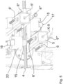
- FIGS 1-5 show the preferred embodiment of the broaching unit 1 according to the present invention, intended to be mounted on a machine for processing metal strips intended to be transformed into rules 4 for die cutters.
- the unit 1 comprises a supporting structure 2, in practice a metal frame or a metal framework, whose task is to support the components of the unit 1.
- One of the components is a guide 3 which defines a sliding surface for a die cutter rule 4.
- the guide 3 thus defines the path along which the rule 4 is intermittently fed, to allow the other components of the unit to perform the broaching.
- the sliding surface is horizontal and thus the rule 4 is oriented with a side facing above, the upper side, and a side facing below, the lower side.
- the means intended for feeding the rule 4 in the guide 3 can be means of the broaching unit 1, for example opposite wheels which rotate on the two sides of the rule 4, or can be means outside of the unit 1, such as in the example shown in the figures.
- the supporting structure 2 comprises two vertical sides 2' and 2" and at least one tool-holding arm 5, preferably two tool-holding arms 5 and 5', as shown in the figures. In general, however, there can also be more than two tool-holding arms, depending on the necessity.
- the tool-holding arms 5 and 5' are mounted on the supporting structure 2 and extend cantileverly from the side 2".
- the reference X-X denotes the longitudinal axis of the arm 5: the arms 5 and 5' can be translated on the relative longitudinal axis X-X in both directions, in response to the thrusts imparted by a first actuator 7 which will now be described with particular reference to figure 2 .
- the arms 5, 5' are supported on the side 2" of the supporting structure 2 and on the guide 3 by means of bearings or bearing brasses.
- the first actuator 7 comprises a first electric motor 9 constrained to the supporting structure 2 and equipped with a pulley 18 coupled to the shaft of the motor 9 itself.
- the pulley 18 in turn actuates another pulley 19 by means of a belt 20.
- the pulley 19 rotates a worm screw 8 along which a carriage, or shuttle, 10 is positioned.
- the carriage 10 engages the worm screw 8 and, in response to the clockwise and counterclockwise rotations of the screw 8, moves towards the side 2" of the supporting structure or away therefrom.
- the tool-holding arms 5 and 5' are translated integrally with the carriage 10, which thus controls the forward and backwards movements along the respective longitudinal axes X-X.
- the first actuator 9 is in common with the two tool-holding arms 5, 5', i.e. it is shared: the translations of the two arms 5, 5' occur synchronously. However, it is possible to achieve a broaching unit 1 with an actuator for each arm 5, 5', so that to make them completely independent.
- the arms 5 and 5' are each provided with at least two broaching units 6, 6'.
- the arms 5, 5' each comprise four broaching tools 6, 6', 6", 6′′′. Only one of the tools 6-6′′′ is active at a given time and interacts with the rule 4 in the guide 3, during the forth and back runs of the relative arm 5, 5', and removes material from the rule 4.
- the broaching tools 6-6′′′ are arranged on the end of the tool-holding arms 5, 5' angularly staggered.
- the angular staggering is of 90°, but can generally be different, depending on the necessity and number of broaching tools present.
- the tools 6-6′′′ are interchangeable, i.e. can be easily separated from the relative arm 5, 5' to be replaced with another tool.
- the unit 1 comprises a second actuator 11 whose task is to rotate the tool-holding arms 5, 5' to change the tool 6-6′′′ which must perform the broaching.
- the second actuator 11 comprises a second electric motor 13 equipped with a pulley.
- a belt 13' transmits the rotations to two pulleys 12', one for each tool-holding arm 5, 5'.
- the pulleys 12 each rotate on the corresponding axis X-X but do not move axially with respect to the side 2" of the supporting structure 2: the arms 5 and 5' are in fact slidable inside the respective pulleys 12 ( fig. 2 ).
- the arm 5 engages the lower side of the rule 4 with the tool 6' and the arm 5' engages the upper side of the rule 4 with the tool 6′′′.
- the second actuator 11 is in common with the two tool-holding arms 5, 5', i.e. it is shared: the translations of the two arms 5, 5' occur in opposite direction.
- the guide 3 is defined in a box-like structure 21, which also houses other components of the unit 1, as will now be described, and through which the arms 5, 5' slide.
- the box-like structure 21 is shown complete in figures 1-2 , and is instead partially disassembled in the remaining figures 3-5 in order to show the other components.
- the box-like structure 21 houses a tracer device 14 for each tool-holding arm 5, 5'.
- the tracer device 14 comprises a foot 15 movable between:
- the foot 15 balances the pressure exerted by the broaching tool 6-6′′′ when it removes material from the rule 4, during the longitudinal movement of the arms 5, 5'. This circumstance is well shown in figure 5 : the foot 15 is in abutment against the upper side of the rule 4, waiting for the tool 6' of the arm 5 to perform the broaching.
- Each of the two tracer devices 14 is actuated by a corresponding actuator 16 or 17: in the example shown, it is a linear guide that extends from the side 2" of the supporting structure 2 to push the foot 15 to the relative active position, and retracts towards the side 2" to allow the return of the foot 15 to the relative inactive position, if necessary thanks to the intervention of a countering elastic element.
- the foot 15 slides in a bushing 22 housed in the box-like structure 21, along a direction orthogonal to the feed direction of the rule 4 in the guide 3.
- the upper part of the foot 15 is rounded and the actuator 16, 17 is in practice a finger with a beveled surface which causes the displacement in the bushing 22, towards the rule 4, by pushing on the foot 15.
- the backwards movement of the actuator 16, 17 allows the foot 15 to return to the inactive position.
- the actuator 16, 17 is equipped with its own motor 23, possibly assisted by an elastic element such as a spring.
- the operations of the unit 1 also describes the method according to the present invention, which provides for the intermittent feeding of a rule 4 on a sliding surface, such as the surface defined by the guide 3, and for the reciprocating forward and backwards movement of the tool-holding arm 5 along a direction transversal to the feed direction of the rule 4.
- the tool-holding arm 5 is provided with at least two selectively activable broaching tools 6-6′′′. By directing the tool-holding arm 5 with respect to the sliding surface, as a result one of the broaching tools 6-6′′′ faces the rule 4 on the sliding surface.
Landscapes
- Engineering & Computer Science (AREA)
- Mechanical Engineering (AREA)
- Automatic Tool Replacement In Machine Tools (AREA)
- Milling, Broaching, Filing, Reaming, And Others (AREA)
- Crushing And Grinding (AREA)
- Perforating, Stamping-Out Or Severing By Means Other Than Cutting (AREA)
- Polishing Bodies And Polishing Tools (AREA)
Claims (15)
- Räumeinheit (1) zum Räumen von Stanzmesserlinien, umfassend eine Trägerstruktur (2), eine Führung (3) für eine Stanzmesserlinie (4) und einen mit einem Räumwerkzeug (6) ausgerüsteten Werkzeughaltearm (5),wobei die Führung (3) eine Gleitfläche der Stanzmesserlinie (4) definiert, undwobei der Werkzeughaltearm (5) an der Trägerstruktur (2) montiert ist und gegenüber dieser und der Gleitfläche hin- und hergehende Bewegungen ausführen kann, um die Stanzmesserlinie (4) mit dem Räumwerkzeug (6) zu erfassen,wobei der Werkzeughaltearm (5) mit mindestens zwei Räumwerkzeugen (6-6",) ausgestattet ist und in Bezug auf die Gleitfläche orientierbar ist, um wahlweise eines der Räumwerkzeuge (6-6‴) zu betätigen, dadurch gekennzeichnet, dass sich der Werkzeughaltearm (5) entlang einer Längsachse (X-X) parallel in Bezug auf die Gleitfläche erstreckt und die Hin- und Herbewegungen entlang einer Querrichtung in Bezug auf die Gleitrichtung der Stanzmesserlinie (4) erfolgen.
- Räumeinheit (1) nach Anspruch 1, wobei der Werkzeughaltearm (5) um die Längsachse (X-X) drehbar ist, um ein einzelnes Räumwerkzeug (6-6‴) zur Gleitfläche der Stanzmesserlinie (4) und somit zu einer Seite der Stanzmesserlinie (4) zu richten.
- Räumeinheit (1) nach Anspruch 2, wobei der Werkzeughaltearm (5) in einer Winkelstellung arretierbar ist, die einem seiner Räumwerkzeuge (6-6‴) entspricht, das der Gleitfläche der Stanzmesserlinie (4) zugewandt ist.
- Räumeinheit (1) nach einem der vorhergehenden Ansprüche, wobei die Räumwerkzeuge (6-6‴) auf dem Werkzeughaltearm (5) austauschbar sind.
- Räumeinheit (1) nach einem der vorhergehenden Ansprüche, umfassend mindestens zwei Werkzeughaltearme (5, 5'), die auf gegenüberliegenden Seiten in Bezug auf die Gleitfläche angeordnet sind, um die Bearbeitung der zwei Seiten der Stanzmesserlinie (4) oder auf derselben Seite zu ermöglichen.
- Räumeinheit (1) nach Anspruch 5, wobei jeder der beiden Werkzeughaltearme (5, 5') unabhängig von den anderen Werkzeughaltearmen (5, 5') oder gemeinsam mit diesen hin- und herbewegbar und/oder orientierbar ist.
- Räumeinheit (1) nach einem der vorhergehenden Ansprüche, wobei die Führung (3) einstückig mit der Trägerstruktur (2) ausgebildet ist und die Werkzeughaltearme (5, 5') sich freitragend von der Trägerstruktur (2) erstrecken und gegenüber dieser zwischen einer vorgezogenen bzw. distalen Position und einer zurückgezogenen bzw. proximalen Position gleiten und eines der Räumwerkzeuge (6-6‴) die Gleitfläche der Stanzmesserlinie (4) zwischen der vorgezogenen und der zurückgezogenen Position schneidet.
- Räumeinheit (1) nach Anspruch 7, umfassend einen ersten Aktuator (7), der von den Werkzeughalterarmen (5, 5') gemeinsam genutzt wird und der den Werkzeughalterarmen (5, 5') zwischen der vorgezogenen und der zurückgezogenen Position hin- und hergehende Bewegungen erteilt, oder alternativ dazu die Räumeinheit (1) einen unabhängigen Aktuator für jeden Werkzeughalterarm (5, 5') umfasst.
- Räumeinheit (1) nach Anspruch 8, wobei der erste Aktuator (7) eine drehbar an der Trägerstruktur (2) montierte Schneckenschraube (8), einen zum Drehen der Schneckenschraube (8) aktivierbaren Motor (9) und einen Wagen oder Shuttle (10), der mit der Schneckenschraube (8) in Eingriff steht und in der Lage ist, sich entlang der Schneckenschraube (8) in beide Richtungen, in Reaktion auf die auf dieselbe Schneckenschraube (8) in beide Richtungen ausgeübten Drehungen zu bewegen, umfasst, und wobei die Werkzeughaltearme (5, 5') mit dem Wagen (10) verfahrfest verbunden sind.
- Räumeinheit (1) nach einem der vorhergehenden Ansprüche, wobei die Führung (3) einstückig mit der Trägerstruktur (2) ausgebildet ist und die Werkzeughalterarme (5, 5') sich freitragend von der Trägerstruktur (2) erstrecken und jeweils um ihre eigene Längsachse (X-X) drehbar sind.
- Räumeinheit (1) nach Anspruch 10, umfassend einen zweiten, von den Werkzeughalterarmen (5, 5') gemeinsam genutzten Aktuator (11), der den Werkzeughalterarmen (5, 5') die Drehungen um die entsprechende Längsachse (X-X) erteilt, oder alternativ die Räumeinheit (1) einen unabhängigen Aktuator für jeden Werkzeughalterarm (5, 5') umfasst.
- Räumeinheit (1) nach Anspruch 11, wobei der zweite Aktuator (11) eine Riemenscheibe oder ein Zahnrad (12), die bzw. das mit jedem Werkzeughaltearm (5, 5') gekoppelt ist, einen Motor (13) und einen Antriebsriemen oder eine Getriebekette (13') umfasst, der bzw. die mit dem Motor (13) und den Riemenscheiben/Zahnrädern (12) verbunden ist, wobei der Motor intermittierende Drehungen erteilt.
- Räumeinheit (1) nach einem der vorhergehenden Ansprüche, umfassend für jeden Werkzeughaltearm (5, 5') eine Tastvorrichtung (14), die vorzugsweise in der Führung (3) untergebracht ist und einen Fuß (15) umfasst, der aus einer aktiven Position, in der er an der in der Führung (3) befindlichen Stanzmesserlinie (4) anliegt, auf der gegenüberliegenden Seite in Bezug auf den entsprechenden Werkzeughaltearm (5, 5') anliegt und die von einem Räumwerkzeug (6-6‴) auf die Räumlinie (4) ausgeübten Kräfte entgegenwirkt, und einer inaktiven Position, in der der Fuß (15) an die Stanzmesserlinie (4) anliegt oder von ihr getrennt ist und den Räumwerkzeug nicht ausgleicht.
- Räumeinheit (1) nach Anspruch 13, umfassend für jede Abtastvorrichtung (14) einen entsprechenden Aktuator (16, 17), vorzugsweise eine lineare Führung, die sich ausdehnt, um den Fuß (15) in die relative aktive Position zu schieben, und sich zurückzieht, um die Rückkehr des Fußes (15) in die relative inaktive Position zu ermöglichen.
- Verfahren zur Durchführung des Räumens einer Linie (4) von Stanzmessern, umfassend:- intermittierendes Zuführen einer Stanzmesserlinie (4) auf einer Gleitfläche;- Hin- und Herbewegen eines Werkzeughaltearms (5, 5') abwechselnd vorwärts und rückwärts entlang einer Querrichtung in Bezug auf die Zuführrichtung der Stanzmesserlinie (4), wobei der Werkzeughaltearm (5, 5') mit zwei oder mehr wahlweise betätigten Räumwerkzeugen (6-6‴) versehen ist;- Richten des Werkzeughaltearms (5, 5') in Bezug auf die Gleitfläche, um eines der Räumwerkzeuge (6-6‴) derart zu betätigen, dass es der Stanzmesserlinie (4) auf der Gleitfläche zugewandt ist, wobei sich der Werkzeughaltearm (5) entlang einer Längsachse (X-X) parallel in Bezug auf die Gleitfläche erstreckt.
Applications Claiming Priority (2)
| Application Number | Priority Date | Filing Date | Title |
|---|---|---|---|
| IT102018000005936A IT201800005936A1 (it) | 2018-06-01 | 2018-06-01 | Unità di brocciatura di lame di fustelle |
| PCT/IB2019/053119 WO2019229552A1 (en) | 2018-06-01 | 2019-04-16 | Unit for broaching rules of die cutters and method to perform the broaching of a rule for die cutters |
Publications (2)
| Publication Number | Publication Date |
|---|---|
| EP3765225A1 EP3765225A1 (de) | 2021-01-20 |
| EP3765225B1 true EP3765225B1 (de) | 2024-07-24 |
Family
ID=63491868
Family Applications (1)
| Application Number | Title | Priority Date | Filing Date |
|---|---|---|---|
| EP19722213.6A Active EP3765225B1 (de) | 2018-06-01 | 2019-04-16 | Vorrichtung zum räumen von richtscheiten von stanzen und verfahren zur durchführung des räumens einer richtscheits für stanzen |
Country Status (4)
| Country | Link |
|---|---|
| US (1) | US11135663B2 (de) |
| EP (1) | EP3765225B1 (de) |
| IT (1) | IT201800005936A1 (de) |
| WO (1) | WO2019229552A1 (de) |
Families Citing this family (2)
| Publication number | Priority date | Publication date | Assignee | Title |
|---|---|---|---|---|
| IT201800005936A1 (it) | 2018-06-01 | 2019-12-01 | Unità di brocciatura di lame di fustelle | |
| CN119328225B (zh) * | 2024-12-23 | 2025-06-17 | 江苏凯慧峰紧固件制造有限公司 | 一种电动工具金属零配件的拉削设备 |
Citations (1)
| Publication number | Priority date | Publication date | Assignee | Title |
|---|---|---|---|---|
| WO2008105040A1 (ja) * | 2007-02-23 | 2008-09-04 | Tomihamaseikou Co., Ltd. | ブローチ刃の支持構造 |
Family Cites Families (9)
| Publication number | Priority date | Publication date | Assignee | Title |
|---|---|---|---|---|
| US2567093A (en) * | 1949-09-12 | 1951-09-04 | American Broach & Machine Co | Broaching machine |
| US2850950A (en) * | 1956-02-02 | 1958-09-09 | Weatherley Oilgear Ltd | Surface broaching machines |
| JPS5854930B2 (ja) * | 1980-10-03 | 1983-12-07 | トヨタ自動車株式会社 | タ−レット.ブロ−チ盤 |
| US5295937A (en) * | 1991-04-25 | 1994-03-22 | Amada Company, Limited | Grooving machine |
| US5533431A (en) * | 1994-08-24 | 1996-07-09 | Schickling; Robert A. | Cutting rule |
| JPH11179614A (ja) * | 1997-10-15 | 1999-07-06 | Komatsu Koki Kk | 複合加工装置及びその加工方法 |
| DE112005003504B4 (de) | 2005-03-14 | 2011-06-09 | Mizukawa, Suehiro, Settsu | Automatische Biegemaschine für einen Bandstahlstanzstempel, sowie Bandstahlstanzstempel |
| DE102011102331A1 (de) * | 2011-05-25 | 2012-11-29 | Dieter Butenuth | Verfahren und Vorrichtung zur Erzeugung von Materialabträgen auf Blechstreifen |
| IT201800005936A1 (it) | 2018-06-01 | 2019-12-01 | Unità di brocciatura di lame di fustelle |
-
2018
- 2018-06-01 IT IT102018000005936A patent/IT201800005936A1/it unknown
-
2019
- 2019-04-16 EP EP19722213.6A patent/EP3765225B1/de active Active
- 2019-04-16 US US17/050,864 patent/US11135663B2/en active Active
- 2019-04-16 WO PCT/IB2019/053119 patent/WO2019229552A1/en not_active Ceased
Patent Citations (1)
| Publication number | Priority date | Publication date | Assignee | Title |
|---|---|---|---|---|
| WO2008105040A1 (ja) * | 2007-02-23 | 2008-09-04 | Tomihamaseikou Co., Ltd. | ブローチ刃の支持構造 |
Also Published As
| Publication number | Publication date |
|---|---|
| WO2019229552A1 (en) | 2019-12-05 |
| US11135663B2 (en) | 2021-10-05 |
| EP3765225A1 (de) | 2021-01-20 |
| IT201800005936A1 (it) | 2019-12-01 |
| US20210229194A1 (en) | 2021-07-29 |
Similar Documents
| Publication | Publication Date | Title |
|---|---|---|
| EP0338015B1 (de) | Verfahren und vorrichtung zum schneiden und entgraten von rohren | |
| CN109586143B (zh) | 剥线机 | |
| EP3765225B1 (de) | Vorrichtung zum räumen von richtscheiten von stanzen und verfahren zur durchführung des räumens einer richtscheits für stanzen | |
| JP2006347170A (ja) | 包装材製造機の変換ステーション | |
| JP4608037B2 (ja) | メタルシートを打ち抜きし及び曲げ加工するためのマシーン | |
| EP2599755B1 (de) | Maschine zum Durchführen von Schneideoperationen auf laminierten Glasplatten | |
| EP0754107A1 (de) | Multidirektionales schneidewerkzeug für schneidpressen | |
| WO2011096361A1 (ja) | ロールカッタ装置 | |
| AU5289393A (en) | Method and machine for producing details from a sheet of metal | |
| ITMI20000083A1 (it) | Macchina automatica per la fenditura e la cordonatura di cartone in fogli e simili | |
| EP3552786B1 (de) | Vorrichtung und verfahren zum bearbeiten eines randes eines werkstückes | |
| EP1507609B1 (de) | Vorrichtung zum schneiden und nibbeln eines bleches in spulenform | |
| WO2005009697A1 (en) | Machine for manufacturing cardboard blanks | |
| EP3463773B1 (de) | Druckweiterverarbeitungsmaschine | |
| EP4065322B1 (de) | System zur positionierung eines werkzeugs auf einer welle und eine bahnschneidevorrichtung, die dieses system zur positionierung eines werkzeugs auf einer welle umfasst | |
| JP3960326B2 (ja) | パンチプレス装置 | |
| JP2000042671A (ja) | ばね成形方法 | |
| US1278857A (en) | Pipe-cutting machine. | |
| CN223936511U (zh) | 一种裁切机 | |
| US10022771B2 (en) | Method for the manufacturing of lamina work pieces | |
| CN221414590U (zh) | 型材开槽设备 | |
| IT202200021276A1 (it) | Apparato di punzonatura di formatura | |
| JP3509974B2 (ja) | 板材加工機 | |
| GB2194778A (en) | Sheet punching and cutting apparatus | |
| CN107662240B (zh) | 一种双排运作的纸张制作装置 |
Legal Events
| Date | Code | Title | Description |
|---|---|---|---|
| STAA | Information on the status of an ep patent application or granted ep patent |
Free format text: STATUS: UNKNOWN |
|
| STAA | Information on the status of an ep patent application or granted ep patent |
Free format text: STATUS: THE INTERNATIONAL PUBLICATION HAS BEEN MADE |
|
| PUAI | Public reference made under article 153(3) epc to a published international application that has entered the european phase |
Free format text: ORIGINAL CODE: 0009012 |
|
| STAA | Information on the status of an ep patent application or granted ep patent |
Free format text: STATUS: REQUEST FOR EXAMINATION WAS MADE |
|
| 17P | Request for examination filed |
Effective date: 20201014 |
|
| AK | Designated contracting states |
Kind code of ref document: A1 Designated state(s): AL AT BE BG CH CY CZ DE DK EE ES FI FR GB GR HR HU IE IS IT LI LT LU LV MC MK MT NL NO PL PT RO RS SE SI SK SM TR |
|
| AX | Request for extension of the european patent |
Extension state: BA ME |
|
| DAV | Request for validation of the european patent (deleted) | ||
| DAX | Request for extension of the european patent (deleted) | ||
| STAA | Information on the status of an ep patent application or granted ep patent |
Free format text: STATUS: EXAMINATION IS IN PROGRESS |
|
| 17Q | First examination report despatched |
Effective date: 20231114 |
|
| GRAP | Despatch of communication of intention to grant a patent |
Free format text: ORIGINAL CODE: EPIDOSNIGR1 |
|
| STAA | Information on the status of an ep patent application or granted ep patent |
Free format text: STATUS: GRANT OF PATENT IS INTENDED |
|
| INTG | Intention to grant announced |
Effective date: 20240405 |
|
| GRAS | Grant fee paid |
Free format text: ORIGINAL CODE: EPIDOSNIGR3 |
|
| GRAA | (expected) grant |
Free format text: ORIGINAL CODE: 0009210 |
|
| STAA | Information on the status of an ep patent application or granted ep patent |
Free format text: STATUS: THE PATENT HAS BEEN GRANTED |
|
| P01 | Opt-out of the competence of the unified patent court (upc) registered |
Free format text: CASE NUMBER: APP_35076/2024 Effective date: 20240611 |
|
| AK | Designated contracting states |
Kind code of ref document: B1 Designated state(s): AL AT BE BG CH CY CZ DE DK EE ES FI FR GB GR HR HU IE IS IT LI LT LU LV MC MK MT NL NO PL PT RO RS SE SI SK SM TR |
|
| REG | Reference to a national code |
Ref country code: GB Ref legal event code: FG4D |
|
| REG | Reference to a national code |
Ref country code: CH Ref legal event code: EP |
|
| REG | Reference to a national code |
Ref country code: IE Ref legal event code: FG4D Ref country code: DE Ref legal event code: R096 Ref document number: 602019055679 Country of ref document: DE |
|
| REG | Reference to a national code |
Ref country code: LT Ref legal event code: MG9D |
|
| REG | Reference to a national code |
Ref country code: NL Ref legal event code: MP Effective date: 20240724 |
|
| PG25 | Lapsed in a contracting state [announced via postgrant information from national office to epo] |
Ref country code: PT Free format text: LAPSE BECAUSE OF FAILURE TO SUBMIT A TRANSLATION OF THE DESCRIPTION OR TO PAY THE FEE WITHIN THE PRESCRIBED TIME-LIMIT Effective date: 20241125 |
|
| REG | Reference to a national code |
Ref country code: AT Ref legal event code: MK05 Ref document number: 1705870 Country of ref document: AT Kind code of ref document: T Effective date: 20240724 |
|
| PG25 | Lapsed in a contracting state [announced via postgrant information from national office to epo] |
Ref country code: NL Free format text: LAPSE BECAUSE OF FAILURE TO SUBMIT A TRANSLATION OF THE DESCRIPTION OR TO PAY THE FEE WITHIN THE PRESCRIBED TIME-LIMIT Effective date: 20240724 |
|
| PG25 | Lapsed in a contracting state [announced via postgrant information from national office to epo] |
Ref country code: PT Free format text: LAPSE BECAUSE OF FAILURE TO SUBMIT A TRANSLATION OF THE DESCRIPTION OR TO PAY THE FEE WITHIN THE PRESCRIBED TIME-LIMIT Effective date: 20241125 Ref country code: NL Free format text: LAPSE BECAUSE OF FAILURE TO SUBMIT A TRANSLATION OF THE DESCRIPTION OR TO PAY THE FEE WITHIN THE PRESCRIBED TIME-LIMIT Effective date: 20240724 |
|
| PG25 | Lapsed in a contracting state [announced via postgrant information from national office to epo] |
Ref country code: NO Free format text: LAPSE BECAUSE OF FAILURE TO SUBMIT A TRANSLATION OF THE DESCRIPTION OR TO PAY THE FEE WITHIN THE PRESCRIBED TIME-LIMIT Effective date: 20241024 |
|
| PG25 | Lapsed in a contracting state [announced via postgrant information from national office to epo] |
Ref country code: GR Free format text: LAPSE BECAUSE OF FAILURE TO SUBMIT A TRANSLATION OF THE DESCRIPTION OR TO PAY THE FEE WITHIN THE PRESCRIBED TIME-LIMIT Effective date: 20241025 Ref country code: PL Free format text: LAPSE BECAUSE OF FAILURE TO SUBMIT A TRANSLATION OF THE DESCRIPTION OR TO PAY THE FEE WITHIN THE PRESCRIBED TIME-LIMIT Effective date: 20240724 Ref country code: FI Free format text: LAPSE BECAUSE OF FAILURE TO SUBMIT A TRANSLATION OF THE DESCRIPTION OR TO PAY THE FEE WITHIN THE PRESCRIBED TIME-LIMIT Effective date: 20240724 |
|
| PG25 | Lapsed in a contracting state [announced via postgrant information from national office to epo] |
Ref country code: BG Free format text: LAPSE BECAUSE OF FAILURE TO SUBMIT A TRANSLATION OF THE DESCRIPTION OR TO PAY THE FEE WITHIN THE PRESCRIBED TIME-LIMIT Effective date: 20240724 |
|
| PG25 | Lapsed in a contracting state [announced via postgrant information from national office to epo] |
Ref country code: LV Free format text: LAPSE BECAUSE OF FAILURE TO SUBMIT A TRANSLATION OF THE DESCRIPTION OR TO PAY THE FEE WITHIN THE PRESCRIBED TIME-LIMIT Effective date: 20240724 |
|
| PG25 | Lapsed in a contracting state [announced via postgrant information from national office to epo] |
Ref country code: IS Free format text: LAPSE BECAUSE OF FAILURE TO SUBMIT A TRANSLATION OF THE DESCRIPTION OR TO PAY THE FEE WITHIN THE PRESCRIBED TIME-LIMIT Effective date: 20241124 Ref country code: AT Free format text: LAPSE BECAUSE OF FAILURE TO SUBMIT A TRANSLATION OF THE DESCRIPTION OR TO PAY THE FEE WITHIN THE PRESCRIBED TIME-LIMIT Effective date: 20240724 |
|
| PG25 | Lapsed in a contracting state [announced via postgrant information from national office to epo] |
Ref country code: HR Free format text: LAPSE BECAUSE OF FAILURE TO SUBMIT A TRANSLATION OF THE DESCRIPTION OR TO PAY THE FEE WITHIN THE PRESCRIBED TIME-LIMIT Effective date: 20240724 |
|
| PG25 | Lapsed in a contracting state [announced via postgrant information from national office to epo] |
Ref country code: ES Free format text: LAPSE BECAUSE OF FAILURE TO SUBMIT A TRANSLATION OF THE DESCRIPTION OR TO PAY THE FEE WITHIN THE PRESCRIBED TIME-LIMIT Effective date: 20240724 |
|
| PG25 | Lapsed in a contracting state [announced via postgrant information from national office to epo] |
Ref country code: PL Free format text: LAPSE BECAUSE OF FAILURE TO SUBMIT A TRANSLATION OF THE DESCRIPTION OR TO PAY THE FEE WITHIN THE PRESCRIBED TIME-LIMIT Effective date: 20240724 Ref country code: NO Free format text: LAPSE BECAUSE OF FAILURE TO SUBMIT A TRANSLATION OF THE DESCRIPTION OR TO PAY THE FEE WITHIN THE PRESCRIBED TIME-LIMIT Effective date: 20241024 Ref country code: LV Free format text: LAPSE BECAUSE OF FAILURE TO SUBMIT A TRANSLATION OF THE DESCRIPTION OR TO PAY THE FEE WITHIN THE PRESCRIBED TIME-LIMIT Effective date: 20240724 Ref country code: IS Free format text: LAPSE BECAUSE OF FAILURE TO SUBMIT A TRANSLATION OF THE DESCRIPTION OR TO PAY THE FEE WITHIN THE PRESCRIBED TIME-LIMIT Effective date: 20241124 Ref country code: HR Free format text: LAPSE BECAUSE OF FAILURE TO SUBMIT A TRANSLATION OF THE DESCRIPTION OR TO PAY THE FEE WITHIN THE PRESCRIBED TIME-LIMIT Effective date: 20240724 Ref country code: GR Free format text: LAPSE BECAUSE OF FAILURE TO SUBMIT A TRANSLATION OF THE DESCRIPTION OR TO PAY THE FEE WITHIN THE PRESCRIBED TIME-LIMIT Effective date: 20241025 Ref country code: FI Free format text: LAPSE BECAUSE OF FAILURE TO SUBMIT A TRANSLATION OF THE DESCRIPTION OR TO PAY THE FEE WITHIN THE PRESCRIBED TIME-LIMIT Effective date: 20240724 Ref country code: ES Free format text: LAPSE BECAUSE OF FAILURE TO SUBMIT A TRANSLATION OF THE DESCRIPTION OR TO PAY THE FEE WITHIN THE PRESCRIBED TIME-LIMIT Effective date: 20240724 Ref country code: BG Free format text: LAPSE BECAUSE OF FAILURE TO SUBMIT A TRANSLATION OF THE DESCRIPTION OR TO PAY THE FEE WITHIN THE PRESCRIBED TIME-LIMIT Effective date: 20240724 Ref country code: AT Free format text: LAPSE BECAUSE OF FAILURE TO SUBMIT A TRANSLATION OF THE DESCRIPTION OR TO PAY THE FEE WITHIN THE PRESCRIBED TIME-LIMIT Effective date: 20240724 |
|
| PG25 | Lapsed in a contracting state [announced via postgrant information from national office to epo] |
Ref country code: SM Free format text: LAPSE BECAUSE OF FAILURE TO SUBMIT A TRANSLATION OF THE DESCRIPTION OR TO PAY THE FEE WITHIN THE PRESCRIBED TIME-LIMIT Effective date: 20240724 Ref country code: DK Free format text: LAPSE BECAUSE OF FAILURE TO SUBMIT A TRANSLATION OF THE DESCRIPTION OR TO PAY THE FEE WITHIN THE PRESCRIBED TIME-LIMIT Effective date: 20240724 Ref country code: RO Free format text: LAPSE BECAUSE OF FAILURE TO SUBMIT A TRANSLATION OF THE DESCRIPTION OR TO PAY THE FEE WITHIN THE PRESCRIBED TIME-LIMIT Effective date: 20240724 |
|
| PG25 | Lapsed in a contracting state [announced via postgrant information from national office to epo] |
Ref country code: EE Free format text: LAPSE BECAUSE OF FAILURE TO SUBMIT A TRANSLATION OF THE DESCRIPTION OR TO PAY THE FEE WITHIN THE PRESCRIBED TIME-LIMIT Effective date: 20240724 |
|
| PG25 | Lapsed in a contracting state [announced via postgrant information from national office to epo] |
Ref country code: CZ Free format text: LAPSE BECAUSE OF FAILURE TO SUBMIT A TRANSLATION OF THE DESCRIPTION OR TO PAY THE FEE WITHIN THE PRESCRIBED TIME-LIMIT Effective date: 20240724 |
|
| REG | Reference to a national code |
Ref country code: DE Ref legal event code: R097 Ref document number: 602019055679 Country of ref document: DE |
|
| PG25 | Lapsed in a contracting state [announced via postgrant information from national office to epo] |
Ref country code: SK Free format text: LAPSE BECAUSE OF FAILURE TO SUBMIT A TRANSLATION OF THE DESCRIPTION OR TO PAY THE FEE WITHIN THE PRESCRIBED TIME-LIMIT Effective date: 20240724 |
|
| PLBE | No opposition filed within time limit |
Free format text: ORIGINAL CODE: 0009261 |
|
| STAA | Information on the status of an ep patent application or granted ep patent |
Free format text: STATUS: NO OPPOSITION FILED WITHIN TIME LIMIT |
|
| 26N | No opposition filed |
Effective date: 20250425 |
|
| PGFP | Annual fee paid to national office [announced via postgrant information from national office to epo] |
Ref country code: DE Payment date: 20250317 Year of fee payment: 7 |
|
| PGFP | Annual fee paid to national office [announced via postgrant information from national office to epo] |
Ref country code: IT Payment date: 20250402 Year of fee payment: 7 |
|
| PG25 | Lapsed in a contracting state [announced via postgrant information from national office to epo] |
Ref country code: SE Free format text: LAPSE BECAUSE OF FAILURE TO SUBMIT A TRANSLATION OF THE DESCRIPTION OR TO PAY THE FEE WITHIN THE PRESCRIBED TIME-LIMIT Effective date: 20240724 |
|
| REG | Reference to a national code |
Ref country code: CH Ref legal event code: H13 Free format text: ST27 STATUS EVENT CODE: U-0-0-H10-H13 (AS PROVIDED BY THE NATIONAL OFFICE) Effective date: 20251125 |
|
| PG25 | Lapsed in a contracting state [announced via postgrant information from national office to epo] |
Ref country code: LU Free format text: LAPSE BECAUSE OF NON-PAYMENT OF DUE FEES Effective date: 20250416 |
|
| PG25 | Lapsed in a contracting state [announced via postgrant information from national office to epo] |
Ref country code: MC Free format text: LAPSE BECAUSE OF FAILURE TO SUBMIT A TRANSLATION OF THE DESCRIPTION OR TO PAY THE FEE WITHIN THE PRESCRIBED TIME-LIMIT Effective date: 20240724 |
|
| REG | Reference to a national code |
Ref country code: BE Ref legal event code: MM Effective date: 20250430 |
|
| PG25 | Lapsed in a contracting state [announced via postgrant information from national office to epo] |
Ref country code: BE Free format text: LAPSE BECAUSE OF NON-PAYMENT OF DUE FEES Effective date: 20250430 |
|
| PG25 | Lapsed in a contracting state [announced via postgrant information from national office to epo] |
Ref country code: CH Free format text: LAPSE BECAUSE OF NON-PAYMENT OF DUE FEES Effective date: 20250430 |
|
| PGFP | Annual fee paid to national office [announced via postgrant information from national office to epo] |
Ref country code: GB Payment date: 20260320 Year of fee payment: 8 |
|
| PG25 | Lapsed in a contracting state [announced via postgrant information from national office to epo] |
Ref country code: IE Free format text: LAPSE BECAUSE OF NON-PAYMENT OF DUE FEES Effective date: 20250416 |
|
| PGFP | Annual fee paid to national office [announced via postgrant information from national office to epo] |
Ref country code: FR Payment date: 20260317 Year of fee payment: 8 |