EP3763265A1 - Tragbares sauggerät - Google Patents
Tragbares sauggerät Download PDFInfo
- Publication number
- EP3763265A1 EP3763265A1 EP19186088.1A EP19186088A EP3763265A1 EP 3763265 A1 EP3763265 A1 EP 3763265A1 EP 19186088 A EP19186088 A EP 19186088A EP 3763265 A1 EP3763265 A1 EP 3763265A1
- Authority
- EP
- European Patent Office
- Prior art keywords
- suction
- intermediate element
- suction device
- receiving area
- electric motor
- Prior art date
- Legal status (The legal status is an assumption and is not a legal conclusion. Google has not performed a legal analysis and makes no representation as to the accuracy of the status listed.)
- Granted
Links
Images


Classifications
-
- A—HUMAN NECESSITIES
- A47—FURNITURE; DOMESTIC ARTICLES OR APPLIANCES; COFFEE MILLS; SPICE MILLS; SUCTION CLEANERS IN GENERAL
- A47L—DOMESTIC WASHING OR CLEANING; SUCTION CLEANERS IN GENERAL
- A47L9/00—Details or accessories of suction cleaners, e.g. mechanical means for controlling the suction or for effecting pulsating action; Storing devices specially adapted to suction cleaners or parts thereof; Carrying-vehicles specially adapted for suction cleaners
- A47L9/22—Mountings for motor fan assemblies
-
- A—HUMAN NECESSITIES
- A47—FURNITURE; DOMESTIC ARTICLES OR APPLIANCES; COFFEE MILLS; SPICE MILLS; SUCTION CLEANERS IN GENERAL
- A47L—DOMESTIC WASHING OR CLEANING; SUCTION CLEANERS IN GENERAL
- A47L1/00—Cleaning windows
- A47L1/02—Power-driven machines or devices
- A47L1/05—Hand apparatus with built-in electric motors
-
- A—HUMAN NECESSITIES
- A47—FURNITURE; DOMESTIC ARTICLES OR APPLIANCES; COFFEE MILLS; SPICE MILLS; SUCTION CLEANERS IN GENERAL
- A47L—DOMESTIC WASHING OR CLEANING; SUCTION CLEANERS IN GENERAL
- A47L7/00—Suction cleaners adapted for additional purposes; Tables with suction openings for cleaning purposes; Containers for cleaning articles by suction; Suction cleaners adapted to cleaning of brushes; Suction cleaners adapted to taking-up liquids
- A47L7/0004—Suction cleaners adapted to take up liquids, e.g. wet or dry vacuum cleaners
- A47L7/0023—Recovery tanks
-
- A—HUMAN NECESSITIES
- A47—FURNITURE; DOMESTIC ARTICLES OR APPLIANCES; COFFEE MILLS; SPICE MILLS; SUCTION CLEANERS IN GENERAL
- A47L—DOMESTIC WASHING OR CLEANING; SUCTION CLEANERS IN GENERAL
- A47L7/00—Suction cleaners adapted for additional purposes; Tables with suction openings for cleaning purposes; Containers for cleaning articles by suction; Suction cleaners adapted to cleaning of brushes; Suction cleaners adapted to taking-up liquids
- A47L7/0004—Suction cleaners adapted to take up liquids, e.g. wet or dry vacuum cleaners
- A47L7/0042—Gaskets; Sealing means
-
- A—HUMAN NECESSITIES
- A47—FURNITURE; DOMESTIC ARTICLES OR APPLIANCES; COFFEE MILLS; SPICE MILLS; SUCTION CLEANERS IN GENERAL
- A47L—DOMESTIC WASHING OR CLEANING; SUCTION CLEANERS IN GENERAL
- A47L9/00—Details or accessories of suction cleaners, e.g. mechanical means for controlling the suction or for effecting pulsating action; Storing devices specially adapted to suction cleaners or parts thereof; Carrying-vehicles specially adapted for suction cleaners
- A47L9/0081—Means for exhaust-air diffusion; Means for sound or vibration damping
Definitions
- the invention relates to a portable suction device according to the preamble of claim 1.
- the invention relates to a portable suction device with a suction channel opening into a suction nozzle and with a housing, a suction material container and a suction unit having at least one electric motor, an accumulator and a fan wheel for generating a suction flow, which provides a suction vacuum applied to the suction nozzle, and with a separation device, which is able to split the suction flow sucked in via the suction nozzle into an exhaust air flow flowing out of the suction device and into suction material in the form of particles and / or fluid components, the separated particles or Fluid components are collected in the suction material container.
- these devices also have a pull-off lip for pulling off liquids, the pull-off lip being arranged on the suction nozzle.
- these devices are usually battery-operated and are held in the hand of a user while the user guides the pull-off lip along the surface to be vacuumed.
- Portable devices of this type are among others from EP 2 845 530 B1 known.
- the known suction devices are used to suck up a liquid / air mixture. As in the case of the device mentioned, this can be done for sucking up liquid, for example from a flat surface such as a table top, window panes or tiles.
- a pull-off lip arranged on the suction nozzle is provided in the generic devices for residue-free cleaning of the surfaces.
- a portable suction device described which provides a separate waterproof unit that includes the electric motor, the accumulator and the component electronics.
- the separate unit is built into the housing of the suction device.
- the encapsulation leads to increased heating of the components, in particular of the electric motor, but also of the temperature-sensitive accumulator. This results from the multi-layer structure, which accordingly causes undesirable insulation with poor heat dissipation.
- the increased heating can reduce the service life of the components.
- the usage time can also be shortened if the device has to be switched off due to excess temperature.
- the object of the invention is therefore to provide a portable suction device which enables the electronic components to be sealed against ingress of suction material while at the same time providing good heat dissipation and cost-effective production.
- the portable suction device provides that part of the suction material container limitation has a receiving area for receiving electronic components of the suction device, the receiving area being in the form of at least one cavity that is watertight except for the opening and being watertightly closable by a separate intermediate element.
- the electronic components include at least the electric motor and the accumulator, but can also include further electronic components, such as monitoring and / or control elements arranged on a circuit board.
- the cavity can consist of one or more pockets, the individual electronic components being arranged in the pockets.
- the electronic components are protected against the ingress of dust and water by the watertight, sealed cavity in the suction cup delimitation. Furthermore, the arrangement does not have any heat-insulating encapsulation of the components, so that the heat lost during operation of the device can be dissipated well. This can be done directly via the housing to the environment and also to the suctioned material.
- the intermediate element preferably forms a component carrier by which at least the electric motor and the accumulator are held.
- the fan wheel is advantageously arranged, rotatably mounted on the intermediate element on the side of the intermediate element facing away from the receiving area.
- the construction according to the invention is advantageous in terms of production and thus in terms of costs, since a preassembled module is formed with the aid of the intermediate element, which can be used as a whole in one assembly step.
- the intermediate element can in this case preferably be designed geometrically in the form of component receiving elements in such a way as to receive at least the electric motor and / or the accumulator in a defined manner.
- Individual pockets or receptacles or ribs can be provided in the intermediate element.
- the electronic components are inserted and held in these. It is advantageous if, for example, the electric motor and the accumulator and any circuit board with measuring and control elements are arranged in separate pockets.
- the electronic components are at least partially isolated from one another by the walls of the pockets, so that the waste heat from the electric motor does not additionally heat the accumulator or the circuit board.
- the pockets are preferably designed in such a way that, on the one hand, good heat dissipation of the components and thermal insulation between the electronic components is achieved. On the other hand, in such a way that the electronic components are securely held in the pockets. This can be implemented, for example, by pockets with walls of different heights and / or recesses within the pockets.
- soft elements can be arranged on the intermediate element and / or in the receiving area, the electronic components, in particular the electric motor and / or the accumulator, which is arranged softly supported in the intermediate element. This is advantageous when the intermediate element is constructed with a plurality of pockets in which the individual electronic components are received.
- the soft elements are arranged and designed in such a way that the electronic components are held by the intermediate element without play.
- the soft tissue storage also functions in an advantageous manner as a damper for the electronic components if the device is put down rudely or if it is accidentally dropped.
- means are provided which are set up to improve the heat dissipation of the electronic components.
- the means can be formed by heat-conducting areas in the area of the intermediate element and / or in the area of the receiving area.
- the thermally conductive areas can be constructed in the form of ribs or similar designs and / or be achieved by a thermally conductive material combination.
- the heat-conducting areas can be formed by encapsulated metal.
- the intermediate element and the component receiving elements of the intermediate element, which receive the electronic components, are preferably formed from plastic.
- thermally conductive particles can be added to the plastic, for example copper particles.
- the geometry of the suction device is designed such that the heat dissipation in the direction of the suction material container or suction material is higher than in the other directions.
- This can be implemented, for example, in that at least part of the receiving area in the suction material container delimitation is part of the suction device housing and / or is arranged close to the suction device housing.
- the intermediate element advantageously has a circumferential sealing contour as a sealing element.
- the cavity formed by the suction material container limitation The receiving area can have a one-sided and flat opening.
- the circumferential sealing contour of the intermediate element can be designed to be flat.
- geometrical configurations that correspond to one another are provided on the housing and / or on the receiving area and on the intermediate element. These are designed such that the intermediate element is held in at least one direction and can close the receiving area.
- the intermediate element is preferably made as a two-component component from a hard plastic and a soft plastic forming the soft elements.
- the seal of the intermediate element can also be injection molded.
- the fan wheel is arranged on the side of the intermediate element facing away from the receiving area and is driven by the electric motor.
- the intermediate element has a passage opening for the motor shaft.
- a motor shaft seal is provided to seal the motor shaft.
- the motor shaft seal can be molded on and / or mounted as a separate part on the intermediate element.
- a switching element for switching on the suction device can be provided as electronic components, which is preferably arranged on a measuring and / or control board.
- an elastic housing area can advantageously be provided above the switch, via which the switch can be actuated.
- the housing is preferably designed to be translucent in one area.
- An LED can be provided below the translucent area, which indicates operation of the suction device. This has the advantage that there is no need to provide a separate cutout for the LED in the housing.
- the configuration enables a particularly attractive design.
- the LED can be arranged on the circuit board, for example.
- the shape of the suction device is designed so that the suction device extends into a handle of the suction device on the end section opposite the suction nozzle.
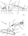
- the suction device 2 is shown in a side view.
- the suction device 2 is designed as a hand-operated window vacuum.
- the suction device 2 comprises in the front area a suction nozzle 4 designed as a flat nozzle with pulling lips 5 arranged above and below the flat nozzle opening, which is detachably arranged via a clamp connection on a beak-shaped receptacle 62 formed from two parallel planes.
- the suction device 2 has a suction and separation area adjoining the suction nozzle 4, a suction unit 10, a suction material container 8 and a closure 42.
- the aforementioned components are accommodated in a housing 6 of the suction device 2.
- the suction device 2 is initially shaped like a bulb in the area of the separation area and the suction unit 10 and then extends into a rear area which forms a handle 48.
- the handle 48 closes with the lock 42 at the distal end.
- the suction material container 8 is largely located in the handle 48 and extends to the end of the handle 48.
- an opening 40 is provided in the suction material container 8, which is sealed by the closure 42 against the escape of suction material, in particular water is.
- the housing 6 of the suction device 2 is constructed in several parts. It comprises an upper shell 64, which ventilation slots 66 for the exhaust air flow and a recess for a Has actuating button 68 for switching the device 2 on and off.
- the upper shell 64 of the housing 6 is placed on a lower part of the housing.
- the lower part of the housing forms part of the handle 48 as a handle shell 70, the handle 48 being made in several parts.
- the handle shell 70 in turn simultaneously forms a lower boundary of the suction material container 8.
- the suction and separation areas are each received by a front part of the housing 6, which also forms the receptacle for the suction nozzle 62.
- the shape of the suction device 2 is designed in such a way that the device 2, when it is placed on a flat storage surface 72, is accommodated by two storage areas.
- the first storage area is formed by the lower part of the handle shell 70, on which two feet are provided as storage elements 74.
- the two storage elements 74 are arranged on both sides at a distance from a longitudinal axis of the suction device 2.
- a part of the lock 42 forms the second storage area.
- the two storage elements 74 allow the suction device 2 to be placed on the flat storage surface 72 in a stable manner.
- the storage areas are arranged on the suction device 2 in such a way that the suction nozzle 4 and in particular the pull-off lip 5 are spaced apart from the flat storage surface 72.
- Both the outer area of the closure 42 and the storage elements 74 designed as feet are made from a soft material, in particular from a rubber-like material. In this way, in addition to a stable and surface-friendly state of the device 2 when the device 2 is switched off, damage when using the device 2, if the device 2 does not come into contact with the surface to be cleaned or the surfaces around it, is avoided.
- FIG. 4 shows a perspective view of the suction device 2 from FIG Figure 1 .
- the upper part of the receptacle of the suction nozzle 62 can be seen, in which the suction nozzle 4, which is designed as a flat nozzle, is detachably inserted via the clamp connection. Due to the releasable connection, other suction nozzles can also be used in the intake of the suction nozzle, depending on the area of application.
- the closure 42 continuing the outer contour of the device 2 is shown spaced apart from the suction device 2 in the dismantled state.
- the closure 42 has a gripping area at the end, which is formed by a raised edge in the form of a retaining bead 76 in the rear area.
- FIG. 3 shows another view of the suction device 2 according to the invention from the previous figures.
- the suction device 2 is shown with a cut-free separation area and without an upper housing shell 64 and without a closure 42.
- the suction material sucked in by the suction nozzle 4, not shown, is transferred into the separation area via a suction channel 3 arranged in the receptacle for the suction nozzle 62, and separated from the exhaust air flow by the separation device 12 and transferred into an inlet opening 36 arranged in the lower part of the suction device 2.
- the inlet opening 36 leads into the suction material guide 30, via which the suction material is in turn directed into the suction material container 8.
- the individual components of the separation device 12 can be seen in the cut-free area, which comprises a ramp-shaped suction material guide element 14 and a rotary separator 16.
- the rotary separator 16 is connected in one piece to the fan wheel 11 of the suction unit 10.
- the separation area is designed as a separation chamber 18.
- the delimitation forming the separation chamber 18 is designed in two parts.
- the first part is formed by a cup-shaped first delimiting element 92, in the bottom area of which the beak-shaped receptacle for the suction nozzle 62 is also formed.
- the cup-shaped delimiting element 92 is at the same time also part of the suction device housing 6.
- the second part of the separation chamber delimitation is formed by a cover element 94, which is formed as a plate-shaped delimiting element and is connected to the cup-shaped delimiting element 92.
- the cover element 94 has two openings.
- the rotary separator 16 which is integrally connected to the fan wheel 11, is arranged in the first opening, which is arranged centrally in the cover element and is an exhaust air opening.
- the second opening is an outlet opening of the separation chamber 18 and is at the same time the inlet opening 36 into the suction material guide 30.
- a cover element 27 of the suction material container 8 with the suction unit 10 mounted is shown in a side view.
- the cover element 27 is detachably connected to the grip shell 70 by a clamp connection during assembly.
- a receiving area 22 is provided for receiving the electronic components of the suction unit 10, in particular an electric motor 24, a circuit board 25 and an accumulator 26, the receiving area 22 being in the form of a pocket-shaped cavity.
- the receiving area 22, which is designed as a cavity open on one side, is designed in one piece in the housing cover 27.
- the accumulator 26 and in are in a geometrically longer pocket an underlying geometrically shorter pocket of the electric motor 24 was added.
- the receiving area 22 is designed in a step-like manner in accordance with the shape of electronic components.
- the receiving area 22 is sealed by a separate intermediate element 23 against the escape of suction material, the intermediate element 23 simultaneously functioning as a component carrier for the electric motor 24, the circuit board 25 and the accumulator 26.
- Component receiving elements 28 for the electrical components are provided in the intermediate element 23.
- the component receiving elements 28 are designed as holders in the form of hollow beams.
- the intermediate element 23 is supported both by the grip shell 70 and by the cover element 27.
- centering openings 29 are distributed circumferentially in the radially outer region of the intermediate element 23.
- the cover element 27 with the receiving area 22 is shown in a view obliquely from the front in FIG Figure 5 shown.
- the receiving area 22 embodied as a hollow body has, on the side of the receiving area 22 facing the suction nozzle 4, a rectangular cross section with a rounded top and bottom.
- the rectangular cross-section is provided to accommodate the electric motor 24, the accumulator 26 and the circuit board 25 together with their respective holders.
- the geometrically longer pocket for the accumulator 26 is provided in the part of the receiving area 22 directed towards the upper side of the suction device 2, this being of essentially round cross-section, corresponding to the cross-section of the accumulator 26.
- a seat for a motor shaft bearing 87 of the electric motor 24 is provided in the part of the receiving area 22 that receives the electric motor 24, a seat for a motor shaft bearing 87 of the electric motor 24 is provided.
- This receptacle for the motor shaft bearing 87 is arranged concentrically with the electric motor 24 and with the fan wheel 11 driven by the latter.
- a bulge 89 is provided directly next to the receptacle for the motor shaft bearing 87. This acts as a clearance for a soldering lug and a motor cable of the electric motor.
- a recess is also provided in the shell component in a shell component 32 which is arranged below the receiving area 22 and forms part of the suction material guide 30.
- the recess and bulge 89 are matched to one another in such a way that the receiving area 22 and the shell component 32 do not touch at this point.
- a cable opening 88 is provided in the direction of the suction material guide 30, through which the cables for a charging connection on the underside of the suction device 2 when the suction device 2 is installed.
- a sealing element is provided on the underside of the receiving area 22, which seals the cable opening 88 in the receiving area 22 against the entry of suction material.
- the sealing element is designed as a circumferential seal and interacts with a corresponding sealing groove on the shell component 32.
- a part of the cover element 27, which is arranged above the actuating button 68 on the circuit board 25 when the suction device 2 is mounted, is formed as an elastic housing area.
- the actuation button 68 can be actuated in the assembled state through the elastic housing area for switching the suction device 2 on and off by a pressure load.
- the elastic housing area is formed from a soft material, in particular a rubber-like material.
- part of the elastic housing area is made translucent. Furthermore, an LED is provided below the translucent area of the housing, which indicates an operating state of the suction device 2.
- the grip shell 70 forms the bulbous part of the suction device 2 up to the end of the receiving area 22 pointing towards the closure 42 and from there merges into the handle 48. In this way, a particularly advantageous use of installation space is achieved.
- FIGS Figures 6 and 7th A perspective front and rear view of the intermediate element 23 designed as a component carrier are shown in FIGS Figures 6 and 7th .
- the intermediate element 23 has four centering openings 29 which are arranged symmetrically distributed over the intermediate element 23.
- the upper part of the intermediate element 23 has a half-shell reinforced by ribs, which extends in the direction of the rotary separator 16.
- the height of the half-shell is designed in such a way that it lies above the height of the radially outer region of the fan blades of the fan wheel 11. In the illustrated embodiment extends the half-shell is between two centering openings, the top two. In this way, better support between the centering or positioning elements 90 of the cover element 27 and the centering openings 29 of the intermediate element 23 is achieved.
- the provision of the half-shell serves to discharge the exhaust air flow in a directed manner out of the suction device 2, in particular over the sides of the suction device 2.
- a cover element designed as a plate-shaped delimitation element of the separation area is placed on the intermediate element 23 in the direction of the rotary separator and closes the area of the half-shell.
- the two lower centering openings 29 of the intermediate element 23 are positioned in the assembled state of the device on both sides of the semicircular inlet opening 36 in the suction material guide 30.
- the cover element 94 is sealingly placed on the inlet opening 36 in the suction material guide 30. Due to the laterally open areas formed between the intermediate element 23 and the cover element 94, the exhaust air flow is guided out of the suction device 2 through the ventilation slots 66 in the upper housing cover 64.
- a sealing element 58 designed as a circumferential seal is provided, the sealing element 58 being rectangular, corresponding to the rectangular opening of the receiving area 22, such that the intermediate element 23 seals the receiving area 22 against ingress of suction material able.
- the seal is injection molded onto the intermediate element 23 and forms a flat sealing contour.
- the component receiving elements 28 in which the electric motor 24, the accumulator 26 and the circuit board 25 are held are provided spatially within the circumferential seal on the intermediate element 23.
- the component receiving elements 28 are integrally connected to the intermediate element 23.
- the component receiving elements 28 do not completely enclose the electronic components in order to enable good heat dissipation, but also good support for the components.
- a housing of the electric motor 24 has a rectangular cross section.
- the component receiving element 28 holding the electric motor 24 holds the electric motor 24 only on the housing covers, the part of the housing of the electric motor 24 facing away from the intermediate element 23 being covered less by the component receiving element 28 than the part facing the intermediate element 23. In this way, good heat dissipation is achieved and the resulting waste heat in the direction of suction material guide 30 or suction material container 8 headed.
- the temperature-sensitive accumulator 26 is at least partially shielded from the waste heat from the electric motor 24.
- a complete, more solid enclosure of the electric motor 24 by the component receiving element 28 can be dispensed with, since the electric motor 24 is mounted for low-vibration operation of the fan wheel 11 via the motor shaft bearing 86, which is received in the receptacle for the motor shaft bearing 87 in the receiving area 22.
- inserted soft elements are provided which are set up in such a way that the electronic components, in particular the electric motor 24 and the accumulator 26, are securely seated. Furthermore, soft elements are also provided on the outside of the component receiving elements 28 in order to also hold the component receiving elements 28 securely in the receiving area 22.
Landscapes
- Engineering & Computer Science (AREA)
- Mechanical Engineering (AREA)
- Manipulator (AREA)
Abstract
Description
- Die Erfindung betrifft ein tragbares Sauggerät nach dem Oberbegriff des Anspruchs 1. Insbesondere betrifft die Erfindung ein tragbares Sauggerät mit einem in eine Saugdüse mündenden Saugkanal und mit einem Gehäuse, einem Sauggutbehälter und einem zumindest einen Elektromotor, einen Akkumulator, und ein Lüfterrad aufweisendes Saugaggregat zur Erzeugung einer Saugströmung, die einen an der Saugdüse anliegenden Saugunterdruck bereitstellt, und mit einer Abscheideeinrichtung, die die über die Saugdüse angesaugte Saugströmung in eine aus dem Sauggerät strömende Abluftströmung und in Sauggut in Form von Partikeln und/oder Fluidbestandteilen aufzuteilen vermag, wobei die abgeschiedenen Partikel oder Fluidbestandteile in dem Sauggutbehälter gesammelt sind. Insbesondere weisen diese Geräte auch eine Abziehlippe zum Abziehen von Flüssigkeiten auf, wobei die Abziehlippe an der Saugdüse angeordnet ist. Zudem sind diese Geräte üblicherweise batteriebetrieben und werden in der Hand eines Benutzers gehalten, während dieser die Abziehlippe entlang der abzusaugenden Fläche führt.
- Tragbare Geräte dieser Art sind unter anderem aus der
EP 2 845 530 B1 bekannt. Die bekannten Sauggeräte werden verwendet, um ein Flüssigkeit-/Luftgemisch aufzusaugen. Dies kann, wie im Fall der genannten Vorrichtung, zum Aufsaugen von Flüssigkeit, zum Beispiel von einer ebenen Oberfläche wie einer Tischplatte, von Fensterscheiben oder Fliesen erfolgen. Zum rückständefreien Reinigen der Oberflächen ist bei den gattungsgemäßen Geräten eine an der Saugdüse angeordnete Abziehlippe vorgesehen. - Durch die vielfältigen Einsatzmöglichkeiten dieser Geräte werden diese in verschiedenen Orientierungen verwendet. Dies reicht von einem normalen Verschwenken des Geräts um 180° bis hin zu einem Überkopfbetrieb bei der Reinigung von beispielsweise Wintergärten. Zum Schutz der elektronischen Bauteile des Geräts muss für einen sicheren und zuverlässigen Betrieb verhindert werden, dass die elektronischen Bauteile mit dem eingesaugtem Sauggut, insbesondere Flüssigkeit und Staub, in Kontakt kommen.
- So ist beispielsweise in dem Dokument
EP 3 021 723 A1 ein tragbares Sauggerät beschrieben, welches eine separate wasserdichte Einheit, die den Elektromotor, den Akkumulator und die Bauteilelektronik umfasst, vorsieht. Die separate Einheit ist in dem Gehäuse des Sauggeräts verbaut. - Die Integration einer separaten gekapselten Einheit in das Gehäuse des Saugeräts erfordert, um Toleranzen für den Zusammenbau der Bauteile einzuhalten, eine passgenaue Ausführung der Einheit und des Gehäuses. Dies bedingt in nachteiliger Weise mit höheren Kosten verbundene höhere Anforderungen an die Fertigung der Bauteile.
- Zudem führt die Kapselung durch die separate Einheit innerhalb des Gehäuses von Elektromotor, Akkumulator und Elektronik zu einer erhöhten Erwärmung der Komponenten, insbesondere des Elektromotors, aber auch des temperatursensiblen Akkumulators. Dies resultiert aus dem mehrschichtigen Aufbau, der entsprechend eine unerwünschte Isolierung mit schlechter Wärmeabgabe bewirkt. Durch die verstärkte Erwärmung kann die Lebensdauer der Bauteile sich verringern. Auch kann sich die Nutzungszeit verkürzen, wenn wegen Übertemperatur das Gerät ausgeschaltet werden muss.
- Aufgabe der Erfindung ist es daher, ein tragbares Sauggerät bereitzustellen, welches eine Abdichtung der elektronischen Komponenten gegen Eindringen von Sauggut bei gleichzeitig guter Wärmeabfuhr und kostengünstiger Herstellung ermöglicht.
- Die Lösung der Aufgabe erfolgt erfindungsgemäß durch ein tragbares Sauggerät mit den Merkmalen des Anspruchs 1. Bevorzugte Ausgestaltungen der Erfindung sind in den Unteransprüchen und der nachfolgenden Beschreibung angegeben, die jeweils einzeln oder in Kombination einen Aspekt der Erfindung darstellen können.
- Erfindungsgemäß sieht das tragbare Sauggerät vor, dass ein Teil der Sauggutbehälterbegrenzung einen Aufnahmebereich zur Aufnahme von elektronischen Komponenten des Sauggeräts aufweist, wobei der Aufnahmebereich in Form zumindest eines bis auf die Öffnung wasserdicht ausgebildeten Hohlraums gebildet ist und durch ein separates Zwischenelement wasserdicht verschließbar ausgebildet ist.
- Die elektronischen Komponenten umfassen zumindest den Elektromotor und den Akkumulator, können aber auch weitere elektronische Bauteile, wie beispielsweise auf einer Platine angeordnete Überwachungs- und/oder Steuerelemente umfassen.
- Der Hohlraum kann aus einer oder mehreren Taschen bestehen, wobei die einzelnen elektronischen Komponenten in den Taschen angeordnet sind.
- Durch den wasserdicht verschlossenen Hohlraum in der Saugbehälterbegrenzung werden die elektronischen Komponenten gegen Eindringen von Staub und Wasser geschützt. Weiterhin weist die Anordnung keine wärmeisolierende Verkapselung der Bauteile auf, so dass die beim Betrieb des Geräts entstehende Verlustwärme gut abgeführt werden kann. Dies kann direkt über das Gehäuse an die Umgebung und zudem noch in das aufgesaugte Sauggut erfolgen.
- Bevorzugt bildet das Zwischenelement einen Bauteilträger, von dem zumindest der Elektromotor und der Akkumulator gehalten sind. Das Lüfterrad ist dabei in vorteilhafterweise auf der dem Aufnahmebereich abgewandten Seite des Zwischenelements am Zwischenelement angeordnet, drehbar gelagert.
- Die erfindungsgemäße Konstruktion ist in Bezug auf die Fertigung und damit auf die Kosten vorteilhaft, da mithilfe des Zwischenelements eine vormontierte Baugruppe gebildet ist, die in einem Montageschritt im Ganzen eingesetzt werden kann.
- Das Zwischenelement kann hierbei bevorzugt derart in Form von Bauteilaufnahmeelementen geometrisch ausgestaltet sein, zumindest den Elektromotor und/oder den Akkumulator definiert aufzunehmen. In dem Zwischenelement können einzelne Taschen bzw. Aufnahmen oder auch Rippen vorgesehen sein. In diese werden die elektronischen Komponenten eingesetzt und gehalten. Dabei ist es vorteilhaft, wenn beispielsweise der Elektromotor und der Akkumulator sowie eine etwaige Platine mit Mess- und Steuerelementen in separaten Taschen angeordnet sind. Durch die Wandungen der Taschen werden die elektronischen Komponenten zumindest teilweise voneinander isoliert, so dass die Abwärme des Elektromotors nicht den Akkumulator oder die Platine zusätzlich aufheizt. Die Taschen sind bevorzugt derart ausgebildet, dass einerseits eine gute Wärmeabfuhr der Komponenten und eine Wärmeisolierung zwischen den elektronischen Komponenten erreicht ist. Andererseits derart, dass die elektronischen Komponenten sicher in den Taschen gehalten sind. Dies kann beispielsweise durch Taschen mit Wandungen unterschiedlicher Höhe und/oder Aussparungen innerhalb der Taschen realisiert sein.
- Weiterhin können am Zwischenelement und/oder im Aufnahmebereich Weichelemente angeordnet sein, wobei die elektronischen Komponenten, insbesondere der Elektromotor und/oder der Akkumulator, weichgelagert im Zwischenelement angeordnet sind. Dies ist vorteilhaft bei einer Konstruktion des Zwischenelements mit mehreren Taschen, in denen die einzelnen elektronischen Komponenten aufgenommen sind. Die Weichelemente sind dabei derart angeordnet und ausgebildet, dass die elektronischen Komponenten spielfrei vom Zwischenelement gehalten sind.
- Somit wird durch die Lagerung der elektronischen Komponenten mittels der vorgesehenen Weichkomponenten auf einfache Art und Weise einerseits ein Toleranzausgleich bei der Integration der Komponenten in das Gehäuse ermöglicht und andererseits werden diese Komponenten zudem auch schwingungstechnisch entkoppelt, was insbesondere auch akustische Vorteile mit sich bringt. Ebenfalls fungiert die Weichteilelagerung in vorteilhafter Weise als Dämpfer für die elektronischen Komponenten, falls das Gerät unsanft abgelegt wird oder gegebenenfalls versehentlich herunterfällt.
- In einer bevorzugten Ausführungsform sind Mittel vorgesehen, die eingerichtet sind, die Wärmeabfuhr der elektronischen Komponenten zu verbessern. Die Mittel können im Bereich des Zwischenelements und/oder im Bereich des Aufnahmebereichs durch wärmeleitende Bereiche gebildet sein. Die wärmeleitenden Bereiche können konstruktiv durch Rippen oder ähnliche Bauformen gebildet sein und/oder durch eine wärmeleitende Materialzusammenstellung erreicht sein. So können die wärmeleitenden Bereiche beispielsweise durch umspritztes Metall gebildet sein.
- Bevorzugt ist das Zwischenelement und die die elektronischen Komponenten aufnehmenden Bauteilaufnahmeelemente des Zwischenelements aus Kunststoff gebildet. Um die wärmeleitenden Eigenschaften zu verbessern, können dem Kunststoff wärmeleitende Partikel zugegeben werden, beispielsweise Kupferpartikel.
- Auch kann in vorteilhafterweise vorgesehen sein, dass die Geometrie des Sauggeräts derart ausgestaltet ist, dass die Wärmeabfuhr in Richtung Sauggutbehälter bzw. Sauggut höher ist, als in die anderen Richtungen. Dies kann beispielsweise dadurch realisiert sein, dass zumindest ein Teil des Aufnahmebereichs in der Sauggutbehälterbegrenzung Teil des Sauggerätegehäuses ist und/oder nahe des Sauggerätegehäuse angeordnet ist.
- Zur Abdichtung des Aufnahmebereichs durch das Zwischenelement gegen Eintritt von Sauggut, weist das Zwischenelement in vorteilhafterweise als Dichtelement eine umlaufende Dichtkontur auf. Der durch die Sauggutbehälterbegrenzung als Hohlraum gebildete Aufnahmebereich kann eine einseitige und ebene Öffnung aufweisen. Korrespondierend dazu kann die umlaufende Dichtkontur des Zwischenelements eben ausgebildet sein.
- Für das dichtende Verschließen des Aufnahmebereichs sind am Gehäuse und/oder am Aufnahmebereich sowie am Zwischenelement zueinander korrespondierende geometrische Ausgestaltungen vorgesehen. Diese sind derart gestaltet, dass das Zwischenelement in zumindest eine Richtung gehalten, den Aufnahmebereich verschließen kann.
- Bevorzugt ist das Zwischenelement als Zweikomponenten-Bauteil aus einem harten und einem die Weichelemente bildenden weichen Kunststoff gefertigt ist. Auch kann die Dichtung des Zwischenelements angespritzt sein.
- Das Lüfterrad ist auf der, dem Aufnahmebereich abgewandten Seite des Zwischenelements angeordnet, und ist von dem Elektromotor angetrieben. Hierbei weist das Zwischenelement eine Durchlassöffnung für die Motorwelle auf. Zum Abdichten der Motorwelle ist eine Motorwellendichtung vorgesehen. Die Motorwellendichtung kann angespritzt und/oder als separates Teil am Zwischenelement montiert sein.
- Auf der zur Außenseite des Sauggeräts zeigenden Seite des Aufnahmebereichs kann als elektronische Komponenten ein Schaltelement zum Anschalten des Sauggeräts vorgesehen sein, was bevorzugt auf einer Mess- und/oder Steuerplatine angeordnet ist. Dabei kann in vorteilhafterweise ein elastischer Gehäusebereich oberhalb des Schalters vorgesehen sein, über den der Schalter betätigbar ist.
- Bevorzugt ist das Gehäuse in einem Bereich transluszent ausgebildet. Unterhalb des transluszenten Bereichs kann eine LED vorgesehen sein, die einen Betrieb des Sauggeräts anzeigt. Dies hat den Vorteil, dass keine separate Aussparung für die LED im Gehäuse vorgesehen werden muss. Zudem ermöglicht die Ausgestaltung ein besonders ansprechendes Design. Die LED kann beispielsweise auf der Platine angeordnet sein.
- Die Form des Sauggeräts ist in einer besonders vorteilhaften Ausgestaltung der Erfindung so ausgebildet, dass sich das Sauggerät auf dem der Saugdüse gegenüberliegenden Endabschnitt in einen Griff des Sauggeräts erstreckt.
- Weitere Merkmale und Vorteile der Erfindung ergeben sich der nachfolgenden Beschreibung bevorzugter Ausführungsbeispiele anhand der Zeichnungen.
- In den Zeichnungen zeigt:
- Fig. 1
- eine Seitenansicht des erfindungsgemäßen Sauggeräts in einer ersten Ausführungsform,
- Fig. 2
- eine perspektivische Ansicht des erfindungsgemäßen Sauggeräts aus
Fig. 1 mit abgezogenem Verschluss, - Fig. 3
- eine perspektivische Ansicht des erfindungsgemäßen Sauggeräts mit freigeschnittenem Abscheidebereich,
- Fig. 4
- eine Seitenansicht einer Ausführungsform der Aufnahme der elektronischen Komponenten im Schnitt,
- Fig. 5
- eine perspektivische Ansicht des Aufnahmebereichs,
- Fig. 6
- eine perspektivische Ansicht einer Ausführungsform des als Bauteilträger ausgebildeten Zwischenelements, und
- Fig. 7
- eine rückseitige perspektivische Ansicht des Zwischenelements aus
Fig. 6 . - In
Figur 1 ist das Sauggerät 2 in einer Seitenansicht dargestellt. Das Sauggerät 2 ist als ein handbetätigter Fenstersauger ausgebildet. Das Sauggerät 2 umfasst im vorderen Bereich eine als Flachdüse ausgeführte Saugdüse 4 mit oberhalb und unterhalb der Flachdüsenöffnung angeordneten Abziehlippen 5, die an einer sich aus zwei parallelen Ebenen bildenden schnabelförmigen Aufnahme 62 über eine Klemmverbindung lösbar angeordnet ist. In Strömungsrichtung weisend weist das Sauggerät 2 einen sich an die Saugdüse 4 anschließenden Ansaug- und Abscheidebereich, ein Saugaggregat 10, einen Sauggutbehälter 8 und einen Verschluss 42 auf. Die zuvor genannten Komponenten sind von einem Gehäuse 6 des Sauggeräts 2 aufgenommen. - Hinter der schnabelförmigen Aufnahme 62 ist das Sauggeräts 2 zunächst im Bereich des Abscheidebereichs und des Saugaggregats 10 bauchig geformt und erstreckt sich anschließend in einen hinteren Bereich, der einen Handgriff 48 bildet. Der Handgriff 48 schließt am distalen Ende mit dem Verschluss 42 ab. Der Sauggutbehälter 8 befindet sich größtenteils in dem Handgriff 48 und erstreckt sich bis zum Ende des Handgriffs 48. Am distalen Ende des Handgriffs 48 ist eine Öffnung 40 im Sauggutbehälter 8 vorgesehen, die durch den Verschluss 42 gegen Austritt von Sauggut, insbesondere Wasser, dichtend verschlossen ist.
- Das Gehäuse 6 des Sauggeräts 2 ist mehrteilig ausgebildet. Es umfasst eine obere Schale 64, welche Lüftungsschlitze 66 für die Abluftströmung und eine Aussparung für einen Betätigungsknopf 68 zum An- und Ausschalten des Geräts 2 aufweist. Die obere Schale 64 des Gehäuses 6 ist auf einen unteren Teil des Gehäuses aufgesetzt. Der untere Teil des Gehäuses bildet als eine Griffschale 70 einen Teil des Handgriffs 48, wobei der Handgriff 48 mehrteilig ausgeführt ist. Die Griffschale 70 wiederum bildet gleichzeitig eine untere Begrenzung des Sauggutbehälters 8. Ansaug- und Abscheidebereich sind jeweils von einem vorderen Teil des Gehäuses 6, der zudem die Aufnahme für die Saugdüse 62 ausbildet, aufgenommen.
- Die Form des Sauggerätes 2 ist derart ausgebildet, dass sich das Gerät 2 bei dessen Abstellen auf eine ebene Abstellfläche 72 von zwei Abstellbereichen aufgenommen ist. Den ersten Abstellbereich bildet der untere Teil der Griffschale 70, an dem zwei Füße als Abstellelemente 74 vorgesehen sind. Die zwei Abstellelemente 74 sind beidseitig von einer Längsachse des Sauggeräts 2 beabstandet angeordnet. Den zweiten Abstellbereich bildet ein Teil des Verschlusses 42. Durch die beiden Abstellelemente 74 kann das Sauggerät 2 kippstabil auf die ebene Abstellfläche 72 hingestellt werden. Die Abstellbereiche sind so am Sauggerät 2 angeordnet, dass die Saugdüse 4 und insbesondere die Abziehlippe 5 von der ebenen Abstellfläche 72 beabstandet ist. Sowohl der Außenbereich des Verschlusses 42 als auch die als Füße ausgebildeten Abstellelemente 74 sind aus einem Weichmaterial, insbesondere aus einem gummiartigen Material gebildet. Hierdurch wird neben einem stabilen und oberflächenschonenden Stand des Geräts 2 beim Abstellen des Geräts 2 auch eine Beschädigung bei der Benutzung des Geräts 2, bei nicht bestimmungsgemäßer Berührung des Geräts 2 mit der zu reinigenden Oberfläche oder den darum liegenden Oberflächen vermieden.
-
Figur 2 zeigt eine perspektivische Ansicht des Sauggeräts 2 ausFigur 1 . Zu erkennen ist der obere Teil der Aufnahme der Saugdüse 62, in der die als Flachdüse ausgebildete Saugdüse 4 lösbar über die Klemmverbindung eingesetzt ist. Durch die lösbare Verbindung können, je nach Anwendungsbereich, auch andere Saugdüsen in die Aufnahme der Saugdüse eingesetzt werden. Der die Außenkontur des Geräts 2 fortführende Verschluss 42 ist im demontierten Zustand beabstandet vom Sauggerät 2 dargestellt. Der Verschluss 42 weist am Ende einen Greifbereich auf, der durch einen erhöhten Rand in Form eines Haltewulstes 76 im hinteren Bereich gebildet ist. -
Figur 3 zeigt eine weitere Ansicht des erfindungsgemäßen Saugeräts 2 aus den vorherigen Figuren. Das Sauggerät 2 ist mit freigeschnittenem Abscheidebereich und ohne obere Gehäuseschale 64 sowie ohne Verschluss 42 dargestellt. - Das durch die nicht dargestellte Saugdüse 4 angesaugte Sauggut wird über einen in der Aufnahme für die Saugdüse 62 angeordneten Saugkanal 3 in den Abscheidebereich überführt, und durch die Abscheideeinrichtung 12 von der Abluftströmung getrennt und in eine im unteren Teil des Sauggeräts 2 angeordnete Einlassöffnung 36 überführt. Die Einlassöffnung 36 führt in die Sauggutführung 30, über die das Sauggut wiederum in den Sauggutbehälter 8 geleitet ist.
- Im freigeschnittenen Bereich sind die einzelnen Komponenten der Abscheideeinrichtung 12 zu erkennen, welche ein rampenförmiges Sauggutleitelement 14 und einem Rotationsabscheider 16 umfasst. Der Rotationsabscheider 16 ist in der dargestellten Ausführungsform einstückig mit dem Lüfterrad 11 des Saugaggregats 10 verbunden.
- Der Abscheidebereich ist in der gezeigten Ausführungsform als Abscheidekammer 18 ausgebildet. Die die Abscheidekammer 18 bildende Begrenzung ist zweiteilig ausgeführt. Den ersten Teil bildet ein becherförmiges erstes Begrenzungselement 92, in dessen Bodenbereich auch die schnabelförmige Aufnahme für die Saugdüse 62 ausgebildet ist. Das becherförmige Begrenzungselement 92 ist gleichzeitig auch Teil des Sauggerätegehäuses 6. Den zweiten Teil der Abscheidekammerbegrenzung bildet ein als ein tellerförmiges Begrenzungselement gebildetes Abdeckelement 94, das mit dem becherförmigen Begrenzungselement 92 verbunden ist. Das Abdeckelement 94 weist zwei Öffnungen auf. In der ersten Öffnung, die mittig in dem Abdeckelement angeordnet ist und eine Abluftöffnung ist, ist der einstückig mit dem Lüfterrad 11 verbundene Rotationsabscheider 16 angeordnet. Im Betrieb wird die von Sauggut befreite Abluftströmung durch die Abluftöffnung aus der Abscheidekammer 18 über das Lüfterrad 11 durch die Lüftungsschlitze 66 im Sauggerätgehäuse 6 nach außen gefördert. Die zweite Öffnung ist eine Ablauföffnung der Abscheidekammer 18 und ist gleichzeitig die Einlassöffnung 36 in die Sauggutführung 30.
- In
Figur 4 ist ein Deckelelement 27 des Sauggutbehälters 8 mit montiertem Saugaggregat 10 in einer Seitenansicht gezeigt. Das Deckelelement 27 wir bei der Montage durch eine Klemmverbindung lösbar mit der Griffschale 70 verbunden. In dem Deckelelement 27 ist ein Aufnahmebereich 22 zur Aufnahme von den elektronischen Komponenten des Saugaggregat 10, insbesondere einem Elektromotor 24, einer Platine 25 und einem Ackumulator 26, vorgesehen, wobei der Aufnahmebereich 22 in Form eines taschenförmig ausgebildeten Hohlraums gebildet ist. Der als einseitig offener Hohlraum ausgebildete Aufnahmebereich 22 ist einstückig in dem Gehäusedeckel 27 ausgebildet. In dem Aufnahmebereich 22 sind in einer geometrisch längeren Tasche der Akkumulator 26 und in einer darunterliegenden geometrisch kürzeren Tasche der Elektromotor 24 aufgenommen. Der Aufnahmebereich 22 ist dabei entsprechend der Formgebung elektronischen Komponenten stufenförmig ausgebildet. - Der Aufnahmebereich 22 ist durch ein separates Zwischenelement 23 gegen Austritt von Sauggut dichtend verschlossen, wobei das Zwischenelement 23 gleichzeitig als Bauteilträger für den Elektromotor 24, die Platine 25 und den Akkumulator 26 fungiert. In dem Zwischenelement 23 sind Bauteilaufnahmeelemente 28 für die elektrischen Bauteile vorgesehen. Die Bauteilaufnahmeelemente 28 sind als hohlträgerförmige Halter ausgebildet.
- Das Zwischenelement 23 ist im montierten Zustand sowohl von der Griffschale 70 als auch von dem Deckelelement 27 getragen. Hierfür sind umfangsverteilt Zentrieröffnungen 29 im radial äußeren Bereich des Zwischenelements 23 angeordnet. In diese greifen korrespondierende, an der Griffschale 70 und dem Deckelelement 27 angeordnete stiftartige Zentrier- bzw. Positionierelemente 90 ein.
- Das Deckelelement 27 mit Aufnahmebereich 22 ist in einer Ansicht von schräg vorne in
Figur 5 dargestellt. Der als Hohlkörper ausgebildete Aufnahmebereich 22 weist auf der der Saugdüse 4 zugewandten Seite des Aufnahmebereich 22 einen rechteckigen Querschnitt mit abgerundeter Ober- und Unterseite auf. Der rechteckige Querschnitt ist vorgesehen, um den Elektromotor 24, den Akkumulator 26 und die Platine 25 samt ihrer jeweiligen Halterungen aufzunehmen. In dem in Richtung Oberseite des Sauggeräts 2 gerichteten Teil des Aufnahmebereichs 22 ist die geometrisch längere Tasche für den Akkumulator 26 vorgesehen, wobei diese vom Querschnitt im Wesentlichen rund, korrespondierend zum Querschnitt des Akkumulators 26, ausgebildet ist. - Im den Elektromotor 24 aufnehmenden Teil des Aufnahmebereich 22 ist eine Aufnahme für eine Motorwellenlagerung 87 des Elektromotors 24 vorgesehen. Diese Aufnahme für die Motorwellenlagerung 87 ist konzentrisch mit dem Elektromotor 24 und mit dem von diesem angetriebenen Lüfterrad 11 angeordnet.
- Unmittelbar neben der Aufnahme für die Motorwellenlagerung 87 ist eine Ausbuchtung 89 vorgesehen. Diese fungiert als Freimachung für eine Anlötfahne und ein Motorkabel des Elektromotors.
- Korrespondierend zu der Ausbuchtung 89 ist im Schalenbauteil ebenfalls eine Aussparung in einen unter dem Aufnahmebereich 22 angeordneten, einen Teil der Sauggutführung 30 bildenden Schalenbauteils 32 vorgesehen. Konstruktiv sind die Aussparung und Ausbuchtung 89 so aufeinander abgestimmt, dass sich der Aufnahmebereich 22 und das Schalenbauteil 32 an dieser Stelle nicht berühren.
- In der unteren Wandung des Aufnahmebereichs 22 ist in Richtung der Sauggutführung 30 ein Kabeldurchbruch 88 vorgesehen, durch den die Kabel für einen Ladeanschluss auf der Unterseite des Sauggeräts 2 im montierten Zustand des Sauggeräts 2 durchgeführt sind. Auf der Unterseite des Aufnahmebereichs 22 ist ein Dichtelement vorgesehen, welches den Kabeldurchbruch 88 im Aufnahmebereich 22 gegen Eintritt von Sauggut abdichtet. Das Dichtelement ist als umlaufende Dichtung ausgeführt und wirkt mit einer korrespondierende Dichtungsnut am Schalenbauteil 32 zusammen.
- Auf der Oberseite des Deckelelements 27 ist zentral in dem der Saugdüse 4 zugewandten Teil des Aufnahmebereich 22 ein Teil des Deckelelements 27, der im montierten Zustand des Sauggeräts 2 oberhalb des Betätigungsknopfes 68 auf der Platine 25 angeordnet ist, als ein elastischer Gehäusebereich ausgebildet. Durch eine Druckbelastung lässt sich der Betätigungsknopf 68 im montierten Zustand durch den elastischen Gehäusebereich zum An- und Ausschalten Sauggeräts 2 betätigen. Hierfür ist der elastische Gehäusebereich aus einem Weichmaterial, insbesondere einem gummiartigen Material gebildet. Im Bereich der Stelle des Betätigungsknopfes 68 ist ein Teil des elastischen Gehäusebereichs transluszent ausgebildet. Ferner ist unterhalb des transluszenten Bereichs des Gehäuses eine LED vorgesehen, die einen Betriebszustand des Saugeräts 2 anzeigt.
- Die Griffschale 70 bildet den bauchigen Teil des Sauggeräts 2 bis zu dem zum Verschluss 42 zeigenden Ende des Aufnahmebereich 22 aus und geht ab da in den Handgriff 48 über. Auf diese Weise wird eine besonders vorteilhafte Bauraumausnutzung erreicht.
- Eine perspektivische Vorder- und Rückansicht des als Bauteilträger ausgebildeten Zwischenelements 23 zeigen die
Figuren 6 und7 . Das Zwischenelement 23 weist vier Zentrieröffnungen 29 auf, die symmetrisch über dem Zwischenelement 23 verteilt angeordnet sind. Der obere Teil des Zwischenelements 23 weist eine durch Rippen verstärkte Halbschale auf, die sich in Richtung Rotationsabscheider 16 erstreckt. Die Halbschale ist von der Höhe derart ausgebildet, dass sie oberhalb der Höhe des radial äußeren Bereichs der Lüfterflügel des Lüfterrads 11 liegen. In der dargestellten Ausführungsform erstreckt sich die Halbschale zwischen zwei Zentrieröffnungen, den oberen beiden. Auf diese Weise wird eine bessere Abstützung zwischen den Zentrier- bzw. Positionierelementen 90 des Deckelelement 27 und den Zentrieröffnungen 29 des Zwischenelement 23 erreicht. - Das Vorsehen der Halbschale dient dazu, die Abluftströmung in gerichteter Weise aus dem Sauggerät 2, insbesondere über die Seiten des Sauggeräts 2 abzuführen. Im montierten Zustand ist in Richtung Rotationsabscheider ein als tellerförmige Begrenzungselement des Abscheidebereichs ausgebildetes Abdeckelement auf das Zwischenelement 23 aufgesetzt und verschließt den Bereich der Halbschale. Die unteren beiden Zentrieröffnungen 29 des Zwischenelements 23 sind im montierten Zustand des Geräts auf beiden Seiten der halbkreisförmigen Einlassöffnung 36 in die Sauggutführung 30 positioniert. Das Abdeckelement 94 ist dichtend auf die Einlassöffnung 36 in die Sauggutführung 30 gesetzt. Durch die zwischen Zwischenelement 23 und Abdeckelement 94 gebildeten seitlich offenen Bereichen, wird die Abluftströmung durch die Lüftungsschlitze 66 in dem oberen Gehäusedeckel 64 aus dem Sauggerät 2 geführt.
- Auf der dem Aufnahmebereich 22 zugewandten Seite des Zwischenelements 23 ist ein als umlaufende Dichtung ausgebildetes Dichtelement 58 vorgesehen, wobei das Dichtelement 58 rechteckig, korrespondierend zur rechteckigen Öffnung des Aufnahmebereichs 22 ausgebildet ist, derart, dass das Zwischenelement 23 den Aufnahmebereich 22 gegen Eintritt von Sauggut abzudichten vermag. Die Dichtung ist an das Zwischenelement 23 angespritzt und bildet eine ebene Dichtkontur.
- Räumlich innerhalb der umlaufenden Dichtung am Zwischenelement 23 sind die Bauteilaufnahmeelemente 28 in denen der Elektromotor 24, der Akkumulator 26 sowie die Platine 25 gehalten sind, vorgesehen. Die Bauteilaufnahmeelemente 28 sind einstückig mit dem Zwischenelement 23 verbunden. Die Bauteilaufnahmeelemente 28 umschließen die elektronischen Komponenten nicht vollständig, um eine gute Wärmeabfuhr, aber auch eine gute Abstützung der Bauteile zu ermöglichen.
- Ein Gehäuse des Elektromotors 24 weist einen rechteckigen Querschnitt auf. Das den Elektromotor 24 haltende Bauteilaufnahmeelement 28 hält den Elektromotor 24 jeweils nur an den Gehäusedecken, wobei der dem Zwischenelement 23 abgewandte Teil des Gehäuses des Elektromotors 24 weniger durch das Bauteilaufnahmeelement 28 bedeckt ist, als der Zwischenelement 23 zugewandte Teil. Auf diese Weise wird eine gute Wärmeabfuhr erreicht und die anfallende Abwärme in Richtung Sauggutführung 30 bzw. Sauggutbehälter 8 geleitet. Dagegen wird insbesondere der temperatursensible Akkumulator 26 zumindest teilweise von der Abwärme des Elektromotors 24 abgeschirmt.
- Auf eine vollständige, festere Umschließung des Elektromotors 24 durch das Bauteilaufnahmeelement 28 kann verzichtet werden, da der Elektromotor 24 für einen schwingungsarmen Betrieb des Lüfterrads 11 über die Motorwellenlagerung 86, die in der Aufnahme für die Motorwellenlagerung 87 im Aufnahmebereich 22 aufgenommen ist, gelagert ist.
- In den Bauteilaufnahmeelementen 28 und in dem Aufnahmebereich 22 sind eingelegte Weichelemente vorgesehen, die derart eingerichtet sind, dass ein sicherer Sitz der elektronischen Komponenten, insbesondere von Elektromotor 24 und Akkumulator 26 erreicht ist. Weiterhin sind auch auf der Außenseite der Bauteilaufnahmeelemente 28 Weichelemente vorgesehen, um auch die Bauteilaufnahmeelemente 28 sicher in dem Aufnahmebereich 22 zu halten.
-
- 2
- Sauggerät
- 3
- Saugkanal
- 4
- Saugdüse
- 5
- Abziehlippen
- 6
- Gehäuse
- 8
- Sauggutbehälter
- 10
- Saugaggregat
- 11
- Lüfterrad
- 12
- Abscheideeinrichtung
- 14
- Sauggutleitelement
- 16
- Rotationsabscheider
- 18
- Saugaggregatgehäuse
- 19
- Abluftöffnung im Abdeckelement
- 20
- Einlaufstutzen
- 21
- Hineingreifschutz
- 22
- Aufnahmebereich
- 23
- Zwischenelement
- 24
- Elektromotor
- 25
- Platine
- 26
- Akkumulator
- 27
- Deckelelement
- 28
- Bauteilaufnahmeelemente
- 29
- Zentrieröffnungen
- 30
- Sauggutführung
- 32
- Schalenbauteil
- 36
- Einlass der Sauggutführung
- 42
- Verschluss
- 48
- Handgriff
- 58
- Dichtelemente
- 62
- Aufnahme für Saugdüse
- 64
- obere Gehäuseschale
- 66
- Lüftungsschlitze
- 68
- Betätigungsknopf
- 70
- Griffschale
- 72
- Abstellfläche
- 74
- Abstellelemente
- 76
- Haltewulst des Verschlusses
- 80
- Positionieraufnahme
- 82
- Aussparung in Schalenbauteil
- 84
- Motorwelle
- 86
- Motorwellenlagerung
- 87
- Aufnahme für Motorwellenlagerung
- 88
- Kabeldurchbruch
- 89
- Positionierausbuchtung
- 90
- Zentrier- bzw. Positionierelemente
- 92
- erstes Begrenzungselement des Abscheidebereichs
- 94
- Abdeckelement
Claims (15)
- Tragbares Sauggerät (2) mit einem in eine Saugdüse (4) mündenden Saugkanal (3) und mit einem Gehäuse (6), einem Sauggutbehälter (8) und einem zumindest einen Elektromotor (24), einen Akkumulator (26), und ein Lüfterrad (11) aufweisendes Saugaggregat (10) zur Erzeugung einer Saugströmung, die einen an der Saugdüse (4) anliegenden Saugunterdruck bereitstellt, und mit einer Abscheideeinrichtung (12), die die über die Saugdüse (4) angesaugte Saugströmung in eine aus dem Sauggerät (2) strömende Abluftströmung und in Sauggut in Form von Partikeln und/oder Fluidbestandteilen aufzuteilen vermag, wobei die abgeschiedenen Partikel oder Fluidbestandteile in dem Sauggutbehälter (8) gesammelt sind, dadurch gekennzeichnet, dass ein Teil der Sauggutbehälterbegrenzung (8) einen Aufnahmebereich (22) zur Aufnahme von zumindest Elektromotor (24) und Akkumulator (26) aufweist, wobei der Aufnahmebereich (22) in Form zumindest eines bis auf eine Öffnung wasserdicht ausgebildeten Hohlraums gebildet ist und durch ein separates Zwischenelement (23) wasserdicht verschließbar ausgebildet ist.
- Tragbares Sauggerät (2) nach Anspruch 1, dadurch gekennzeichnet, dass das Zwischenelement (23) einen Bauteilträger bildet, von dem zumindest der Elektromotor (24) und der Akkumulator (26) gehalten sind, wobei das Lüfterrad (11) auf der dem Aufnahmebereich (22) abgewandten Seite des Zwischenelements (23) am Zwischenelement (23) angeordnet drehbar gelagert ist.
- Tragbares Sauggerät (2) nach dem vorstehenden Anspruch, dadurch gekennzeichnet, dass am Zwischenelement (23) und/oder im Aufnahmebereich (22) Weichelemente angeordnet sind, wobei der Elektromotor (24) und/oder der Akkumulator (26) weichgelagert im Zwischenelement (23) angeordnet sind.
- Tragbares Sauggerät (2) nach dem vorstehenden Anspruch, dadurch gekennzeichnet, dass das Zwischenelement (23) als Zwei-Komponenten-Bauteil aus einem harten und einem die Weichelemente bildenden weichen Kunststoff gefertigt ist.
- Tragbares Sauggerät (2) nach einem der vorstehenden Ansprüche, dadurch gekennzeichnet, dass das Zwischenelement (23) eine umlaufende Dichtkontur aufweist, wobei die Dichtkontur insbesondere eben ist.
- Tragbares Sauggerät (2) nach einem der vorstehenden Ansprüche, dadurch gekennzeichnet, dass das Zwischenelement (23) derart geometrisch ausgestaltet ist, zumindest den Elektromotor (24) und/oder den Akkumulator (26) definiert aufzunehmen, insbesondere durch Vorsehen von Geometrien wie Taschen und Rippen.
- Tragbares Sauggerät (2) nach einem der vorstehenden Ansprüche, dadurch gekennzeichnet, dass zusätzliche Weichelemente vorgesehen sind, die derart eingerichtet sind, dass ein sicherer Sitz der elektronischen Komponenten, insbesondere von Elektromotor (24) und Akkumulator (26) erreicht wird.
- Tragbares Sauggerät (2) nach einem der vorstehenden Ansprüche, dadurch gekennzeichnet, dass Mittel vorgesehen sind, die eingerichtet sind, die Wärmeabfuhr der elektronischen Komponenten zu verbessern.
- Tragbares Sauggerät (2) nach dem vorstehenden Anspruch, dadurch gekennzeichnet, dass die Mittel im Bereich des Zwischenelements (23) und/oder im Bereich des Aufnahmebereichs (22) durch wärmeleitende Bereiche gebildet sind, wobei die wärmeleitenden Bereiche insbesondere durch umspritztes Metall gebildet sind.
- Tragbares Sauggerät (2) nach einem der vorstehenden Ansprüche, dadurch gekennzeichnet, dass zumindest Teile des Zwischenelements (23) und/oder des Aufnahmebereichs (22) wärmeleitende Materialien, insbesondere Metall umfassen.
- Tragbares Sauggerät (2) nach einem der vorstehenden Ansprüche, dadurch gekennzeichnet, dass die Mittel durch die Zugabe von wärmeleitenden Partikeln in den Kunststoff gebildet sind, insbesondere durch Kupfer.
- Tragbares Sauggerät (2) nach einem der vorstehenden Ansprüche, dadurch gekennzeichnet, dass die Geometrie des Sauggeräts (2) derart ausgestaltet ist, dass die Wärmeabfuhr in Richtung Sauggutbehälter (8) bzw. Sauggut höher ist, als in die anderen Richtungen.
- Tragbares Sauggerät (2) nach einem der vorstehenden Ansprüche, dadurch gekennzeichnet, dass das Zwischenelement (23) eine Durchbruchsöffnung für die Motorwelle (84) aufweist und das Zwischenelement (23) eine Motorwellendichtung vorsieht, wobei die Motorwellendichtung insbesondere angespritzt oder als separates Teil am Zwischenelement (23) montiert ist.
- Tragbares Sauggerät (2) nach einem der vorstehenden Ansprüche, dadurch gekennzeichnet, dass am Gehäuse und/oder am Aufnahmebereich (22) sowie am Verschlussdeckel (23) zueinander korrespondierende geometrische Ausgestaltungen vorgesehen sind, derart, dass das Zwischenelement (23) in zumindest eine Richtung gehalten den Aufnahmebereich (22) verschließen kann.
- Tragbares Sauggerät (2) nach einem der vorstehenden Ansprüche, dadurch gekennzeichnet, dass das Zwischenelement (23) und zumindest der Elektromotor (24) und Akkumulator (26) eine vormontierte Baugruppe bilden.
Priority Applications (1)
| Application Number | Priority Date | Filing Date | Title |
|---|---|---|---|
| EP19186088.1A EP3763265B1 (de) | 2019-07-12 | 2019-07-12 | Tragbares sauggerät |
Applications Claiming Priority (1)
| Application Number | Priority Date | Filing Date | Title |
|---|---|---|---|
| EP19186088.1A EP3763265B1 (de) | 2019-07-12 | 2019-07-12 | Tragbares sauggerät |
Publications (3)
| Publication Number | Publication Date |
|---|---|
| EP3763265A1 true EP3763265A1 (de) | 2021-01-13 |
| EP3763265B1 EP3763265B1 (de) | 2023-06-07 |
| EP3763265C0 EP3763265C0 (de) | 2023-06-07 |
Family
ID=67262196
Family Applications (1)
| Application Number | Title | Priority Date | Filing Date |
|---|---|---|---|
| EP19186088.1A Active EP3763265B1 (de) | 2019-07-12 | 2019-07-12 | Tragbares sauggerät |
Country Status (1)
| Country | Link |
|---|---|
| EP (1) | EP3763265B1 (de) |
Cited By (2)
| Publication number | Priority date | Publication date | Assignee | Title |
|---|---|---|---|---|
| DE102024202005A1 (de) * | 2024-03-04 | 2025-09-04 | BSH Hausgeräte GmbH | Saugeinheit mit Frischluftkühlung |
| USD1100392S1 (en) * | 2024-06-28 | 2025-10-28 | Hongliang Wu | Cordless vacuum cleaner |
Families Citing this family (1)
| Publication number | Priority date | Publication date | Assignee | Title |
|---|---|---|---|---|
| CN121263117A (zh) | 2024-03-04 | 2026-01-02 | 尚科宁家运营有限公司 | 手持表面清洁器 |
Citations (3)
| Publication number | Priority date | Publication date | Assignee | Title |
|---|---|---|---|---|
| EP0170720A2 (de) * | 1984-08-10 | 1986-02-12 | H. + H. Industriebedarfs- und Handels GmbH | Kleinstaubsauger |
| EP2845530A1 (de) | 2013-09-05 | 2015-03-11 | Leifheit Ag | Tragbares Sauggerät für Flüssigkeiten oder Flüssigkeits-/Luftgemische |
| EP3021723A1 (de) | 2013-07-18 | 2016-05-25 | Alfred Kärcher GmbH & Co. KG | Tragbares hartflächenreinigungsgerät |
-
2019
- 2019-07-12 EP EP19186088.1A patent/EP3763265B1/de active Active
Patent Citations (3)
| Publication number | Priority date | Publication date | Assignee | Title |
|---|---|---|---|---|
| EP0170720A2 (de) * | 1984-08-10 | 1986-02-12 | H. + H. Industriebedarfs- und Handels GmbH | Kleinstaubsauger |
| EP3021723A1 (de) | 2013-07-18 | 2016-05-25 | Alfred Kärcher GmbH & Co. KG | Tragbares hartflächenreinigungsgerät |
| EP2845530A1 (de) | 2013-09-05 | 2015-03-11 | Leifheit Ag | Tragbares Sauggerät für Flüssigkeiten oder Flüssigkeits-/Luftgemische |
Cited By (3)
| Publication number | Priority date | Publication date | Assignee | Title |
|---|---|---|---|---|
| DE102024202005A1 (de) * | 2024-03-04 | 2025-09-04 | BSH Hausgeräte GmbH | Saugeinheit mit Frischluftkühlung |
| EP4613161A1 (de) | 2024-03-04 | 2025-09-10 | BSH Hausgeräte GmbH | Saugeinheit mit frischluftkühlung |
| USD1100392S1 (en) * | 2024-06-28 | 2025-10-28 | Hongliang Wu | Cordless vacuum cleaner |
Also Published As
| Publication number | Publication date |
|---|---|
| EP3763265B1 (de) | 2023-06-07 |
| EP3763265C0 (de) | 2023-06-07 |
Similar Documents
| Publication | Publication Date | Title |
|---|---|---|
| EP1802524B1 (de) | Elektrisches motorwasserfahrzeug mit kuehlung durch umgebungswasser | |
| EP3393319B1 (de) | Saugdüse für ein hartflächenreinigungsgerät und hartflächenreinigungsgerät mit einer derartigen saugdüse | |
| EP1939456B1 (de) | Luftdurchtrittsvorrichtung | |
| EP3763265B1 (de) | Tragbares sauggerät | |
| CH653234A5 (de) | Staubsauger. | |
| EP3021723B2 (de) | Tragbares hartflächenreinigungsgerät | |
| DE2719260A1 (de) | Zentrifugenrotor | |
| DE69713561T2 (de) | Küchenventilator | |
| DE60032322T2 (de) | Einrichtung zum Halten eines Elektromotors, insbesondere für Kraftfahrzeugausstattung | |
| CH685327A5 (de) | Anschlussvorrichtung zum Anschliessen eines Gebläses an ein Schutzmaskenfilter. | |
| WO2017108088A1 (de) | Saugdüse für ein hartflächenreinigungsgerät und hartflächenreinigungsgerät mit einer derartigen saugdüse | |
| WO2019161990A1 (de) | Wischervorrichtung | |
| EP3763267B1 (de) | Tragbares sauggerät | |
| WO1996003960A1 (de) | Hydromassageeinrichtung zur verwendung in einer badewanne | |
| EP3416736B1 (de) | Vorrichtung zur anordnung einer oder mehrerer elektroden eines plasmafilters in einem gehäuse einer dunstabzugsvorrichtung | |
| DE102015118653A1 (de) | Reinigungsgerät mit Duftelement | |
| DE102013226563B4 (de) | Gebläsegehäuse, insbesondere für ein Seitenkanalgebläse | |
| EP4201282A2 (de) | Flächenreinigungsgerät | |
| DE102012103935B4 (de) | Gehäuse mit Schalterabdeckung | |
| EP3763264B1 (de) | Tragbares sauggerät | |
| DE202019103861U1 (de) | Tragbares Sauggerät | |
| EP2229861A2 (de) | Sauggerät mit Motormodul | |
| DE19709193B4 (de) | Radialventilator | |
| EP3763263B1 (de) | Tragbares sauggerät | |
| EP2992799B1 (de) | Tragbares Sauggerät mit auswechselbarer Saugdüse |
Legal Events
| Date | Code | Title | Description |
|---|---|---|---|
| PUAI | Public reference made under article 153(3) epc to a published international application that has entered the european phase |
Free format text: ORIGINAL CODE: 0009012 |
|
| STAA | Information on the status of an ep patent application or granted ep patent |
Free format text: STATUS: REQUEST FOR EXAMINATION WAS MADE |
|
| 17P | Request for examination filed |
Effective date: 20200221 |
|
| AK | Designated contracting states |
Kind code of ref document: A1 Designated state(s): AL AT BE BG CH CY CZ DE DK EE ES FI FR GB GR HR HU IE IS IT LI LT LU LV MC MK MT NL NO PL PT RO RS SE SI SK SM TR |
|
| AX | Request for extension of the european patent |
Extension state: BA ME |
|
| GRAP | Despatch of communication of intention to grant a patent |
Free format text: ORIGINAL CODE: EPIDOSNIGR1 |
|
| STAA | Information on the status of an ep patent application or granted ep patent |
Free format text: STATUS: GRANT OF PATENT IS INTENDED |
|
| INTG | Intention to grant announced |
Effective date: 20220908 |
|
| GRAS | Grant fee paid |
Free format text: ORIGINAL CODE: EPIDOSNIGR3 |
|
| GRAA | (expected) grant |
Free format text: ORIGINAL CODE: 0009210 |
|
| STAA | Information on the status of an ep patent application or granted ep patent |
Free format text: STATUS: THE PATENT HAS BEEN GRANTED |
|
| AK | Designated contracting states |
Kind code of ref document: B1 Designated state(s): AL AT BE BG CH CY CZ DE DK EE ES FI FR GB GR HR HU IE IS IT LI LT LU LV MC MK MT NL NO PL PT RO RS SE SI SK SM TR |
|
| REG | Reference to a national code |
Ref country code: GB Ref legal event code: FG4D Free format text: NOT ENGLISH |
|
| REG | Reference to a national code |
Ref country code: CH Ref legal event code: EP Ref country code: AT Ref legal event code: REF Ref document number: 1572236 Country of ref document: AT Kind code of ref document: T Effective date: 20230615 |
|
| REG | Reference to a national code |
Ref country code: DE Ref legal event code: R096 Ref document number: 502019007890 Country of ref document: DE |
|
| U01 | Request for unitary effect filed |
Effective date: 20230615 |
|
| U07 | Unitary effect registered |
Designated state(s): AT BE BG DE DK EE FI FR IT LT LU LV MT NL PT SE SI Effective date: 20230621 |
|
| U20 | Renewal fee for the european patent with unitary effect paid |
Year of fee payment: 5 Effective date: 20230718 |
|
| REG | Reference to a national code |
Ref country code: LT Ref legal event code: MG9D |
|
| PG25 | Lapsed in a contracting state [announced via postgrant information from national office to epo] |
Ref country code: NO Free format text: LAPSE BECAUSE OF FAILURE TO SUBMIT A TRANSLATION OF THE DESCRIPTION OR TO PAY THE FEE WITHIN THE PRESCRIBED TIME-LIMIT Effective date: 20230907 Ref country code: ES Free format text: LAPSE BECAUSE OF FAILURE TO SUBMIT A TRANSLATION OF THE DESCRIPTION OR TO PAY THE FEE WITHIN THE PRESCRIBED TIME-LIMIT Effective date: 20230607 |
|
| PG25 | Lapsed in a contracting state [announced via postgrant information from national office to epo] |
Ref country code: RS Free format text: LAPSE BECAUSE OF FAILURE TO SUBMIT A TRANSLATION OF THE DESCRIPTION OR TO PAY THE FEE WITHIN THE PRESCRIBED TIME-LIMIT Effective date: 20230607 Ref country code: HR Free format text: LAPSE BECAUSE OF FAILURE TO SUBMIT A TRANSLATION OF THE DESCRIPTION OR TO PAY THE FEE WITHIN THE PRESCRIBED TIME-LIMIT Effective date: 20230607 Ref country code: GR Free format text: LAPSE BECAUSE OF FAILURE TO SUBMIT A TRANSLATION OF THE DESCRIPTION OR TO PAY THE FEE WITHIN THE PRESCRIBED TIME-LIMIT Effective date: 20230908 |
|
| PG25 | Lapsed in a contracting state [announced via postgrant information from national office to epo] |
Ref country code: SK Free format text: LAPSE BECAUSE OF FAILURE TO SUBMIT A TRANSLATION OF THE DESCRIPTION OR TO PAY THE FEE WITHIN THE PRESCRIBED TIME-LIMIT Effective date: 20230607 |
|
| PG25 | Lapsed in a contracting state [announced via postgrant information from national office to epo] |
Ref country code: IS Free format text: LAPSE BECAUSE OF FAILURE TO SUBMIT A TRANSLATION OF THE DESCRIPTION OR TO PAY THE FEE WITHIN THE PRESCRIBED TIME-LIMIT Effective date: 20231007 |
|
| PG25 | Lapsed in a contracting state [announced via postgrant information from national office to epo] |
Ref country code: SM Free format text: LAPSE BECAUSE OF FAILURE TO SUBMIT A TRANSLATION OF THE DESCRIPTION OR TO PAY THE FEE WITHIN THE PRESCRIBED TIME-LIMIT Effective date: 20230607 Ref country code: SK Free format text: LAPSE BECAUSE OF FAILURE TO SUBMIT A TRANSLATION OF THE DESCRIPTION OR TO PAY THE FEE WITHIN THE PRESCRIBED TIME-LIMIT Effective date: 20230607 Ref country code: RO Free format text: LAPSE BECAUSE OF FAILURE TO SUBMIT A TRANSLATION OF THE DESCRIPTION OR TO PAY THE FEE WITHIN THE PRESCRIBED TIME-LIMIT Effective date: 20230607 Ref country code: IS Free format text: LAPSE BECAUSE OF FAILURE TO SUBMIT A TRANSLATION OF THE DESCRIPTION OR TO PAY THE FEE WITHIN THE PRESCRIBED TIME-LIMIT Effective date: 20231007 |
|
| PG25 | Lapsed in a contracting state [announced via postgrant information from national office to epo] |
Ref country code: PL Free format text: LAPSE BECAUSE OF FAILURE TO SUBMIT A TRANSLATION OF THE DESCRIPTION OR TO PAY THE FEE WITHIN THE PRESCRIBED TIME-LIMIT Effective date: 20230607 |
|
| REG | Reference to a national code |
Ref country code: CH Ref legal event code: PL |
|
| REG | Reference to a national code |
Ref country code: DE Ref legal event code: R097 Ref document number: 502019007890 Country of ref document: DE |
|
| PG25 | Lapsed in a contracting state [announced via postgrant information from national office to epo] |
Ref country code: MC Free format text: LAPSE BECAUSE OF FAILURE TO SUBMIT A TRANSLATION OF THE DESCRIPTION OR TO PAY THE FEE WITHIN THE PRESCRIBED TIME-LIMIT Effective date: 20230607 |
|
| PG25 | Lapsed in a contracting state [announced via postgrant information from national office to epo] |
Ref country code: MC Free format text: LAPSE BECAUSE OF FAILURE TO SUBMIT A TRANSLATION OF THE DESCRIPTION OR TO PAY THE FEE WITHIN THE PRESCRIBED TIME-LIMIT Effective date: 20230607 |
|
| PLBE | No opposition filed within time limit |
Free format text: ORIGINAL CODE: 0009261 |
|
| STAA | Information on the status of an ep patent application or granted ep patent |
Free format text: STATUS: NO OPPOSITION FILED WITHIN TIME LIMIT |
|
| REG | Reference to a national code |
Ref country code: IE Ref legal event code: MM4A |
|
| PG25 | Lapsed in a contracting state [announced via postgrant information from national office to epo] |
Ref country code: CH Free format text: LAPSE BECAUSE OF NON-PAYMENT OF DUE FEES Effective date: 20230731 |
|
| 26N | No opposition filed |
Effective date: 20240308 |
|
| GBPC | Gb: european patent ceased through non-payment of renewal fee |
Effective date: 20230907 |
|
| PG25 | Lapsed in a contracting state [announced via postgrant information from national office to epo] |
Ref country code: IE Free format text: LAPSE BECAUSE OF NON-PAYMENT OF DUE FEES Effective date: 20230712 |
|
| PG25 | Lapsed in a contracting state [announced via postgrant information from national office to epo] |
Ref country code: GB Free format text: LAPSE BECAUSE OF NON-PAYMENT OF DUE FEES Effective date: 20230907 |
|
| PG25 | Lapsed in a contracting state [announced via postgrant information from national office to epo] |
Ref country code: IE Free format text: LAPSE BECAUSE OF NON-PAYMENT OF DUE FEES Effective date: 20230712 Ref country code: GB Free format text: LAPSE BECAUSE OF NON-PAYMENT OF DUE FEES Effective date: 20230907 |
|
| U20 | Renewal fee for the european patent with unitary effect paid |
Year of fee payment: 6 Effective date: 20240710 |
|
| U1N | Appointed representative for the unitary patent procedure changed after the registration of the unitary effect |
Representative=s name: KBN IP PATENTANWAELTE PARTNERSCHAFT MBB; DE |
|
| PG25 | Lapsed in a contracting state [announced via postgrant information from national office to epo] |
Ref country code: CY Free format text: LAPSE BECAUSE OF FAILURE TO SUBMIT A TRANSLATION OF THE DESCRIPTION OR TO PAY THE FEE WITHIN THE PRESCRIBED TIME-LIMIT; INVALID AB INITIO Effective date: 20190712 |
|
| PGFP | Annual fee paid to national office [announced via postgrant information from national office to epo] |
Ref country code: CZ Payment date: 20250619 Year of fee payment: 7 |
|
| U20 | Renewal fee for the european patent with unitary effect paid |
Year of fee payment: 7 Effective date: 20250708 |
|
| PG25 | Lapsed in a contracting state [announced via postgrant information from national office to epo] |
Ref country code: HU Free format text: LAPSE BECAUSE OF FAILURE TO SUBMIT A TRANSLATION OF THE DESCRIPTION OR TO PAY THE FEE WITHIN THE PRESCRIBED TIME-LIMIT; INVALID AB INITIO Effective date: 20190712 |
|
| PG25 | Lapsed in a contracting state [announced via postgrant information from national office to epo] |
Ref country code: TR Free format text: LAPSE BECAUSE OF FAILURE TO SUBMIT A TRANSLATION OF THE DESCRIPTION OR TO PAY THE FEE WITHIN THE PRESCRIBED TIME-LIMIT Effective date: 20230607 |