EP3763264B1 - Tragbares sauggerät - Google Patents
Tragbares sauggerät Download PDFInfo
- Publication number
- EP3763264B1 EP3763264B1 EP19186087.3A EP19186087A EP3763264B1 EP 3763264 B1 EP3763264 B1 EP 3763264B1 EP 19186087 A EP19186087 A EP 19186087A EP 3763264 B1 EP3763264 B1 EP 3763264B1
- Authority
- EP
- European Patent Office
- Prior art keywords
- suction
- suction material
- vacuum apparatus
- guideway
- container
- Prior art date
- Legal status (The legal status is an assumption and is not a legal conclusion. Google has not performed a legal analysis and makes no representation as to the accuracy of the status listed.)
- Active
Links
Images


Classifications
-
- A—HUMAN NECESSITIES
- A47—FURNITURE; DOMESTIC ARTICLES OR APPLIANCES; COFFEE MILLS; SPICE MILLS; SUCTION CLEANERS IN GENERAL
- A47L—DOMESTIC WASHING OR CLEANING; SUCTION CLEANERS IN GENERAL
- A47L1/00—Cleaning windows
- A47L1/02—Power-driven machines or devices
- A47L1/05—Hand apparatus with built-in electric motors
-
- A—HUMAN NECESSITIES
- A47—FURNITURE; DOMESTIC ARTICLES OR APPLIANCES; COFFEE MILLS; SPICE MILLS; SUCTION CLEANERS IN GENERAL
- A47L—DOMESTIC WASHING OR CLEANING; SUCTION CLEANERS IN GENERAL
- A47L5/00—Structural features of suction cleaners
- A47L5/12—Structural features of suction cleaners with power-driven air-pumps or air-compressors, e.g. driven by motor vehicle engine vacuum
- A47L5/22—Structural features of suction cleaners with power-driven air-pumps or air-compressors, e.g. driven by motor vehicle engine vacuum with rotary fans
- A47L5/24—Hand-supported suction cleaners
-
- A—HUMAN NECESSITIES
- A47—FURNITURE; DOMESTIC ARTICLES OR APPLIANCES; COFFEE MILLS; SPICE MILLS; SUCTION CLEANERS IN GENERAL
- A47L—DOMESTIC WASHING OR CLEANING; SUCTION CLEANERS IN GENERAL
- A47L7/00—Suction cleaners adapted for additional purposes; Tables with suction openings for cleaning purposes; Containers for cleaning articles by suction; Suction cleaners adapted to cleaning of brushes; Suction cleaners adapted to taking-up liquids
- A47L7/0004—Suction cleaners adapted to take up liquids, e.g. wet or dry vacuum cleaners
- A47L7/0019—Details of the casing
Definitions
- the invention relates to a portable suction device according to the preamble of claim 1.
- the invention relates to a portable suction device with a suction channel opening into a suction nozzle and with a housing, a suction material container and a suction unit for generating a suction flow which provides a suction vacuum applied to the suction nozzle , and with a separating device which is able to divide the suction flow sucked in via the suction nozzle into an exhaust air flow flowing out of the suction device and suction material in the form of particles and/or fluid components, the separated particles or fluid components being collected in the suction material container.
- these devices also have a pull-off lip for removing liquids, with the pull-off lip being arranged on the suction nozzle.
- these devices are usually battery operated and are held in a user's hand while the user guides the squeegee along the surface to be vacuumed.
- Portable devices of this type are among others from the EP 2 845 530 B1 , the WO 2014/127656 A1 and U.S. 2018/070784 A1 known.
- the known suction devices are used to suck up a liquid/air mixture. As in the case of the device mentioned, this can be done for sucking up liquid, for example from a flat surface such as a table top, window panes or tiles.
- a squeegee lip arranged on the suction nozzle is provided in the devices of the generic type. With such devices, a distinction is made between two basic types, single-chamber and two-chamber systems.
- the suction material is initially separated in a first chamber, which is often also referred to as the separation chamber.
- the suction material is then transferred via a suction material guide into the second chamber, which is often referred to as a storage chamber or suction material container.
- the outlet of the suction material guide is regularly positioned in the middle of the suction material container. In this way, around the outlet of the vacuum guide an alternative volume is created in which the suction material already stored in the suction material container is temporarily stored when the device is pivoted.
- the object of the invention is therefore to provide a suction device which, with low production costs and good use of space, enables the suction material to be easily transferred from the suction nozzle into the suction material container.
- the portable suction device provides a suction material guide between the suction channel and suction material container, in particular behind the separating device, through which the suction material reaches the suction material container when the suction device is used as intended, the geometric limitation of the suction material guide being designed in several parts and being formed at least by a separate shell component .
- the solution according to the invention offers protection against the backflow of suction material back into the separation area or into a separation chamber when the device is pivoted.
- the configuration according to the invention has the advantage that by connecting two half-shells, a complicated, tortuous and angled construction of the suction material guide is possible, so that a desired suction device design can be formed and in particular the available installation space can be fully utilized.
- the solution offers simple manufacturability, since only simple shell components have to be manufactured.
- the geometric delimitation of the suction material guide is formed in part by a wall area of the suction material container.
- the wall area can also form part of the housing of the suction device.
- the shape of the suction device is such that the suction device extends into a handle of the suction device on the end section opposite the suction nozzle.
- the suction material container and the suction material guide are at least partially arranged in the handle.
- An advantageous embodiment of the suction device according to the invention provides that the suction material guide is arranged at least partially, in particular completely, in the suction material container.
- the housing of the handle preferably has a one-part or multi-part handle shell, with the geometric limitation of the suction material guide being formed in part by a region of the handle shell.
- the at least one separate shell component is arranged within the housing so that it is detachably fastened, in particular clamped and/or screwed.
- clamping lugs and/or snap hooks can be provided as a detachable connection for holding the shell component.
- the vacuum device When using the device as intended, it can happen, especially in the case of portable vacuum devices, that the vacuum device is swiveled by up to +/-180°.
- the outlet of the suction material guide In order to prevent the suction material from flowing back through an outlet of the suction material guide back into the suction channel and thus escaping from the device, the outlet of the suction material guide is positioned and aligned in the suction material container in such a way that partial storage areas are formed in the suction material container peripheral to the outlet , which pick up the suction material when the device is used as intended.
- two opposite partial storage areas can be provided, with the partial storage areas preferably being approximately the same size in order to prevent suction material from escaping when the device is pivoted in different directions.
- the outlet is advantageous to arrange the outlet at a distance from the wall of the suction material container, in particular when the suction material container is arranged in the handle.
- the outlet leading into the suction material container is preferably only formed in the separate shell component from a manufacturing point of view and with regard to the assembly of the suction device.
- the individual components that form the geometric boundary of the suction material guide are connected to one another in a sealed manner. This can be done with a molded seal and/or with a separate sealing insert. It is particularly advantageous to produce the shell component with a molded seal using two-component injection molding.
- one or more parts of the components forming the geometric boundary of the suction material guide can be materially connected to one another.
- At least one closure element is provided, which is set up to open and/or close an inlet or outlet of the suction material guide.
- the suction device is first moved upright from top to bottom and then swiveled 90° to one side or the other way around.
- the closure element preferably opens the inlet and/or the outlet of the suction material guide depending on the holding position.
- One or more sensors can preferably be provided in the suction device, with the sensors measuring the filling level of the suction material in the suction material container and/or measuring the inclination or position of the suction material container.
- the signals from the sensors can be used via electronics, for example to control a closure element and/or the suction unit.
- the closure element itself can also assume the function of the fill level sensor for the fill level in the suction material container.
- the closure element can then correspondingly open or close the inlet and/or outlet of the suction material guide by the buoyancy of the suction material surrounding the closure element. This prevents the suction material from entering the suction channel and thus out of the suction nozzle if the suction material container is too full.
- the closure element magnetically opens or closes the inlet and/or outlet of the suction material guide.
- a sensor signal from one of the previously mentioned sensors for example from a float arranged in the suction material container or from a position sensor, can serve as the input variable.
- the suction device 2 is shown in a side view.
- the suction device 2 is designed as a hand-operated window vacuum.
- the suction device 2 comprises a suction nozzle 4 designed as a flat nozzle with pull-off lips 5 arranged above and below the flat nozzle opening, which are detachably arranged on a beak-shaped receptacle 62 formed from two parallel planes via a clamp connection.
- the suction device 2 Pointing in the direction of flow, the suction device 2 has a suction and separating area adjoining the suction nozzle 4 , a suction unit 10 , a suction material container 8 and a closure 42 .
- the aforementioned components are accommodated in a housing 6 of the suction device 2 .
- the suction device 2 is initially bulbous in the area of the separation area and the suction unit 10 and then extends into a rear area forming a handle 48.
- the handle 48 terminates in the closure 42 at the distal end.
- the suction material container 8 is largely located in the handle 48 and extends to the end of the handle 48.
- An opening 40 is provided in the suction material container 8 at the distal end of the handle 48, which is sealed by the closure 42 to prevent suction material, in particular water, from escaping is.
- the housing 6 of the suction device 2 is designed in several parts. It comprises an upper shell 64 which has ventilation slots 66 for the flow of exhaust air and a recess for an actuating button 68 for switching the device 2 on and off.
- the upper shell 64 of the housing 6 is fitted on a lower part of the housing.
- the lower part of the housing forms a part of the handle 48 as a handle shell 70, the handle 48 being made in several parts.
- the grip shell 70 in turn simultaneously forms a lower boundary of the suction material container 8.
- the suction and separation areas are each accommodated by a front part of the housing 6, which also forms the receptacle for the suction nozzle 62.
- the shape of the suction device 2 is designed in such a way that the device 2 is accommodated in two parking areas when it is parked on a level parking surface 72 .
- the two storage elements 74 are arranged at a distance from a longitudinal axis of the suction device 2 on both sides.
- a part of the closure 42 forms the second storage area.
- the two storage elements 74 allow the suction device 2 to be placed on the level storage surface 72 so that it is stable against tipping.
- the storage areas are arranged on the suction device 2 in such a way that the suction nozzle 4 and in particular the wiping lip 5 are at a distance from the level storage surface 72 .
- Both the outer area of the closure 42 and the shelf elements 74 designed as feet are made of a soft material, in particular a rubber-like material. In addition to a stable and surface-protecting stand of the device 2 when the device 2 is parked, this also avoids damage when the device 2 is used, if the device 2 does not come into contact with the surface to be cleaned or the surfaces around it as intended.
- FIG 2 shows a perspective view of the suction device 2 figure 1 .
- the upper part of the receptacle for the suction nozzle 62 can be seen, in which the suction nozzle 4 designed as a flat nozzle is releasably inserted via the clamp connection. Due to the detachable connection Depending on the area of application, other suction nozzles can also be used in the suction nozzle holder.
- the closure 42 continuing the outer contour of the device 2 is shown in the dismantled state at a distance from the suction device 2 .
- the closure 42 has a gripping area at the end, which is formed by a raised edge in the form of a retaining bead 76 in the rear area.
- FIG 3 shows a further view of the suction device 2 according to the invention from the previous figures.
- the suction device 2 is shown with the separation area cut free and without an upper housing shell 64 and without a closure 42 .
- the suction material sucked in by the suction nozzle 4 (not shown) is transferred to the separation area via a suction channel 3 arranged in the receptacle for the suction nozzle 62, and separated from the exhaust air flow by the separation device 12 and transferred into an inlet opening 36 arranged in the lower part of the suction device 2.
- the inlet opening 36 leads into the suction material guide 30 , via which the suction material is in turn guided into the suction material container 8 .
- the individual components of the separating device 12 can be seen in the cut-out area, which comprises a ramp-shaped vacuum material guide element 14 and a rotary separator 16 .
- the rotary separator 16 is connected in one piece to the fan wheel 11 of the suction unit 10 .
- the separation area is designed as a separation chamber 18 .
- the boundary forming the separation chamber 18 is designed in two parts.
- the first part is formed by a cup-shaped first delimiting element 92, in the bottom area of which the beak-shaped receptacle for the suction nozzle 62 is also formed.
- the cup-shaped delimiting element 92 is also part of the suction device housing 6 at the same time.
- the cover element 94 has two openings.
- the rotary separator 16 integrally connected to the fan wheel 11 is arranged in the first opening, which is arranged centrally in the cover element and is an exhaust air opening.
- the exhaust air flow freed from suction material is conveyed through the exhaust air opening from the separation chamber 18 via the fan wheel 11 through the ventilation slots 66 in the suction device housing 6 to the outside.
- the second opening is an outlet opening of the separation chamber 18 and is at the same time the inlet opening 36 into the suction material guide 30.
- FIG. 4 A perspective view of parts of the suction device 2 from the previous figures shows figure 4 .
- the suction material container 8 is largely arranged in the handle 48 .
- One wall of the suction material container 8 forms the handle shell 70, which forms the lower part of the housing 6, and towards the top the cover element (not shown), which is connected to the handle shell 70 in a sealing manner to prevent suction material from escaping.
- Another wall of the suction material container 8 is formed by a shell component 32 inserted into the handle shell 70.
- the shell component 32 is a separate component and is connected to the grip shell 70 via a clamp connection.
- retaining lugs 38 are provided in the area of an inlet opening 36 spaced symmetrically from the longitudinal axis of the suction device 2 on the shell component 32 and interact with correspondingly designed retaining projections 39 on the handle shell 70 in a clamping manner.
- retaining projection 39 which, for the clamping connection, interacts with a corresponding retaining lug 38 which is integrally connected to the grip shell 70 .
- the inlet opening 36 in the suction material guide 30 is provided in the part of the grip shell 70 that faces the suction nozzle.
- the suction material separated in the separating device is conducted via the inlet opening 36 into the suction material guide 30 and from there into the suction material container 8 .
- the suction material container 8 can then be emptied by opening the closure 42 .
- the suction material guide 30 is designed in several parts. On the one hand, the geometric delimitation of the suction material guide 30 is effected by the shell component 32 and, on the other hand, by areas of the grip shell 70. As described, the shell component 32 is a separate component which is connected to the grip shell 70. Sealing means or sealing elements 58 are provided between the area of the shell component 32 and the area of the handle shell 70, which in each case form the geometric boundary of the suction material guide 30, which prevent suction material from escaping from the suction material guide outside of the inlets and outlets 36, 34. The sealing elements 58 are designed as a circumferential seal that is injection molded onto the shell component. A corresponding sealing groove is provided in the handle shell 70 in accordance with the injection-molded seal on the shell component 32 . Alternatively, a second shell component can also be used in order to form the suction material guide together with the shell component 32 .
- the advantage of this design is that complex geometries can also be reproduced, since the handle shell 70 and the shell component 32 in particular can be manufactured as a half shell and, in particular, cavities and undercuts in the suction material guide 30 can be implemented in terms of production and assembly due to the multi-part structure of the suction material guide 30 . Furthermore, it is also easily possible to provide recesses 82 in the shell component 30 .
- an opening is formed in the grip shell 70, through which cabling for a charging connection of a rechargeable battery comprising the suction unit is passed.
- the charging connection can be arranged on the underside of the device 2 in the grip shell 70 and not directly visible to the user.
- the shell component 32 can be arranged through a recess 82 surrounding the opening in the grip shell 70 .
- FIG. 8 Further elements can also be provided on the shell component 32, such as a positioning receptacle 80, in which a part of the upper cover element (not shown) can be arranged in a supporting and/or centering manner.
- a positioning receptacle 80 in which a part of the upper cover element (not shown) can be arranged in a supporting and/or centering manner.
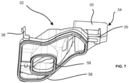
- a sectional view of the grip shell 70 with the shell component 32 inserted figure 4 shows figure 5 .
- a channel-shaped mouth area 37 formed in the handle shell 70 first extends behind the inlet opening 36 and forms part of the suction material guide 30 .
- the suction material guide 30 is composed of the mouth area 37 formed in one piece in the handle shell 70 and the multi-part area delimited by the handle shell 70 and the shell component 32 .
- the inlet opening 36 and the mouth area 37 form a kind of circular segment around the axis of the fan wheel.
- the inlet opening 36 and the mouth area 37 are arranged in the bulbous area of the suction device 2 accommodating the suction unit in the vicinity of the storage elements 74 .
- the one-piece opening area 37 of the suction material guide 30 gradually transitions into a lower area of the suction material guide 30 when the suction device 2 is switched off.
- the suction material guide 30 then extends on both sides around the wall surrounding the opening in the handle shell 70 into the outlet 34 of the shell component 32.
- the outlet 34 is arranged in the handle shell such that partial storage areas are formed peripherally to the outlet 34 in the suction material container 8, which receive the suction material when the device 2 is used as intended, in such a way that the suction material does not flow back through the outlet 34.
- the shell component 32 is placed with the seal on the one-piece mouth area 37 of the suction material guide 30 .
- the inlet opening 36 also has a sealing element 58 designed as a molded seal, which seals the separating area with the separating device against the escape of suction material.
- the construction arranged in this way has the advantage that only two components have to be sealed against each other.
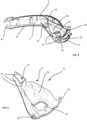
- FIG. 6 A perspective view of the shell component 32 from the previous figures show the figures 6 and 7 from diagonally above and diagonally below.
- the retaining lugs 38 already mentioned can be seen in the front area.
- the recess 82 in the shell component 32 and the positioning receptacle 80 can also be seen.
- the holding receptacle 39 arranged next to the outlet 39 of the suction material guide 30 is also shown.
- the outlet 34 of the suction material guide 30 is arranged on the side of the shell component 32 that faces the distal end of the suction device 2 when installed as intended and is formed solely by the shell component 32 .
- the outlet 34 is delimited on three sides by an outlet boundary wall 35, laterally to the interior of the device and to the exterior of the device (in the case of a device orientation according to figure 1 ) and in the direction of the suction nozzle 4.
- the outlet boundary wall 35 is partially adapted geometrically to the boundary of the suction material container 8, in particular to the shape of the cover element.
- the outlet 34 is thus directed towards the closure 42 and upwards towards the cover element. In this way, the suction material first reaches the part of the suction material container 8 that is located in the handle 48 and is then transferred to a lower-lying storage area of the suction material container 8 in the bulbous part of the suction device.
- the outlet 34 is also at a distance from the wall of the suction material container 8 .
- the suction material already present in the suction material container 8 can thus flow past the outlet 34 when the device 2 is pivoted, without getting into it.
Landscapes
- Hooks, Suction Cups, And Attachment By Adhesive Means (AREA)
- Closures For Containers (AREA)
Description
- Die Erfindung betrifft ein tragbares Sauggerät nach dem Oberbegriff des Anspruchs 1. Insbesondere betrifft die Erfindung ein tragbares Sauggerät mit einem in eine Saugdüse mündenden Saugkanal und mit einem Gehäuse, einem Sauggutbehälter und einem Saugaggregat zur Erzeugung einer Saugströmung, die einen an der Saugdüse anliegenden Saugunterdruck bereitstellt, und mit einer Abscheideeinrichtung, die die über die Saugdüse angesaugte Saugströmung in eine aus dem Sauggerät strömende Abluftströmung und in Sauggut in Form von Partikeln und/oder Fluidbestandteilen aufzuteilen vermag, wobei die abgeschiedenen Partikel oder Fluidbestandteile in dem Sauggutbehälter gesammelt sind. Insbesondere weisen diese Geräte auch eine Abziehlippe zum Abziehen von Flüssigkeiten auf, wobei die Abziehlippe an der Saugdüse angeordnet ist. Zudem sind diese Geräte üblicherweise batteriebetrieben und werden in der Hand eines Benutzers gehalten, während dieser die Abziehlippe entlang der abzusaugenden Fläche führt.
- Tragbare Geräte dieser Art sind unter anderem aus der
EP 2 845 530 B1 , derWO 2014/127656 A1 undUS 2018/070784 A1 bekannt. Die bekannten Sauggeräte werden verwendet, um ein Flüssigkeit-/Luftgemisch aufzusaugen. Dies kann, wie im Fall der genannten Vorrichtung, zum Aufsaugen von Flüssigkeit, zum Beispiel von einer ebenen Oberfläche wie einer Tischplatte, von Fensterscheiben oder Fliesen erfolgen. Zum rückständefreien Reinigen der Oberflächen ist bei den gattungsgemäßen Geräten eine an der Saugdüse angeordnete Abziehlippe vorgesehen. Bei solchen Geräten unterscheidet man zwei grundlegende Bauarten, Einkammer- und Zweikammersysteme. - Bei den Zweikammersystemen wird das Sauggut zunächst in einer ersten, häufig auch als Abscheidekammer bezeichneten Kammer abgeschieden. Das Sauggut wird anschließend über eine Sauggutführung in die zweite, häufig als Speicherkammer oder als Sauggutbehälter bezeichnete Kammer überführt. Um ein Rückströmen des Saugguts zurück in die erste Kammer zu verhindern, wird der Auslass des Sauggutführung regelmäßig mittig in dem Sauggutbehälter positioniert. Auf diese Weise wird um den Auslass der Sauggutführung ein Ausweichvolumen geschaffen, in das das bereits im Sauggutbehälter gespeicherte Sauggut beim Verschwenken des Geräts zwischengespeichert wird.
- In der Regel haben die Einkammersysteme eine solche Sauggutführung nicht.
- Bei den Sauggutführungen der gattungsgemäßen Saugeräte sind herstellungsbedingt nur einfache Geometrien möglich, die einen erhöhten Bauraumbedarf bedingen.
- Aufgabe der Erfindung ist es daher ein Sauggerät bereitzustellen, das bei niedrigen Herstellungskosten und guter Bauraumausnutzung ein einfaches Überführen des Saugguts von der Saugdüse in den Sauggutbehälter ermöglicht.
- Die Lösung der Aufgabe erfolgt erfindungsgemäß durch ein tragbares Sauggerät mit den Merkmalen des Anspruchs 1. Bevorzugte Ausgestaltungen der Erfindung sind in den Unteransprüchen und der nachfolgenden Beschreibung angegeben, die jeweils einzeln oder in Kombination einen Aspekt der Erfindung darstellen können.
- Erfindungsgemäß sieht das tragbare Sauggerät zwischen Saugkanal und Sauggutbehälter, insbesondere hinter der Abscheideeinrichtung, eine Sauggutführung vor, durch die das Sauggut bei bestimmungsgemäßer Verwendung des Sauggeräts in den Sauggutbehälter gelangt, wobei die geometrische Begrenzung der Sauggutführung mehrteilig ausgebildet ist und zumindest durch ein separates Schalenbauteil gebildet ist.
- Die erfindungsgemäße Lösung bietet einen Schutz gegen Sauggutrückströmung zurück in den Abscheidebereich bzw. in eine Abscheidekammer beim Verschwenken des Geräts. Zudem hat die erfindungsgemäße Ausgestaltung den Vorteil, dass durch das Verbinden von zwei Halbschalen eine komplizierte, gewundene und gewinkelte Konstruktion der Sauggutführung möglich ist, sodass ein gewünschtes Sauggerätedesign ausgebildet werden kann und insbesondere auch der zur Verfügung stehender Bauraum vollständig ausgenutzt werden kann.
- Außerdem bietet die Lösung eine einfache Herstellerbarkeit, da lediglich einfache Schalenbauteile hergestellt werden müssen.
- In einer bevorzugten Ausführungsform ist die geometrische Begrenzung der Sauggutführung zum Teil durch einen Wandbereich des Sauggutbehälters gebildet. Dabei kann der Wandbereich auch einen Teil des Gehäuses des Sauggeräts bilden.
- Die Form des Sauggeräts ist in einer besonders vorteilhaften Ausgestaltung der Erfindung so ausgebildet, dass sich das Sauggerät auf dem der Saugdüse gegenüberliegenden Endabschnitt in einen Griff des Sauggeräts erstreckt.Um eine besonders kompakte Bauform zu erreichen, ist bevorzugt vorgesehen, dass der Sauggutbehälter und die Sauggutführung zumindest teilweise im Griff angeordnet sind. Eine vorteilhafte Ausgestaltung des erfindungsgemäßen Sauggeräts sieht vor, dass die Sauggutführung zumindest teilweise, insbesondere vollständig im Sauggutbehälter angeordnet ist.
- Das Gehäuse des Griffs weist bevorzugt eine ein- oder mehrteilige Griffschale auf, wobei die geometrische Begrenzung der Sauggutführung zum Teil durch einen Bereich der Griffschale gebildet ist.
- Als besonders vorteilhaft für die Montage hat sich herausgestellt, dass das zumindest eine separate Schalenbauteil lösbar befestigt, insbesondere verklemmt und/oder verschraubt, innerhalb des Gehäuses angeordnet ist. Als lösbare Verbindung zum Halten des Schalenbauteils können beispielsweise Klemmnasen und oder Schnapphaken vorgesehen sein.
- Bei der bestimmungsgemäßen Verwendung des Geräts kann es vorkommen, insbesondere im Fall von tragbaren Sauggeräten, dass das Sauggerät um bis zu +/-180° geschwenkt wird. Um zu vermeiden, dass ein Rückströmen des Saugguts durch einen Auslass der Sauggutführung zurück in den Saugkanal und damit ein Austreten aus dem Gerät auftritt, ist der Auslass der Sauggutführung in dem Sauggutbehälter derart positioniert und ausgerichtet, dass jeweils peripher zum Auslass Teilspeicherbereiche im Sauggutbehälter gebildet sind, die bei bestimmungsgemäßer Verwendung des Geräts das Sauggut aufnehmen.
- So können, ausgehend vom Auslass, zwei gegenüberliegende Teilspeicherbereiche vorgesehen sein, wobei die Teilspeicherbereiche vorzugsweise ungefähr gleich groß sind, um ein Austreten von Sauggut bei Verschwenken des Geräts in unterschiedliche Richtungen zu vermeiden.
- Bei den beschriebenen Ausführungsformen ist es vorteilhaft, den Auslass beabstandet von der Wandung des Sauggutbehälters anzuordnen, insbesondere wenn der Sauggutbehälter im Griff angeordnet ist.
- Bevorzugt ist der in den Sauggutbehälter führende Auslass aus fertigungstechnischer Sicht und in Hinblick auf die Montage des Sauggeräts nur im separaten Schalenbauteil ausgebildet.
- Die einzelnen Bauteile, die die geometrische Begrenzung der Sauggutführung bilden, werden dichtend miteinander verbunden. Dies kann durch eine angespritzte Dichtung und/oder durch eine separate Dichtungseinlage erfolgen. Besonders vorteilhaft ist es das Schalenbauteil mit angespritzter Dichtung im Zweikomponentenspritzguss herzustellen.
- Alternativ oder ergänzend können ein oder mehrere Teile der die geometrische Begrenzung der Sauggutführung bildenden Bauteile miteinander stoffschlüssig verbunden sein.
- In einer vorteilhaften Ausgestaltung der Erfindung ist zumindest ein Verschlusselement vorgesehen, das eingerichtet ist, einen Einlass oder Auslass der Sauggutführung zu öffnen und/oder zu schließen. Bei dem Reinigungsvorgang wird das Sauggerät zunächst aufrecht von oben nach unten geführt und anschließend um 90° zu einer Seite geschwenkt oder es wird entsprechend andersherum verfahren. Das Verschlusselement öffnet bevorzugt in Abhängigkeit der Haltestellung den Einlass und/oder den Auslass der Sauggutführung.
- Bevorzugt können in dem Sauggerät ein oder mehrere Sensoren vorgesehen sein, wobei die Sensoren den Füllstand des Sauggut im Sauggutbehälter messen und/oder die Neigung bzw. Lage des Sauggutbehälters messen. Über eine Elektronik können die Signale der Sensoren verwendet werden, um beispielsweise ein Verschlusselement und/oder das Saugaggregat zu steuern.
- Für den Füllstand im Sauggutbehälter kann das Verschlusselement selbst auch die Funktion des Füllstandsensors übernehmen. Das Verschlusselement kann dann entsprechend durch den Auftrieb des das Verschlusselement umgebenden Saugguts den Einlass und/oder Auslass der Sauggutführung öffnen oder schließen. Auf diese Weise wird verhindert, dass durch einen zu vollen Sauggutbehälter das Sauggut durch den Auslass zurück in den Saugkanal und damit aus der Saugdüse tritt.
- Ferner kann vorgesehen sein, dass das Verschlusselement magnetisch den Einlass und/oder Auslass der Sauggutführung öffnet oder schließt. Als Eingangsgröße kann auch hier ein Sensorsignal von einem der zuvor erwähnten Sensoren, zum Beispiel von einem im Sauggutbehälter angeordneten Schwimmer oder einem Lagesensor dienen.
- Weitere Merkmale und Vorteile der Erfindung ergeben sich der nachfolgenden Beschreibung bevorzugter Ausführungsbeispiele anhand der Zeichnungen.
- In den Zeichnungen zeigt:
- Fig. 1
- eine Seitenansicht des erfindungsgemäßen Sauggeräts in einer ersten Ausführungsform,
- Fig. 2
- eine perspektivische Ansicht des erfindungsgemäßen Sauggeräts mit abgezogenem Verschluss,
- Fig. 3
- eine perspektivische Ansicht des erfindungsgemäßen Sauggeräts mit freigeschnittenem Abscheidebereich,
- Fig. 4
- eine perspektivische Ansicht einer Griffschale mit eingesetztem Schalenbauteil des Sauggeräts aus
Fig. 1 , - Fig. 5
- eine Schnittansicht der Griffschale mit eingesetztem Schalenbauteil aus
Fig. 4 , - Fig. 6
- eine perspektivische Ansicht eines Schalenbauteils der Sauggutführung aus
Fig. 4 von oben, und - Fig. 7
- eine perspektivische Ansicht eines Schalenbauteils der Sauggutführung aus
Fig. 3 von unten. - In
Figur 1 ist das Sauggerät 2 in einer Seitenansicht dargestellt. Das Sauggerät 2 ist als ein handbetätigter Fenstersauger ausgebildet. Das Sauggerät 2 umfasst im vorderen Bereich eine als Flachdüse ausgeführte Saugdüse 4 mit oberhalb und unterhalb der Flachdüsenöffnung angeordneten Abziehlippen 5, die an einer sich aus zwei parallelen Ebenen bildenden schnabelförmigen Aufnahme 62 über eine Klemmverbindung lösbar angeordnet ist. In Strömungsrichtung weisend weist das Sauggerät 2 einen sich an die Saugdüse 4 anschließenden Ansaug- und Abscheidebereich, ein Saugaggregat 10, einen Sauggutbehälter 8 und einen Verschluss 42 auf. Die zuvor genannten Komponenten sind von einem Gehäuse 6 des Sauggeräts 2 aufgenommen. - Hinter der schnabelförmigen Aufnahme 62 ist das Sauggeräts 2 zunächst im Bereich des Abscheidebereichs und des Saugaggregats 10 bauchig geformt und erstreckt sich anschließend in einen hinteren Bereich, der einen Handgriff 48 bildet. Der Handgriff 48 schließt am distalen Ende mit dem Verschluss 42 ab. Der Sauggutbehälter 8 befindet sich größtenteils in dem Handgriff 48 und erstreckt sich bis zum Ende des Handgriffs 48. Am distalen Ende des Handgriffs 48 ist eine Öffnung 40 im Sauggutbehälter 8 vorgesehen, die durch den Verschluss 42 gegen Austritt von Sauggut, insbesondere Wasser, dichtend verschlossen ist.
- Das Gehäuse 6 des Sauggeräts 2 ist mehrteilig ausgebildet. Es umfasst eine obere Schale 64, welche Lüftungsschlitze 66 für die Abluftströmung und eine Aussparung für einen Betätigungsknopf 68 zum An- und Ausschalten des Geräts 2 aufweist. Die obere Schale 64 des Gehäuses 6 ist auf einen unteren Teil des Gehäuses aufgesetzt. Der untere Teil des Gehäuses bildet als eine Griffschale 70 einen Teil des Handgriffs 48, wobei der Handgriff 48 mehrteilig ausgeführt ist. Die Griffschale 70 wiederum bildet gleichzeitig eine untere Begrenzung des Sauggutbehälters 8. Ansaug- und Abscheidebereich sind jeweils von einem vorderen Teil des Gehäuses 6, der zudem die Aufnahme für die Saugdüse 62 ausbildet, aufgenommen.
- Die Form des Sauggerätes 2 ist derart ausgebildet, dass sich das Gerät 2 bei dessen Abstellen auf eine ebene Abstellfläche 72 von zwei Abstellbereichen aufgenommen ist. Den ersten Abstellbereich bildet der untere Teil der Griffschale 70, an dem zwei Füße als Abstellelemente 74 vorgesehen sind. Die zwei Abstellelemente 74 sind beidseitig von einer Längsachse des Sauggeräts 2 beabstandet angeordnet. Den zweiten Abstellbereich bildet ein Teil des Verschlusses 42. Durch die beiden Abstellelemente 74 kann das Sauggerät 2 kippstabil auf die ebene Abstellfläche 72 hingestellt werden. Die Abstellbereiche sind so am Sauggerät 2 angeordnet, dass die Saugdüse 4 und insbesondere die Abziehlippe 5 von der ebenen Abstellfläche 72 beabstandet ist. Sowohl der Außenbereich des Verschlusses 42 als auch die als Füße ausgebildeten Abstellelemente 74 sind aus einem Weichmaterial, insbesondere aus einem gummiartigen Material gebildet. Hierdurch wird neben einem stabilen und oberflächenschonenden Stand des Geräts 2 beim Abstellen des Geräts 2 auch eine Beschädigung bei der Benutzung des Geräts 2, bei nicht bestimmungsgemäßer Berührung des Geräts 2 mit der zu reinigenden Oberfläche oder den darum liegenden Oberflächen vermieden.
-
Figur 2 zeigt eine perspektivische Ansicht des Sauggeräts 2 ausFigur 1 . Zu erkennen ist der obere Teil der Aufnahme der Saugdüse 62, in der die als Flachdüse ausgebildete Saugdüse 4 lösbar über die Klemmverbindung eingesetzt ist. Durch die lösbare Verbindung können, je nach Anwendungsbereich, auch andere Saugdüsen in die Aufnahme der Saugdüse eingesetzt werden. Der die Außenkontur des Geräts 2 fortführende Verschluss 42 ist im demontierten Zustand beabstandet vom Sauggerät 2 dargestellt. Der Verschluss 42 weist am Ende einen Greifbereich auf, der durch einen erhöhten Rand in Form eines Haltewulstes 76 im hinteren Bereich gebildet ist. -
Figur 3 zeigt eine weitere Ansicht des erfindungsgemäßen Saugeräts 2 aus den vorherigen Figuren. Das Sauggerät 2 ist mit freigeschnittenem Abscheidebereich und ohne obere Gehäuseschale 64 sowie ohne Verschluss 42 dargestellt. - Das durch die nicht dargestellte Saugdüse 4 angesaugte Sauggut wird über einen in der Aufnahme für die Saugdüse 62 angeordneten Saugkanal 3 in den Abscheidebereich überführt, und durch die Abscheideeinrichtung 12 von der Abluftströmung getrennt und in eine im unteren Teil des Sauggeräts 2 angeordnete Einlassöffnung 36 überführt. Die Einlassöffnung 36 führt in die Sauggutführung 30, über die das Sauggut wiederum in den Sauggutbehälter 8 geleitet ist.
- Im freigeschnittenen Bereich sind die einzelnen Komponenten der Abscheideeinrichtung 12 zu erkennen, welche ein rampenförmiges Sauggutleitelement 14 und einem Rotationsabscheider 16 umfasst. Der Rotationsabscheider 16 ist in der dargestellten Ausführungsform einstückig mit dem Lüfterrad 11 des Saugaggregats 10 verbunden.
- Der Abscheidebereich ist in der gezeigten Ausführungsform als Abscheidekammer 18 ausgebildet. Die die Abscheidekammer 18 bildende Begrenzung ist zweiteilig ausgeführt. Den ersten Teil bildet ein becherförmiges erstes Begrenzungselement 92, in dessen Bodenbereich auch die schnabelförmige Aufnahme für die Saugdüse 62 ausgebildet ist. Das becherförmige Begrenzungselement 92 ist gleichzeitig auch Teil des Sauggerätegehäuses 6. Den zweiten Teil der Abscheidekammerbegrenzung bildet ein als ein tellerförmiges Begrenzungselement gebildetes Abdeckelement 94, das mit dem becherförmigen Begrenzungselement 92 verbunden ist. Das Abdeckelement 94 weist zwei Öffnungen auf. In der ersten Öffnung, die mittig in dem Abdeckelement angeordnet ist und eine Abluftöffnung ist, ist der einstückig mit dem Lüfterrad 11 verbundene Rotationsabscheider 16 angeordnet. Im Betrieb wird die von Sauggut befreite Abluftströmung durch die Abluftöffnung aus der Abscheidekammer 18 über das Lüfterrad 11 durch die Lüftungsschlitze 66 im Sauggerätgehäuse 6 nach außen gefördert. Die zweite Öffnung ist eine Ablauföffnung der Abscheidekammer 18 und ist gleichzeitig die Einlassöffnung 36 in die Sauggutführung 30.
- Eine perspektivische Ansicht von Teilen des Sauggeräts 2 aus den vorherigen Figuren zeigt
Figur 4 . Bei der erfindungsgemäßen Konstruktion ist der Sauggutbehälter 8 zu großen Teilen in dem Handgriff 48 angeordnet. Eine Wandung des Sauggutbehälters 8 bildet die Griffschale 70, die den unteren Teil des Gehäuses 6 bildet, und nach oben hin das nicht dargestelltes Deckelelement, welches gegen Austritt von Sauggut dichtend mit der Griffschale 70 verbunden wird. Eine weitere Wandung des Sauggutbehälters 8 bildet ein in die Griffschale 70 eingesetztes Schalenbauteil 32. - Das Schalenbauteil 32 ist ein separates Bauteil und ist über eine Klemmverbindung mit der Griffschale 70 verbunden. Hierfür sind im Bereich einer Einlassöffnung 36 symmetrisch beabstandet von der Längsachse des Sauggeräts 2 am Schalenbauteil 32 Haltenasen 38 vorgesehen, welche mit korrespondierend ausgebildeten Haltevorsprüngen 39 an der Griffschale 70 klemmend zusammenwirken. Am anderen Ende des Schalenbauteils 32 ist ein Haltevorsprung 39 vorgesehen, der für die Klemmverbindung mit einer korrespondierenden Haltenase 38, welche einstückig mit der Griffschale 70 verbunden ist, zusammenwirkt.
- Im der Saugdüse zugewandten Teil der Griffschale 70 ist die Einlassöffnung 36 in die Sauggutführung 30 vorgesehen. Über die Einlassöffnung 36 wird das in der Abscheideeinrichtung abgeschiedene Sauggut in die Sauggutführung 30 geleitet und von dort aus in den Sauggutbehälter 8. Die Entleerung des Sauggutbehälters 8 kann dann durch Öffnen des Verschlusses 42 erfolgen.
- Die Sauggutführung 30 ist mehrteilig ausgebildet. Einerseits erfolgt die geometrische Begrenzung der Sauggutführung 30 durch das Schalenbauteil 32 und andererseits durch Bereiche der Griffschale 70. Wie beschrieben ist das Schalenbauteil 32 ein separates Bauteil welches mit der Griffschale 70 verbunden ist. Zwischen dem Bereich des Schalenbauteil 32 und dem Bereich der Griffschale 70, welche jeweils die geometrische Begrenzung der Sauggutführung 30 bilden, sind Dichtmittel bzw. Dichtelemente 58 vorgesehen, die einen Austritt von Sauggut aus der Sauggutführung außerhalb der Ein- und Auslässe 36, 34 vermeiden. Die Dichtelemente 58 sind als umlaufende Dichtung ausgebildet, die an das Schalenbauteil angespritzt ist. Entsprechend der angespritzten Dichtung am Schalenbauteil 32 ist in der Griffschale 70 eine korrespondierende Dichtnut vorgesehen. Alternativ kann auch ein zweites Schalenbauteil eingesetzt werden, um zusammen mit dem Schalenbauteil 32 die Sauggutführung zu bilden.
- Vorteilhaft an dieser Konstruktion ist, dass auch komplexe Geometrien abgebildet werden können, da insbesondere die Griffschale 70 und das Schalenbauteil 32 als Halbschale gefertigt werden können und insbesondere Hohlräume und Hinterschneidungen in der Sauggutführung 30 durch den mehrteiligen Aufbau der Sauggutführung 30 fertigungs- und montagetechnisch umsetzbar sind. Ferner ist es auch problemlos möglich, in dem Schalenbauteil 30 Aussparungen 82 vorzusehen.
- Bei der erfindungsgemäßen Konstruktion ist in der Griffschale 70 ein Durchbruch ausgebildet, durch den eine Verkabelung für einen Ladeanschluss eines das Saugaggregat umfassenden Akkumulators durchgeführt ist. Der Ladeanschluss kann durch diese Konstruktion nicht unmittelbar für den Benutzer sichtbar auf der Unterseite des Geräts 2 in der Griffschale 70 angeordnet sein. Das Schalenbauteil 32 kann durch eine Aussparung 82, den Durchbruch der Griffschale 70 umgebend, angeordnet werden.
- Ferner können auch weitere Elemente an dem Schalenbauteil 32 vorgesehen werden, wie beispielsweise eine Positionieraufnahme 80, in die ein Teil des oberen nicht dargestellten Deckelelements abstützend und/oder zentrierend anordbar ist.
- Eine Schnittansicht der Griffschale 70 mit eingesetztem Schalenbauteil 32 aus
Figur 4 zeigtFigur 5 . Hinter der Einlassöffnung 36 erstreckt sich zunächst ein in der Griffschale 70 ausgebildeter kanalförmiger Mündungsbereich 37, der einen Teil der Sauggutführung 30 bildet. Somit setzt sich die Sauggutführung 30 aus dem in der Griffschale 70 einstückig ausgebildeten Mündungsbereich 37 und den mehrteiligen, durch die Griffschale 70 und das Schalenbauteil 32 begrenzten Bereich zusammen. - Die Einlassöffnung 36 und der Mündungsbereich 37 bilden von der Formgebung eine Art Kreissegment um die Lüfterradachse. Die Einlassöffnung 36 und der Mündungsbereich 37 sind in dem das Saugaggregat aufnehmenden bauchigen Bereich des Sauggeräts 2 in der Nähe der Abstellelemente 74 angeordnet.
- Der einteilig ausgebildeten Mündungsbereich 37 der Sauggutführung 30 geht stufenförmig zunächst in einen - bei abgestelltem Sauggerät 2 - unteren Bereich der Sauggutführung 30 über. Die Sauggutführung 30 erstreckt sich anschließend beidseitig um die den Durchbruch in der Griffschale 70 umgebende Wandung herum bis in den Auslass 34 des Schalenbauteils 32.
- Der Auslass 34 ist so in der Griffschale angeordnet, dass jeweils peripher zum Auslass 34 Teilspeicherbereiche im Sauggutbehälter 8 gebildet sind, die bei bestimmungsgemäßer Verwendung des Geräts 2 das Sauggut aufnehmen, derart, dass ein Rückströmen des Saugguts durch den Auslass 34 vermieden ist.
- Das Schalenbauteil 32 ist mit der Dichtung auf dem einstückig ausgebildeten Mündungsbereich 37 der Sauggutführung 30 aufgesetzt. Die Einlassöffnung 36 weist ebenfalls ein als angespritzte Dichtung ausgebildetes Dichtelemente 58 auf, welches den Abscheidebereich mit der Abscheideeinrichtung gegen Austritt von Sauggut abgedichtet.
- Die so angeordnete Konstruktion hat den Vorteil, dass jeweils nur zwei Bauteile gegeneinander abgedichtet werden müssen.
- Eine perspektivische Ansicht des Schalenbauteils 32 aus den vorherigen Figuren zeigen die
Figuren 6 und7 von schräg oben und schräg unten. Im vorderen Bereich sind die bereits erwähnten Haltenasen 38 zu sehen. Ferner ist die Aussparung 82 in dem Schalenbauteil 32 und die Positionieraufnahme 80 zu erkennen. InFigur 7 ist ferner die neben dem Auslass 39 der Sauggutführung 30 angeordnete Halteaufnahme 39 gezeigt. - Auf der bei bestimmungsgemäßer Montage dem distalen Ende des Sauggeräts 2 zugewandten Seite des Schalenbauteils 32 ist der Auslass 34 der Sauggutführung 30 angeordnet und wird alleine durch das Schalenbauteil 32 ausgebildet. Der Auslass 34 ist dabei an drei Seiten durch eine Auslassbegrenzungswandung 35 begrenzt, seitlich zum Geräteinneren und zum Geräteäußeren (bei einer Geräteausrichtung gemäß
Figur 1 ) sowie in Richtung der Saugdüse 4. Die Auslassbegrenzungswandung 35 ist teilweise geometrisch an die Begrenzung des Sauggutbehälters 8 angepasst, insbesondere an die Formgebung des Deckelelements. Der Auslass 34 ist auf diese Weise in Richtung Verschluss 42 und nach oben in Richtung Deckelelement gerichtet. Auf diese Weise gelangt das Sauggut zunächst in den Teil des Sauggutbehälters 8, der sich im Handgriff 48 befindet, und wird anschließend in einen tieferliegenden Speicherbereich des Sauggutbehälters 8 im bauchigen Teil des Sauggeräts überführt. - Ferner ist der Auslass 34 auch von der Wandung des Sauggutbehälter 8 beabstandet. Das bereits im Sauggutbehälter 8 vorhandene Sauggut kann so beim Schwenken des Geräts 2 an dem Auslass 34 vorbeifließen, ohne in diesen zu gelangen.
- Die Gefahr eines Rückströmens des Saugguts aus dem Sauggutbehälter 8 bei einem Schwenken des Geräts 2 wird jeweils durch diese Maßnahmen bei bestimmungsgemäßer Betriebsweise verringert bzw. vermieden.
-
- 2
- Sauggerät
- 3
- Saugkanal
- 4
- Saugdüse
- 5
- Abziehlippen
- 6
- Gehäuse
- 8
- Sauggutbehälter
- 10
- Saugaggregat
- 11
- Lüfterrad
- 12
- Abscheideeinrichtung
- 14
- Sauggutleitelement
- 16
- Rotationsabscheider
- 18
- Abscheidekammer
- 19
- Abluftöffnung im Abdeckelement
- 20
- Einlaufstutzen
- 21
- Hineingreifschutz
- 22
- Aufnahmebereich
- 23
- Zwischenelement
- 27
- Deckelelement
- 30
- Sauggutführung
- 32
- Schalenbauteil
- 34
- Auslass der Sauggutführung
- 35
- Auslassbegrenzungswandung
- 36
- Einlass der Sauggutführung
- 37
- Einmündungsbereich
- 38
- Haltenasen
- 39
- Haltevorsprung
- 40
- Öffnung des Sauggutbehälters
- 41
- Wandung der Öffnung des Sauggutbehälters
- 42
- Verschluss
- 48
- Handgriff
- 58
- Dichtelemente
- 62
- Aufnahme für Saugdüse
- 64
- obere Gehäuseschale
- 66
- Lüftungsschlitze
- 68
- Betätigungsknopf
- 70
- Griffschale
- 72
- Abstellfläche
- 74
- Abstellelemente
- 76
- Haltewulst des Verschlusses
- 80
- Positionieraufnahme
- 82
- Aussparung in Schalenbauteil
- 92
- erstes Begrenzungselement des Abscheidebereichs
- 94
- zweites Begrenzungselement des Abscheidebereichs (Prallscheibe)
Claims (15)
- Tragbares Sauggerät (2) mit einem in eine Saugdüse (4) mündenden Saugkanal (3) und mit einem Gehäuse (6), einem Sauggutbehälter (8) und einem Saugaggregat (10) zur Erzeugung einer Saugströmung, die einen an der Saugdüse (4) anliegenden Saugunterdruck bereitstellt, mit einer Abscheideeinrichtung (12), die die über die Saugdüse (4) angesaugte Saugströmung in eine aus dem Sauggerät (2) strömende Abluftströmung und in Sauggut in Form von Partikeln und/oder Fluidbestandteilen aufzuteilen vermag, wobei die abgeschiedenen Partikel oder Fluidbestandteile in dem Sauggutbehälter (8) gesammelt sind, wobei zwischen Saugkanal (3) und Sauggutbehälter (8) eine Sauggutführung (30) vorgesehen ist, durch die das Sauggut bei bestimmungsgemäßer Verwendung des Sauggeräts (2) in den Sauggutbehälter (8) gelangt, dadurch gekennzeichnet, dass die geometrische Begrenzung der Sauggutführung (30) mehrteilig ausgebildet ist und zumindest durch ein separates Schalenbauteil (32) gebildet ist.
- Tragbares Sauggerät (2) nach Anspruch 1, dadurch gekennzeichnet, dass die geometrische Begrenzung der Sauggutführung (30) zum Teil durch einen Wandbereich des Sauggutbehälters (8) gebildet ist, wobei der Wandbereich insbesondere einen Teil des Gehäuses des Sauggeräts (6) bildet.
- Tragbares Sauggerät (2) nach einem der vorstehenden Ansprüche, dadurch gekennzeichnet, dass das Sauggerät (2) einen Griff (48) aufweist, wobei der Sauggutbehälter (8) und die Sauggutführung (30) zumindest teilweise im Griff (48) angeordnet sind.
- Tragbares Sauggerät (2) nach dem vorstehenden Anspruch, dadurch gekennzeichnet, dass der Griff (48) eine Griffschale (70) aufweist, und die geometrische Begrenzung der Sauggutführung (30) zum Teil durch einen Bereich der Griffschale (70) gebildet ist.
- Tragbares Sauggerät (2) nach einem der vorstehenden Ansprüche, dadurch gekennzeichnet, dass die Sauggutführung (30) innerhalb des Sauggutbehälters (8) angeordnet ist.
- Tragbares Sauggerät (2) nach einem der vorstehenden Ansprüche, dadurch gekennzeichnet, dass das zumindest eine separate Schalenbauteil (32) lösbar befestigt, insbesondere verklemmt und/oder verschraubt, innerhalb des Gehäuses (6) angeordnet ist.
- Tragbares Sauggerät (2) nach einem der vorstehenden Ansprüche, dadurch gekennzeichnet, dass ein Auslass (34) der Sauggutführung (30) in den Sauggutbehälter derart positioniert und ausgerichtet ist, dass jeweils peripher zum Auslass (34) Teilspeicherbereiche im Sauggutbehälter (8) gebildet sind, die bei bestimmungsgemäßer Verwendung des Geräts (2) das Sauggut aufnehmen, derart, dass ein Rückströmen des Saugguts durch den Auslass (34) vermieden wird.
- Tragbares Sauggerät (2) nach dem vorstehenden Anspruch, dadurch gekennzeichnet, dass ausgehend vom Auslass (34) der Sauggutführung (30) zwei gegenüberliegende Teilspeicherbereiche vorgesehen sind, wobei die Teilspeicherbereiche ungefähr gleich groß sind.
- Tragbares Sauggerät (2) nach einem der vorstehenden Ansprüche, dadurch gekennzeichnet, dass die Sauggutführung (30) zumindest einen in den Sauggutbehälter (8) führenden Auslass (34) aufweist und der Auslass (34) nur im separaten Schalenbauteil (32) ausgebildet ist.
- Tragbares Sauggerät (2) nach dem vorstehenden Anspruch, dadurch gekennzeichnet, dass der Auslass (32) von der Gehäusewandung des Sauggutbehälters (8) beabstandet ist.
- Tragbares Sauggerät (8) nach einem der vorstehenden Ansprüche, dadurch gekennzeichnet, dass die die geometrische Begrenzung der Sauggutführung (30) bildenden mehreren Bauteile der Sauggutführung (30) dichtend miteinander verbunden sind, insbesondere durch eine angespritzte Dichtung und/oder eine separate Dichtungseinlage.
- Tragbares Sauggerät (2) nach einem der vorstehenden Ansprüche 1 - 10, dadurch gekennzeichnet, dass die die geometrische Begrenzung der Sauggutführung (30) bildenden mehreren Bauteile der Sauggutführung (30) miteinander stoffschlüssig verbunden sind.
- Tragbares Sauggerät (2) nach einem der vorstehenden Ansprüche, dadurch gekennzeichnet, dass der Sauggutbehälter (8) zumindest abschnittsweise durch die Sauggutführung (30) begrenzt ist.
- Tragbares Sauggerät (2) nach einem der vorstehenden Ansprüche, dadurch gekennzeichnet, dass zumindest ein Verschlusselement vorgesehen ist, das eingerichtet ist, einen Einlass (36) oder Auslass (34) der Sauggutführung (30) zu öffnen und/oder zu schließen, wobei das Verschlusselement insbesondere in Abhängigkeit der Haltestellung des Sauggeräts (2) den Einlass (36) und/oder Auslass (34) der Sauggutführung (30) öffnet oder schließt.
- Tragbares Sauggerät (2) nach dem vorstehenden Anspruch, dadurch gekennzeichnet, dass das Verschlusselement durch Auftrieb des das Verschlusselement umgebenen Saugguts und/oder magnetisch den Einlass (36) und/oder Auslass (34) der Sauggutführung (30) öffnet oder schließt.
Priority Applications (2)
| Application Number | Priority Date | Filing Date | Title |
|---|---|---|---|
| PL19186087.3T PL3763264T3 (pl) | 2019-07-12 | 2019-07-12 | Przenośne urządzenie ssące |
| EP19186087.3A EP3763264B1 (de) | 2019-07-12 | 2019-07-12 | Tragbares sauggerät |
Applications Claiming Priority (1)
| Application Number | Priority Date | Filing Date | Title |
|---|---|---|---|
| EP19186087.3A EP3763264B1 (de) | 2019-07-12 | 2019-07-12 | Tragbares sauggerät |
Publications (3)
| Publication Number | Publication Date |
|---|---|
| EP3763264A1 EP3763264A1 (de) | 2021-01-13 |
| EP3763264B1 true EP3763264B1 (de) | 2023-06-07 |
| EP3763264C0 EP3763264C0 (de) | 2023-06-07 |
Family
ID=67262195
Family Applications (1)
| Application Number | Title | Priority Date | Filing Date |
|---|---|---|---|
| EP19186087.3A Active EP3763264B1 (de) | 2019-07-12 | 2019-07-12 | Tragbares sauggerät |
Country Status (2)
| Country | Link |
|---|---|
| EP (1) | EP3763264B1 (de) |
| PL (1) | PL3763264T3 (de) |
Families Citing this family (1)
| Publication number | Priority date | Publication date | Assignee | Title |
|---|---|---|---|---|
| USD1100392S1 (en) * | 2024-06-28 | 2025-10-28 | Hongliang Wu | Cordless vacuum cleaner |
Family Cites Families (3)
| Publication number | Priority date | Publication date | Assignee | Title |
|---|---|---|---|---|
| CN103099582B (zh) * | 2013-02-21 | 2015-09-16 | 中山市金舜家庭用品有限公司 | 一种玻璃表面清洁装置 |
| DE202013104011U1 (de) | 2013-09-05 | 2013-09-18 | Leifheit Ag | Tragbares Sauggerät für Flüssigkeiten oder Flüssigkeits-/Luftgemische |
| KR102476535B1 (ko) * | 2016-09-13 | 2022-12-09 | 엘지전자 주식회사 | 핸디형 잔수 흡입 장치 |
-
2019
- 2019-07-12 PL PL19186087.3T patent/PL3763264T3/pl unknown
- 2019-07-12 EP EP19186087.3A patent/EP3763264B1/de active Active
Also Published As
| Publication number | Publication date |
|---|---|
| EP3763264A1 (de) | 2021-01-13 |
| PL3763264T3 (pl) | 2023-08-14 |
| EP3763264C0 (de) | 2023-06-07 |
Similar Documents
| Publication | Publication Date | Title |
|---|---|---|
| EP3021727B1 (de) | Tragbares hartflächenreinigungsgerät | |
| DE68914431T2 (de) | Luftzufuhrabdichtung für Kesselstaubsauger. | |
| DE2545936A1 (de) | Geraet fuer die zahn- und mundpflege | |
| DE10200673A1 (de) | Kraftfahrzeug-Luftfilter | |
| WO2017108089A1 (de) | Saugdüse für ein hartflächenreinigungsgerät und hartflächenreinigungsgerät mit einer derartigen saugdüse | |
| EP1182958A1 (de) | Staubsauger | |
| EP3763264B1 (de) | Tragbares sauggerät | |
| EP3763265B1 (de) | Tragbares sauggerät | |
| EP3393320A1 (de) | Saugdüse für ein hartflächenreinigungsgerät und hartflächenreinigungsgerät mit einer derartigen saugdüse | |
| EP0655217B1 (de) | Elektro-Staubsauger mit einer Aufnahmekammer für einen Staubbeutel | |
| CH685327A5 (de) | Anschlussvorrichtung zum Anschliessen eines Gebläses an ein Schutzmaskenfilter. | |
| DE19915384A1 (de) | Spitzer für Weichstifte | |
| DE2535761A1 (de) | Absaugkanuele bzw. -roehre | |
| EP0176095B1 (de) | Gehäuse für einen Handstaubsauger | |
| EP4201282A2 (de) | Flächenreinigungsgerät | |
| EP3763267B1 (de) | Tragbares sauggerät | |
| DE102005041811A1 (de) | Staubsaugerbeutel mit Kunststoffflansch | |
| EP3763263B1 (de) | Tragbares sauggerät | |
| EP3393322A1 (de) | Tragbares hartflächenreinigungsgerät | |
| DE102009035652B4 (de) | Filterbeutel für einen Staubsauger | |
| EP3763266B1 (de) | Tragbares sauggerät | |
| EP2992799B1 (de) | Tragbares Sauggerät mit auswechselbarer Saugdüse | |
| EP0200084B1 (de) | Fahrzeugdach mit einer einen Deckel aufnehmenden Dachkassette | |
| DE19736596C2 (de) | Kleinstaubsauger mit Zusatzrohr | |
| DE202019103861U1 (de) | Tragbares Sauggerät |
Legal Events
| Date | Code | Title | Description |
|---|---|---|---|
| PUAI | Public reference made under article 153(3) epc to a published international application that has entered the european phase |
Free format text: ORIGINAL CODE: 0009012 |
|
| STAA | Information on the status of an ep patent application or granted ep patent |
Free format text: STATUS: REQUEST FOR EXAMINATION WAS MADE |
|
| 17P | Request for examination filed |
Effective date: 20200221 |
|
| AK | Designated contracting states |
Kind code of ref document: A1 Designated state(s): AL AT BE BG CH CY CZ DE DK EE ES FI FR GB GR HR HU IE IS IT LI LT LU LV MC MK MT NL NO PL PT RO RS SE SI SK SM TR |
|
| AX | Request for extension of the european patent |
Extension state: BA ME |
|
| GRAP | Despatch of communication of intention to grant a patent |
Free format text: ORIGINAL CODE: EPIDOSNIGR1 |
|
| STAA | Information on the status of an ep patent application or granted ep patent |
Free format text: STATUS: GRANT OF PATENT IS INTENDED |
|
| INTG | Intention to grant announced |
Effective date: 20221005 |
|
| GRAS | Grant fee paid |
Free format text: ORIGINAL CODE: EPIDOSNIGR3 |
|
| GRAA | (expected) grant |
Free format text: ORIGINAL CODE: 0009210 |
|
| STAA | Information on the status of an ep patent application or granted ep patent |
Free format text: STATUS: THE PATENT HAS BEEN GRANTED |
|
| AK | Designated contracting states |
Kind code of ref document: B1 Designated state(s): AL AT BE BG CH CY CZ DE DK EE ES FI FR GB GR HR HU IE IS IT LI LT LU LV MC MK MT NL NO PL PT RO RS SE SI SK SM TR |
|
| REG | Reference to a national code |
Ref country code: GB Ref legal event code: FG4D Free format text: NOT ENGLISH |
|
| REG | Reference to a national code |
Ref country code: CH Ref legal event code: EP Ref country code: AT Ref legal event code: REF Ref document number: 1572235 Country of ref document: AT Kind code of ref document: T Effective date: 20230615 |
|
| REG | Reference to a national code |
Ref country code: DE Ref legal event code: R096 Ref document number: 502019007889 Country of ref document: DE |
|
| U01 | Request for unitary effect filed |
Effective date: 20230615 |
|
| U07 | Unitary effect registered |
Designated state(s): AT BE BG DE DK EE FI FR IT LT LU LV MT NL PT SE SI Effective date: 20230621 |
|
| U20 | Renewal fee for the european patent with unitary effect paid |
Year of fee payment: 5 Effective date: 20230718 |
|
| REG | Reference to a national code |
Ref country code: LT Ref legal event code: MG9D |
|
| PG25 | Lapsed in a contracting state [announced via postgrant information from national office to epo] |
Ref country code: NO Free format text: LAPSE BECAUSE OF FAILURE TO SUBMIT A TRANSLATION OF THE DESCRIPTION OR TO PAY THE FEE WITHIN THE PRESCRIBED TIME-LIMIT Effective date: 20230907 Ref country code: ES Free format text: LAPSE BECAUSE OF FAILURE TO SUBMIT A TRANSLATION OF THE DESCRIPTION OR TO PAY THE FEE WITHIN THE PRESCRIBED TIME-LIMIT Effective date: 20230607 |
|
| PG25 | Lapsed in a contracting state [announced via postgrant information from national office to epo] |
Ref country code: RS Free format text: LAPSE BECAUSE OF FAILURE TO SUBMIT A TRANSLATION OF THE DESCRIPTION OR TO PAY THE FEE WITHIN THE PRESCRIBED TIME-LIMIT Effective date: 20230607 Ref country code: HR Free format text: LAPSE BECAUSE OF FAILURE TO SUBMIT A TRANSLATION OF THE DESCRIPTION OR TO PAY THE FEE WITHIN THE PRESCRIBED TIME-LIMIT Effective date: 20230607 Ref country code: GR Free format text: LAPSE BECAUSE OF FAILURE TO SUBMIT A TRANSLATION OF THE DESCRIPTION OR TO PAY THE FEE WITHIN THE PRESCRIBED TIME-LIMIT Effective date: 20230908 |
|
| PG25 | Lapsed in a contracting state [announced via postgrant information from national office to epo] |
Ref country code: SK Free format text: LAPSE BECAUSE OF FAILURE TO SUBMIT A TRANSLATION OF THE DESCRIPTION OR TO PAY THE FEE WITHIN THE PRESCRIBED TIME-LIMIT Effective date: 20230607 |
|
| PG25 | Lapsed in a contracting state [announced via postgrant information from national office to epo] |
Ref country code: IS Free format text: LAPSE BECAUSE OF FAILURE TO SUBMIT A TRANSLATION OF THE DESCRIPTION OR TO PAY THE FEE WITHIN THE PRESCRIBED TIME-LIMIT Effective date: 20231007 |
|
| PG25 | Lapsed in a contracting state [announced via postgrant information from national office to epo] |
Ref country code: SM Free format text: LAPSE BECAUSE OF FAILURE TO SUBMIT A TRANSLATION OF THE DESCRIPTION OR TO PAY THE FEE WITHIN THE PRESCRIBED TIME-LIMIT Effective date: 20230607 Ref country code: SK Free format text: LAPSE BECAUSE OF FAILURE TO SUBMIT A TRANSLATION OF THE DESCRIPTION OR TO PAY THE FEE WITHIN THE PRESCRIBED TIME-LIMIT Effective date: 20230607 Ref country code: RO Free format text: LAPSE BECAUSE OF FAILURE TO SUBMIT A TRANSLATION OF THE DESCRIPTION OR TO PAY THE FEE WITHIN THE PRESCRIBED TIME-LIMIT Effective date: 20230607 Ref country code: IS Free format text: LAPSE BECAUSE OF FAILURE TO SUBMIT A TRANSLATION OF THE DESCRIPTION OR TO PAY THE FEE WITHIN THE PRESCRIBED TIME-LIMIT Effective date: 20231007 |
|
| REG | Reference to a national code |
Ref country code: CH Ref legal event code: PL |
|
| REG | Reference to a national code |
Ref country code: DE Ref legal event code: R097 Ref document number: 502019007889 Country of ref document: DE |
|
| PG25 | Lapsed in a contracting state [announced via postgrant information from national office to epo] |
Ref country code: MC Free format text: LAPSE BECAUSE OF FAILURE TO SUBMIT A TRANSLATION OF THE DESCRIPTION OR TO PAY THE FEE WITHIN THE PRESCRIBED TIME-LIMIT Effective date: 20230607 |
|
| PG25 | Lapsed in a contracting state [announced via postgrant information from national office to epo] |
Ref country code: MC Free format text: LAPSE BECAUSE OF FAILURE TO SUBMIT A TRANSLATION OF THE DESCRIPTION OR TO PAY THE FEE WITHIN THE PRESCRIBED TIME-LIMIT Effective date: 20230607 |
|
| PLBE | No opposition filed within time limit |
Free format text: ORIGINAL CODE: 0009261 |
|
| STAA | Information on the status of an ep patent application or granted ep patent |
Free format text: STATUS: NO OPPOSITION FILED WITHIN TIME LIMIT |
|
| REG | Reference to a national code |
Ref country code: IE Ref legal event code: MM4A |
|
| PG25 | Lapsed in a contracting state [announced via postgrant information from national office to epo] |
Ref country code: CH Free format text: LAPSE BECAUSE OF NON-PAYMENT OF DUE FEES Effective date: 20230731 |
|
| 26N | No opposition filed |
Effective date: 20240308 |
|
| GBPC | Gb: european patent ceased through non-payment of renewal fee |
Effective date: 20230907 |
|
| PG25 | Lapsed in a contracting state [announced via postgrant information from national office to epo] |
Ref country code: IE Free format text: LAPSE BECAUSE OF NON-PAYMENT OF DUE FEES Effective date: 20230712 |
|
| PG25 | Lapsed in a contracting state [announced via postgrant information from national office to epo] |
Ref country code: GB Free format text: LAPSE BECAUSE OF NON-PAYMENT OF DUE FEES Effective date: 20230907 |
|
| PG25 | Lapsed in a contracting state [announced via postgrant information from national office to epo] |
Ref country code: IE Free format text: LAPSE BECAUSE OF NON-PAYMENT OF DUE FEES Effective date: 20230712 Ref country code: GB Free format text: LAPSE BECAUSE OF NON-PAYMENT OF DUE FEES Effective date: 20230907 |
|
| U20 | Renewal fee for the european patent with unitary effect paid |
Year of fee payment: 6 Effective date: 20240710 |
|
| U1N | Appointed representative for the unitary patent procedure changed after the registration of the unitary effect |
Representative=s name: KBN IP PATENTANWAELTE PARTNERSCHAFT MBB; DE |
|
| PGFP | Annual fee paid to national office [announced via postgrant information from national office to epo] |
Ref country code: PL Payment date: 20250616 Year of fee payment: 7 |
|
| PG25 | Lapsed in a contracting state [announced via postgrant information from national office to epo] |
Ref country code: CY Free format text: LAPSE BECAUSE OF FAILURE TO SUBMIT A TRANSLATION OF THE DESCRIPTION OR TO PAY THE FEE WITHIN THE PRESCRIBED TIME-LIMIT; INVALID AB INITIO Effective date: 20190712 |
|
| PGFP | Annual fee paid to national office [announced via postgrant information from national office to epo] |
Ref country code: CZ Payment date: 20250619 Year of fee payment: 7 |
|
| U20 | Renewal fee for the european patent with unitary effect paid |
Year of fee payment: 7 Effective date: 20250708 |
|
| PG25 | Lapsed in a contracting state [announced via postgrant information from national office to epo] |
Ref country code: HU Free format text: LAPSE BECAUSE OF FAILURE TO SUBMIT A TRANSLATION OF THE DESCRIPTION OR TO PAY THE FEE WITHIN THE PRESCRIBED TIME-LIMIT; INVALID AB INITIO Effective date: 20190712 |
|
| PG25 | Lapsed in a contracting state [announced via postgrant information from national office to epo] |
Ref country code: TR Free format text: LAPSE BECAUSE OF FAILURE TO SUBMIT A TRANSLATION OF THE DESCRIPTION OR TO PAY THE FEE WITHIN THE PRESCRIBED TIME-LIMIT Effective date: 20230607 |