EP3759397B1 - Hotte de table et procédé servant à nettoyer une hotte de table - Google Patents
Hotte de table et procédé servant à nettoyer une hotte de table Download PDFInfo
- Publication number
- EP3759397B1 EP3759397B1 EP19705522.1A EP19705522A EP3759397B1 EP 3759397 B1 EP3759397 B1 EP 3759397B1 EP 19705522 A EP19705522 A EP 19705522A EP 3759397 B1 EP3759397 B1 EP 3759397B1
- Authority
- EP
- European Patent Office
- Prior art keywords
- cleaning
- cleaning liquid
- filter element
- filter
- filter chamber
- Prior art date
- Legal status (The legal status is an assumption and is not a legal conclusion. Google has not performed a legal analysis and makes no representation as to the accuracy of the status listed.)
- Active
Links
Images


Classifications
-
- F—MECHANICAL ENGINEERING; LIGHTING; HEATING; WEAPONS; BLASTING
- F24—HEATING; RANGES; VENTILATING
- F24F—AIR-CONDITIONING; AIR-HUMIDIFICATION; VENTILATION; USE OF AIR CURRENTS FOR SCREENING
- F24F13/00—Details common to, or for air-conditioning, air-humidification, ventilation or use of air currents for screening
- F24F13/28—Arrangement or mounting of filters
-
- F—MECHANICAL ENGINEERING; LIGHTING; HEATING; WEAPONS; BLASTING
- F24—HEATING; RANGES; VENTILATING
- F24C—DOMESTIC STOVES OR RANGES ; DETAILS OF DOMESTIC STOVES OR RANGES, OF GENERAL APPLICATION
- F24C15/00—Details
- F24C15/20—Removing cooking fumes
- F24C15/2042—Devices for removing cooking fumes structurally associated with a cooking range e.g. downdraft
-
- B—PERFORMING OPERATIONS; TRANSPORTING
- B01—PHYSICAL OR CHEMICAL PROCESSES OR APPARATUS IN GENERAL
- B01D—SEPARATION
- B01D46/00—Filters or filtering processes specially modified for separating dispersed particles from gases or vapours
- B01D46/0002—Casings; Housings; Frame constructions
-
- F—MECHANICAL ENGINEERING; LIGHTING; HEATING; WEAPONS; BLASTING
- F24—HEATING; RANGES; VENTILATING
- F24C—DOMESTIC STOVES OR RANGES ; DETAILS OF DOMESTIC STOVES OR RANGES, OF GENERAL APPLICATION
- F24C15/00—Details
- F24C15/20—Removing cooking fumes
- F24C15/2035—Arrangement or mounting of filters
-
- F—MECHANICAL ENGINEERING; LIGHTING; HEATING; WEAPONS; BLASTING
- F24—HEATING; RANGES; VENTILATING
- F24C—DOMESTIC STOVES OR RANGES ; DETAILS OF DOMESTIC STOVES OR RANGES, OF GENERAL APPLICATION
- F24C15/00—Details
- F24C15/20—Removing cooking fumes
- F24C15/2057—Removing cooking fumes using a cleaning liquid
Definitions
- the present invention relates to a downdraft extractor and a method for cleaning a downdraft extractor.
- Vapors and vapors are produced when cooking on a hob.
- Vapor extraction devices are known by means of which vapors and vapors can be extracted and cleaned.
- extractor hoods are known that are mounted above the hob.
- table fans are known in which air is sucked downwards from the hob.
- the table fans can also be referred to as downdraft fans or table hoods and can be integrated into the hob or installed adjacent to the hob, for example in a worktop.
- a spray device for cleaning water in the extractor hood, through which part of the extractor hood is cleaned.
- a spray device is, for example, in DE 199 12 913 A1 described.
- the interior of the extractor hood is sprayed with cleaning water at intervals by means of a spray device and this is drawn off via a line from a sump at the bottom of the interior of the extractor hood.
- a disadvantage of this cleaning device is that the water requirement is large and cleaning can only take place in one mode, so that reliable cleaning is not ensured.
- a suction nozzle which has a suction inlet for sucking in cooking exhaust air, is mounted on the upper area of a cooker of a kitchen work station.
- a water spray nozzle is provided for cleaning the grease filter in the lower area of the kitchen work station.
- the water spray nozzle can be used to direct water onto the filter elements, which are arranged in a frame inside the extractor device. The filter elements can thus be cleaned.
- the cleaning fluid can be caught in a water pan on the floor of the kitchen work station and then returned to the nozzles by means of an electromagnetic pump.
- U.S. 2002 056 446 B2 describes a type of ventilation system with independent and modular components, including a chimney part, a connection component, a drying component and a water tank, which can be installed in a kitchen to form a chimney.
- the system can be flexibly installed depending on space requirements and the layout of the existing kitchen, so there is no need to dismantle the original equipment and buy a whole range of flues.
- sprinkler heads eject water in the form of a water curtain, thus cleaning the air that is drawn in.
- the recess can be closed by a closing element.
- the closing element is movable and, in the embodiment according to FIG. 6, can engage with the fixed filter insert.
- the closing element can be moved via a spindle.
- the filter insert is not movably arranged.
- the Post-Released EP 3 473 937 A1 discloses a vapor filter device for hobs, in particular for extracting and filtering cooking vapors below the hob level of a piece of kitchen furniture. Efficient removal of cooking vapors and easy cleaning of grease filters should be made possible.
- the vapor filter device comprises at least one closable inlet opening for cooking vapors in the hob level, which is assigned spatially close to a hob and which communicates with an air conveying unit.
- the inlet opening opens into a cleaning container, in which a grease separator unit through which the cooking vapors can flow is arranged.
- the cleaning container has an outlet for degreased air and in a bottom area an outlet for separated grease and a cleaning liquid.
- the invention is therefore based on the object of creating a solution by means of which a downdraft extractor can be reliably cleaned in a simple manner.
- the object is achieved by a table fan with a fan and an intake opening through which air is sucked in downwards, and a filter chamber with at least one filter element.
- the downdraft extractor is characterized in that the downdraft extractor comprises a cleaning device which has a circulation system for conducting cleaning liquid in a cleaning circuit and at least part of the filter element is in the cleaning circuit and the filter chamber consists of two housing parts and the suction opening in which the filter element is arranged is formed in a housing part which is at least partially extendable upwards.
- the downdraft extractor has a blower and a suction opening through which air is sucked in downwards.
- the suction opening can be in the horizontal or inclined to this, for example in the vertical.
- the downdraft extractor has a filter chamber with at least one filter element.
- a housing on which the suction opening is provided is referred to as a filter chamber.
- the filter element can be located in the suction opening or can be arranged in the flow direction after the suction opening in the filter chamber.
- the downdraft extractor includes a cleaning device which has a circulation system for conducting cleaning liquid in a cleaning circuit and at least part of the at least one filter element is located in the cleaning circuit.
- the circulation system can consist of different components.
- the circulation system can have lines, hoses and/or containers as components.
- pumps and valves can be provided in the circulation system.
- the cleaning device can have covers or flaps, through which the circulation system is closed during cleaning.
- the cleaning liquid can be water, for example.
- the circulation system serves to guide the cleaning agent in a cleaning circuit. The course of the cleaning liquid, in which it runs through the components of the circulation system at least once, is referred to as the cleaning cycle.
- the cleaning liquid is returned to a component of the circulation system from which the cleaning liquid was originally introduced into the cleaning cycle.
- at least part of the at least one filter element is in the cleaning circuit. This means that the cleaning liquid passes through at least part of the filter element during each cycle.
- the cleaning liquid preferably passes through at least part of the walls of the filter space.
- a number of advantages can be achieved by providing a circulation system according to the invention, via which a cleaning liquid can be guided in a cleaning circuit and at least part of the at least one filter element is located in the cleaning circuit.
- different cleaning cycles can be run.
- the cleaning liquid can have a different temperature or different composition in a first cleaning cycle than in a further cleaning cycle.
- the composition of the cleaning liquid in one cleaning cycle can consist exclusively of water, for example, and consist of water with a cleaning agent in another cleaning cycle.
- conducting the cleaning liquid in a cleaning cycle limits the amount of cleaning liquid, since it can be used several times to clean at least part of the filter element.
- the cleaning liquid can also be evaporated in a cleaning cycle, for example, and at least in that part of the cleaning cycle in which the Filter element is present as a vapor.
- a circulation system By providing a circulation system, at least part of the filter element can be cleaned as in a dishwasher and can be subjected to different cleaning cycles.
- the cleaning circuit is preferably a closed circuit.
- the circulation system of the cleaning device has a reservoir for the cleaning liquid, at least one nozzle directed at least temporarily towards the at least one filter element, at least one pump for pumping the cleaning liquid to the at least one nozzle, and at least one connecting line between the reservoir and the at least one nozzle for supplying cleaning liquid to the nozzle.
- the circulation system is thus essentially formed by the reservoir, the connecting line to the nozzles and the filter chamber, in or on which the filter element or elements are provided.
- the reservoir is preferably connected to the at least one nozzle for supplying cleaning liquid via the at least one connecting line.
- the connecting line can consist of one or more pipes and/or hoses.
- One or more nozzles can be provided in the cleaning device. If several nozzles are provided, they can be provided on a common pipe, for example. However, it is also within the scope of the invention to provide each nozzle with its own pipe through which the cleaning liquid is fed to the nozzle.
- the nozzle or nozzles are at least temporarily directed towards the filter element or filter elements. This means that the cleaning liquid is discharged at least in the direction of the filter element.
- the cleaning liquid emitted by the nozzle or nozzles can also be directed at at least part of the walls of the filter chamber.
- the nozzles can be permanently installed in the downdraft extractor or movably, in particular traversably or rotatably, supported in it.
- the cleaning device comprises at least one pump, through which the cleaning liquid is pumped to the at least one nozzle.
- the pump can be arranged in the reservoir or in the connecting line.
- the cleaning liquid is moved in the cleaning cycle by the pump.
- This embodiment of the cleaning device in which the circulation system has a reservoir, at least one nozzle, at least one pump and at least one connecting line between the reservoir and the at least one nozzle, has the advantage that the at least one filter element can be cleaned by the nozzles and the cleaning liquid used for this purpose can easily be fed back into the cleaning cycle.
- the position of the filter element does not have to be moved from the position in which it is in an operating state of the downdraft extractor or a resting state of the downdraft extractor for cleaning.
- the user does not have to remove the filter element from the downdraft extractor in order to clean it. Rather, the filter element can be cleaned automatically.
- the reservoir for the cleaning liquid can represent part of the filter space or be a separate container from the filter space.
- the reservoir is preferably positioned in such a way that it is located at least in regions below the filter element for collecting cleaning liquid from the filter element.
- the cleaning liquid can reach the reservoir from the filter element by gravity.
- the cleaning liquid can drip from the filter element into the reservoir.
- the liquid is conducted from the filter element via a line between the filter space and the reservoir. In this case, too, gravity can be used in a reservoir that is below the filter element, that is to say that is lower than the filter element, in order to direct the cleaning liquid to the reservoir.
- the filter chamber particularly preferably has a shape in the lower area that allows cleaning liquid to drain completely from the reservoir. In particular, this should make it easier to empty the reservoir at the end of the Cleaning process but also the complete return of the cleaning liquid from the reservoir to the one or more nozzles are made possible.
- the bottom of the filter chamber can be inclined at least in certain areas.
- the connecting line is preferably arranged in the lower area of the reservoir and in particular on the bottom of the reservoir.
- the cleaning liquid can be used in the cleaning circuit at room temperature or at the temperature it has in a supply line. However, according to the invention it is also possible to heat the cleaning liquid in the cleaning circuit at least temporarily.
- At least one heating element is preferably provided in the cleaning device for this purpose.
- the heating element is particularly preferably provided in the circulation system.
- the heating element or elements can be provided in the reservoir or in the connecting line. This makes it possible to heat the cleaning liquid, for example during one or more cleaning cycles, and thereby increase its cleaning effect.
- the provision of at least one heating element is particularly advantageous in the case of the inventive downdraft extractor, since the required heat output is minimized due to the cleaning liquid being guided in a cleaning circuit.
- the heating element is arranged in the reservoir, it can be provided, for example, at the bottom of the reservoir.
- an evaporator can be provided in the circulation system, in which the cleaning liquid is evaporated.
- the vaporizer is arranged in such a way that the vaporized cleaning liquid is discharged through the nozzles as vapor at least onto the filter element.
- the vapor condenses on the filter element and thus returns to the reservoir in the liquid state as cleaning liquid.
- the cleaning device has at least one supply connection for supplying cleaning liquid into the cleaning circuit and at least one discharge connection for draining cleaning liquid from the cleaning circuit.
- the supply connection can represent an opening in the filter chamber to which a supply line can be connected.
- the supply connection can be provided on the connection line of the circulation system and can represent a branch, for example, to which a supply line can be connected.
- the supply line can be, for example, a water line in a house, which is usually laid in kitchens. This makes it possible to add cleaning liquid, for example fresh water, to the cleaning circuit during the cleaning process, for example between cleaning cycles or during a cleaning cycle.
- the supply connection is arranged on the filter chamber and is positioned such that it is at a distance from the reservoir. If the reservoir is formed by the lower area of the filter chamber, the supply connection is at a distance from the maximum filling level of cleaning liquid in the reservoir. This can prevent cleaning liquid from entering the supply line unintentionally.
- the cleaning device preferably has at least one drainage connection for draining cleaning liquid from the cleaning circuit.
- the drain port can be provided on the reservoir or in the connecting line.
- a derivation which for example leads to a sewage line of the house, which is usually installed in kitchens, can be connected to the derivation connection.
- the cleaning liquid can be partially or completely removed from the cleaning cycle via the waste water line. In particular, the cleaning liquid can be let out via the waste water line between cleaning cycles or after the entire cleaning process.
- the supply connection and the discharge connection allow the cleaning device and in particular the circulation system to be connected to the water system of a kitchen in a simple manner.
- the intake opening of the downdraft extractor can represent the upper edge of a box-shaped filter chamber.
- the suction opening can also be on one side of a part of the filter chamber.
- the filter chamber consists of two housing parts and the suction opening is formed in a housing part which can be extended upwards at least in certain areas. It is therefore an extendable table fan.
- the intake opening can be provided, for example, in a side wall of the housing part, which can be extended.
- the other housing part is preferably held firmly in the downdraft extractor.
- the housing part on which the suction opening is provided can be extended via an extension device which can be mounted, for example, on or in the fixed housing part.
- the extension device can be a spindle, for example.
- the suction opening is preferably provided on the filter chamber and in particular on the movable housing part in such a way that flow can only take place through it when the housing part is in the extended or partially extended state.
- the intake opening is above the fixed housing part.
- the filter element is arranged in the suction opening.
- the retracted position of the movable housing part it is preferably accommodated in the fixed housing part.
- the suction opening and the filter element, which is preferably arranged at the suction opening, are therefore also located in the retracted state in the interior of the fixed housing part. The filter element can thus be cleaned there.
- the invention in which the housing part on which the suction opening is provided can be extended, has a number of advantages.
- the nozzle or nozzles can be arranged in the fixed housing part and only lie in front of the filter element in the direction of flow when the movable housing part is in the retracted state.
- the nozzles In the extended state, ie in the operating state, on the other hand the nozzles can thus be located behind the filter element in the direction of flow and are thus protected from contamination.
- the movable housing part can automatically close the filter chamber in the retracted position.
- a wall of the movable housing part which is open at the bottom, can cover the inlet of a suction pipe that leads from the filter chamber.
- the lower housing part of the filter chamber and thus the entire filter chamber can be closed at the top through the upper side of the movable housing part in the retracted state.
- an intermediate position of the movable housing part can also be set by only partially extending it upwards.
- the extendable table extractor can be used to extract air from a greater height above the hob, for example from pots.
- the downdraft extractor has a cover that at least temporarily closes off the filter chamber at the top.
- the cover can be provided on the upper side of the extendable housing part.
- the cover can be provided as a pivotable flap on the upper side of the filter chamber or can be designed to be removable from the filter chamber.
- the cleaning cycle can be completed by temporarily closing the filter chamber at the top. This prevents cleaning fluid from escaping during the cleaning process.
- a cover that seals the filter chamber for example by means of a sealing lip, it is possible to evaporate the cleaning liquid in part of the cleaning circuit.
- the cleaning liquid can be evaporated in front of the nozzle or nozzles and the filter chamber and in particular the filter element or elements can be cleaned with steam.
- the downdraft extractor preferably has a flap that closes off the filter space from a suction pipe.
- a suction pipe is provided on the filter room, which is connected to the blower of the downdraft extractor.
- this suction tube must be closed to prevent cleaning liquid from entering the suction tube and thus the blower.
- the suction tube can be closed by a flap that is pivotably or displaceably mounted on the inlet of the suction tube. In the embodiment in which the filter chamber consists of two housing parts, this flap can be replaced by a wall of the movable housing part.
- the downdraft extractor has at least one control unit for the automatic cleaning of the at least one filter element by the cleaning device.
- the control device serves in particular to add a cleaning liquid to the cleaning circuit and to move the cleaning liquid in the cleaning circuit.
- the control unit can in particular control the pump and any valves provided for supplying and discharging the cleaning liquid and—if provided—a heating element and/or evaporator.
- the control unit can automatically close the filter chamber before cleaning begins.
- the movable housing part can be retracted here, or a cover on the top and a flap on the suction pipe can be moved in order to close the filter chamber.
- cleaning liquid is preferably fed into the cleaning circuit. This can be done, for example, via a supply line that is connected to the water line in the kitchen. Water is preferably supplied until the reservoir is completely filled or filled to a desired level.
- the cleaning liquid is pumped from the reservoir to the nozzles that are provided in or on the filter chamber. This is preferably done via the connecting line so that the cleaning liquid is pumped to the nozzles.
- the cleaning liquid is sprayed into the filter chamber and preferably onto the filter element or elements via the nozzles.
- the cleaning liquid is collected again in the reservoir by the walls of the filter chamber or by the filter element or elements. The pumping and collecting steps are then repeated.
- the cleaning liquid passes through the filter chamber several times and the filter chamber and in particular the filter elements provided therein or on it can be reliably cleaned.
- the method comprises the step of discharging the cleaning liquid from the cleaning circuit after at least one pass of the pumping and collecting steps, followed by a step of supplying further cleaning liquid into the cleaning circuit and at least one further pass of pumping and collecting.
- the cleaning liquid can be removed between cleaning cycles and replaced with fresh cleaning liquid, thus ensuring reliable cleaning of the downdraft extractor.
- the circulation system is preferably emptied.
- the method includes the step of adding a cleaning agent to the cleaning cycle.
- the cleaning agent is preferably added to the cleaning liquid in the reservoir.
- the cleaning agent can be a liquid or solid cleaning agent.
- the cleaning agent can preferably consist of several components which differ in their properties. This cleaning agent is called a multi-component cleaning agent.
- one component can dissolve faster in the cleaning liquid than another component.
- one component can, for example, only dissolve or become active at elevated temperatures, while another component already dissolves or becomes active at lower temperatures.
- the cleaning effect is further improved. Since the cleaning liquid is guided in a cleaning circuit in the method according to the invention, the need for cleaning agents is minimized. In addition, a multi-component cleaning agent can be used, since different conditions can be set in the cleaning cycle.
- the method includes the step of heating the cleaning liquid.
- improved cleaning can be ensured.
- a cleaning agent with different components that dissolve at different temperatures or become active at different temperatures can be used.
- the method includes the step of drying the circulation system, in which at least the filter chamber and in particular at least the filter element are dried.
- the step of drying can initially drain or derive the cleaning liquid from the include cleaning cycle.
- the ventilation device of the downdraft extractor can be operated, as a result of which air is passed through the at least one filter element and this is dried.
- the method is carried out automatically according to a program stored in a control unit.
- Different programs can be stored here, which can be selected individually or jointly by the user of the downdraft extractor.
- a quick cleaning program can be stored.
- the cleaning device can be operated, for example, with water as the cleaning liquid and the water can be heated in the cleaning device or hot water can be entered into the cleaning circuit.
- Another program is a steam treatment. This can be selected, for example, to facilitate subsequent manual cleaning.
- cleaning liquid is fed into the cleaning circuit and evaporated there.
- a program can be programmed for normal or intensive cleaning.
- water can be used as the cleaning liquid, which is heated in the cleaning circuit in at least one cleaning cycle.
- Detergent can also be added to this program. The addition can be done manually.
- Another program can be drying.
- the cleaning liquid can first be removed from the cleaning circuit and then the ventilation device can be operated in order to dry the filter element with the air flow.
- a descaling program can also be provided.
- a special detergent can be added to this program.
- FIG 1 a schematic basic representation of an embodiment of a downdraft extractor 10 is shown.
- the downdraft extractor 10 is part of a combination appliance 1, which also includes a hob 11, of which figure 1 only two cooking zones 110 are shown.
- the table fan 10 is integrated into the hob 11.
- the table fan 10 comprises a ventilation device 3 and a cleaning device 2.
- the ventilation device 3 and its function are described with reference to FIG figure 2 described in more detail, in which the downdraft extractor 10 is shown for better visibility without a cleaning device.
- the ventilation device 3 has a filter chamber 30, which can also be referred to as a housing.
- the filter space 30 is arranged between the cooking zones 110 of the hob 11 .
- the filter chamber 30 is a box-shaped housing which is open towards it.
- the opening of The suction opening 33 of the ventilation device 3 is at the top of the filter chamber 30 .
- At least one filter element 32 is arranged in the filter chamber 30 . In the embodiment after figure 2 only one filter element 32 is shown.
- the filter element 32 lies obliquely in the filter chamber 30.
- a suction pipe 31, which is connected to a blower (not shown), is connected to the filter chamber 30 on a side wall.
- the filter element 32 is arranged in such a way that it completely covers the inlet of the suction pipe 31 in a perpendicular projection onto the inlet.
- the blower (not shown) When the ventilation device 3 is in operation, the blower (not shown) generates a negative pressure. Due to this negative pressure, air is sucked in through the suction pipe 31 . Since the suction pipe 31 is connected to the filter room 30 , air is sucked into the filter room 30 via the suction opening 33 .
- the downdraft extractor 2 has, in addition to the ones described and in figure 2 Ventilation device 3 shown also has a cleaning device 2 .
- a cover 34 is additionally provided on the ventilation device 3 .
- the cover 34 temporarily covers the suction opening 34, that is to say it closes the filter chamber 30 at the top.
- a flap 35 is arranged at the inlet of the suction pipe 31 and temporarily closes it.
- the cleaning device 2 includes a circulation system 20.
- the circulation system 20 includes the filter chamber 30, a reservoir 22, a connecting line 23 and a nozzle 24 as components in which a cleaning liquid is guided in a cleaning circuit 21.
- the circulation system also includes 20 a pump 27 and a heating element 26.
- the pump 27 and the heating element 26 are in the connecting line 23.
- the cleaning device 2 comprises a Supply line 250 and a discharge line 290. In the supply line 250 and the discharge line 290, a valve 28, 280 is provided in each case.
- valves 28, 280 are not arranged in the supply line 250 and the discharge line 290 but, for example, at the end of the supply line 250 or a branch in the discharge line 290.
- a branch is provided in the connection line 23, which branch serves as a discharge connection 29 to which the discharge line 290 is connected.
- the filter chamber 30 has a shape in which the bottom of the filter chamber 30 is inclined to one side.
- the connecting line 23 is connected to the filter chamber 30 in such a way that it is located in the area of the filter chamber 30 where it has a greater height, ie in the lower area of the sloping floor.
- the lower area of the filter chamber 30 forms the reservoir 22 of the circulation system 20.
- the reservoir it is also within the scope of the invention for the reservoir to be a component separate from the filter chamber 30, which is below the filter chamber 30 and connected to the filter chamber 30 for conducting cleaning liquid is connected to the reservoir, for example via a further line (not shown).
- the connecting line 23 is arranged in the lower end of the side wall of the filter chamber 30 .
- the connecting line can also be provided at a different point, for example in the bottom of the filter chamber 30 .
- the feed line 250 is arranged in the upper area of the side wall of the filter chamber 30, that is to say it opens into this filter chamber 30 in the upper area.
- the feed line 250 can also open out into the filter chamber 30 at a different point.
- the supply line 250 is arranged in such a way that it does not come into contact with the cleaning liquid R that collects in the reservoir 22 . This prevents cleaning liquid R from getting into the household water cycle.
- the ventilation device 3 of the downdraft extractor 10 After the ventilation device 3 of the downdraft extractor 10 has been used, it can be cleaned automatically with the cleaning device 2 according to the invention.
- valve 28 in the supply line 250 can be opened, as a result of which cleaning liquid R, in particular water, is fed into the filter chamber 30 .
- the amount of cleaning liquid R is preferably adjusted via a controller (not shown). The quantity is measured in such a way that there is sufficient cleaning liquid R in the cleaning circuit 21 to fill the reservoir 22 and the connecting line 23 .
- Cleaning liquid R is pumped from the reservoir 22 into the connecting line 23 via the pump 27 .
- the cleaning liquid R can be heated via the heating element 26 and optionally also evaporated.
- the cleaning liquid R is then discharged through the nozzle 24 .
- the nozzle 24 is directed at least onto the filter element 32 .
- the cleaning liquid R which runs down in or on the filter element 32 or drips from it, returns to the reservoir 22.
- both the cover 34 and the flap 35 are positioned in such a way that they cover the suction opening 33 or the inlet of the suction pipe 31 close. This cleaning process can be carried out until the filter element 32 has been freed from contamination.
- a cleaning agent RM in the form of a tab is shown schematically in the cleaning liquid R. This can be added to the cleaning liquid R before or during the cleaning process.
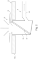
- FIG 3 an embodiment of a downdraft extractor 10 according to the invention is shown.
- This embodiment is a so-called down-draft table fan.
- the embodiment according to figure 3 differs from the table fan of figure 1 on the one hand by the arrangement of the table fan 10 with respect to the hob 11.
- the table extractor 10 is behind or next to the hob 11, from which in figure 3 only one cooking zone 110 is shown.
- the ventilation device 3 of the second embodiment comprises a multi-part filter chamber 30.
- the filter chamber 30, which can also be referred to as a housing, consists of a fixed lower housing part 300 and a movable upper housing part 301.
- the upper housing part 301 is shown in the extended position in relation to the lower housing part 30, which can also be referred to as the operating position of the downdraft extractor 10.
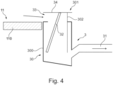
- the lower case 300 corresponds to the filter room 30 of the first embodiment.
- the upper case 301 includes the cover 34 forming the top of the upper case 34 .
- the upper housing part 301 has a rear wall 302 which extends downward from the cover 34 .
- the filter element 32 is attached to the upper housing part 301 .
- the filter element 32 is aligned in such a way that it is accommodated in the upper housing part 301 at an angle from the vertical.
- the filter element 32 it is also within the scope of the invention for the filter element 32 to be held vertically in the upper housing part 301 .
- the upper housing part 301 is open at the bottom.
- the suction opening 33 of the ventilation device 3 is located on the side of the housing part 301 which is opposite the rear wall 302 and on which the filter element 32 is arranged figure 5 indicated schematically by arrows.
- the lower housing part 300 of the filter chamber 30 is open at the top.
- the upper housing part 301 is inserted into the lower housing part 300 through the opening of the lower housing part 300 .
- the suction pipe 31 is connected in a wall, this is in contrast to the ventilation device figure 1 , formed from the filter chamber 30 rising upwards. But it is also within the limits of the invention that the suction pipe 31 runs horizontally.
- the bottom of the lower case 300 is inclined according to the first embodiment.
- the lower region of the filter chamber 30 and in particular of the lower housing part 300 also forms the reservoir 22 of the cleaning device 2 in this embodiment.
- the structure of the cleaning device 2 corresponds to the first embodiment, which is shown in figure 1 is shown and will therefore not be described again.
- the upper housing part 301 After the ventilation device 3 of the downdraft extractor 10 has been used, the upper housing part 301, as in figure 3 shown to be retracted into the lower housing part 300.
- the cover 34 closes the opening of the lower housing part 301 at the top.
- the rear wall 302 of the upper housing part 301 protrudes so far into the lower housing part 301 that this covers the suction pipe 31 at the front.
- the rear wall 302 is at a distance from the wall of the lower housing part 300 in which the supply connection and the inlet of the suction tube 31 lie.
- cleaning liquid R for example water, can be introduced into the lower housing part 300 of the filter chamber 30 via the supply line 250 .
- cleaning liquid can reach the bottom of the filter chamber 30, which serves as a reservoir 22. How out figure 3 As a result, cleaning agent R is preferably added to the reservoir 22 until the lower edge of the upper housing part 301, in particular the lower edge of the rear wall 302, projects into the cleaning agent.
- the cleaning of the downdraft extractor 10 can then be carried out as described above.
- the different cleaning programs described above can also be executed with the embodiment of the downdraft extractor 10 .
- the upper housing part 301 can be extended upwards far enough that the inlet of the exhaust pipe 31 is no longer blocked by the rear wall 302 .
- the fan (not shown) can be operated and the filter element 32 can be dried by the air flow.
- the supply line can be located at a point in the filter chamber that is below the exhaust air pipe.
- the supply line can also be on a different wall of the filter room than the exhaust air pipe.
- the connecting line can also be connected to another wall of the filter room, for example to the bottom of the filter room.
- the suction area and/or the suction pipe are preferably constructed in such a way that they can be closed or placed in such a way that the cleaning liquid cannot reach them.
- the table extractor which can also be referred to as a device, is connected to a water pipe, for example, in particular a fresh water pipe. Water pipes are usually located below the countertop in kitchens.
- the device is preferably connected to a drain, in particular to a sewage pipe.
- the device is built in such a way that no water remains in it.
- a tank can also be used in which the cleaning liquid used is collected after it has been drained from the cleaning circuit and disposed of at intervals.
Landscapes
- Engineering & Computer Science (AREA)
- Chemical & Material Sciences (AREA)
- Combustion & Propulsion (AREA)
- Mechanical Engineering (AREA)
- General Engineering & Computer Science (AREA)
- Chemical Kinetics & Catalysis (AREA)
- Cleaning By Liquid Or Steam (AREA)
- Ventilation (AREA)
Claims (14)
- Ventilateur de table comprenant une soufflante et une ouverture d'aspiration (33), par l'intermédiaire de laquelle l'air est aspiré vers le bas, et une chambre de filtration (30) comprenant au moins un élément filtrant (32),dans lequel le ventilateur de table (10) comprend un dispositif de nettoyage (2), qui comprend un système de circulation (20) servant à guider du liquide de nettoyage (R) dans un circuit de nettoyage (21) et au moins une partie de l'élément filtrant (32) est située dans le circuit de nettoyage (21),caractérisé en ce que la chambre de filtration (30) est composée de deux parties de boîtier (300, 301) et l'ouverture d'aspiration (33), dans laquelle l'élément filtrant est disposé, est formée dans une partie de boîtier (301), qui est extensible vers le haut au moins par endroits.
- Ventilateur de table selon la revendication 1, caractérisé en ce que le système de circulation (20) du dispositif de nettoyage (2) comprend :un réservoir (22) pour le liquide de nettoyage (R),au moins une buse (24) dirigée au moins temporairement sur l'au moins un élément filtrant (32),au moins une pompe (27) pour pomper le liquide de nettoyage (R) vers l'au moins une buse (24), etau moins une conduite de raccordement (23) entre le réservoir (22) et l'au moins une buse (24) pour amener du liquide de nettoyage (R) jusqu'à la buse (24).
- Ventilateur de table selon la revendication 2, caractérisé en ce que le réservoir (22) est disposé au moins en partie en dessous de l'élément filtrant (32) pour collecter le liquide de nettoyage (R) provenant de l'élément filtrant (32).
- Ventilateur de table selon l'une des revendications 1 à 3, caractérisé en ce que le dispositif de nettoyage (2) comprend au moins un élément chauffant (24) pour chauffer temporairement le liquide de nettoyage (R).
- Ventilateur de table selon l'une des revendications 1 à 4, caractérisé en ce que le dispositif de nettoyage (2) comprend au moins un raccordement d'alimentation (25) pour amener du liquide de nettoyage (R) dans le circuit de nettoyage (21) et au moins un raccordement d'évacuation (29) pour évacuer le liquide de nettoyage (R) du circuit de nettoyage (21).
- Ventilateur de table selon l'une des revendications 2 à 5, caractérisé en ce que le réservoir (22) est formé par la partie inférieure de la chambre de filtration (30) ou est formé en dessous de la chambre de filtration (30) par un récipient séparé.
- Ventilateur de table selon l'une des revendications 1 à 6, caractérisé en ce que le ventilateur de table (10) comprend un capot (34), qui ferme vers le haut la chambre de filtration (30) au moins temporairement et comprend de préférence au moins un clapet (35), qui ferme la chambre de filtration (30) vis-à-vis d'un tuyau d'aspiration (31).
- Ventilateur de table selon l'une des revendications 1 à 7, caractérisé en ce que le ventilateur de table (10) comprend au moins une unité de commande servant à nettoyer automatiquement l'au moins un élément filtrant (32) par le dispositif de nettoyage (2).
- Procédé de nettoyage d'un ventilateur de table selon l'une des revendications 1 à 8, caractérisé en ce que le procédé comprend les opérations suivantes :- pompage du liquide de nettoyage (R) vers au moins une buse (24) et aspersion d'au moins l'élément filtrant (32) avec le liquide de nettoyage (R),- collecte du liquide de nettoyage (R) provenant de l'élément filtrant (32), et- poursuite du pompage du liquide de nettoyage (R) vers l'au moins une buse (24).
- Procédé selon la revendication 9, caractérisé en ce que le procédé comprend une opération d'évacuation du liquide de nettoyage (R) hors du circuit de nettoyage (21) après au moins un cycle des opérations selon la revendication 10 suivie d'une opération d'amenée de liquide de nettoyage supplémentaire (R) dans le circuit de nettoyage (21) et d'au moins un cycle supplémentaire des opérations selon la revendication 10.
- Procédé selon l'une des revendications 9 ou 10, caractérisé en ce que le procédé comprend une opération d'introduction d'un agent de nettoyage (RM) dans le circuit de nettoyage (21), de préférence l'introduction d'un agent de nettoyage à plusieurs composantes dans le réservoir (22).
- Procédé selon l'une des revendications 9 à 11, caractérisé en ce que le procédé comprend une opération de chauffage du liquide de nettoyage (R).
- Procédé selon l'une des revendications 9 à 12, caractérisé en ce que le procédé comprend une opération de séchage du système de circulation (20), dans laquelle au moins un élément filtrant (32) est séché.
- Procédé selon l'une des revendications 9 à 13, caractérisé en ce que le procédé est exécuté automatiquement selon un programme enregistré dans une unité de commande.
Applications Claiming Priority (2)
| Application Number | Priority Date | Filing Date | Title |
|---|---|---|---|
| EP18290015 | 2018-02-27 | ||
| PCT/EP2019/053910 WO2019166249A1 (fr) | 2018-02-27 | 2019-02-18 | Ventilateur de table et procédé servant à nettoyer un ventilateur de table |
Publications (2)
| Publication Number | Publication Date |
|---|---|
| EP3759397A1 EP3759397A1 (fr) | 2021-01-06 |
| EP3759397B1 true EP3759397B1 (fr) | 2023-04-05 |
Family
ID=61683722
Family Applications (1)
| Application Number | Title | Priority Date | Filing Date |
|---|---|---|---|
| EP19705522.1A Active EP3759397B1 (fr) | 2018-02-27 | 2019-02-18 | Hotte de table et procédé servant à nettoyer une hotte de table |
Country Status (3)
| Country | Link |
|---|---|
| US (1) | US11953228B2 (fr) |
| EP (1) | EP3759397B1 (fr) |
| WO (1) | WO2019166249A1 (fr) |
Families Citing this family (4)
| Publication number | Priority date | Publication date | Assignee | Title |
|---|---|---|---|---|
| EP3951270A1 (fr) * | 2020-08-05 | 2022-02-09 | Electrolux Appliances Aktiebolag | Appareil combiné |
| JP2022059687A (ja) * | 2020-10-02 | 2022-04-14 | シンポ株式会社 | 加熱調理器システム、及び脱臭方法 |
| DE102022120194B4 (de) * | 2022-08-10 | 2024-09-19 | 3Defacto Gmbh | Dunstabzugsvorrichtung mit Reinigungsflüssigkeit |
| DE102024204109A1 (de) * | 2024-05-02 | 2025-11-06 | BSH Hausgeräte GmbH | Dunstabzugsvorrichtung und Dunstabzugskochfeld |
Family Cites Families (9)
| Publication number | Priority date | Publication date | Assignee | Title |
|---|---|---|---|---|
| FR2631534B3 (fr) | 1988-05-17 | 1990-04-13 | Co Artz Sarl | Ensemble pour la cuisson de produits alimentaires |
| DE19912913A1 (de) | 1999-03-22 | 2000-09-28 | Manfred H Langner | Verfahren und Vorrichtung zur Reinigung von Dunstabzugshauben |
| TW452062U (en) * | 2000-09-26 | 2001-08-21 | Li Meng Yu | Component assembled smoke exhaust |
| US7614396B2 (en) * | 2002-08-16 | 2009-11-10 | Kim Lui So | Self-cleaning exhaust system and method |
| JP4821180B2 (ja) | 2005-06-23 | 2011-11-24 | パナソニック株式会社 | 調理廃気浄化装置 |
| US7687748B2 (en) * | 2005-08-01 | 2010-03-30 | Western Industries, Inc. | Induction cook top system with integrated ventilator |
| DE202013005303U1 (de) | 2013-06-12 | 2013-06-24 | Wilhelm Bruckbauer | Kochfeld |
| CH714258A2 (de) | 2017-10-19 | 2019-04-30 | Wesco Ag | Dunstfiltereinrichtung für Kochfelder, insbesondere zum Absaugen und Filtern von Kochdünsten unterhalb der Kochfeldebene. |
| CN115897091A (zh) * | 2022-12-09 | 2023-04-04 | 江苏新世嘉家纺高新科技股份有限公司 | 一种复合面料清洗机及其使用方法 |
-
2019
- 2019-02-18 WO PCT/EP2019/053910 patent/WO2019166249A1/fr not_active Ceased
- 2019-02-18 EP EP19705522.1A patent/EP3759397B1/fr active Active
- 2019-02-18 US US16/975,735 patent/US11953228B2/en active Active
Also Published As
| Publication number | Publication date |
|---|---|
| WO2019166249A1 (fr) | 2019-09-06 |
| US11953228B2 (en) | 2024-04-09 |
| EP3759397A1 (fr) | 2021-01-06 |
| US20200408441A1 (en) | 2020-12-31 |
Similar Documents
| Publication | Publication Date | Title |
|---|---|---|
| DE102008012961B4 (de) | Gargerät mit einer Wrasenkondensiereinrichtung | |
| EP3759397B1 (fr) | Hotte de table et procédé servant à nettoyer une hotte de table | |
| DE102012025591B4 (de) | Verfahren zum Betreiben eines Geschirrspülers mit geschlossenem Kondenserkreis | |
| EP1364166B1 (fr) | Dispositif et procede pour nettoyer un appareil de cuisson | |
| EP1297907B1 (fr) | Couvercle pour appareil de cuisson comportant un dispositif de nettoyage et procédé de nettoyage | |
| DE102005023428A1 (de) | Gewerbliche Geschirrspülmaschine | |
| DE202016104283U1 (de) | Vorrichtung zum Filtern von Dünsten und Dämpfen vom Kochen | |
| DE102021114666B4 (de) | Gargerät für die Großküche mit Fettabsaugeinrichtung, Fettabsaugeinrichtung sowie Verfahren zum Betreiben eines solchen Gargeräts mit Fettabsaugung | |
| DE4324507A1 (de) | Backofen | |
| EP3338030A1 (fr) | Unité filtrante pour un dispositif aspirant et appareil combiné doté d'une plaque de cuisson et d'un dispositif aspirant pourvu d'un élément filtrant | |
| DE102007008826A1 (de) | Gewerbliche Geschirrspülmaschine und Verfahren zu ihrem Betrieb | |
| WO2016083615A1 (fr) | Lave-vaisselle pourvu d'une unité d'aspiration | |
| EP3133349B1 (fr) | Unité combinée comprenant une zone de cuisson et un dispositif d'aspiration de fumée comprenant une unité de filtration | |
| DE102007063618B4 (de) | Hauben-Geschirrspülmaschine mit Kondensatniederschlagseinrichtung | |
| DE102011109282B4 (de) | Gargerät mit Fettablauf | |
| DE102012212636B4 (de) | Gewerbliche Spülmaschine mit Trocknungssystem sowie Verfahren zum Betreiben einer solchen Spülmaschine | |
| DE3700567A1 (de) | Kondensoreinrichtung fuer in einem backofen entstehende wrasen | |
| EP2605661B2 (fr) | Appareil de cuisson à la vapeur | |
| DE102020212824A1 (de) | Vorrichtung zum Reinigen von Wrasen | |
| EP3309462B1 (fr) | Appareil ménager | |
| DE102020212827A1 (de) | Verfahren zur Behandlung von Wrasen | |
| DE202011110072U1 (de) | Gargerät zum Garen von Speisen, insbesondere für eine mobile Feldküche | |
| DE102023201846A1 (de) | Dampfbehandlungs-Gargerät mit Dampfbehandlungsschublade sowie Doppelstock-Mehrkavitäten-Gargerät | |
| DE102015202838A1 (de) | Dunstabzugshaube mit Sammelbehälter | |
| BE1031325B1 (de) | Gareinrichtung, Möbelsystem, Gareinrichtungssystem und Verfahren zum Betreiben |
Legal Events
| Date | Code | Title | Description |
|---|---|---|---|
| STAA | Information on the status of an ep patent application or granted ep patent |
Free format text: STATUS: UNKNOWN |
|
| STAA | Information on the status of an ep patent application or granted ep patent |
Free format text: STATUS: THE INTERNATIONAL PUBLICATION HAS BEEN MADE |
|
| PUAI | Public reference made under article 153(3) epc to a published international application that has entered the european phase |
Free format text: ORIGINAL CODE: 0009012 |
|
| STAA | Information on the status of an ep patent application or granted ep patent |
Free format text: STATUS: REQUEST FOR EXAMINATION WAS MADE |
|
| 17P | Request for examination filed |
Effective date: 20200928 |
|
| AK | Designated contracting states |
Kind code of ref document: A1 Designated state(s): AL AT BE BG CH CY CZ DE DK EE ES FI FR GB GR HR HU IE IS IT LI LT LU LV MC MK MT NL NO PL PT RO RS SE SI SK SM TR |
|
| AX | Request for extension of the european patent |
Extension state: BA ME |
|
| DAV | Request for validation of the european patent (deleted) | ||
| DAX | Request for extension of the european patent (deleted) | ||
| GRAP | Despatch of communication of intention to grant a patent |
Free format text: ORIGINAL CODE: EPIDOSNIGR1 |
|
| STAA | Information on the status of an ep patent application or granted ep patent |
Free format text: STATUS: GRANT OF PATENT IS INTENDED |
|
| INTG | Intention to grant announced |
Effective date: 20221012 |
|
| GRAS | Grant fee paid |
Free format text: ORIGINAL CODE: EPIDOSNIGR3 |
|
| GRAA | (expected) grant |
Free format text: ORIGINAL CODE: 0009210 |
|
| STAA | Information on the status of an ep patent application or granted ep patent |
Free format text: STATUS: THE PATENT HAS BEEN GRANTED |
|
| AK | Designated contracting states |
Kind code of ref document: B1 Designated state(s): AL AT BE BG CH CY CZ DE DK EE ES FI FR GB GR HR HU IE IS IT LI LT LU LV MC MK MT NL NO PL PT RO RS SE SI SK SM TR |
|
| REG | Reference to a national code |
Ref country code: GB Ref legal event code: FG4D Free format text: NOT ENGLISH |
|
| REG | Reference to a national code |
Ref country code: CH Ref legal event code: EP |
|
| REG | Reference to a national code |
Ref country code: AT Ref legal event code: REF Ref document number: 1558495 Country of ref document: AT Kind code of ref document: T Effective date: 20230415 |
|
| REG | Reference to a national code |
Ref country code: DE Ref legal event code: R096 Ref document number: 502019007393 Country of ref document: DE |
|
| REG | Reference to a national code |
Ref country code: IE Ref legal event code: FG4D Free format text: LANGUAGE OF EP DOCUMENT: GERMAN |
|
| REG | Reference to a national code |
Ref country code: LT Ref legal event code: MG9D |
|
| REG | Reference to a national code |
Ref country code: NL Ref legal event code: MP Effective date: 20230405 |
|
| PG25 | Lapsed in a contracting state [announced via postgrant information from national office to epo] |
Ref country code: NL Free format text: LAPSE BECAUSE OF FAILURE TO SUBMIT A TRANSLATION OF THE DESCRIPTION OR TO PAY THE FEE WITHIN THE PRESCRIBED TIME-LIMIT Effective date: 20230405 |
|
| PG25 | Lapsed in a contracting state [announced via postgrant information from national office to epo] |
Ref country code: SE Free format text: LAPSE BECAUSE OF FAILURE TO SUBMIT A TRANSLATION OF THE DESCRIPTION OR TO PAY THE FEE WITHIN THE PRESCRIBED TIME-LIMIT Effective date: 20230405 Ref country code: PT Free format text: LAPSE BECAUSE OF FAILURE TO SUBMIT A TRANSLATION OF THE DESCRIPTION OR TO PAY THE FEE WITHIN THE PRESCRIBED TIME-LIMIT Effective date: 20230807 Ref country code: NO Free format text: LAPSE BECAUSE OF FAILURE TO SUBMIT A TRANSLATION OF THE DESCRIPTION OR TO PAY THE FEE WITHIN THE PRESCRIBED TIME-LIMIT Effective date: 20230705 Ref country code: ES Free format text: LAPSE BECAUSE OF FAILURE TO SUBMIT A TRANSLATION OF THE DESCRIPTION OR TO PAY THE FEE WITHIN THE PRESCRIBED TIME-LIMIT Effective date: 20230405 |
|
| PG25 | Lapsed in a contracting state [announced via postgrant information from national office to epo] |
Ref country code: RS Free format text: LAPSE BECAUSE OF FAILURE TO SUBMIT A TRANSLATION OF THE DESCRIPTION OR TO PAY THE FEE WITHIN THE PRESCRIBED TIME-LIMIT Effective date: 20230405 Ref country code: PL Free format text: LAPSE BECAUSE OF FAILURE TO SUBMIT A TRANSLATION OF THE DESCRIPTION OR TO PAY THE FEE WITHIN THE PRESCRIBED TIME-LIMIT Effective date: 20230405 Ref country code: LV Free format text: LAPSE BECAUSE OF FAILURE TO SUBMIT A TRANSLATION OF THE DESCRIPTION OR TO PAY THE FEE WITHIN THE PRESCRIBED TIME-LIMIT Effective date: 20230405 Ref country code: LT Free format text: LAPSE BECAUSE OF FAILURE TO SUBMIT A TRANSLATION OF THE DESCRIPTION OR TO PAY THE FEE WITHIN THE PRESCRIBED TIME-LIMIT Effective date: 20230405 Ref country code: IS Free format text: LAPSE BECAUSE OF FAILURE TO SUBMIT A TRANSLATION OF THE DESCRIPTION OR TO PAY THE FEE WITHIN THE PRESCRIBED TIME-LIMIT Effective date: 20230805 Ref country code: HR Free format text: LAPSE BECAUSE OF FAILURE TO SUBMIT A TRANSLATION OF THE DESCRIPTION OR TO PAY THE FEE WITHIN THE PRESCRIBED TIME-LIMIT Effective date: 20230405 Ref country code: GR Free format text: LAPSE BECAUSE OF FAILURE TO SUBMIT A TRANSLATION OF THE DESCRIPTION OR TO PAY THE FEE WITHIN THE PRESCRIBED TIME-LIMIT Effective date: 20230706 Ref country code: AL Free format text: LAPSE BECAUSE OF FAILURE TO SUBMIT A TRANSLATION OF THE DESCRIPTION OR TO PAY THE FEE WITHIN THE PRESCRIBED TIME-LIMIT Effective date: 20230405 |
|
| PG25 | Lapsed in a contracting state [announced via postgrant information from national office to epo] |
Ref country code: FI Free format text: LAPSE BECAUSE OF FAILURE TO SUBMIT A TRANSLATION OF THE DESCRIPTION OR TO PAY THE FEE WITHIN THE PRESCRIBED TIME-LIMIT Effective date: 20230405 |
|
| REG | Reference to a national code |
Ref country code: DE Ref legal event code: R097 Ref document number: 502019007393 Country of ref document: DE |
|
| PG25 | Lapsed in a contracting state [announced via postgrant information from national office to epo] |
Ref country code: SK Free format text: LAPSE BECAUSE OF FAILURE TO SUBMIT A TRANSLATION OF THE DESCRIPTION OR TO PAY THE FEE WITHIN THE PRESCRIBED TIME-LIMIT Effective date: 20230405 |
|
| PG25 | Lapsed in a contracting state [announced via postgrant information from national office to epo] |
Ref country code: SM Free format text: LAPSE BECAUSE OF FAILURE TO SUBMIT A TRANSLATION OF THE DESCRIPTION OR TO PAY THE FEE WITHIN THE PRESCRIBED TIME-LIMIT Effective date: 20230405 Ref country code: SK Free format text: LAPSE BECAUSE OF FAILURE TO SUBMIT A TRANSLATION OF THE DESCRIPTION OR TO PAY THE FEE WITHIN THE PRESCRIBED TIME-LIMIT Effective date: 20230405 Ref country code: RO Free format text: LAPSE BECAUSE OF FAILURE TO SUBMIT A TRANSLATION OF THE DESCRIPTION OR TO PAY THE FEE WITHIN THE PRESCRIBED TIME-LIMIT Effective date: 20230405 Ref country code: EE Free format text: LAPSE BECAUSE OF FAILURE TO SUBMIT A TRANSLATION OF THE DESCRIPTION OR TO PAY THE FEE WITHIN THE PRESCRIBED TIME-LIMIT Effective date: 20230405 Ref country code: DK Free format text: LAPSE BECAUSE OF FAILURE TO SUBMIT A TRANSLATION OF THE DESCRIPTION OR TO PAY THE FEE WITHIN THE PRESCRIBED TIME-LIMIT Effective date: 20230405 Ref country code: CZ Free format text: LAPSE BECAUSE OF FAILURE TO SUBMIT A TRANSLATION OF THE DESCRIPTION OR TO PAY THE FEE WITHIN THE PRESCRIBED TIME-LIMIT Effective date: 20230405 |
|
| PLBE | No opposition filed within time limit |
Free format text: ORIGINAL CODE: 0009261 |
|
| STAA | Information on the status of an ep patent application or granted ep patent |
Free format text: STATUS: NO OPPOSITION FILED WITHIN TIME LIMIT |
|
| 26N | No opposition filed |
Effective date: 20240108 |
|
| PG25 | Lapsed in a contracting state [announced via postgrant information from national office to epo] |
Ref country code: SI Free format text: LAPSE BECAUSE OF FAILURE TO SUBMIT A TRANSLATION OF THE DESCRIPTION OR TO PAY THE FEE WITHIN THE PRESCRIBED TIME-LIMIT Effective date: 20230405 |
|
| PG25 | Lapsed in a contracting state [announced via postgrant information from national office to epo] |
Ref country code: SI Free format text: LAPSE BECAUSE OF FAILURE TO SUBMIT A TRANSLATION OF THE DESCRIPTION OR TO PAY THE FEE WITHIN THE PRESCRIBED TIME-LIMIT Effective date: 20230405 Ref country code: IT Free format text: LAPSE BECAUSE OF FAILURE TO SUBMIT A TRANSLATION OF THE DESCRIPTION OR TO PAY THE FEE WITHIN THE PRESCRIBED TIME-LIMIT Effective date: 20230405 |
|
| PG25 | Lapsed in a contracting state [announced via postgrant information from national office to epo] |
Ref country code: MC Free format text: LAPSE BECAUSE OF FAILURE TO SUBMIT A TRANSLATION OF THE DESCRIPTION OR TO PAY THE FEE WITHIN THE PRESCRIBED TIME-LIMIT Effective date: 20230405 |
|
| PG25 | Lapsed in a contracting state [announced via postgrant information from national office to epo] |
Ref country code: LU Free format text: LAPSE BECAUSE OF NON-PAYMENT OF DUE FEES Effective date: 20240218 |
|
| GBPC | Gb: european patent ceased through non-payment of renewal fee |
Effective date: 20240218 |
|
| PG25 | Lapsed in a contracting state [announced via postgrant information from national office to epo] |
Ref country code: LU Free format text: LAPSE BECAUSE OF NON-PAYMENT OF DUE FEES Effective date: 20240218 |
|
| PG25 | Lapsed in a contracting state [announced via postgrant information from national office to epo] |
Ref country code: BG Free format text: LAPSE BECAUSE OF FAILURE TO SUBMIT A TRANSLATION OF THE DESCRIPTION OR TO PAY THE FEE WITHIN THE PRESCRIBED TIME-LIMIT Effective date: 20230405 |
|
| PG25 | Lapsed in a contracting state [announced via postgrant information from national office to epo] |
Ref country code: BG Free format text: LAPSE BECAUSE OF FAILURE TO SUBMIT A TRANSLATION OF THE DESCRIPTION OR TO PAY THE FEE WITHIN THE PRESCRIBED TIME-LIMIT Effective date: 20230405 |
|
| REG | Reference to a national code |
Ref country code: BE Ref legal event code: MM Effective date: 20240229 |
|
| PG25 | Lapsed in a contracting state [announced via postgrant information from national office to epo] |
Ref country code: BE Free format text: LAPSE BECAUSE OF NON-PAYMENT OF DUE FEES Effective date: 20240229 |
|
| PG25 | Lapsed in a contracting state [announced via postgrant information from national office to epo] |
Ref country code: GB Free format text: LAPSE BECAUSE OF NON-PAYMENT OF DUE FEES Effective date: 20240218 |
|
| PG25 | Lapsed in a contracting state [announced via postgrant information from national office to epo] |
Ref country code: FR Free format text: LAPSE BECAUSE OF NON-PAYMENT OF DUE FEES Effective date: 20240229 |
|
| PG25 | Lapsed in a contracting state [announced via postgrant information from national office to epo] |
Ref country code: IE Free format text: LAPSE BECAUSE OF NON-PAYMENT OF DUE FEES Effective date: 20240218 |
|
| PG25 | Lapsed in a contracting state [announced via postgrant information from national office to epo] |
Ref country code: IE Free format text: LAPSE BECAUSE OF NON-PAYMENT OF DUE FEES Effective date: 20240218 Ref country code: FR Free format text: LAPSE BECAUSE OF NON-PAYMENT OF DUE FEES Effective date: 20240229 Ref country code: BE Free format text: LAPSE BECAUSE OF NON-PAYMENT OF DUE FEES Effective date: 20240229 Ref country code: GB Free format text: LAPSE BECAUSE OF NON-PAYMENT OF DUE FEES Effective date: 20240218 |
|
| PGFP | Annual fee paid to national office [announced via postgrant information from national office to epo] |
Ref country code: DE Payment date: 20250228 Year of fee payment: 7 |
|
| REG | Reference to a national code |
Ref country code: AT Ref legal event code: MM01 Ref document number: 1558495 Country of ref document: AT Kind code of ref document: T Effective date: 20240218 |
|
| PG25 | Lapsed in a contracting state [announced via postgrant information from national office to epo] |
Ref country code: AT Free format text: LAPSE BECAUSE OF NON-PAYMENT OF DUE FEES Effective date: 20240218 |
|
| PGFP | Annual fee paid to national office [announced via postgrant information from national office to epo] |
Ref country code: CH Payment date: 20250301 Year of fee payment: 7 |
|
| PG25 | Lapsed in a contracting state [announced via postgrant information from national office to epo] |
Ref country code: CY Free format text: LAPSE BECAUSE OF FAILURE TO SUBMIT A TRANSLATION OF THE DESCRIPTION OR TO PAY THE FEE WITHIN THE PRESCRIBED TIME-LIMIT; INVALID AB INITIO Effective date: 20190218 |
|
| PG25 | Lapsed in a contracting state [announced via postgrant information from national office to epo] |
Ref country code: HU Free format text: LAPSE BECAUSE OF FAILURE TO SUBMIT A TRANSLATION OF THE DESCRIPTION OR TO PAY THE FEE WITHIN THE PRESCRIBED TIME-LIMIT; INVALID AB INITIO Effective date: 20190218 |
|
| PG25 | Lapsed in a contracting state [announced via postgrant information from national office to epo] |
Ref country code: TR Free format text: LAPSE BECAUSE OF FAILURE TO SUBMIT A TRANSLATION OF THE DESCRIPTION OR TO PAY THE FEE WITHIN THE PRESCRIBED TIME-LIMIT Effective date: 20230405 |