EP3758964B1 - Lüftungsvorrichtung für ein kraftfahrzeug - Google Patents
Lüftungsvorrichtung für ein kraftfahrzeug Download PDFInfo
- Publication number
- EP3758964B1 EP3758964B1 EP19707322.4A EP19707322A EP3758964B1 EP 3758964 B1 EP3758964 B1 EP 3758964B1 EP 19707322 A EP19707322 A EP 19707322A EP 3758964 B1 EP3758964 B1 EP 3758964B1
- Authority
- EP
- European Patent Office
- Prior art keywords
- air flow
- duct
- ventilation
- ventilation duct
- flow
- Prior art date
- Legal status (The legal status is an assumption and is not a legal conclusion. Google has not performed a legal analysis and makes no representation as to the accuracy of the status listed.)
- Active
Links
Images


Classifications
-
- B—PERFORMING OPERATIONS; TRANSPORTING
- B60—VEHICLES IN GENERAL
- B60H—ARRANGEMENTS OF HEATING, COOLING, VENTILATING OR OTHER AIR-TREATING DEVICES SPECIALLY ADAPTED FOR PASSENGER OR GOODS SPACES OF VEHICLES
- B60H1/00—Heating, cooling or ventilating devices
- B60H1/34—Nozzles; Air-diffusers
- B60H1/3414—Nozzles; Air-diffusers with means for adjusting the air stream direction
-
- B—PERFORMING OPERATIONS; TRANSPORTING
- B60—VEHICLES IN GENERAL
- B60H—ARRANGEMENTS OF HEATING, COOLING, VENTILATING OR OTHER AIR-TREATING DEVICES SPECIALLY ADAPTED FOR PASSENGER OR GOODS SPACES OF VEHICLES
- B60H1/00—Heating, cooling or ventilating devices
- B60H1/00507—Details, e.g. mounting arrangements, desaeration devices
- B60H1/00557—Details of ducts or cables
- B60H1/00564—Details of ducts or cables of air ducts
-
- F—MECHANICAL ENGINEERING; LIGHTING; HEATING; WEAPONS; BLASTING
- F24—HEATING; RANGES; VENTILATING
- F24F—AIR-CONDITIONING; AIR-HUMIDIFICATION; VENTILATION; USE OF AIR CURRENTS FOR SCREENING
- F24F13/00—Details common to, or for air-conditioning, air-humidification, ventilation or use of air currents for screening
- F24F13/02—Ducting arrangements
- F24F13/06—Outlets for directing or distributing air into rooms or spaces, e.g. ceiling air diffuser
- F24F13/062—Outlets for directing or distributing air into rooms or spaces, e.g. ceiling air diffuser having one or more bowls or cones diverging in the flow direction
-
- F—MECHANICAL ENGINEERING; LIGHTING; HEATING; WEAPONS; BLASTING
- F24—HEATING; RANGES; VENTILATING
- F24F—AIR-CONDITIONING; AIR-HUMIDIFICATION; VENTILATION; USE OF AIR CURRENTS FOR SCREENING
- F24F13/00—Details common to, or for air-conditioning, air-humidification, ventilation or use of air currents for screening
- F24F13/08—Air-flow control members, e.g. louvres, grilles, flaps or guide plates
- F24F13/10—Air-flow control members, e.g. louvres, grilles, flaps or guide plates movable, e.g. dampers
- F24F13/14—Air-flow control members, e.g. louvres, grilles, flaps or guide plates movable, e.g. dampers built up of tilting members, e.g. louvre
-
- B—PERFORMING OPERATIONS; TRANSPORTING
- B60—VEHICLES IN GENERAL
- B60H—ARRANGEMENTS OF HEATING, COOLING, VENTILATING OR OTHER AIR-TREATING DEVICES SPECIALLY ADAPTED FOR PASSENGER OR GOODS SPACES OF VEHICLES
- B60H1/00—Heating, cooling or ventilating devices
- B60H1/34—Nozzles; Air-diffusers
- B60H2001/3471—Details of actuators
-
- F—MECHANICAL ENGINEERING; LIGHTING; HEATING; WEAPONS; BLASTING
- F24—HEATING; RANGES; VENTILATING
- F24F—AIR-CONDITIONING; AIR-HUMIDIFICATION; VENTILATION; USE OF AIR CURRENTS FOR SCREENING
- F24F2221/00—Details or features not otherwise provided for
- F24F2221/28—Details or features not otherwise provided for using the Coanda effect
Definitions
- the present invention relates to a ventilation device for a motor vehicle, by means of which an air flow can be directed into a passenger compartment of the motor vehicle. Furthermore, the present invention relates to a motor vehicle which has a ventilation device according to the invention.
- Ventilation devices with adjustable slats for the targeted deflection of the air flow are particularly common.
- Such ventilation devices usually have a ventilation duct with one duct end and an air outlet arranged at the duct end with a plurality of adjustable slats.
- the adjustable slats are often aligned partly vertically and partly horizontally in order to be able to deflect the air flow in many different directions.
- Other known ventilation devices have a pivotable air outlet with fixed or additionally pivotable slats.
- the air outlet is at least partially spherical in order to prevent the air from flowing out sideways past the air outlet and to be able to deflect the air flow in many different directions.
- the air outlet is designed according to a pivotable nozzle, by means of which the air flow can be bundled and also deflected in several different directions.
- a ventilation device for a motor vehicle which has an air duct and an air outlet, wherein the air duct is coupled to the air outlet in a fluid-communicating manner.
- several slats are arranged which can be pivoted about different pivot axes to divert a main air flow flowing through the air duct.
- the ventilation device has a lever which is mechanically coupled to the slats and which protrudes from the air outlet.
- the EN 10 2015 120 290 A1 discloses a ventilation device for a motor vehicle, with an air duct and an air outlet, wherein the air duct is coupled to the air outlet in a fluid-communicating manner.
- a slat that can pivot about a horizontal axis is arranged within the air outlet. By pivoting the slat, a main air flow flowing through the air duct can be diverted.
- the first ventilation duct and the second ventilation duct are preferably designed as ventilation ducts, each with a non-adjustable cross-section.
- the first ventilation duct and the second ventilation duct are preferably separated from one another in such a way that a direct exchange of air between the first ventilation duct and the second ventilation duct is not possible.
- the first ventilation duct and the second ventilation duct are preferably separated from one another by a common partition wall, wherein the partition wall is preferably designed as a rigid, i.e. non-adjustable or pivotable partition wall.
- a third ventilation duct can also be arranged between the first ventilation duct and the second ventilation duct.
- the first ventilation duct and the second ventilation duct are arranged parallel to one another, wherein the first duct end and the second duct end preferably also point in the same direction.
- the first ventilation duct and the second ventilation duct are preferably designed in such a way that a first air flow leaving the first duct end flows parallel to a second air flow leaving the second duct end.
- the first ventilation duct and/or the second ventilation duct preferably have a round, semi-circular or similar duct cross-section.
- the partition wall is preferably plate-shaped or flat with an elongated extension in the flow direction.
- the ventilation device is preferably designed such that, in the installed state, the first ventilation duct is arranged above the second ventilation duct.
- the air outlet is arranged behind the first channel end and the second channel end in the flow direction.
- the air outlet is designed to combine the first air flow and the second air flow to form the total air flow.
- the air outlet has
- the first deflection wall is located behind the first channel end in the flow direction.
- the first deflection wall is preferably arranged directly at the first duct end and is particularly preferably designed as a continuation of a first duct wall of the first ventilation duct.
- the first deflection wall is particularly preferably connected to the first duct wall in such a way that the flow of air onto the first deflection wall is as laminar as possible.
- the first deflection wall is therefore preferably rounded in the area of the connection to the first duct wall and therefore has a first rounding. This first rounding is preferably designed towards the second air flow.
- the air outlet is designed to guide the total air flow, which includes the first air flow and the second air flow, into the passenger compartment of the motor vehicle.
- the air outlet preferably has no movable components, such as pivotable or rotatable wings, flaps, slats, nozzles or the like.
- the ventilation device is further designed to individually control the first air flow strength of the first air flow and the second air flow strength of the second air flow.
- first air flow strength different second air flow strengths can be set.
- second air flow strength different first air flow strengths can be set.
- the first air flow strength and the second air flow strength can be selected essentially freely from one another within the scope of the technical performance of the ventilation device.
- the invention can provide that the ventilation device has a separate ventilation device for the first ventilation duct and the second ventilation duct for generating an air flow, which can be controlled separately from one another.
- the ventilation device can have a common ventilation device for generating a main air flow, which can be divided between the first ventilation duct and the second ventilation duct.
- ventilation devices can be provided with the first deflection wall having a first curvature, the first curvature being directed away from the second air flow in the direction of flow.
- the first curvature is preferably connected to a rounded portion of the first deflection wall pointing towards the second air flow, so that the first deflection wall is initially directed towards the second air flow and then turns away from it.
- the first curvature preferably has a first curvature radius which is at least twice as large, particularly preferably at least three times as large, as a first rounding radius of the first curvature. In this way, a laminar flow of the total air flow consisting of the first air flow and the second air flow is improved using simple means.
- the first curvature can further reduce noise due to flow noise.
- the second deflection wall is preferably designed as a mirror image of the first deflection wall.
- a second deflection wall has the advantage that a merging of the first air flow and the second air flow is improved. In addition, this further reduces the flow cross-section of the air outlet, so that the targeted deflectability of the overall air flow is improved with low noise generation due to flow noise using simple means and at low cost.
- the second deflection wall preferably has a second curvature, wherein the second curvature is directed away from the first air flow in the direction of flow.
- the second curvature is preferably connected to a rounded portion of the second deflection wall pointing towards the first air flow, so that the second deflection wall is initially directed towards the first air flow and then turns away from it.
- the second curvature preferably has a second curvature radius, which is at least twice as large, particularly preferably at least three times as large, as a second rounding radius of the second rounding.
- the air outlet through the first curvature and the second curvature has a cross section according to a Laval nozzle. In this way, a laminar flow of the total air flow from the first air flow and the second air flow is improved using simple means.
- the second curvature can further reduce noise due to flow noise.
- the first ventilation duct has a first duct inlet and the second ventilation duct has a second duct inlet, wherein the first duct inlet and the second duct inlet are coupled to a common main ventilation duct in such a way that a main air flow flowing through the main ventilation duct in the direction of flow can be guided into the first duct inlet and/or the second duct inlet.
- the main ventilation duct is preferably arranged parallel to the first ventilation duct or the second ventilation duct, or at least in one end section parallel to it.
- a main air flow can be provided via the main ventilation duct, which can be divided between the first ventilation duct and the second ventilation duct.
- the ventilation device has an air flow control device, wherein the air flow control device is designed to specifically control a division of the main air flow flowing through the main ventilation duct between the first ventilation duct and the second ventilation duct.
- the air flow control device is preferably designed to specifically adjust an effective flow cross-section of the first duct inlet and the second duct inlet.
- the air flow control device has, for example, a first control valve and a second control valve, wherein the first control valve is designed to close and open the first ventilation duct and the second control valve is designed to close and open the second ventilation duct.
- the first valve and the second valve can be designed independently of one another or mechanically coupled to one another.
- An air flow control device has the advantage that this improves a targeted division of the main air flow between the first ventilation duct and the second ventilation duct.
- the air flow control device has a movable flap for dividing the main air flow between the first ventilation duct and the second ventilation duct.
- the movable flap is preferably arranged adjacent to the first duct inlet and the second duct inlet within the main ventilation duct.
- a pivot axis of the flap is arranged on a partition wall separating the first ventilation duct and the second ventilation duct.
- a free end of the flap preferably projects into the main ventilation duct against the direction of flow.
- the flap can be used to change the flow cross sections of the first duct inlet and the second duct inlet and to divide the main air flow between the first ventilation duct and the second ventilation duct in a targeted manner.
- the air outlet cross-section of the air outlet has a taper and a widening in the direction of flow.
- the air outlet cross-section is preferably designed according to a Laval nozzle.
- the taper improves the efficient merging of the first air flow and the second air flow.
- the widening improves the deflection of the overall air flow and reduces the generation of noise due to flow noise.
- the object is achieved by a motor vehicle having the features of dependent claim 9.
- the ventilation device is designed as a ventilation device according to the invention.
- the air outlet of the ventilation device opens into the passenger compartment.
- the air outlet is preferably arranged in relation to the passenger compartment in such a way that, with the same first air flow strength and second air flow strength, the total air flow is directed in a neutral direction, wherein this neutral direction is arranged in a middle between a maximum upper intended total flow direction and a maximum lower total flow direction.
- the motor vehicle described has all the advantages that have already been described for a ventilation device according to the first aspect of the invention. Accordingly, the motor vehicle according to the invention has the advantage over conventional motor vehicles that a directed total air flow can be generated in the passenger compartment of the motor vehicle using simple means and in a cost-effective manner, wherein a direction and a strength of the total air flow can be controlled by targeted control of the first air flow strength and the second air flow strength. If the first air flow strength and the second air flow strength are the same, the total air flow is aligned parallel to the first ventilation duct and the second ventilation duct. By changing the first air flow strength relative to the second air flow strength, the total air flow can be deflected accordingly.
- a further advantage of the motor vehicle according to the invention is that by diverting the first air flow behind the first duct end, the noise generated by the ventilation device due to flow noise is low.
- Fig.1 is a preferred first embodiment of a ventilation device 1 according to the invention for a motor vehicle 2 (cf. Fig.4 ) is shown schematically in a sectional view, with no suction device (13) and no blow-out device (14) being shown.
- the ventilation device 1 has a first ventilation duct 3 with a first duct inlet 15 and a first duct end 5, and a second ventilation duct 4 with a second duct inlet 16 and a second duct end 6.
- the first ventilation duct 3 and the second ventilation duct 4 are separated from one another in a fluid-tight manner by a partition wall 24.
- the first ventilation duct 3 is delimited in a fluid-tight manner in the radial direction by a first duct wall 20 and the second ventilation duct 4 is delimited in a fluid-tight manner by a second duct wall 21.
- a main ventilation duct 17 is formed in front of the first duct inlet 15 and the second duct inlet 16.
- the main ventilation duct 17 is delimited in a fluid-tight manner in the radial direction by the first duct wall 20 and the second duct wall 21.
- an air flow control device 18 is arranged for the targeted division of a main air flow H flowing through the main ventilation duct 17 into the first ventilation duct 3 and the second ventilation duct 4.
- the air flow control device 18 has a pivoting device 25 and a flap 19 held on the pivoting device 25.
- the pivoting device 25 is arranged on the partition wall 24.
- the flap 19 projects into the main ventilation duct 17. By pivoting the flap 19 about the pivoting device 25, the main air flow H can be divided into a first air flow L1 flowing through the first ventilation duct 3 and a second air flow L2 flowing through the second ventilation duct 4.
- an end of the flap 19 distal from the pivoting device 25 faces the second duct wall 21, so that a larger part of the main air flow H flows into the first ventilation duct 3 and a smaller part of the main air flow H flows into the second ventilation duct 4.
- An air outlet 7 of the ventilation device 1 is arranged at the first channel end 5 and the second channel end 6.
- the air outlet 7 has a first deflection wall 9 which is the first duct wall 20 is connected.
- the first deflection wall 9 has a first rounded portion 22 immediately adjacent to the first duct wall 20, which is curved towards the second air flow L2.
- the first rounded portion 22 is followed in the flow direction S by a first curvature 10 of the first deflection wall 9, which is curved away from the second air flow L2.
- the first deflection wall 9 is thus designed to deflect the first air flow L1 towards the second air flow L2.
- the air outlet 7 also has a second deflection wall 11, which is connected to the second duct wall 21.
- the second deflection wall 11 has a second rounded portion 23 immediately adjacent to the second duct wall 21, which is curved towards the first air flow L1.
- the second rounded portion 23 is followed in the flow direction S by a second curvature 12 of the second deflection wall 11, which is curved away from the first air flow L1.
- the second deflection wall 11 is thus designed to deflect the second air flow L2 towards the first air flow L1.
- the air outlet 7 is designed to be mirror-symmetrical about a central axis M.
- An air outlet cross section Q of the air outlet 7 tapers in the flow direction S from the first channel end 5 and the second channel end 6 to a minimum and then widens again.
- the air outlet 7 is thus designed approximately like a Laval nozzle. In the air outlet 7, the first air flow L1 and the second air flow L2 are combined to form a total air flow G.
- the first air flow L1 is greater than the second air flow L2. Since the first air flow L1 is deflected downwards by the first deflection wall 9 in this illustration and is stronger than the second air flow L2, the total air flow G leaving the air outlet 7 also flows downwards. Further movement of the flap 19 towards the second duct wall 21 would further increase a proportion of the main air flow H flowing into the first air duct 3, thus correspondingly reducing a proportion of the main air flow H flowing into the second ventilation duct 4 and causing the total air flow G to be deflected further downwards.
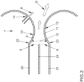
- FIG.2 an outlet area of a preferred second embodiment of a ventilation device 1 according to the invention is shown schematically in a sectional view.
- a blow-out device 14 for blowing out a blow-out air flow A is arranged in an upper area of the air outlet 7 behind the narrowest air outlet cross section Q.
- the blow-out device 14 is designed to blow out the blow-out air flow A in the direction of the total air flow G - or in the direction of the first air flow L1 / the second air flow L2 - formed. By blowing out the exhaust air flow A, the total air flow G is further deflected.
- FIG.3 an outlet area of a preferred third embodiment of a ventilation device 1 according to the invention is shown schematically in a sectional view.
- an intake device 13 for sucking in the total air flow G by means of an intake air flow R is arranged in a lower area of the air outlet 7 behind the narrowest air outlet cross section Q.
- an exhaust device 14 for blowing out an exhaust air flow A is also arranged in an upper area of the air outlet 7 behind the narrowest air outlet cross section Q.
- almost any intake devices 13 and exhaust devices 14 can be arranged on the air outlet 7.
- a deflection device (not shown) can be provided, which is designed both as an intake device 13 and as an exhaust device 14. A preferred position of such a deflection device corresponds to a position of the intake device 13 or exhaust device 14 shown.
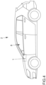
- Fig.4 shows a preferred embodiment of a motor vehicle 2 according to the invention schematically in a side view.
- the motor vehicle 2 has a passenger cell 8 and a ventilation device 1 according to the invention.
Landscapes
- Engineering & Computer Science (AREA)
- Mechanical Engineering (AREA)
- Physics & Mathematics (AREA)
- Thermal Sciences (AREA)
- Chemical & Material Sciences (AREA)
- Combustion & Propulsion (AREA)
- General Engineering & Computer Science (AREA)
- Air-Conditioning For Vehicles (AREA)
- Air-Flow Control Members (AREA)
Description
- Die vorliegende Erfindung betrifft eine Lüftungsvorrichtung für ein Kraftfahrzeug, mittels welcher ein Luftstrom in eine Fahrgastzelle des Kraftfahrzeugs gezielt sowie gerichtet einströmbar ist. Ferner betrifft die vorliegende Erfindung ein Kraftfahrzeug, welches eine erfindungsgemäße Lüftungsvorrichtung aufweist.
- Es sind viele unterschiedliche Lüftungsvorrichtungen zum Belüften von Kraftfahrzeugen bekannt. Besonders verbreitet sind Lüftungsvorrichtungen mit verstellbaren Lamellen zum gezielten Ablenken des Luftstroms. Solche Lüftungsvorrichtungen weisen üblicherweise einen Lüftungskanal mit einem Kanalende sowie einen am Kanalende angeordneten Luftauslass mit einer Mehrzahl von verstellbaren Lamellen auf. Die verstellbaren Lamellen sind oftmals zu einem Teil vertikal und zu einem anderen Teil horizontal ausgerichtet, um den Luftstrom in viele unterschiedliche Richtungen umlenken zu können. Andere bekannte Lüftungsvorrichtungen weisen einen verschwenkbaren Luftauslass mit feststehenden oder auch zusätzlich verschwenkbaren Lamellen auf. Der Luftauslass ist zumindest teilweise kugelförmig ausgebildet, um ein seitliches Ausströmen der Luft am Luftauslass vorbei zu verhindern und um den Luftstrom in viele unterschiedliche Richtungen umlenken zu können. Bei anderen Lüftungsvorrichtungen ist der Luftauslass gemäß einer schwenkbaren Düse ausgebildet, mittels welcher der Luftstrom gebündelt und ebenfalls in mehrere unterschiedliche Richtungen umlenkbar ist.
- Aus der
DE 102 02 926 A1 ist eine Lüftungsvorrichtung für ein Kraftfahrzeug bekannt, welche einen Luftkanal sowie einen Luftauslass aufweist, wobei der Luftkanal mit dem Luftauslass fluidkommunizierend gekoppelt ist. Innerhalb des Luftauslasses sind mehrere um verschiedene Schwenkachsen verschwenkbare Lamellen zum Umlenken eines durch den Luftkanal strömenden Hauptluftstroms angeordnet. Zum Verschwenken der Lamellen weist die Lüftungsvorrichtung einen mit den Lamellen mechanisch gekoppelten Hebel auf, welcher aus dem Luftauslass herausragt. DieDE 10 2015 120 290 A1 offenbart eine Lüftungsvorrichtung für ein Kraftfahrzeug, mit einem Luftkanal sowie einem Luftauslass, wobei der Luftkanal mit dem Luftauslass fluidkommunizierend gekoppelt ist. Innerhalb des Luftauslasses ist eine um eine horizontale Achse schwenkbare Lamelle angeordnet. Durch Verschwenken der Lamelle ist ein durch den Luftkanal strömender Hauptluftstrom umlenkbar. - Die
DE 10 2015 116 242 B3 zeigt eine Lüftungsvorrichtung für ein Kraftfahrzeug, welche einen Hauptlüftungskanal sowie zwei Nebenluftkanäle aufweist, welche allesamt mit einem gemeinsamen Luftkanal fluidkommunizierend gekoppelt sind. Im Bereich vor dem Luftauslass ist der Hauptlüftungskanal gemäß einer Lavaldüse ausgebildet. Mittels einer Ventilvorrichtung ist ein Luftstromanteil der Nebenkanäle beeinflussbar. Luftaustrittsöffnungen der Nebenkanäle sind aufeinander sowie auf den Hauptlüftungskanal gerichtet, sodass durch Beaufschlagen eines Nebenkanals mit einem Nebenluftstrom eine gezielte Ablenkung des Hauptluftstroms bewirkbar ist. - Lüftungsvorrichtungen mit von außen zugänglichen, verstellbaren Lamellen haben den Nachteil, dass im Bereich der Fahrgastzelle bewegliche Teile angeordnet sind, welche durch eine Unachtsamkeit eines Insassen des Kraftfahrzeugs ungewollt verstellt werden können. Ferner sind verstellbare Lamellen nur aufwändig herstellbar sowie montierbar und weisen einen gewissen Verschleiß auf. Lüftungsvorrichtungen mit mehreren Nebenkanälen, deren Luftaustrittsöffnungen aufeinander gerichtet sind, haben den Nachteil, dass diese eine hohe Geräuschentwicklung aufweisen können und somit den Fahrkomfort des Kraftfahrzeugs erheblich mindern können.
- Die Druckschriften
JP S62 228833 A DE 10 2015 109069 A1 undJP H01 98011 U - Es ist Aufgabe der vorliegenden Erfindung, die voranstehend beschriebenen Nachteile bei einer Lüftungsvorrichtung für ein Kraftfahrzeug sowie bei einem Kraftfahrzeug mit einer Lüftungsvorrichtung zu beheben oder zumindest teilweise zu beheben. Es ist insbesondere Aufgabe der vorliegenden Erfindung, eine Lüftungsvorrichtung für ein Kraftfahrzeug und ein Kraftfahrzeug mit einer Lüftungsvorrichtung zu schaffen, die auf eine einfache sowie kostengünstige Art und Weise eine Bereitstellung eines gerichteten Luftstroms in einer Fahrgastzelle des Kraftfahrzeugs gewährleisten und dabei vorzugsweise eine übermäßige Geräuschentwicklung vermeiden.
- Voranstehende Aufgabe wird durch eine Lüftungsvorrichtung mit den Merkmalen des unabhängigen Anspruchs 1 sowie durch ein Kraftfahrzeug mit den Merkmalen des abhängigen Anspruchs 9 gelöst. Vorteilhafte Ausgestaltungen der Erfindung ergeben sich aus den Unteransprüchen.
- Dabei gelten Merkmale und Details, die im Zusammenhang mit der erfindungsgemäßen Lüftungsvorrichtung beschrieben sind, selbstverständlich auch im Zusammenhang mit dem erfindungsgemäßen Kraftfahrzeug. Gemäß einem ersten Aspekt der Erfindung wird die Aufgabe durch eine Lüftungsvorrichtung für ein Kraftfahrzeug mit den Merkmalen des unabhängigen Anspruchs 1 gelöst. Die Lüftungsvorrichtung weist einen ersten Lüftungskanal zum Durchströmen eines ersten Luftstroms, einen vom ersten Lüftungskanal getrennten, zweiten Lüftungskanal zum Durchströmen eines zweiten Luftstroms und einen mit einem ersten Kanalende des ersten Lüftungskanals sowie einem zweiten Kanalende des zweiten Lüftungskanals fluidkommunizierend gekoppelten Luftauslass zum Auslassen eines Gesamtluftstroms in eine Fahrgastzelle des Kraftfahrzeugs auf. Der Gesamtluftstrom weist den ersten Luftstrom und den zweiten Luftstrom auf. Eine erste Luftstromstärke des ersten Luftstroms und eine zweite Luftstromstärke des zweiten Luftstroms sind individuell einstellbar. Erfindungsgemäß weist der Luftauslass in Strömungsrichtung hinter dem ersten Kanalende eine erste Ablenkwand auf, wobei die erste Ablenkwand zum derartigen Ablenken des ersten Luftstroms ausgebildet ist, dass der erste Luftstrom den zweiten Luftstrom kreuzt.
- Der erste Lüftungskanal und der zweite Lüftungskanal sind vorzugsweise als Lüftungskanäle mit jeweils einem nicht verstellbaren Querschnitt ausgebildet. Der erste Lüftungskanal und der zweite Lüftungskanal sind voneinander vorzugsweise derart getrennt, dass ein direkter Luftaustausch zwischen dem ersten Lüftungskanal und dem zweiten Lüftungskanal nicht möglich ist. Vorzugsweise sind der erste Lüftungskanal und der zweite Lüftungskanal durch eine gemeinsame Trennwand voneinander getrennt, wobei die Trennwand vorzugsweise als starre, also nicht verstellbare oder verschwenkbare Trennwand ausgebildet ist. Alternativ zu einer Trennwand kann auch ein dritter Lüftungskanal zwischen dem ersten Lüftungskanal und dem zweiten Lüftungskanal angeordnet sein. Weiter bevorzugt sind der erste Lüftungskanal und der zweite Lüftungskanal parallel zueinander angeordnet, wobei das erste Kanalende und das zweite Kanalende vorzugsweise ebenfalls in dieselbe Richtung weisen. Demnach sind der erste Lüftungskanal und der zweite Lüftungskanal vorzugsweise derart ausgebildet, dass ein das erste Kanalende verlassender erster Luftstrom parallel zu einem das zweite Kanalende verlassenden zweiten Luftstrom strömt. Der erste Lüftungskanal und/oder der zweite Lüftungskanal weisen vorzugsweise einen runden, halbrunden oder ähnlichen Kanalquerschnitt auf. Die Trennwand ist vorzugsweise plattenförmig bzw. flach mit einer länglichen Erstreckung in Strömungsrichtung ausgebildet. Vorzugsweise ist die Lüftungsvorrichtung derart ausgebildet, dass im eingebauten Zustand der erste Lüftungskanal oberhalb des zweiten Lüftungskanals angeordnet ist.
- Der Luftauslass ist in Strömungsrichtung hinter dem ersten Kanalende und dem zweiten Kanalende angeordnet. Der Luftauslass ist ausgebildet, den ersten Luftstrom und den zweiten Luftstrom zu dem Gesamtluftstrom zusammenzuführen. Hierfür weist der Luftauslass erfindungsgemäß in Strömungsrichtung hinter dem ersten Kanalende die erste Ablenkwand auf.
- Die erste Ablenkwand ist vorzugsweise direkt am ersten Kanalende angeordnet und besonders bevorzugt als Fortsetzung einer ersten Kanalwand des ersten Lüftungskanals ausgebildet. Besonders bevorzugt ist die erste Ablenkwand derart an die erste Kanalwand angebunden, dass eine möglichst laminare Anströmung der ersten Ablenkwand gewährleistet ist. Somit ist die erste Ablenkwand vorzugsweise im Bereich der Anbindung an die erste Kanalwand abgerundet ausgebildet und weist demnach eine erste Abrundung auf. Diese erste Abrundung ist vorzugsweise zum zweiten Luftstrom hin ausgebildet. Überdies ist der Luftauslass ausgebildet, den Gesamtluftstrom, welcher den ersten Luftstrom und den zweiten Luftstrom aufweist, in die Fahrgastzelle des Kraftfahrzeugs zu leiten. Der Luftauslass weist vorzugsweise keine beweglichen Bauteile, wie z.B. verschwenkbare oder verdrehbare Flügel, Klappen, Lamellen, Düsen oder dergleichen, auf.
- Die Lüftungsvorrichtung ist ferner ausgebildet, die erste Luftstromstärke des ersten Luftstroms und die zweite Luftstromstärke des zweiten Luftstroms individuell zu steuern. Das bedeutet, dass bei vordefinierter erster Luftstromstärke unterschiedliche zweite Luftstromstärken einstellbar sind. Ebenso sind bei vordefinierter zweiter Luftstromstärke unterschiedliche erste Luftstromstärken einstellbar. Demnach sind die erste Luftstromstärke und die zweite Luftstromstärke im Rahmen der technischen Leistung der Lüftungsvorrichtung im Wesentlichen frei voneinander wählbar. Hierfür kann erfindungsgemäß vorgesehen sein, dass die Lüftungsvorrichtung für den ersten Lüftungskanal und den zweiten Lüftungskanal jeweils eine separate Ventilationsvorrichtung zum Erzeugen eines Luftstroms aufweist, welche separat voneinander ansteuerbar sind. Alternativ kann die Lüftungsvorrichtung eine gemeinsame Ventilationsvorrichtung zum Erzeugen eines Hauptluftstroms aufweisen, welcher auf den ersten Lüftungskanal und den zweiten Lüftungskanal aufteilbar ist.
- Eine erfindungsgemäße Lüftungsvorrichtung hat gegenüber herkömmlichen Lüftungsvorrichtungen den Vorteil, dass mit einfachen Mitteln sowie auf eine kostengünstige Art und Weise ein gerichteter Gesamtluftstrom in der Fahrgastzelle des Kraftfahrzeugs erzeugbar ist, wobei eine Richtung sowie eine Stärke des Gesamtluftstroms durch eine gezielte Steuerung der ersten Luftstromstärke und der zweiten Luftstromstärke steuerbar ist. Bei gleicher erster Luftstromstärke und zweiter Luftstromstärke ist der Gesamtluftstrom parallel zum ersten Lüftungskanal und zweiten Lüftungskanal ausgerichtet. Durch relatives Verändern der ersten Luftstromstärke zur zweiten Luftstromstärke ist der Gesamtluftstrom entsprechend ablenkbar. Wenn der erste Lüftungskanal über dem zweiten Lüftungskanal angeordnet ist, und die erste Luftstromstärke relativ zur zweiten Luftstromstärke erhöht wird, wird der Gesamtluftstrom somit nach unten abgelenkt. Zusätzliche Flügel, Klappen, Lamellen, Düsen oder dergleichen sind demnach nicht erforderlich, sodass Material- sowie Montagekosten einsparbar sind. Überdies ist eine unbeabsichtigte Verstellung der Strömungsrichtung des Gesamtluftstroms somit leicht vermeidbar. Ein weiterer Vorteil der Lüftungsvorrichtung ist, dass durch das Umlenken des ersten Luftstroms hinter dem ersten Kanalende eine Geräuschbildung aufgrund von Strömungsgeräuschen gering ist.
- Gemäß einer bevorzugten Weiterentwicklung der Erfindung kann bei Lüftungsvorrichtungen vorgesehen sein, dass die erste Ablenkwand eine erste Wölbung aufweist, wobei die erste Wölbung in Strömungsrichtung vom zweiten Luftstrom weggerichtet ist. Die erste Wölbung ist vorzugsweise an eine zum zweiten Luftstrom hinweisende Abrundung der ersten Ablenkwand angeschlossen, sodass die erste Ablenkwand zunächst zum zweiten Luftstrom hingeführt ist und sich anschließend von diesem abwendet. Die erste Wölbung weist vorzugsweise einen ersten Wölbungsradius auf, welcher mindestens doppelt so groß, besonders bevorzugt mindestens dreimal so groß, wie ein erster Rundungsradius der ersten Abrundung ausgebildet ist. Auf diese Weise wird eine laminare Strömung des Gesamtluftstroms aus erstem Luftstrom und zweitem Luftstrom mit einfachen Mitteln verbessert. Überdies ist durch die erste Wölbung eine Geräuschbildung aufgrund von Strömungsgeräuschen weiter reduzierbar.
- Es ist erfindungsgemäß bevorzugt, dass der Luftauslass in Strömungsrichtung hinter dem zweiten Kanalende eine zweite Ablenkwand aufweist, wobei die zweite Ablenkwand zum Ablenken des zweiten Luftstroms zum ersten Luftstrom hin ausgebildet ist. Die zweite Ablenkwand ist vorzugsweise direkt am zweiten Kanalende angeordnet und besonders bevorzugt als Fortsetzung einer zweiten Kanalwand des zweiten Lüftungskanals ausgebildet. Besonders bevorzugt ist die zweite Ablenkwand derart an die zweite Kanalwand angebunden, dass eine möglichst laminare Anströmung der zweiten Ablenkwand gewährleistet ist. Somit ist die zweite Ablenkwand vorzugsweise im Bereich der Anbindung an die zweite Kanalwand abgerundet ausgebildet und weist demnach eine zweite Abrundung auf. Diese zweite Abrundung ist vorzugsweise zum ersten Luftstrom hin ausgebildet. Vorzugsweise ist die zweite Ablenkwand spiegelbildlich zur ersten Ablenkwand ausgebildet. Eine zweite Ablenkwand hat den Vorteil, dass eine Zusammenführung des ersten Luftstroms und des zweiten Luftstroms verbessert ist. Zudem wird hierdurch ein Strömungsquerschnitt des Luftauslasses weiter reduziert, sodass eine gezielte Ablenkbarkeit des Gesamtluftstroms bei geringer Geräuschbildung aufgrund von Strömungsgeräuschen mit einfachen Mitteln sowie kostengünstig verbessert ist.
- Weiter bevorzugt weist die zweite Ablenkwand eine zweite Wölbung auf, wobei die zweite Wölbung in Strömungsrichtung vom ersten Luftstrom weggerichtet ist. Die zweite Wölbung ist vorzugsweise an eine zum ersten Luftstrom hinweisende Abrundung der zweiten Ablenkwand angeschlossen, sodass die zweite Ablenkwand zunächst zum ersten Luftstrom hingeführt ist und sich anschließend von diesem abwendet. Die zweite Wölbung weist vorzugsweise einen zweiten Wölbungsradius auf, welcher mindestens doppelt so groß, besonders bevorzugt mindestens dreimal so groß, wie ein zweiter Rundungsradius der zweiten Abrundung ausgebildet ist. Vorzugsweise weist der Luftauslass durch die erste Wölbung und die zweite Wölbung einen Querschnitt gemäß einer Lavaldüse auf. Auf diese Weise wird eine laminare Strömung des Gesamtluftstroms aus erstem Luftstrom und zweitem Luftstrom mit einfachen Mitteln verbessert. Überdies ist durch die zweite Wölbung eine Geräuschbildung aufgrund von Strömungsgeräuschen weiter reduzierbar.
- Erfindungsgemäß ist vorgesehen, dass der Luftauslass eine Ansaugvorrichtung zum Ansaugen des Gesamtluftstroms und/oder eine Ausblasvorrichtung zum Erzeugen eines mit dem Gesamtluftstrom interagierenden Ausblasluftstroms aufweist. Die Ansaugvorrichtung ist in Strömungsrichtung hinter einem engsten Luftauslassquerschnitt des Luftauslasses angeordnet und ist vorzugsweise in Richtung einer Mittelachse des Luftauslasses gerichtet. Somit ist ein effizientes Ansaugen des Gesamtluftstroms mittels eines Ansaugluftstroms verbessert. Die Ausblasvorrichtung ist in Strömungsrichtung hinter dem engsten Luftauslassquerschnitt des Luftauslasses angeordnet und ist vorzugsweise in Richtung der Mittelachse des Luftauslasses gerichtet. Alternativ kann die Ausblasvorrichtung auch von der Mittelachse wegweisen und den Gesamtluftstrom somit mittels des Coanda-Effekts ablenken. Auf diese Weise ist ein effizientes Ablenken des Gesamtluftstroms mittels des Ausblasluftstroms verbessert. Eine Ansaugvorrichtung sowie eine Ausblasvorrichtung haben den Vorteil, dass ein gezieltes Ablenken des Gesamtluftstroms mit einfachen Mitteln sowie kostengünstig verbesserbar ist.
- Vorzugsweise weisen der erste Lüftungskanal einen ersten Kanaleinlass und der zweite Lüftungskanal einen zweiten Kanaleinlass auf, wobei der erste Kanaleinlass und der zweite Kanaleinlass mit einem gemeinsamen Hauptlüftungskanal derart fluidkommunizierend gekoppelt sind, dass ein den Hauptlüftungskanal in Strömungsrichtung durchströmender Hauptluftstrom in den ersten Kanaleinlass und/oder den zweiten Kanaleinlass leitbar ist. Der Hauptlüftungskanal ist vorzugsweise parallel bzw. zumindest in einem Endabschnitt parallel zu dem ersten Lüftungskanal bzw. dem zweiten Lüftungskanal angeordnet. Über den Hauptlüftungskanal ist ein Hauptluftstrom bereitstellbar, welcher auf den ersten Lüftungskanal und den zweiten Lüftungskanal aufteilbar ist. Durch die gezielte Festlegung einer Strömungsgeschwindigkeit des Hauptluftstroms sowie eines Aufteilungsverhältnisses des Hauptluftstroms auf den ersten Lüftungskanal und den zweiten Lüftungskanal sind somit die erste Luftstromstärke sowie die zweite Luftstromstärke auf vorteilhafte Weise sowie mit einfachen Mitteln gezielt einstellbar.
- Es ist zudem bevorzugt, dass die Lüftungsvorrichtung eine Luftstromsteuervorrichtung aufweist, wobei die Luftstromsteuervorrichtung ausgebildet ist, eine Aufteilung des durch den Hauptlüftungskanal strömenden Hauptluftstroms auf den ersten Lüftungskanal und den zweiten Lüftungskanal gezielt zu steuern. Die Luftstromsteuervorrichtung ist vorzugsweise ausgebildet, einen effektiven Strömungsquerschnitt des ersten Kanaleinlasses und des zweiten Kanaleinlasses gezielt einzustellen. Hierfür kann vorgesehen sein, dass die Luftstromsteuervorrichtung beispielsweise ein erstes Steuerventil und ein zweites Steuerventil aufweist, wobei das erste Steuerventil zum Verschließen und Freigeben des ersten Lüftungskanals und das zweite Steuerventil zum Verschließen und Freigeben des zweiten Lüftungskanals ausgebildet sind. Das erste Ventil und das zweite Ventil können unabhängig voneinander ausgebildet oder miteinander mechanisch gekoppelt sein. Eine Luftstromsteuervorrichtung hat den Vorteil, dass hiermit eine gezielte Aufteilung des Hauptluftstroms auf den ersten Lüftungskanal und den zweiten Lüftungskanal verbessert ist.
- Es ist weiter bevorzugt, dass die Luftstromsteuervorrichtung eine bewegliche Klappe zum Aufteilen des Hauptluftstroms auf den ersten Lüftungskanal und den zweiten Lüftungskanal aufweist. Die bewegliche Klappe ist vorzugsweise dem ersten Kanaleinlass und dem zweiten Kanaleinlass benachbart innerhalb des Hauptlüftungskanals angeordnet. Vorzugsweise ist eine Schwenkachse der Klappe an einer den ersten Lüftungskanal und den zweiten Lüftungskanal separierenden Trennwand angeordnet. Ein freies Ende der Klappe ragt vorzugsweise entgegen der Strömungsrichtung in den Hauptlüftungskanal hinein. Mittels der Klappe sind die Strömungsquerschnitte des ersten Kanaleinlasses sowie des zweiten Kanaleinlasses veränderbar und der Hauptluftstrom auf den ersten Lüftungskanal und den zweiten Lüftungskanal gezielt aufteilbar. Vorzugsweise ist die Klappe derart ausgebildet, in einer ersten Extremstellung den ersten Kanaleingang und in einer zweiten Extremstellung den zweiten Kanaleingang vollständig zu verschließen. Es kann erfindungsgemäß vorgesehen sein, dass die Klappe beispielsweise in einem Randbereich eine umlaufende Dichtung aufweist, um ein Abdichten des ersten Kanaleinlasses und des zweiten Kanaleinlasses zu verbessern. Eine Klappe hat den Vorteil, dass mit einfachen Mitteln sowie kostengünstig eine gezielte Aufteilung des Hauptluftstroms auf den ersten Lüftungskanal und den zweiten Lüftungskanal gewährleistet ist.
- Es ist weiter bevorzugt, dass der Luftauslassquerschnitt des Luftauslasses in Strömungsrichtung eine Verjüngung sowie eine Aufweitung aufweist. Vorzugsweise ist der Luftauslassquerschnitt gemäß einer Lavaldüse ausgebildet. Mittels der Verjüngung ist ein effizientes Zusammenführen des ersten Luftstroms und des zweiten Luftstroms verbessert. Durch die Aufweitung ist eine Ablenkung des Gesamtluftstroms verbessert sowie eine Geräuschbildung aufgrund von Strömungsgeräuschen reduziert.
- Gemäß einem zweiten Aspekt der Erfindung wird die Aufgabe durch ein Kraftfahrzeug mit den Merkmalen des abhängigen Anspruchs 9 gelöst.
- Erfindungsgemäß ist die Lüftungsvorrichtung als erfindungsgemäße Lüftungsvorrichtung ausgebildet. Überdies mündet der Luftauslass der Lüftungsvorrichtung in die Fahrgastzelle. Der Luftauslass ist dabei vorzugsweise derart zur Fahrgastzelle angeordnet, dass bei gleicher erster Luftstromstärke und zweiter Luftstromstärke der Gesamtluftstrom in eine Neutralrichtung geleitet wird, wobei diese Neutralrichtung in einer Mitte zwischen einer maximalen oberen bestimmungsgemäßen Gesamtströmungsrichtung und einer maximalen unteren Gesamtströmungsrichtung angeordnet ist.
- Bei dem beschriebenen Kraftfahrzeug ergeben sich sämtliche Vorteile, die bereits zu einer Lüftungsvorrichtung gemäß dem ersten Aspekt der Erfindung beschrieben worden sind. Demnach hat das erfindungsgemäße Kraftfahrzeug gegenüber herkömmlichen Kraftfahrzeugen den Vorteil, dass mit einfachen Mitteln sowie auf eine kostengünstige Art und Weise ein gerichteter Gesamtluftstrom in der Fahrgastzelle des Kraftfahrzeugs erzeugbar ist, wobei eine Richtung sowie eine Stärke des Gesamtluftstroms durch eine gezielte Steuerung der ersten Luftstromstärke und der zweiten Luftstromstärke steuerbar ist. Bei gleicher erster Luftstromstärke und zweiter Luftstromstärke ist der Gesamtluftstrom parallel zum ersten Lüftungskanal und zweiten Lüftungskanal ausgerichtet. Durch relatives Verändern der ersten Luftstromstärke zur zweiten Luftstromstärke ist der Gesamtluftstrom entsprechende ablenkbar. Wenn der erste Lüftungskanal über dem zweiten Lüftungskanal angeordnet ist, und die erste Luftstromstärke relativ zur zweiten Luftstromstärke erhöht wird, wird der Gesamtluftstrom somit nach unten abgelenkt. Zusätzliche Flügel, Klappen, Lamellen, Düsen oder dergleichen sind demnach nicht erforderlich, sodass Material- sowie Montagekosten einsparbar sind. Überdies ist eine unbeabsichtigte Verstellung der Strömungsrichtung des Gesamtluftstroms somit leicht vermeidbar. Ein weiterer Vorteil des erfindungsgemäßen Kraftfahrzeugs ist, dass durch das Umlenken des ersten Luftstroms hinter dem ersten Kanalende eine Geräuschbildung der Lüftungsvorrichtung aufgrund von Strömungsgeräuschen gering ist.
- Eine erfindungsgemäße Lüftungsvorrichtung sowie ein erfindungsgemäßes Kraftfahrzeug werden nachfolgend anhand von Zeichnungen näher erläutert. Es zeigen jeweils schematisch:
- Figur 1
- in einer Schnittdarstellung eine bevorzugte Ausführungsform einer erfindungsgemäßen Lüftungsvorrichtung,
- Figur 2
- in einer Schnittdarstellung einen Auslassbereich einer bevorzugten zweiten Ausführungsform einer erfindungsgemäßen Lüftungsvorrichtung,
- Figur 3
- in einer Schnittdarstellung einen Auslassbereich einer bevorzugten dritten Ausführungsform einer erfindungsgemäßen Lüftungsvorrichtung, und
- Figur 4
- in einer Seitenansicht eine bevorzugte Ausführungsform eines erfindungsgemäßen Kraftfahrzeugs.
- Elemente mit gleicher Funktion und Wirkungsweise sind in den
Fig. 1 bis 4 jeweils mit denselben Bezugszeichen versehen. - In
Fig. 1 ist eine bevorzugte erste Ausführungsform einer erfindungsgemäßen Lüftungsvorrichtung 1 für ein Kraftfahrzeug 2 (vgl.Fig. 4 ) schematisch in einer Schnittdarstellung abgebildet, wobei keine Ansaugvorrichtung (13) und keine Ausblasvorrichtung (14) gezeigt sind. Die Lüftungsvorrichtung 1 weist einen ersten Lüftungskanal 3 mit einem ersten Kanaleinlass 15 sowie einem ersten Kanalende 5 und einen zweiten Lüftungskanal 4 mit einem zweiten Kanaleinlass 16 sowie einem zweiten Kanalende 6 auf. Der erste Lüftungskanal 3 und der zweite Lüftungskanal 4 sind durch eine Trennwand 24 voneinander fluiddicht getrennt. Der erste Lüftungskanal 3 ist in radialer Richtung durch eine erste Kanalwand 20 und der zweite Lüftungskanal 4 durch eine zweite Kanalwand 21 fluiddicht begrenzt. In Strömungsrichtung S ist vor dem ersten Kanaleinlass 15 und dem zweiten Kanaleinlass 16 ein Hauptlüftungskanal 17 ausgebildet. Der Hauptlüftungskanal 17 ist in radialer Richtung durch die erste Kanalwand 20 und die zweite Kanalwand 21 fluiddicht begrenzt. In Strömungsrichtung S auf Höhe des ersten Kanaleinlasses 15 und des zweiten Kanaleinlasses 16 ist eine Luftstromsteuervorrichtung 18 zum gezielten Aufteilen eines durch den Hauptlüftungskanal 17 strömenden Hauptluftstroms H auf den ersten Lüftungskanal 3 und den zweiten Lüftungskanal 4 angeordnet. Die Luftstromsteuervorrichtung 18 weist eine Schwenkvorrichtung 25 und eine an der Schwenkvorrichtung 25 gehaltene Klappe 19 auf. Die Schwenkvorrichtung 25 ist an der Trennwand 24 angeordnet. Die Klappe 19 ragt in den Hauptlüftungskanal 17 hinein. Durch Verschwenken der Klappe 19 um die Schwenkvorrichtung 25 ist der Hauptluftstrom H in einen durch den ersten Lüftungskanal 3 strömenden ersten Luftstrom L1 und einen durch den zweiten Lüftungskanal 4 strömenden zweiten Luftstrom L2 aufteilbar. In dieser Darstellung ist ein von der Schwenkvorrichtung 25 distales Ende der Klappe 19 der zweiten Kanalwand 21 zugewandt, sodass ein größerer Teil des Hauptluftstroms H in den ersten Lüftungskanal 3 und ein kleinerer Teil des Hauptluftstroms H in den zweiten Lüftungskanal 4 strömt. - An dem ersten Kanalende 5 und dem zweiten Kanalende 6 ist ein Luftauslass 7 der Lüftungsvorrichtung 1 angeordnet. Der Luftauslass 7 weist eine erste Ablenkwand 9 auf, die an die erste Kanalwand 20 angebunden ist. Die erste Ablenkwand 9 weist der ersten Kanalwand 20 unmittelbar benachbart eine erste Abrundung 22 auf, welche zum zweiten Luftstrom L2 hin gekrümmt ist. Auf die erste Abrundung 22 folgt in Strömungsrichtung S eine erste Wölbung 10 der ersten Ablenkwand 9, die von dem zweiten Luftstrom L2 weg gekrümmt ist. Die erste Ablenkwand 9 ist somit ausgebildet, den ersten Luftstrom L1 zum zweiten Luftstrom L2 hin abzulenken. Ferner weist der Luftauslass 7 eine zweite Ablenkwand 11 auf, die an die zweite Kanalwand 21 angebunden ist. Die zweite Ablenkwand 11 weist der zweiten Kanalwand 21 unmittelbar benachbart eine zweite Abrundung 23 auf, welche zum ersten Luftstrom L1 hin gekrümmt ist. Auf die zweite Abrundung 23 folgt in Strömungsrichtung S eine zweite Wölbung 12 der zweiten Ablenkwand 11, die von dem ersten Luftstrom L1 weg gekrümmt ist. Die zweite Ablenkwand 11 ist somit ausgebildet, den zweiten Luftstrom L2 zum ersten Luftstrom L1 hin abzulenken. In diesem Ausführungsbeispiel ist der Luftauslass 7 um eine Mittelachse M spiegelsymmetrisch ausgebildet. Ein Luftauslassquerschnitt Q des Luftauslasses 7 verjüngt sich in Strömungsrichtung S vom ersten Kanalende 5 und zweiten Kanalende 6 bis zu einem Minimum und weitet sich anschließend wieder auf. Somit ist der Luftauslass 7 ungefähr gemäß einer Lavaldüse ausgebildet. Im Luftauslass 7 werden der erste Luftstrom L1 und der zweite Luftstrom L2 zu einem Gesamtluftstrom G zusammengeführt.
- In
Fig. 1 ist aufgrund der Stellung der Klappe 19 der erste Luftstrom L1 größer als der zweite Luftstrom L2. Da der erste Luftstrom L1 von der ersten Ablenkwand 9 in dieser Darstellung nach unten abgelenkt wird und stärker als der zweite Luftstrom L2 ausgebildet ist, strömt der den Luftauslass 7 verlassende Gesamtluftstrom G ebenfalls nach unten. Ein weiteres Bewegen der Klappe 19 zur zweiten Kanalwand 21 hin würde einen Anteil des in den ersten Luftkanal 3 strömenden Hauptluftstroms H weiter erhöhen, somit einen Anteil des in den zweiten Lüftungskanal 4 strömenden Hauptluftstroms H entsprechen reduzieren und eine stärkere Ablenkung des Gesamtluftstroms G weiter nach unten bewirken. Ebenso würde ein Bewegen der Klappe 19 zur ersten Kanalwand 20 hin einen Anteil des in den ersten Luftkanal 3 strömenden Hauptluftstroms H reduzieren, somit einen Anteil des in den zweiten Lüftungskanal 4 strömenden Hauptluftstroms H entsprechend erhöhen und eine stärkere Ablenkung des Gesamtluftstroms G weiter nach oben bewirken. - In
Fig. 2 ist ein Auslassbereich einer bevorzugten zweiten Ausführungsform einer erfindungsgemäßen Lüftungsvorrichtung 1 schematisch in einer Schnittdarstellung abgebildet. In dieser zweiten Ausführungsform der erfindungsgemäßen Lüftungsvorrichtung 1 ist in einem oberen Bereich des Luftauslasses 7 hinter dem engsten Luftauslassquerschnitt Q eine Ausblasvorrichtung 14 zum Ausblasen eines Ausblasluftstroms A angeordnet. Die Ausblasvorrichtung 14 ist zum Ausblasen des Ausblasluftstroms A in Richtung des Gesamtluftstroms G - bzw. in Richtung des ersten Luftstroms L1 / des zweiten Luftstroms L2 - ausgebildet. Durch Ausblasen des Ausblasluftstroms A wird der Gesamtluftstrom G weiter abgelenkt. - In
Fig. 3 ist ein Auslassbereich einer bevorzugten dritten Ausführungsform einer erfindungsgemäßen Lüftungsvorrichtung 1 schematisch in einer Schnittdarstellung abgebildet. In dieser dritten Ausführungsform der erfindungsgemäßen Lüftungsvorrichtung 1 ist in einem unteren Bereich des Luftauslasses 7 hinter dem engsten Luftauslassquerschnitt Q eine Ansaugvorrichtung 13 zum Ansaugen des Gesamtluftstroms G mittels eines Ansaugluftstroms R angeordnet. Zudem ist in einem oberen Bereich des Luftauslasses 7 hinter dem engsten Luftauslassquerschnitt Q ebenfalls eine Ausblasvorrichtung 14 zum Ausblasen eines Ausblasluftstroms A angeordnet. Erfindungsgemäß können nahezu beliebig Ansaugvorrichtungen 13 und Ausblasvorrichtungen 14 an dem Luftauslass 7 angeordnet sein. Ferner kann eine nicht dargestellte Ablenkvorrichtung vorgesehen sein, welche sowohl als Ansaugvorrichtung 13 als auch als Ausblasvorrichtung 14 ausgebildet ist. Eine bevorzugte Position einer solchen Ablenkvorrichtung entspricht einer Position der dargestellten Ansaugvorrichtung 13 oder Ausblasvorrichtung 14. -
Fig. 4 zeigt eine bevorzugte Ausführungsform eines erfindungsgemäßen Kraftfahrzeugs 2 schematisch in einer Seitenansicht. Das Kraftfahrzeug 2 weist eine Fahrgastzelle 8 sowie eine erfindungsgemäße Lüftungsvorrichtung 1 auf. -
- 1
- Lüftungsvorrichtung
- 2
- Kraftfahrzeug
- 3
- erster Lüftungskanal
- 4
- zweiter Lüftungskanal
- 5
- erstes Kanalende
- 6
- zweites Kanalende
- 7
- Luftauslass
- 8
- Fahrgastzelle
- 9
- erste Ablenkwand
- 10
- erste Wölbung
- 11
- zweite Ablenkwand
- 12
- zweite Wölbung
- 13
- Ansaugvorrichtung
- 14
- Ausblasvorrichtung
- 15
- erster Kanaleinlass
- 16
- zweiter Kanaleinlass
- 17
- Hauptlüftungskanal
- 18
- Luftstromsteuervorrichtung
- 19
- Klappe
- 20
- erste Kanalwand
- 21
- zweite Kanalwand
- 22
- erste Abrundung
- 23
- zweite Abrundung
- 24
- Trennwand
- 25
- Schwenkvorrichtung
- A
- Ausblasluftstrom
- G
- Gesamtluftstrom
- H
- Hauptluftstrom
- L1
- erster Luftstrom
- L2
- zweiter Luftstrom
- M
- Mittelachse
- Q
- Luftauslassquerschnitt
- R
- Ansaugluftstrom
- S
- Strömungsrichtung
Claims (9)
- Lüftungsvorrichtung (1) für ein Kraftfahrzeug (2), aufweisend einen ersten Lüftungskanal (3) zum Durchströmen eines ersten Luftstroms (L1), einen vom ersten Lüftungskanal (3) getrennten, zweiten Lüftungskanal (4) zum Durchströmen eines zweiten Luftstroms (L2) und einen mit einem ersten Kanalende (5) des ersten Lüftungskanals (3) sowie einem zweiten Kanalende (6) des zweiten Lüftungskanals (4) fluidkommunizierend gekoppelten Luftauslass (7) zum Auslassen eines Gesamtluftstroms (G) in eine Fahrgastzelle (8) des Kraftfahrzeugs (2), wobei der Gesamtluftstrom (G) den ersten Luftstrom (L1) und den zweiten Luftstrom (L2) aufweist, wobei eine erste Luftstromstärke des ersten Luftstroms (L1) und eine zweite Luftstromstärke des zweiten Luftstroms (L2) individuell einstellbar sind,wobei der Luftauslass (7) in Strömungsrichtung (S) hinter dem ersten Kanalende (5) eine erste Ablenkwand (9) aufweist, wobei die erste Ablenkwand (9) zum derartigen Ablenken des ersten Luftstroms (L1) ausgebildet ist, dass der erste Luftstrom (L1) den zweiten Luftstrom (L2) kreuzt,dadurch gekennzeichnet,dass der Luftauslass (7) eine in Strömungsrichtung (S) hinter einem engsten Luftauslassquerschnitt (Q) des Luftauslasses (7) angeordnete Ansaugvorrichtung (13) zum Ansaugen des Gesamtluftstroms (G) und/oder eine in Strömungsrichtung (S) hinter dem engsten Luftauslassquerschnitt (Q) des Luftauslasses (7) angeordnete Ausblasvorrichtung (14) zum Erzeugen eines mit dem Gesamtluftstrom (G) interagierenden Ausblasluftstroms (A) aufweist.
- Lüftungsvorrichtung (1) nach dem vorangehenden Anspruch,
dadurch gekennzeichnet,
dass die erste Ablenkwand (9) eine erste Wölbung (10) aufweist, wobei die erste Wölbung (10) in Strömungsrichtung (S) vom zweiten Luftstrom (L2) weggerichtet ist. - Lüftungsvorrichtung (1) nach einem der vorangehenden Ansprüche,
dadurch gekennzeichnet,
dass der Luftauslass (7) in Strömungsrichtung (S) hinter dem zweiten Kanalende (6) eine zweite Ablenkwand (11) aufweist, wobei die zweite Ablenkwand (11) zum Ablenken des zweiten Luftstroms (L2) zum ersten Luftstrom (L1) hin ausgebildet ist. - Lüftungsvorrichtung (1) nach Anspruch 3,
dadurch gekennzeichnet,
dass die zweite Ablenkwand (11) eine zweite Wölbung (12) aufweist, wobei die zweite Wölbung (12) in Strömungsrichtung (S) vom ersten Luftstrom (L1) weggerichtet ist. - Lüftungsvorrichtung (1) nach einem der vorangehenden Ansprüche,
dadurch gekennzeichnet,
dass der erste Lüftungskanal (3) einen ersten Kanaleinlass (15) und der zweite Lüftungskanal (4) einen zweiten Kanaleinlass (16) aufweisen, wobei der erste Kanaleinlass (15) und der zweite Kanaleinlass (16) mit einem gemeinsamen Hauptlüftungskanal (17) derart fluidkommunizierend gekoppelt sind, dass ein den Hauptlüftungskanal (17) in Strömungsrichtung (S) durchströmender Hauptluftstrom (H) in den ersten Kanaleinlass (15) und/oder in den zweiten Kanaleinlass (16) leitbar ist. - Lüftungsvorrichtung (1) nach Anspruch 5,
dadurch gekennzeichnet,
dass die Lüftungsvorrichtung (1) eine Luftstromsteuervorrichtung (18) aufweist, wobei die Luftstromsteuervorrichtung (18) ausgebildet ist, eine Aufteilung des durch den Hauptlüftungskanal (17) strömenden Hauptluftstroms (H) auf den ersten Lüftungskanal (3) und den zweiten Lüftungskanal (4) gezielt zu steuern. - Lüftungsvorrichtung (1) nach Anspruch 6,
dadurch gekennzeichnet,
dass die Luftstromsteuervorrichtung (18) eine bewegliche Klappe (19) zum Aufteilen des Hauptluftstroms (H) auf den ersten Lüftungskanal (3) und den zweiten Lüftungskanal (4) aufweist. - Lüftungsvorrichtung (1) nach einem der vorangehenden Ansprüche,
dadurch gekennzeichnet,
dass der Luftauslassquerschnitt (Q) des Luftauslasses (7) in Strömungsrichtung (S) eine Verjüngung sowie eine Aufweitung aufweist. - Kraftfahrzeug (2) mit einer Fahrgastzelle (8) und einer Lüftungsvorrichtung (1) zum Belüften der Fahrgastzelle (8),
dadurch gekennzeichnet,
dass die Lüftungsvorrichtung (1) nach einem der vorangehenden Ansprüche ausgebildet ist, wobei der Luftauslass (7) der Lüftungsvorrichtung (1) in die Fahrgastzelle (8) mündet.
Applications Claiming Priority (2)
| Application Number | Priority Date | Filing Date | Title |
|---|---|---|---|
| DE102018203076.6A DE102018203076A1 (de) | 2018-03-01 | 2018-03-01 | Lüftungsvorrichtung und Kraftfahrzeug |
| PCT/EP2019/054050 WO2019166274A1 (de) | 2018-03-01 | 2019-02-19 | Lüftungsvorrichtung für ein kraftfahrzeug |
Publications (2)
| Publication Number | Publication Date |
|---|---|
| EP3758964A1 EP3758964A1 (de) | 2021-01-06 |
| EP3758964B1 true EP3758964B1 (de) | 2024-06-19 |
Family
ID=65529673
Family Applications (1)
| Application Number | Title | Priority Date | Filing Date |
|---|---|---|---|
| EP19707322.4A Active EP3758964B1 (de) | 2018-03-01 | 2019-02-19 | Lüftungsvorrichtung für ein kraftfahrzeug |
Country Status (5)
| Country | Link |
|---|---|
| US (1) | US12391098B2 (de) |
| EP (1) | EP3758964B1 (de) |
| CN (1) | CN112118979A (de) |
| DE (1) | DE102018203076A1 (de) |
| WO (1) | WO2019166274A1 (de) |
Families Citing this family (9)
| Publication number | Priority date | Publication date | Assignee | Title |
|---|---|---|---|---|
| CN113968343A (zh) * | 2020-07-24 | 2022-01-25 | 波音公司 | 送风散流器及其构造方法 |
| KR102923043B1 (ko) * | 2020-08-11 | 2026-02-04 | 현대자동차 주식회사 | 차량용 에어컨 멀티 에어 모드 장치 및 제어 방법 |
| DE102020216529B4 (de) | 2020-12-23 | 2024-01-25 | Volkswagen Aktiengesellschaft | Lüftungsausströmer, Lüftungssystem und Kraftfahrzeug |
| DE102022213321A1 (de) | 2022-12-08 | 2024-06-13 | Volkswagen Aktiengesellschaft | Lüftungsvorrichtung für ein Kraftfahrzeug |
| GB2626004A (en) * | 2023-01-05 | 2024-07-10 | Jaguar Land Rover Ltd | Improvements in vehicle cabin ventilation systems |
| FR3159660B1 (fr) | 2024-02-28 | 2026-01-09 | Stellantis Auto Sas | Aérateur à effet coanda avec une soupape de réduction de pertes de charges |
| DE102024113259A1 (de) * | 2024-05-13 | 2025-11-13 | Illinois Tool Works Inc. | Luftausströmer für ein fahrzeug |
| DE102024117204A1 (de) | 2024-06-19 | 2025-12-24 | Dr. Ing. H.C. F. Porsche Aktiengesellschaft | Luftausströmersystem für ein Kraftfahrzeug |
| DE102024134004A1 (de) * | 2024-11-20 | 2026-05-21 | Audi Aktiengesellschaft | Luftausströmer für ein Kraftfahrzeug und entsprechendes Kraftfahrzeug |
Family Cites Families (18)
| Publication number | Priority date | Publication date | Assignee | Title |
|---|---|---|---|---|
| JPS583177B2 (ja) | 1979-02-06 | 1983-01-20 | 松下電器産業株式会社 | 送風装置の風向変更装置 |
| JPS62228833A (ja) * | 1985-12-12 | 1987-10-07 | Kojima Press Co Ltd | 空調用レジスタ− |
| JPH0198011U (de) | 1987-12-22 | 1989-06-29 | ||
| FR2698588B1 (fr) * | 1992-12-02 | 1995-02-17 | Valeo Thermique Habitacle | Dispositif de chauffage-ventilation et/ou de climatisation pour l'habitacle d'un véhicule automobile. |
| US5762395A (en) * | 1996-06-25 | 1998-06-09 | General Motors Corporation | Molded cross car support structure |
| DE10202926A1 (de) | 2002-01-25 | 2003-07-31 | Opel Adam Ag | Luftdüse |
| EP1878611B1 (de) * | 2006-07-11 | 2009-03-11 | C.R.F. Società Consortile per Azioni | Sitz, insbesondere Fahrzeugsitz, mit Mitteln zur Ablenkung des Ventilationsstroms basierend auf dem Coanda-Effekt |
| JP2014210564A (ja) | 2013-04-05 | 2014-11-13 | 株式会社デンソー | 空気吹出装置 |
| DE102013208944B3 (de) * | 2013-05-15 | 2014-05-15 | Eberspächer Climate Control Systems GmbH & Co. KG | Luftausströmbaugruppe, insbesondere zum Leiten von Luft in einen Fahrzeuginnenraum |
| DE102013210053B3 (de) * | 2013-05-29 | 2014-09-11 | Faurecia Innenraum Systeme Gmbh | Luftausströmer |
| DE102013111175B3 (de) * | 2013-10-09 | 2014-09-04 | Dr. Schneider Kunststoffwerke Gmbh | Luftausströmer |
| JP2016090096A (ja) | 2014-10-31 | 2016-05-23 | 豊和化成株式会社 | 空気吹出装置 |
| US10099536B2 (en) | 2014-12-02 | 2018-10-16 | GM Global Technology Operations LLC | Air vent for a vehicle |
| DE102015109069A1 (de) | 2015-06-09 | 2016-12-15 | Dr. Ing. H.C. F. Porsche Aktiengesellschaft | Belüftungskanal zur Belüftung eines Fahrgastinnenraums eines Kraftfahrzeugs |
| DE102015116242B3 (de) | 2015-09-25 | 2016-09-22 | Dr. Schneider Kunststoffwerke Gmbh | Luftausströmer |
| KR101707617B1 (ko) | 2015-09-30 | 2017-02-21 | 삼성전자주식회사 | 공기 조화기 및 그 제어 방법 |
| DE102016119547A1 (de) | 2016-03-21 | 2017-09-21 | Dr. Schneider Kunststoffwerke Gmbh | Luftausströmer |
| DE102017113906B4 (de) * | 2017-06-23 | 2018-05-09 | Dr. Schneider Kunststoffwerke Gmbh | Luftausströmer |
-
2018
- 2018-03-01 DE DE102018203076.6A patent/DE102018203076A1/de not_active Withdrawn
-
2019
- 2019-02-19 CN CN201980016358.4A patent/CN112118979A/zh active Pending
- 2019-02-19 US US16/977,363 patent/US12391098B2/en active Active
- 2019-02-19 EP EP19707322.4A patent/EP3758964B1/de active Active
- 2019-02-19 WO PCT/EP2019/054050 patent/WO2019166274A1/de not_active Ceased
Also Published As
| Publication number | Publication date |
|---|---|
| DE102018203076A1 (de) | 2019-09-05 |
| US12391098B2 (en) | 2025-08-19 |
| CN112118979A (zh) | 2020-12-22 |
| EP3758964A1 (de) | 2021-01-06 |
| WO2019166274A1 (de) | 2019-09-06 |
| US20210107337A1 (en) | 2021-04-15 |
Similar Documents
| Publication | Publication Date | Title |
|---|---|---|
| WO2019166274A1 (de) | Lüftungsvorrichtung für ein kraftfahrzeug | |
| DE19943822B4 (de) | Strömungsleitanordnung, insbesondere Ausströmgrill für Lüftungs- und Klimaanlagen von Kraftfahrzeugen | |
| DE112017003059B4 (de) | Luftabgabevorrichtung | |
| DE102017120417A1 (de) | Luftausströmer mit einstellbarer Luftaustrittsrichtung, insbesondere Flach- oder Fugenausströmer | |
| EP1902876B1 (de) | Luftführungsgehäuse, insbesondere für eine Kraftfahrzeug-Klimaanlage, mit einer Verteilerklappe und Verfahren zur Regelung einer derartigen Verteilerklappe | |
| DE102009007037A1 (de) | Ausströmdüse einer Belüftungsvorrichtung oder Klimaanlage für Fahrzeuge | |
| DE102006032587B4 (de) | Luftausströmeinrichtung für Fahrzeuge | |
| DE102015109069A1 (de) | Belüftungskanal zur Belüftung eines Fahrgastinnenraums eines Kraftfahrzeugs | |
| DE102010011100A1 (de) | Belüftungseinrichtung für einen Innenraum und Verfahren zum Betreiben einer Belüftungseinrichtung | |
| EP3530506A1 (de) | Luftausströmer | |
| DE102018104048A1 (de) | Luftausströmer | |
| DE102019209011A1 (de) | Lustausströmer | |
| DE10063189B4 (de) | Belüftungsvorrichtung | |
| DE102022111454A1 (de) | Luftausströmer mit einstellbarer Luftaustrittsrichtung, insbesondere Flach- oder Fugenausströmer | |
| DE102006009805A1 (de) | Kabine für Arbeitsfahrzeug | |
| EP2237979B1 (de) | Schalldämpfender fluidkanal mit einem strömungsleitelement | |
| DE602004000754T2 (de) | Auf dem coanda Effekt basierende Luftverteilungsvorrichtung | |
| WO1998057815A1 (de) | Luftstromregulierungsdüse zur belüftung eines kraftfahrzeuginnenraumes | |
| EP1747109B1 (de) | Luftausströmer, insbesondere für ein kraftfahrzeug | |
| DE19854795C1 (de) | Belüftungsvorrichtung für Fahrzeuge | |
| DE102018129562A1 (de) | Luftausströmer für ein fahrzeug sowie belüftungssystem mit einem solchen luftausströmer | |
| DE102023111195B3 (de) | Fahrzeugkonsole für ein Kraftfahrzeug, umfassend einen Luftausströmer, Luftausströmer für eine Fahrzeugkonsole und Kraftfahrzeug mit einer Fahrzeugkonsole | |
| EP3758963A1 (de) | Lüftungsausströmer | |
| DE102019115285A1 (de) | Luftausströmer | |
| DE102019206851A1 (de) | Klimatisierungseinrichtung für ein Kraftfahrzeug, Kraftfahrzeug |
Legal Events
| Date | Code | Title | Description |
|---|---|---|---|
| STAA | Information on the status of an ep patent application or granted ep patent |
Free format text: STATUS: UNKNOWN |
|
| STAA | Information on the status of an ep patent application or granted ep patent |
Free format text: STATUS: THE INTERNATIONAL PUBLICATION HAS BEEN MADE |
|
| PUAI | Public reference made under article 153(3) epc to a published international application that has entered the european phase |
Free format text: ORIGINAL CODE: 0009012 |
|
| STAA | Information on the status of an ep patent application or granted ep patent |
Free format text: STATUS: REQUEST FOR EXAMINATION WAS MADE |
|
| 17P | Request for examination filed |
Effective date: 20201001 |
|
| AK | Designated contracting states |
Kind code of ref document: A1 Designated state(s): AL AT BE BG CH CY CZ DE DK EE ES FI FR GB GR HR HU IE IS IT LI LT LU LV MC MK MT NL NO PL PT RO RS SE SI SK SM TR |
|
| AX | Request for extension of the european patent |
Extension state: BA ME |
|
| DAV | Request for validation of the european patent (deleted) | ||
| DAX | Request for extension of the european patent (deleted) | ||
| STAA | Information on the status of an ep patent application or granted ep patent |
Free format text: STATUS: EXAMINATION IS IN PROGRESS |
|
| 17Q | First examination report despatched |
Effective date: 20220325 |
|
| GRAP | Despatch of communication of intention to grant a patent |
Free format text: ORIGINAL CODE: EPIDOSNIGR1 |
|
| STAA | Information on the status of an ep patent application or granted ep patent |
Free format text: STATUS: GRANT OF PATENT IS INTENDED |
|
| INTG | Intention to grant announced |
Effective date: 20240109 |
|
| GRAS | Grant fee paid |
Free format text: ORIGINAL CODE: EPIDOSNIGR3 |
|
| GRAA | (expected) grant |
Free format text: ORIGINAL CODE: 0009210 |
|
| STAA | Information on the status of an ep patent application or granted ep patent |
Free format text: STATUS: THE PATENT HAS BEEN GRANTED |
|
| AK | Designated contracting states |
Kind code of ref document: B1 Designated state(s): AL AT BE BG CH CY CZ DE DK EE ES FI FR GB GR HR HU IE IS IT LI LT LU LV MC MK MT NL NO PL PT RO RS SE SI SK SM TR |
|
| REG | Reference to a national code |
Ref country code: GB Ref legal event code: FG4D Free format text: NOT ENGLISH |
|
| REG | Reference to a national code |
Ref country code: CH Ref legal event code: EP |
|
| REG | Reference to a national code |
Ref country code: DE Ref legal event code: R096 Ref document number: 502019011476 Country of ref document: DE |
|
| P01 | Opt-out of the competence of the unified patent court (upc) registered |
Free format text: CASE NUMBER: APP_35394/2024 Effective date: 20240612 |
|
| PG25 | Lapsed in a contracting state [announced via postgrant information from national office to epo] |
Ref country code: BG Free format text: LAPSE BECAUSE OF FAILURE TO SUBMIT A TRANSLATION OF THE DESCRIPTION OR TO PAY THE FEE WITHIN THE PRESCRIBED TIME-LIMIT Effective date: 20240619 |
|
| PG25 | Lapsed in a contracting state [announced via postgrant information from national office to epo] |
Ref country code: HR Free format text: LAPSE BECAUSE OF FAILURE TO SUBMIT A TRANSLATION OF THE DESCRIPTION OR TO PAY THE FEE WITHIN THE PRESCRIBED TIME-LIMIT Effective date: 20240619 Ref country code: FI Free format text: LAPSE BECAUSE OF FAILURE TO SUBMIT A TRANSLATION OF THE DESCRIPTION OR TO PAY THE FEE WITHIN THE PRESCRIBED TIME-LIMIT Effective date: 20240619 |
|
| REG | Reference to a national code |
Ref country code: LT Ref legal event code: MG9D |
|
| PG25 | Lapsed in a contracting state [announced via postgrant information from national office to epo] |
Ref country code: GR Free format text: LAPSE BECAUSE OF FAILURE TO SUBMIT A TRANSLATION OF THE DESCRIPTION OR TO PAY THE FEE WITHIN THE PRESCRIBED TIME-LIMIT Effective date: 20240920 |
|
| REG | Reference to a national code |
Ref country code: NL Ref legal event code: MP Effective date: 20240619 |
|
| PG25 | Lapsed in a contracting state [announced via postgrant information from national office to epo] |
Ref country code: LV Free format text: LAPSE BECAUSE OF FAILURE TO SUBMIT A TRANSLATION OF THE DESCRIPTION OR TO PAY THE FEE WITHIN THE PRESCRIBED TIME-LIMIT Effective date: 20240619 |
|
| PG25 | Lapsed in a contracting state [announced via postgrant information from national office to epo] |
Ref country code: NO Free format text: LAPSE BECAUSE OF FAILURE TO SUBMIT A TRANSLATION OF THE DESCRIPTION OR TO PAY THE FEE WITHIN THE PRESCRIBED TIME-LIMIT Effective date: 20240919 Ref country code: LV Free format text: LAPSE BECAUSE OF FAILURE TO SUBMIT A TRANSLATION OF THE DESCRIPTION OR TO PAY THE FEE WITHIN THE PRESCRIBED TIME-LIMIT Effective date: 20240619 Ref country code: HR Free format text: LAPSE BECAUSE OF FAILURE TO SUBMIT A TRANSLATION OF THE DESCRIPTION OR TO PAY THE FEE WITHIN THE PRESCRIBED TIME-LIMIT Effective date: 20240619 Ref country code: GR Free format text: LAPSE BECAUSE OF FAILURE TO SUBMIT A TRANSLATION OF THE DESCRIPTION OR TO PAY THE FEE WITHIN THE PRESCRIBED TIME-LIMIT Effective date: 20240920 Ref country code: FI Free format text: LAPSE BECAUSE OF FAILURE TO SUBMIT A TRANSLATION OF THE DESCRIPTION OR TO PAY THE FEE WITHIN THE PRESCRIBED TIME-LIMIT Effective date: 20240619 Ref country code: BG Free format text: LAPSE BECAUSE OF FAILURE TO SUBMIT A TRANSLATION OF THE DESCRIPTION OR TO PAY THE FEE WITHIN THE PRESCRIBED TIME-LIMIT Effective date: 20240619 Ref country code: RS Free format text: LAPSE BECAUSE OF FAILURE TO SUBMIT A TRANSLATION OF THE DESCRIPTION OR TO PAY THE FEE WITHIN THE PRESCRIBED TIME-LIMIT Effective date: 20240919 |
|
| PG25 | Lapsed in a contracting state [announced via postgrant information from national office to epo] |
Ref country code: NL Free format text: LAPSE BECAUSE OF FAILURE TO SUBMIT A TRANSLATION OF THE DESCRIPTION OR TO PAY THE FEE WITHIN THE PRESCRIBED TIME-LIMIT Effective date: 20240619 |
|
| PG25 | Lapsed in a contracting state [announced via postgrant information from national office to epo] |
Ref country code: NL Free format text: LAPSE BECAUSE OF FAILURE TO SUBMIT A TRANSLATION OF THE DESCRIPTION OR TO PAY THE FEE WITHIN THE PRESCRIBED TIME-LIMIT Effective date: 20240619 |
|
| PG25 | Lapsed in a contracting state [announced via postgrant information from national office to epo] |
Ref country code: PT Free format text: LAPSE BECAUSE OF FAILURE TO SUBMIT A TRANSLATION OF THE DESCRIPTION OR TO PAY THE FEE WITHIN THE PRESCRIBED TIME-LIMIT Effective date: 20241021 |
|
| PG25 | Lapsed in a contracting state [announced via postgrant information from national office to epo] |
Ref country code: PT Free format text: LAPSE BECAUSE OF FAILURE TO SUBMIT A TRANSLATION OF THE DESCRIPTION OR TO PAY THE FEE WITHIN THE PRESCRIBED TIME-LIMIT Effective date: 20241021 |
|
| PG25 | Lapsed in a contracting state [announced via postgrant information from national office to epo] |
Ref country code: PL Free format text: LAPSE BECAUSE OF FAILURE TO SUBMIT A TRANSLATION OF THE DESCRIPTION OR TO PAY THE FEE WITHIN THE PRESCRIBED TIME-LIMIT Effective date: 20240619 |
|
| PG25 | Lapsed in a contracting state [announced via postgrant information from national office to epo] |
Ref country code: EE Free format text: LAPSE BECAUSE OF FAILURE TO SUBMIT A TRANSLATION OF THE DESCRIPTION OR TO PAY THE FEE WITHIN THE PRESCRIBED TIME-LIMIT Effective date: 20240619 |
|
| PG25 | Lapsed in a contracting state [announced via postgrant information from national office to epo] |
Ref country code: IS Free format text: LAPSE BECAUSE OF FAILURE TO SUBMIT A TRANSLATION OF THE DESCRIPTION OR TO PAY THE FEE WITHIN THE PRESCRIBED TIME-LIMIT Effective date: 20241019 |
|
| PG25 | Lapsed in a contracting state [announced via postgrant information from national office to epo] |
Ref country code: CZ Free format text: LAPSE BECAUSE OF FAILURE TO SUBMIT A TRANSLATION OF THE DESCRIPTION OR TO PAY THE FEE WITHIN THE PRESCRIBED TIME-LIMIT Effective date: 20240619 |
|
| PG25 | Lapsed in a contracting state [announced via postgrant information from national office to epo] |
Ref country code: RO Free format text: LAPSE BECAUSE OF FAILURE TO SUBMIT A TRANSLATION OF THE DESCRIPTION OR TO PAY THE FEE WITHIN THE PRESCRIBED TIME-LIMIT Effective date: 20240619 Ref country code: SK Free format text: LAPSE BECAUSE OF FAILURE TO SUBMIT A TRANSLATION OF THE DESCRIPTION OR TO PAY THE FEE WITHIN THE PRESCRIBED TIME-LIMIT Effective date: 20240619 |
|
| PG25 | Lapsed in a contracting state [announced via postgrant information from national office to epo] |
Ref country code: SM Free format text: LAPSE BECAUSE OF FAILURE TO SUBMIT A TRANSLATION OF THE DESCRIPTION OR TO PAY THE FEE WITHIN THE PRESCRIBED TIME-LIMIT Effective date: 20240619 Ref country code: ES Free format text: LAPSE BECAUSE OF FAILURE TO SUBMIT A TRANSLATION OF THE DESCRIPTION OR TO PAY THE FEE WITHIN THE PRESCRIBED TIME-LIMIT Effective date: 20240619 |
|
| PG25 | Lapsed in a contracting state [announced via postgrant information from national office to epo] |
Ref country code: SM Free format text: LAPSE BECAUSE OF FAILURE TO SUBMIT A TRANSLATION OF THE DESCRIPTION OR TO PAY THE FEE WITHIN THE PRESCRIBED TIME-LIMIT Effective date: 20240619 Ref country code: SK Free format text: LAPSE BECAUSE OF FAILURE TO SUBMIT A TRANSLATION OF THE DESCRIPTION OR TO PAY THE FEE WITHIN THE PRESCRIBED TIME-LIMIT Effective date: 20240619 Ref country code: RO Free format text: LAPSE BECAUSE OF FAILURE TO SUBMIT A TRANSLATION OF THE DESCRIPTION OR TO PAY THE FEE WITHIN THE PRESCRIBED TIME-LIMIT Effective date: 20240619 Ref country code: PL Free format text: LAPSE BECAUSE OF FAILURE TO SUBMIT A TRANSLATION OF THE DESCRIPTION OR TO PAY THE FEE WITHIN THE PRESCRIBED TIME-LIMIT Effective date: 20240619 Ref country code: IS Free format text: LAPSE BECAUSE OF FAILURE TO SUBMIT A TRANSLATION OF THE DESCRIPTION OR TO PAY THE FEE WITHIN THE PRESCRIBED TIME-LIMIT Effective date: 20241019 Ref country code: ES Free format text: LAPSE BECAUSE OF FAILURE TO SUBMIT A TRANSLATION OF THE DESCRIPTION OR TO PAY THE FEE WITHIN THE PRESCRIBED TIME-LIMIT Effective date: 20240619 Ref country code: EE Free format text: LAPSE BECAUSE OF FAILURE TO SUBMIT A TRANSLATION OF THE DESCRIPTION OR TO PAY THE FEE WITHIN THE PRESCRIBED TIME-LIMIT Effective date: 20240619 Ref country code: CZ Free format text: LAPSE BECAUSE OF FAILURE TO SUBMIT A TRANSLATION OF THE DESCRIPTION OR TO PAY THE FEE WITHIN THE PRESCRIBED TIME-LIMIT Effective date: 20240619 |
|
| PG25 | Lapsed in a contracting state [announced via postgrant information from national office to epo] |
Ref country code: IT Free format text: LAPSE BECAUSE OF FAILURE TO SUBMIT A TRANSLATION OF THE DESCRIPTION OR TO PAY THE FEE WITHIN THE PRESCRIBED TIME-LIMIT Effective date: 20240619 |
|
| REG | Reference to a national code |
Ref country code: DE Ref legal event code: R097 Ref document number: 502019011476 Country of ref document: DE |
|
| PG25 | Lapsed in a contracting state [announced via postgrant information from national office to epo] |
Ref country code: DK Free format text: LAPSE BECAUSE OF FAILURE TO SUBMIT A TRANSLATION OF THE DESCRIPTION OR TO PAY THE FEE WITHIN THE PRESCRIBED TIME-LIMIT Effective date: 20240619 |
|
| PLBE | No opposition filed within time limit |
Free format text: ORIGINAL CODE: 0009261 |
|
| STAA | Information on the status of an ep patent application or granted ep patent |
Free format text: STATUS: NO OPPOSITION FILED WITHIN TIME LIMIT |
|
| 26N | No opposition filed |
Effective date: 20250320 |
|
| PG25 | Lapsed in a contracting state [announced via postgrant information from national office to epo] |
Ref country code: SE Free format text: LAPSE BECAUSE OF FAILURE TO SUBMIT A TRANSLATION OF THE DESCRIPTION OR TO PAY THE FEE WITHIN THE PRESCRIBED TIME-LIMIT Effective date: 20240619 |
|
| PG25 | Lapsed in a contracting state [announced via postgrant information from national office to epo] |
Ref country code: MC Free format text: LAPSE BECAUSE OF FAILURE TO SUBMIT A TRANSLATION OF THE DESCRIPTION OR TO PAY THE FEE WITHIN THE PRESCRIBED TIME-LIMIT Effective date: 20240619 |
|
| REG | Reference to a national code |
Ref country code: CH Ref legal event code: PL |
|
| PG25 | Lapsed in a contracting state [announced via postgrant information from national office to epo] |
Ref country code: LU Free format text: LAPSE BECAUSE OF NON-PAYMENT OF DUE FEES Effective date: 20250219 |
|
| PG25 | Lapsed in a contracting state [announced via postgrant information from national office to epo] |
Ref country code: CH Free format text: LAPSE BECAUSE OF NON-PAYMENT OF DUE FEES Effective date: 20250228 |
|
| GBPC | Gb: european patent ceased through non-payment of renewal fee |
Effective date: 20250219 |
|
| REG | Reference to a national code |
Ref country code: BE Ref legal event code: MM Effective date: 20250228 |
|
| PG25 | Lapsed in a contracting state [announced via postgrant information from national office to epo] |
Ref country code: GB Free format text: LAPSE BECAUSE OF NON-PAYMENT OF DUE FEES Effective date: 20250219 |
|
| PG25 | Lapsed in a contracting state [announced via postgrant information from national office to epo] |
Ref country code: BE Free format text: LAPSE BECAUSE OF NON-PAYMENT OF DUE FEES Effective date: 20250228 |
|
| PG25 | Lapsed in a contracting state [announced via postgrant information from national office to epo] |
Ref country code: IE Free format text: LAPSE BECAUSE OF NON-PAYMENT OF DUE FEES Effective date: 20250219 |
|
| PGFP | Annual fee paid to national office [announced via postgrant information from national office to epo] |
Ref country code: DE Payment date: 20260228 Year of fee payment: 8 |
|
| PG25 | Lapsed in a contracting state [announced via postgrant information from national office to epo] |
Ref country code: AT Free format text: LAPSE BECAUSE OF NON-PAYMENT OF DUE FEES Effective date: 20250219 |
|
| REG | Reference to a national code |
Ref country code: AT Ref legal event code: MM01 Ref document number: 1695716 Country of ref document: AT Kind code of ref document: T Effective date: 20250219 |
|
| PGFP | Annual fee paid to national office [announced via postgrant information from national office to epo] |
Ref country code: FR Payment date: 20260224 Year of fee payment: 8 |