EP3758963B1 - Lüftungsausströmer - Google Patents
Lüftungsausströmer Download PDFInfo
- Publication number
- EP3758963B1 EP3758963B1 EP19707315.8A EP19707315A EP3758963B1 EP 3758963 B1 EP3758963 B1 EP 3758963B1 EP 19707315 A EP19707315 A EP 19707315A EP 3758963 B1 EP3758963 B1 EP 3758963B1
- Authority
- EP
- European Patent Office
- Prior art keywords
- air
- lamella
- slat
- ventilation
- guiding
- Prior art date
- Legal status (The legal status is an assumption and is not a legal conclusion. Google has not performed a legal analysis and makes no representation as to the accuracy of the status listed.)
- Active
Links
Images



Classifications
-
- B—PERFORMING OPERATIONS; TRANSPORTING
- B60—VEHICLES IN GENERAL
- B60H—ARRANGEMENTS OF HEATING, COOLING, VENTILATING OR OTHER AIR-TREATING DEVICES SPECIALLY ADAPTED FOR PASSENGER OR GOODS SPACES OF VEHICLES
- B60H1/00—Heating, cooling or ventilating devices
- B60H1/34—Nozzles; Air-diffusers
- B60H1/3414—Nozzles; Air-diffusers with means for adjusting the air stream direction
-
- B—PERFORMING OPERATIONS; TRANSPORTING
- B60—VEHICLES IN GENERAL
- B60H—ARRANGEMENTS OF HEATING, COOLING, VENTILATING OR OTHER AIR-TREATING DEVICES SPECIALLY ADAPTED FOR PASSENGER OR GOODS SPACES OF VEHICLES
- B60H1/00—Heating, cooling or ventilating devices
- B60H1/34—Nozzles; Air-diffusers
- B60H1/3414—Nozzles; Air-diffusers with means for adjusting the air stream direction
- B60H1/3421—Nozzles; Air-diffusers with means for adjusting the air stream direction using only pivoting shutters
-
- F—MECHANICAL ENGINEERING; LIGHTING; HEATING; WEAPONS; BLASTING
- F24—HEATING; RANGES; VENTILATING
- F24F—AIR-CONDITIONING; AIR-HUMIDIFICATION; VENTILATION; USE OF AIR CURRENTS FOR SCREENING
- F24F13/00—Details common to, or for air-conditioning, air-humidification, ventilation or use of air currents for screening
- F24F13/08—Air-flow control members, e.g. louvres, grilles, flaps or guide plates
- F24F13/10—Air-flow control members, e.g. louvres, grilles, flaps or guide plates movable, e.g. dampers
- F24F13/14—Air-flow control members, e.g. louvres, grilles, flaps or guide plates movable, e.g. dampers built up of tilting members, e.g. louvre
- F24F13/1413—Air-flow control members, e.g. louvres, grilles, flaps or guide plates movable, e.g. dampers built up of tilting members, e.g. louvre using more than one tilting member, e.g. with several pivoting blades
Definitions
- the present invention relates to a ventilation outlet for a ventilation system of a motor vehicle for the directed flow of air into a passenger compartment of the motor vehicle with an air flow flowing in a flow direction.
- the invention further relates to a ventilation system for ventilating a passenger compartment of a motor vehicle and a motor vehicle with a ventilation system.
- Ventilation systems for motor vehicles have ventilation outlets for the targeted directing of an air flow to a passenger compartment.
- Many different ventilation outlets for ventilation systems are known, which differ in their basic principle, their tasks and their functions.
- ventilation outlets that have rigid air guide slats, via which the air flow can be directed in a constant direction.
- Such ventilation outlets are used, for example, to direct air flow to the window panes of the motor vehicle, since the relative position of the window pane to the ventilation outlet is constant and thus a variable deflection of the air flow is not necessary.
- Other ventilation outlets which are intended in particular for directing the air flow in the direction of the occupants of the motor vehicle - so-called passenger vents - have an adjustable deflection device for variably deflecting the air flow.
- Such a deflection device can, for example, have adjustable or pivotable slats.
- a ventilation outlet for a ventilation system of a motor vehicle in which several air guide slats are mechanically coupled to one another for synchronous pivoting.
- the air guide slat can be pivoted using an operating handle arranged on an air guide slat.
- Such a ventilation outlet has the disadvantage that an unintentional adjustment of the air guide slats is easily possible due to unintentional contact between a passenger in the motor vehicle and an air guide slat. From the EN 10 2012 015 748 A1 , JP 2013 086633 A ,
- the EP 3 321 113 A1 which was published after the claimed priority date of the present invention and is not relevant to the question of inventive step, discloses an air vent having an air duct in which at least one first slat is pivotably arranged, wherein the air duct has an air outlet opening, and at least one deflection element is arranged parallel to the at least one first slat on the opposite sides of the air duct.
- the object of the present invention is to eliminate the above-described disadvantages in a ventilation outlet for a ventilation system of a motor vehicle, a ventilation system for ventilating a passenger compartment of a motor vehicle and a motor vehicle with a ventilation system.
- the object of the present invention is to create a ventilation outlet for a ventilation system of a motor vehicle, a ventilation system for ventilating a passenger compartment of a motor vehicle and a motor vehicle, which can ensure the directed flow of the passenger compartment of the motor vehicle with an air flow flowing in one flow direction in a simple and cost-effective manner.
- a ventilation vent for a ventilation system of a motor vehicle for the directed flow of air into a passenger compartment of the motor vehicle with an air flow flowing in a flow direction with the features of independent claim 1, by a ventilation system for ventilating a passenger compartment of a motor vehicle with the features of dependent claim 6 and by a motor vehicle with the features of dependent claim 7.
- Advantageous embodiments of the invention emerge from the subclaims.
- a ventilation vent for a ventilation system of a motor vehicle for the directed flow of an air flow flowing in a flow direction to a passenger compartment of the motor vehicle with the features of independent claim 1.
- the ventilation vent has a housing, a cover device and a first air guide slat.
- the cover device has a first cover section and a second cover section, wherein a slot-shaped air gap is formed between the first cover section and the second cover section.
- the first air guide slat has a first front slat end in the flow direction and a first rear slat end, wherein the first air guide slat is held pivotably about a first pivot axis relative to the cover device.
- a slat width of the first air guide slat extends parallel to the air gap.
- the first air guide slat is in the flow direction arranged in alignment in front of the first panel section.
- a first shielding blade is arranged at the first front blade end, which extends in a direction facing away from the air gap and is designed to shield a blade side of the first air guide blade facing away from the air gap from the air flow.
- the first shielding blade is curved, with a radius of curvature of the curvature of the first shielding blade being defined by the first pivot axis.
- the ventilation outlet further comprises a second air guide blade with a second front blade end in the flow direction and a second rear slat end, wherein the second air guide slat is held pivotably about a second pivot axis relative to the panel device.
- a slat width of the second air guide slat extends parallel to the air gap.
- the second air guide slat is arranged in alignment in the flow direction in front of the second panel section.
- the first air guide slat and the second air guide slat are mechanically coupled to one another in such a way that pivoting of the first air guide slat causes pivoting of the second air guide slat.
- a ventilation system of a motor vehicle is a device for providing at least one air flow in the passenger compartment of the motor vehicle.
- the ventilation system usually has a blower device for generating an air flow in a ventilation duct of the ventilation system.
- the ventilation outlet can be arranged at an interface between the ventilation system and the passenger compartment at a free end of the ventilation duct in order to direct the air flow flowing out of the ventilation duct to the passenger compartment.
- the housing of the ventilation outlet can preferably be arranged at the free end of the ventilation duct, in particular in a sealing manner. It can also be provided that the housing is designed as a ventilation duct or at least as a ventilation duct segment. Preferably, the first air guide slat - and/or any second air guide slat present - is pivotably held on the housing. Within the scope of the invention, the housing can also be formed entirely or partially by the cover device.
- a flow direction is understood to be a direction in which the air flow flows. Inside the ventilation duct, the flow direction follows the course of the ventilation duct. The direction of flow of the air flow can be specifically changed by the ventilation outlet, so that it leaves the ventilation outlet at a definable, variable angle and enters the passenger compartment.
- the diaphragm device has the first diaphragm section and the second diaphragm section.
- the air gap through which the air flow can flow is defined by the first diaphragm section and the second diaphragm section.
- the diaphragm device is preferably designed as a passive component and thus has no movable, in particular no pivotable, components. A variable deflection of the air flow in different directions is preferably not possible by means of the diaphragm device.
- the diaphragm device is preferably designed to define an air gap with a rectangular cross-section, wherein the cross-section preferably has a cross-sectional width which is at least twice as large, preferably at least three times as large, and particularly preferably at least four times as large as a cross-sectional height of the cross section. Accordingly, the air gap preferably has a substantially horizontal extension.
- the cover device On the sides facing away from the air gap, the cover device preferably has a connecting section for connecting the ventilation outlet to an instrument panel, a center console, a roof liner, a door or side panel, a pillar panel or the like.
- the first air guide slat is preferably plate-shaped with a slat width, a slat thickness and a slat depth.
- the slat width and the slat depth are preferably significantly greater than the slat thickness.
- the slat depth is preferably at least three times, preferably at least four times, the slat thickness.
- the slat depth is limited by the first front slat end and the first rear slat end.
- the first front slat end points away from the diaphragm device, against the direction of flow.
- the first front slat end is designed as the free end of the air guide slat.
- the first rear slat end faces the first diaphragm section and is arranged adjacent to it or is connected to the first diaphragm section.
- the first air guide slat has a first pivot axis about which the first air guide slat can be pivoted relative to the diaphragm device.
- the first pivot axis is preferably arranged parallel to the cross-sectional width of the air gap.
- the slat width corresponds at least substantially to the cross-sectional width of the air gap, so that the air flow flowing through the air gap can be directed as effectively as possible.
- the first air guide slat preferably comprises a metal and/or a plastic, preferably with reinforcing fibers, in particular with glass fibers, carbon fibers and/or aramid fibers.
- a preferred slat width of the first air guide slat is approximately 200 mm with a cross-sectional width of the air gap of also approximately 200 mm.
- the first air guide slat is coupled to a spring device in such a way that unintentional adjustment of the first air guide slat due to a flow strength of the air flow is prevented.
- the spring device is preferably designed and arranged in such a way that unintentional adjustment of the first air guide slat, in particular in the event of impacts, such as due to bumps or a rough road surface, can be prevented by means of the spring device.
- This is particularly advantageous when the first air guide slat is deflected from a stable equilibrium position and therefore a restoring force in the direction of the stable equilibrium position already acts on the first air guide slat.
- the spring device therefore preferably counteracts such a restoring force.
- the first air guide slat is arranged in the flow direction in front of the first panel section, so that an air flow flowing in the flow direction first first air guide slat and after the first air guide slat the first panel section.
- an aligned arrangement is understood to mean that the first air guide slat at least partially shields the first panel section in such a way that a direct flow of the air flow onto the first panel section can be prevented or at least partially prevented.
- the first air guide slat is designed, for example, as a horizontal slat.
- a horizontal slat is arranged approximately parallel to the vehicle floor of the motor vehicle.
- the ventilation vent according to the invention can have at least one vertical slat, which is arranged in front of the first air guide slat in the direction of flow.
- the at least one vertical slat is preferably arranged particularly close, in particular as close as technically possible, in front of the first air guide slat in the direction of flow, without limiting the functionality of the at least one vertical slat or the first air guide slat.
- the at least one vertical slat can be pivoted about a vertical pivot axis and is designed to guide the air flow in different horizontal directions. It is also preferred that the at least one vertical slat is designed to close the ventilation duct, for example by being positioned transversely relative to the air flow. The closing of the ventilation duct is particularly preferably provided in conjunction with at least one further vertical slat. In this way, a size of the air mass flow can be regulated or changed by means of the at least one vertical slat.
- the vertical slat has a preferred slat width of approximately 40 mm or of at least approximately one fifth of a slat width of the first air guide slat.
- the vertical slat preferably comprises a plastic.
- the first shielding slat is arranged at the first front slat end, which extends in the direction facing away from the air gap and is designed to shield the slat side of the first air guide slat facing away from the air gap from the air flow.
- a second shielding slat is arranged at the second front slat end, which extends in the direction facing away from the air gap and is designed to shield the slat side of the second air guide slat facing away from the air gap from the air flow.
- An area between the first front slat end and the ventilation duct can be covered by means of the first shielding slat.
- the first shielding slat is preferably designed in such a way that the area is also shielded when the first air guide slat is adjusted.
- the first shielding slat is curved.
- the radius of curvature of the curvature of the first shielding slat is defined by the first pivot axis.
- the second shielding slat is preferably corresponding to the first shielding louvre.
- Such a first shielding louvre or second shielding louvre has the advantage that the air flow can be better deflected towards the air gap even when the air guide louvres are in unfavourable positions and the occurrence of turbulence in the area of the cover sections can be reduced. Another positive effect is reduced noise emissions.
- the ventilation outlet further comprises a second air guide slat with a second front slat end in the direction of flow and a second rear slat end, wherein the second air guide slat is held pivotably about a second pivot axis relative to the panel device.
- a slat width of the second air guide slat extends parallel to the air gap.
- the second air guide slat is arranged in alignment in front of the second panel section in the direction of flow.
- the second air guide slat is preferably designed in accordance with the first air guide slat.
- the first air guide slat is designed as a lower air guide slat, which delimits a lower region of the air gap cross-section
- the second air guide slat is designed as an upper air guide slat, which delimits an upper region of the air gap cross-section.
- At least one central, in particular pivotable, air guide slat can also be provided, which is arranged within the air gap cross-section.
- the second pivot axis preferably runs parallel to the air gap, in particular horizontally.
- the second air guide slat preferably comprises a plastic, preferably with reinforcing fibers, in particular glass fibers, carbon fibers and/or aramid fibers, and/or a metal.
- a preferred slat width of the second air guide slat preferably corresponds to the slat width of the first air guide slat.
- a second air guide slat has the advantage that a better deflection of the air flow can be achieved using simple means and at low cost. Furthermore, a direct flow onto the second panel section can thus be prevented.
- the first air guide slat and the second air guide slat are mechanically coupled to one another in such a way that pivoting the first air guide slat causes pivoting of the second air guide slat.
- the first air guide slat and the second air guide slat are connected to one another, for example by means of a coupling device, such as a coupling rod.
- the coupling device is preferably arranged on one side of the air duct in order to avoid disrupting the air flow.
- Such a mechanical coupling has the advantage that setting the desired flow direction of the air flow, which it should have after leaving the ventilation outlet, is improved using simple means and at low cost.
- a ventilation outlet according to the invention has the advantage over conventional ventilation outlets that it can be installed using simple means and in a cost-effective manner. and an air flow flowing out of the ventilation duct can be deflected, the movable parts of the ventilation outlet, in particular the first air guide slat, being arranged behind the cover device when viewed from the passenger compartment and thus protected from external influences. The risk of unintentional adjustment of the air guide slats is thus significantly reduced compared to conventional ventilation outlets.
- the first air guide slat in a ventilation vent, can be arranged on the first cover section in such a way that at least 50% of a slat thickness of the first air guide slat at the first rear slat end is covered by the first cover section.
- the first slat end of the first air guide slat is arranged on the cover device in such a way that, viewed from the passenger compartment, a maximum of 50% of the slat thickness of the first air guide slat can be seen at the first rear slat end and the rest of the first rear slat end is covered by the first cover section.
- the first cover section preferably covers a larger part of the slat thickness of the second air guide slat. Covering it in this way has the advantage that the first air guide slat is better protected from external influences than the passenger compartment by means of the cover device.
- the first air guide slat is arranged on the first panel section in such a way that the first rear slat end is completely covered by the first panel section, at least in sections along the first pivot axis.
- the first rear slat end is also preferably completely covered by the first panel section.
- the first rear slat end is preferably arranged on the first panel section in such a way that the first panel section does not represent an obstacle to the air flow, so that a laminar air flow is promoted or a laminar air flow is prevented from breaking off. Covering it in this way has the advantage that the first air guide slat is better protected from external influences by the panel device compared to the passenger compartment.
- the second air guide slat is arranged on the second cover section in such a way that at least 50% of a slat thickness of the second air guide slat at the second rear slat end is covered by the second cover section.
- the second slat end of the second air guide slat is arranged on the cover device in such a way that, viewed from the passenger compartment, a maximum of 50% of the slat thickness of the second air guide slat is visible at the second rear slat end and the rest of the second rear slat end is covered by the second cover section.
- the second cover section covers a larger part of the slat thickness the second air guide slat. Covering it in this way has the advantage that the second air guide slat is better protected from external influences by means of the cover device compared to the passenger compartment.
- the second air guide slat is further preferably arranged on the second panel section in such a way that the second rear slat end is completely covered by the second panel section, at least in sections along the second pivot axis.
- the second rear slat end is further preferably completely covered by the second panel section.
- the second rear slat end is preferably arranged on the second panel section in such a way that the second panel section does not represent an obstacle to the air flow, so that a laminar air flow is promoted or a laminar air flow is prevented from breaking off. Covering it in this way has the advantage that the second air guide slat is better protected from external influences by the panel device compared to the passenger compartment.
- the object is achieved by a ventilation system for ventilating a passenger compartment of a motor vehicle with the features of the dependent claim 6.
- the ventilation system has a blower device for generating an air flow flowing in a flow direction, a ventilation duct for guiding the air flow and a ventilation outlet for directing the air flow towards the passenger compartment of the motor vehicle.
- the ventilation outlet is designed as a ventilation outlet according to the invention.
- the blower device is preferably designed in accordance with a conventional blower device with a drive motor and a fan impeller, for example as an axial fan, tangential fan or the like.
- the ventilation duct is coupled to the blower device in a fluid-communicating manner to forward the air flow generated by the blower device and has a front ventilation duct end and a rear ventilation duct end in the direction of flow.
- the ventilation system has a heating device for heating the air flow and/or a cooling device for cooling the air flow.
- the ventilation outlet according to the invention is arranged in a fluid-communicating manner at the rear ventilation duct end of the ventilation duct and is preferably sealed therewith in order to prevent lateral outflow past the housing of the ventilation outlet.
- the cover device of the ventilation outlet faces away from the ventilation duct.
- the ventilation system described offers all the advantages that have already been described for a ventilation outlet according to the first aspect of the invention. Accordingly, the ventilation system according to the invention has advantages over conventional Ventilation systems have the advantage that an air flow flowing out of the ventilation duct can be diverted using simple means and in a cost-effective manner, with the moving parts of the ventilation outlet, in particular the first air guide slat, being arranged behind the cover device when viewed from the passenger compartment and thus protected from external influences. The risk of the air guide slats being accidentally adjusted is thus significantly reduced compared to conventional ventilation systems.
- the object is achieved by a motor vehicle with a ventilation system having the features of dependent claim 7.
- the ventilation system is designed according to a ventilation system according to the invention.
- the motor vehicle described offers all the advantages that have already been described for a ventilation outlet according to the first aspect of the invention and for a ventilation system according to the invention according to the second aspect of the invention. Accordingly, the motor vehicle according to the invention has the advantage over conventional motor vehicles that an air flow flowing out of the ventilation duct can be deflected using simple means and in a cost-effective manner, with the movable parts of the ventilation outlet, in particular the first air guide slat, being arranged behind the cover device when viewed from the passenger compartment and thus protected from external influences. The risk of unintentional adjustment of the air guide slats is thus significantly reduced compared to conventional motor vehicles.
- FIG.1 A preferred embodiment of a ventilation vent 1 according to the invention is shown schematically in a perspective view.
- the ventilation vent 1 has a housing 5 and a diaphragm device 6 with a lower first diaphragm section 7 and an upper second diaphragm section 8. Between the first diaphragm section 7 and the second diaphragm section 8 there is an air gap 9 for passing through an air flow L (cf. Fig.3 ). Air guide slats are not or hardly visible in this view.
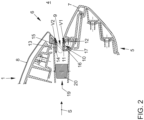
- FIG.2 is the preferred embodiment of the ventilation outlet 1 according to the invention
- Fig.1 shown schematically in a sectional view.
- the air gap 9 formed between the first aperture section 7 and the second aperture section 8 of the aperture device 6 is clearly visible.
- a first air guide slat 10 is arranged in the flow direction S in front of the first aperture section 7 such that a first rear slat end 12 faces the first aperture section 7 and is arranged adjacent to it.
- a first front slat end 11 of the first air guide slat 10 points away from the aperture device 6 against the flow direction S.
- a second air guide slat 13 is arranged in the flow direction S in front of the second aperture section 8 such that a second rear slat end 15 faces the second aperture section 8 and is arranged adjacent to it.
- a second front slat end 14 of the second air guide slat 13 points away from the cover device 6 against the flow direction S.
- the first air guide slat 10 is held at the first rear slat end 12 so that it can pivot about a first pivot axis V1 relative to the cover device 6.
- the second air guide slat 13 is held at the second rear slat end 15 so that it can pivot about a second pivot axis V2 relative to the cover device 6.
- a first shielding slat 16 is arranged at the first front slat end 11 for shielding a slat side 17 facing away from the air gap 9.
- a vertical slat 20 for redirecting the air flow L (cf. Fig.3 ) in the horizontal direction.
- an end region of a ventilation duct 19 for passing the air flow L to the ventilation outlet 1 and if necessary, for subsequent entry into a passenger compartment 4 is shown schematically.
- Fig.3 shows the preferred embodiment of the ventilation outlet 1 according to the invention Fig.1 with a first air guide slat position schematically in a perspective view.
- the first air guide slat 10 and the second air guide slat 13 are arranged horizontally in the first slat position, so that the air flow L flowing in the flow direction S is deflected to the first panel section 7 due to the geometric design of the ventilation outlet 1.
- the first shielding slat 16 prevents the air flow L from flowing onto the opposite slat side 17 of the first air guide slat 10.
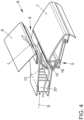
- Fig.4 shows the preferred embodiment of the ventilation outlet 1 according to the invention Fig.1 with a second air guide slat position, schematically in a perspective view.
- the first air guide slat 10 and the second air guide slat 13 are set upwards in the flow direction S in the second slat position, so that the air flow L flowing in the flow direction S is deflected to the second cover section 8.
- the first shielding slat 16 is accommodated in a free space of the housing 5.
- the first air guide slat 10 prevents the air flow L from flowing onto the opposite slat side 17 of the first air guide slat 10.
- a preferred embodiment of a ventilation system 2 according to the invention is shown schematically in a side view.
- the ventilation system 2 has a blower device 18 for generating an air flow L.
- a ventilation duct 19 for passing the air flow L in the flow direction S is arranged on the blower device 18 in a fluid-communicating manner.
- a ventilation outlet 1 according to the invention for discharging and directing the air flow L is arranged at an end of the ventilation duct 19 remote from the blower device 18.
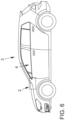
- Fig.6 shows a preferred embodiment of a motor vehicle 3 according to the invention schematically in a side view.
- the motor vehicle 3 has a ventilation system 2 according to the invention for ventilating a passenger cell 4 of the motor vehicle 3.
Landscapes
- Engineering & Computer Science (AREA)
- Mechanical Engineering (AREA)
- Physics & Mathematics (AREA)
- Thermal Sciences (AREA)
- Chemical & Material Sciences (AREA)
- Combustion & Propulsion (AREA)
- General Engineering & Computer Science (AREA)
- Air-Conditioning For Vehicles (AREA)
Description
- Die vorliegende Erfindung betrifft einen Lüftungsausströmer für ein Lüftungssystem eines Kraftfahrzeugs zum gerichteten Anströmen einer Fahrgastzelle des Kraftfahrzeugs mit einem in eine Strömungsrichtung strömenden Luftstrom. Ferner betrifft die Erfindung ein Lüftungssystem zum Belüften einer Fahrgastzelle eines Kraftfahrzeugs sowie ein Kraftfahrzeug mit einem Lüftungssystem.
- Zum gezielten Lenken eines Luftstroms zum gerichteten Anströmen einer Fahrgastzelle weisen Lüftungssysteme für Kraftfahrzeuge Lüftungsausströmer auf. Es sind viele unterschiedliche Lüftungsausströmer für Lüftungssysteme bekannt, die sich in ihrem Grundprinzip, ihren Aufgaben und ihren Funktionen unterscheiden. Es gibt beispielsweise Lüftungsausströmer, die starre Luftleitlamellen aufweisen, über welche der Luftstrom in eine konstante Richtung leitbar ist. Derartige Lüftungsausströmer kommen beispielsweise zum Anströmen von Fensterscheiben des Kraftfahrzeugs zum Einsatz, da eine relative Lage von Fensterscheibe zum Lüftungsausströmer konstant ist und somit eine variable Umlenkung des Luftstroms nicht erforderlich ist. Andere Lüftungsausströmer, die insbesondere zum Lenken des Luftstroms in Richtung der Insassen des Kraftfahrzeugs vorgesehen sind - sogenannte Personenausströmer-, weisen eine verstellbare Ablenkvorrichtung zum variablen Ablenken des Luftstroms auf. Eine solche Ablenkvorrichtung kann beispielsweise verstellbare bzw. verschwenkbare Lamellen aufweisen.
- Aus der
DE 10 2004 062 935 B4 ist beispielsweise ein Lüftungsausströmer für ein Lüftungssystem eines Kraftfahrzeugs bekannt, bei welchem mehrere Luftleitlamellen zum synchronen Verschwenken miteinander mechanisch gekoppelt sind. Über eine an einer Luftleitlamelle angeordnete Bedienungshandhabe ist die Luftleitlamelle verschwenkbar. Ein derartiger Lüftungsausströmer hat den Nachteil, dass ein ungewolltes Verstellen der Luftleitlamellen durch unbeabsichtigten Kontakt eines Insassen des Kraftfahrzeugs mit einer Luftleitlamelle leicht möglich ist. Aus denDE 10 2012 015 748 A1 ,JP 2013 086633 A -
DE 10 2015 120 290 A1 undUS 2006/223430 A1 sind weitere unterschiedliche Lüftungsvorrichtungen bekannt. DieEP 3 321 113 A1 , die nach dem beanspruchten Prioritätsdatum der vorliegenden Erfindung veröffentlicht worden und für die Frage der erfinderischen Tätigkeit nicht von Bedeutung ist, offenbart ein Luftausströmer, der einen Luftkanal aufweist, in dem mindestens eine erste Lamelle verschwenkbar angeordnet ist, wobei der Luftkanal eine Luftaustrittsöffnung aufweist, und parallel zu der mindestens einen ersten Lamelle an den gegenüberliegenden Seiten des Luftkanals jeweils mindestens ein Ablenkelement angeordnet ist. - Es ist Aufgabe der vorliegenden Erfindung, die voranstehend beschriebenen Nachteile bei einem Lüftungsausströmer für ein Lüftungssystem eines Kraftfahrzeugs, einem Lüftungssystem zum Belüften einer Fahrgastzelle eines Kraftfahrzeugs sowie einem Kraftfahrzeug mit einem Lüftungssystem zu beheben oder zumindest teilweise zu beheben. Insbesondere ist es Aufgabe der vorliegenden Erfindung, einen Lüftungsausströmer für ein Lüftungssystem eines Kraftfahrzeugs, ein Lüftungssystem zum Belüften einer Fahrgastzelle eines Kraftfahrzeugs sowie ein Kraftfahrzeug zu schaffen, die auf eine einfache und kostengünstige Art und Weise das gerichtete Anströmen der Fahrgastzelle des Kraftfahrzeugs mit einem in eine Strömungsrichtung strömenden Luftstrom gewährleisten können.
- Voranstehende Aufgabe wird durch einen Lüftungsausströmer für ein Lüftungssystem eines Kraftfahrzeugs zum gerichteten Anströmen einer Fahrgastzelle des Kraftfahrzeugs mit einem in eine Strömungsrichtung strömenden Luftstrom mit den Merkmalen des unabhängigen Anspruchs 1, durch ein Lüftungssystem zum Belüften einer Fahrgastzelle eines Kraftfahrzeugs mit den Merkmalen des abhängigen Anspruchs 6 sowie durch ein Kraftfahrzeug mit den Merkmalen des abhängigen Anspruchs 7 gelöst. Vorteilhafte Ausgestaltungen der Erfindung ergeben sich aus den Unteransprüchen. Dabei gelten Merkmale und Details, die im Zusammenhang mit dem erfindungsgemäßen Lüftungsausströmer beschrieben sind, selbstverständlich auch im Zusammenhang mit dem erfindungsgemäßen Lüftungssystem sowie mit dem erfindungsgemäßen Kraftfahrzeug.
- Gemäß einem ersten Aspekt der Erfindung wird die Aufgabe durch einen Lüftungsausströmer für ein Lüftungssystem eines Kraftfahrzeugs zum gerichteten Anströmen einer Fahrgastzelle des Kraftfahrzeugs mit einem in eine Strömungsrichtung strömenden Luftstrom mit den Merkmalen des unabhängigen Anspruchs 1 gelöst. Der Lüftungsausströmer weist ein Gehäuse, eine Blendenvorrichtung sowie eine erste Luftleitlamelle auf. Die Blendenvorrichtung weist einen ersten Blendenabschnitt und einen zweiten Blendenabschnitt auf, wobei zwischen dem ersten Blendenabschnitt und dem zweiten Blendenabschnitt ein schlitzförmiger Luftspalt ausgebildet ist. Die erste Luftleitlamelle weist ein in Strömungsrichtung erstes vorderes Lamellenende und ein erstes hinteres Lamellenende auf, wobei die erste Luftleitlamelle um eine erste Verschwenkachse verschwenkbar relativ zur Blendenvorrichtung gehalten ist. Eine Lamellenbreite der ersten Luftleitlamelle erstreckt sich parallel zum Luftspalt. Erfindungsgemäß ist die erste Luftleitlamelle in Strömungsrichtung fluchtend vor dem ersten Blendenabschnitt angeordnet. Am ersten vorderen Lamellenende ist eine erste Abschirmlamelle angeordnet, welche sich in eine vom Luftspalt abgewandte Richtung erstreckt und zum Abschirmen einer dem Luftspalt abgewandten Lamellenseite der ersten Luftleitlamelle vom Luftstrom ausgebildet ist. Die erste Abschirmlamelle ist gekrümmt ausgebildet, wobei ein Krümmungsradius der Krümmung der ersten Abschirmlamelle durch die erste Verschwenkachse definiert ist. Der Lüftungsausströmer weist ferner eine zweite Luftleitlamelle mit einem in Strömungsrichtung zweiten vorderen Lamellenende und einem zweiten hinteren Lamellenende auf, wobei die zweite Luftleitlamelle um eine zweite Verschwenkachse verschwenkbar relativ zur Blendenvorrichtung gehalten ist. Eine Lamellenbreite der zweiten Luftleitlamelle erstreckt sich parallel zum Luftspalt. Die zweite Luftleitlamelle ist in Strömungsrichtung fluchtend vor dem zweiten Blendenabschnitt angeordnet. Überdies sind die erste Luftleitlamelle und die zweite Luftleitlamelle derart miteinander mechanisch gekoppelt, dass ein Verschwenken der ersten Luftleitlamelle ein Verschwenken der zweiten Luftleitlamelle bewirkt.
- Ein Lüftungssystem eines Kraftfahrzeugs ist eine Vorrichtung zum Bereitstellen mindestens eines Luftstroms in der Fahrgastzelle des Kraftfahrzeugs. Das Lüftungssystem weist üblicherweise eine Gebläsevorrichtung zum Erzeugen eines Luftstroms in einem Lüftungskanal des Lüftungssystems auf. Der Lüftungsausströmer ist an einer Schnittstelle des Lüftungssystems zur Fahrgastzelle an einem freien Ende des Lüftungskanals anordenbar, um den aus dem Lüftungskanal strömenden Luftstrom zum gerichteten Anströmen der Fahrgastzelle zu lenken.
- Das Gehäuse des Lüftungsausströmers ist vorzugsweise an dem freien Ende des Lüftungskanals, insbesondere abdichtend, anordenbar. Es kann auch vorgesehen sein, dass das Gehäuse als Lüftungskanal oder zumindest als Lüftungskanalsegment ausgebildet ist. Vorzugsweise ist die erste Luftleitlamelle - und/oder eine etwaig vorhandene zweite Luftleitlamelle - am Gehäuse schwenkbar gehalten. Das Gehäuse kann im Rahmen der Erfindung auch ganz oder teilweise durch die Blendenvorrichtung gebildet sein.
- Unter einer Strömungsrichtung wird eine Richtung verstanden, in welche der Luftstrom strömt. Im Inneren des Lüftungskanals folgt die Strömungsrichtung einem Verlauf des Lüftungskanals. Durch den Lüftungsausströmer ist die Strömungsrichtung des Luftstroms gezielt veränderbar, sodass dieser unter einem bestimmbaren variablen Winkel den Lüftungsausströmer verlässt und in die Fahrgastzelle eintritt.
- Die Blendenvorrichtung weist den ersten Blendenabschnitt und den zweiten Blendenabschnitt auf. Durch den ersten Blendenabschnitt und den zweiten Blendenabschnitt ist der Luftspalt festgelegt, durch welchen der Luftstrom strömbar ist. Die Blendenvorrichtung ist vorzugsweise als Passivbauteil ausgebildet und weist somit keine beweglichen, insbesondere keine verschwenkbaren, Bauelemente auf. Ein variables Umlenken des Luftstroms in unterschiedliche Richtungen ist mittels der Blendenvorrichtung vorzugsweise nicht möglich. Die Blendenvorrichtung ist vorzugsweise derart ausgebildet, einen Luftspalt mit einem rechteckigen Querschnitt zu definieren, wobei der Querschnitt vorzugsweise eine Querschnittsbreite aufweist, welche mindestens doppelt so groß, vorzugsweise mindestens dreimal so groß, und besonders bevorzugt mindestens viermal so groß, wie eine Querschnittshöhe des Querschnitts ausgebildet ist. Demnach weist der Luftspalt vorzugsweise eine im Wesentlichen horizontale Erstreckung auf. Auf dem Luftspalt abgewandten Seiten weist die Blendenvorrichtung vorzugsweise einen Anbindungsabschnitt zum Anbinden des Lüftungsausströmers an eine Instrumententafel, eine Mittelkonsole, einen Dachhimmel, eine Tür- oder Seitenverkleidung, eine Säulenverkleidung oder dergleichen auf.
- Die erste Luftleitlamelle ist vorzugsweise plattenförmig mit einer Lamellenbreite, einer Lamellendicke sowie einer Lamellentiefe ausgebildet. Die Lamellenbreite und die Lamellentiefe sind dabei vorzugsweise wesentlich größer als die Lamellendicke. Vorzugsweise beträgt die Lamellentiefe mindestens das Dreifache, vorzugsweise mindestens das Vierfache, der Lamellendicke. Die Lamellentiefe ist durch das erste vordere Lamellenende und das erste hintere Lamellenende begrenzt. Das erste vordere Lamellenende weist von der Blendenvorrichtung weg, der Strömungsrichtung entgegen. Das erste vordere Lamellenende ist als freies Ende der Luftleitlamelle ausgebildet. Das erste hintere Lamellenende ist dem ersten Blendenabschnitt zugewandt sowie dieser benachbart angeordnet oder an den ersten Blendenabschnitt angebunden. Am ersten hinteren Lamellenende weist die erste Luftleitlamelle eine erste Verschwenkachse auf, um welche die erste Luftleitlamelle relativ zur Blendenvorrichtung verschwenkbar ist. Die erste Verschwenkachse ist vorzugsweise parallel zur Querschnittsbreite des Luftspalts angeordnet. Vorzugsweise entspricht die Lamellenbreite der Querschnittsbreite des Luftspalts zumindest im Wesentlichen, sodass der durch den Luftspalt strömende Luftstrom möglichst effektiv lenkbar ist. Die erste Luftleitlamelle weist vorzugsweise ein Metall und/oder einen Kunststoff, vorzugsweise mit Verstärkungsfasern, insbesondere mit Glasfasern, Kohlefasern und/oder Aramidfasern, auf. Eine bevorzugte Lamellenbreite der ersten Luftleitlamelle beträgt etwa 200 mm bei einer Querschnittsbreite des Luftspalts von ebenfalls etwa 200 mm. Weiter bevorzugt ist die erste Luftleitlamelle mit einer Federvorrichtung derart gekoppelt, dass ein unbeabsichtigtes Verstellen der ersten Luftleitlamelle aufgrund einer Strömungsstärke des Luftstroms verhindert wird. Zudem ist die Federvorrichtung vorzugsweise derart ausgebildet und angeordnet, dass eine ungewollte Verstellung der ersten Luftleitlamelle, insbesondere bei Stößen, wie z. B. aufgrund von Bodenwellen oder einem rauen Fahrbahnbelag, mittels der Federvorrichtung verhinderbar ist. Dies ist insbesondere von Vorteil, wenn die erste Luftleitlamelle aus einer stabilen Gleichgewichtslage ausgelenkt ist und daher bereits eine Rückstellkraft in Richtung der stabilen Gleichgewichtslage auf die erste Luftleitlamelle wirkt. Die Federvorrichtung wirkt daher vorzugsweise einer solchen Rückstellkraft entgegen.
- Erfindungsgemäß ist die erste Luftleitlamelle in Strömungsrichtung vor dem ersten Blendenabschnitt angeordnet, sodass ein in Strömungsrichtung strömender Luftstrom zuerst die erste Luftleitlamelle und nach der ersten Luftleitlamelle den ersten Blendenabschnitt anströmt. Unter einer fluchtenden Anordnung wird im Rahmen der Erfindung verstanden, dass die erste Luftleitlamelle den ersten Blendenabschnitt zumindest teilweise derart abschirmt, dass hierdurch ein direktes Anströmen des ersten Blendenabschnitts durch den Luftstrom verhinderbar bzw. zumindest teilweise verhinderbar ist.
- Die erste Luftleitlamelle ist beispielsweise als Horizontallamelle ausgebildet. Eine Horizontallamelle ist im eingebauten Zustand des Lüftungsausströmers etwa parallel zum Fahrzeugboden des Kraftfahrzeugs angeordnet. Zudem kann der erfindungsgemäße Lüftungsausströmer mindestens eine Vertikallamelle aufweisen, welche in Strömungsrichtung vor der ersten Luftleitlamelle angeordnet ist. Zum Erzielen einer besonders genauen Ablenkbarkeit des Luftstroms ist die mindestens eine Vertikallamelle vorzugsweise besonders nah, insbesondere so nah wie technisch möglich, in Strömungsrichtung vor der ersten Luftleitlamelle angeordnet, ohne dabei eine Funktionalität der mindestens einen Vertikallamelle bzw. der ersten Luftleitlamelle zu beschränken. Die mindestens eine Vertikallamelle ist um eine vertikale Verschwenkachse verschwenkbar und zum Leiten des Luftstroms in unterschiedliche horizontale Richtungen ausgebildet. Ferner ist es bevorzugt, dass die mindestens eine Vertikallamelle ausgebildet ist, den Lüftungskanal zu verschließen, beispielsweise durch ein Querstellen relativ zum Luftstrom. Besonders bevorzugt ist das Verschließen des Lüftungskanals im Zusammenspiel mit mindestens einer weiteren Vertikallamelle vorgesehen. Auf diese Weise ist eine Größe des Luftmassenstroms mittels der mindestens einen Vertikallamelle regulierbar bzw. veränderbar. Die Vertikallamelle weist eine bevorzugte Lamellenbreite von etwa 40 mm oder von zumindest etwa einem Fünftel einer Lamellenbreite der ersten Luftleitlamelle auf. Zudem weist die Vertikallamelle vorzugsweise einen Kunststoff auf.
- Am ersten vorderen Lamellenende ist die erste Abschirmlamelle angeordnet, welche sich in die vom Luftspalt abgewandte Richtung erstreckt und zum Abschirmen der dem Luftspalt abgewandten Lamellenseite der ersten Luftleitlamelle vom Luftstrom ausgebildet ist. Zusätzlich kann erfindungsgemäß vorgesehen sein, dass am zweiten vorderen Lamellenende eine zweite Abschirmlamelle angeordnet ist, welche sich in die vom Luftspalt abgewandte Richtung erstreckt und zum Abschirmen der dem Luftspalt abgewandten Lamellenseite der zweiten Luftleitlamelle vom Luftstrom ausgebildet ist. Mittels der ersten Abschirmlamelle ist ein Bereich zwischen dem ersten vorderen Lamellenende und dem Lüftungskanal abdeckbar. Die erste Abschirmlamelle ist vorzugsweise derart ausgebildet, dass der Bereich auch beim Verstellen der ersten Luftleitlamelle abgeschirmt wird. Die erste Abschirmlamelle ist gekrümmt ausgebildet. Der Krümmungsradius der Krümmung der ersten Abschirmlamelle ist durch die erste Verschwenkachse definiert. Die zweite Abschirmlamelle ist vorzugsweise entsprechend der ersten Abschirmlamelle ausgebildet. Eine derartige erste Abschirmlamelle bzw. zweite Abschirmlamelle hat den Vorteil, dass der Luftstrom auch bei ungünstigen Stellungen der Luftleitlamellen besser zum Luftspalt hin ablenkbar und das Entstehen von Turbulenzen im Bereich der Blendenabschnitte reduzierbar ist. Ein weiterer positiver Effekt ist eine reduzierte Geräuschemission.
- Ferner weist der Lüftungsausströmer eine zweite Luftleitlamelle mit einem in Strömungsrichtung zweiten vorderen Lamellenende und einem zweiten hinteren Lamellenende auf, wobei die zweite Luftleitlamelle um eine zweite Verschwenkachse verschwenkbar relativ zur Blendenvorrichtung gehalten ist. Eine Lamellenbreite der zweiten Luftleitlamelle erstreckt sich parallel zum Luftspalt. Die zweite Luftleitlamelle ist in Strömungsrichtung fluchtend vor dem zweiten Blendenabschnitt angeordnet. Die zweite Luftleitlamelle ist vorzugsweise gemäß der ersten Luftleitlamelle ausgebildet. Vorzugsweise ist die erste Luftleitlamelle als untere Luftleitlamelle, welche einen unteren Bereich des Luftspaltquerschnitts begrenzt, und die zweite Luftleitlamelle als obere Luftleitlamelle ausgebildet, welche einen oberen Bereich des Luftspaltquerschnitts begrenzt. Es kann noch mindestens eine zentrale, insbesondere verschwenkbare, Luftleitlamelle vorgesehen sein, welche innerhalb des Luftspaltquerschnitts angeordnet ist. Die zweite Verschwenkachse verläuft vorzugsweise parallel zum Luftspalt, insbesondere horizontal. Die zweite Luftleitlamelle weist vorzugsweise einen Kunststoff, bevorzugt mit Verstärkungsfasern, insbesondere Glasfasern, Kohlefasern und/oder Aramidfasern, und/oder ein Metall auf. Eine bevorzugte Lamellenbreite der zweiten Luftleitlamelle entspricht vorzugsweise der Lamellenbreite der ersten Luftleitlamelle. Eine zweite Luftleitlamelle hat den Vorteil, dass mit einfachen Mitteln sowie kostengünstig eine bessere Umlenkung des Luftstroms bewirkbar ist. Ferner kann somit ein direktes Anströmen des zweiten Blendenabschnitts verhindert werden.
- Die erste Luftleitlamelle und die zweite Luftleitlamelle sind derart miteinander mechanisch gekoppelt, dass ein Verschwenken der ersten Luftleitlamelle ein Verschwenken der zweiten Luftleitlamelle bewirkt. Hierfür sind die erste Luftleitlamelle und die zweite Luftleitlamelle beispielsweise mittels einer Koppelvorrichtung, wie z. B. einer Koppelstange, miteinander verbunden. Die Koppelvorrichtung ist vorzugsweise an einer Seite des Luftkanals angeordnet, um ein Stören des Luftstroms zu vermeiden. Eine derartige mechanische Kopplung hat den Vorteil, dass ein Einstellen der gewünschten Strömungsrichtung des Luftstroms, welche dieser nach Verlassen des Lüftungsausströmers aufweisen soll, mit einfachen Mitteln sowie kostengünstig verbessert ist.
- Ein erfindungsgemäßer Lüftungsausströmer hat gegenüber herkömmlichen Lüftungsausströmern den Vorteil, dass mit einfachen Mitteln sowie auf eine kostengünstige Art und Weise ein aus dem Lüftungskanal strömender Luftstrom ablenkbar ist, wobei die beweglichen Teile des Lüftungsausströmers, insbesondere die erste Luftleitlamelle, von der Fahrgastzelle aus betrachtet hinter der Blendenvorrichtung angeordnet und somit vor äußeren Einflüssen geschützt ist. Die Gefahr eines unbeabsichtigten Verstellens der Luftleitlamellen ist somit gegenüber herkömmlichen Lüftungsausströmern erheblich reduziert.
- Gemäß einer bevorzugten Weiterentwicklung der Erfindung kann bei einem Lüftungsausströmer vorgesehen sein, dass die erste Luftleitlamelle derart an dem ersten Blendenabschnitt angeordnet ist, dass mindestens 50% einer Lamellendicke der ersten Luftleitlamelle am ersten hinteren Lamellenende vom ersten Blendenabschnitt verdeckt ist. Mit anderen Worten ist das erste Lamellenende der ersten Luftleitlamelle derart an der Blendenvorrichtung angeordnet, dass von der Fahrgastzelle aus betrachtet maximal 50% der Lamellendicke der ersten Luftleitlamelle am ersten hinteren Lamellenende erkennbar sind und der Rest des ersten hinteren Lamellenendes von dem ersten Blendenabschnitt verdeckt ist. Vorzugsweise verdeckt der erste Blendenabschnitt einen größeren Teil der Lamellendicke der zweiten Luftleitlamelle. Ein derartiges Verdecken hat den Vorteil, dass die erste Luftleitlamelle mittels der Blendenvorrichtung gegenüber der Fahrgastzelle besser vor äußeren Einflüssen geschützt ist.
- Es ist erfindungsgemäß bevorzugt, dass die erste Luftleitlamelle derart an dem ersten Blendenabschnitt angeordnet ist, dass das erste hintere Lamellenende vom ersten Blendenabschnitt zumindest abschnittsweise entlang der ersten Verschwenkachse vollständig verdeckt ist. Weiter bevorzugt ist das erste hintere Lamellenende komplett vom ersten Blendenabschnitt verdeckt. Dabei ist das erste hintere Lamellenende vorzugsweise derart am ersten Blendenabschnitt angeordnet, dass der erste Blendenabschnitt kein Hindernis für den Luftstrom darstellt, sodass ein laminarer Luftstrom begünstigt bzw. ein Abreißen eines laminaren Luftstroms verhindert wird. Ein derartiges Verdecken hat den Vorteil, dass die erste Luftleitlamelle mittels der Blendenvorrichtung gegenüber der Fahrgastzelle besser vor äußeren Einflüssen geschützt ist.
- In einer besonders bevorzugten Ausgestaltung der Erfindung kann bei einem Lüftungsausströmer vorgesehen sein, dass die zweite Luftleitlamelle derart an dem zweiten Blendenabschnitt angeordnet ist, dass mindestens 50% einer Lamellendicke der zweiten Luftleitlamelle am zweiten hinteren Lamellenende vom zweiten Blendenabschnitt verdeckt ist. Mit anderen Worten ist das zweite Lamellenende der zweiten Luftleitlamelle derart an der Blendenvorrichtung angeordnet, dass von der Fahrgastzelle aus betrachtet maximal 50% der Lamellendicke der zweiten Luftleitlamelle am zweiten hinteren Lamellenende erkennbar sind und der Rest des zweiten hinteren Lamellenendes von dem zweiten Blendenabschnitt verdeckt ist. Vorzugsweise verdeckt der zweite Blendenabschnitt einen größeren Teil der Lamellendicke der zweiten Luftleitlamelle. Ein derartiges Verdecken hat den Vorteil, dass die zweite Luftleitlamelle mittels der Blendenvorrichtung gegenüber der Fahrgastzelle besser vor äußeren Einflüssen geschützt ist.
- Weiter bevorzugt ist die zweite Luftleitlamelle derart an dem zweiten Blendenabschnitt angeordnet, dass das zweite hintere Lamellenende vom zweiten Blendenabschnitt zumindest abschnittsweise entlang der zweiten Verschwenkachse vollständig verdeckt ist. Weiter bevorzugt ist das zweite hintere Lamellenende komplett vom zweiten Blendenabschnitt verdeckt. Dabei ist das zweite hintere Lamellenende vorzugsweise derart am zweiten Blendenabschnitt angeordnet, dass der zweite Blendenabschnitt kein Hindernis für den Luftstrom darstellt, sodass ein laminarer Luftstrom begünstigt bzw. ein Abreißen eines laminaren Luftstroms verhindert wird. Ein derartiges Verdecken hat den Vorteil, dass die zweite Luftleitlamelle mittels der Blendenvorrichtung gegenüber der Fahrgastzelle besser vor äußeren Einflüssen geschützt ist.
- Gemäß einem zweiten Aspekt der Erfindung wird die Aufgabe durch ein Lüftungssystem zum Belüften einer Fahrgastzelle eines Kraftfahrzeugs mit den Merkmalen des abhängigen Anspruchs 6 gelöst. Das Lüftungssystem weist eine Gebläsevorrichtung zum Erzeugen eines in eine Strömungsrichtung strömenden Luftstroms, einen Lüftungskanal zum Leiten des Luftstroms und einen Lüftungsausströmer zum gerichteten Anströmen der Fahrgastzelle des Kraftfahrzeugs mit dem Luftstrom auf. Erfindungsgemäß ist der Lüftungsausströmer als erfindungsgemäßer Lüftungsausströmer ausgebildet.
- Die Gebläsevorrichtung ist vorzugsweise gemäß einer herkömmlichen Gebläsevorrichtung mit einem Antriebsmotor und einem Lüfterlaufrad, beispielsweise als Axialventilator, Tangentialventilator oder dergleichen, ausgebildet. Der Lüftungskanal ist zur Weiterleitung des von der Gebläsevorrichtung erzeugten Luftstroms mit dieser fluidkommunizierend gekoppelt und weist in Strömungsrichtung ein vorderes Lüftungskanalende sowie ein hinteres Lüftungskanalende auf. Es kann vorgesehen sein, dass das Lüftungssystem eine Heizvorrichtung zum Erwärmen des Luftstroms und/oder eine Kühlvorrichtung zum Kühlen des Luftstroms aufweist. Der erfindungsgemäße Lüftungsausströmer ist am hinteren Lüftungskanalende des Lüftungskanals fluidkommunizierend angeordnet und vorzugsweise mit diesem abgedichtet, um ein seitliches Ausströmen am Gehäuse des Lüftungsausströmers vorbei zu verhindern. Die Blendenvorrichtung des Lüftungsausströmers ist dem Lüftungskanal abgewandt.
- Bei dem beschriebenen Lüftungssystem ergeben sich sämtliche Vorteile, die bereits zu einem Lüftungsausströmer gemäß dem ersten Aspekt der Erfindung beschrieben worden sind. Demnach hat das erfindungsgemäße Lüftungssystem gegenüber herkömmlichen Lüftungssystemen den Vorteil, dass mit einfachen Mitteln sowie auf eine kostengünstige Art und Weise ein aus dem Lüftungskanal strömender Luftstrom ablenkbar ist, wobei die beweglichen Teile des Lüftungsausströmers, insbesondere die erste Luftleitlamelle, von der Fahrgastzelle aus betrachtet hinter der Blendenvorrichtung angeordnet und somit vor äußeren Einflüssen geschützt ist. Die Gefahr eines unbeabsichtigten Verstellens der Luftleitlamellen ist somit gegenüber herkömmlichen Lüftungssystemen erheblich reduziert.
- Gemäß einem dritten Aspekt der Erfindung wird die Aufgabe durch ein Kraftfahrzeug mit einem Lüftungssystem mit den Merkmalen des abhängigen Anspruchs 7 gelöst. Erfindungsgemäß ist das Lüftungssystem gemäß einem erfindungsgemäßen Lüftungssystem ausgebildet.
- Bei dem beschriebenen Kraftfahrzeug ergeben sich sämtliche Vorteile, die bereits zu einem Lüftungsausströmer gemäß dem ersten Aspekt der Erfindung sowie zu einem erfindungsgemäßen Lüftungssystem gemäß dem zweiten Aspekt der Erfindung beschrieben worden sind. Demnach hat das erfindungsgemäße Kraftfahrzeug gegenüber herkömmlichen Kraftfahrzeugen den Vorteil, dass mit einfachen Mitteln sowie auf eine kostengünstige Art und Weise ein aus dem Lüftungskanal strömender Luftstrom ablenkbar ist, wobei die beweglichen Teile des Lüftungsausströmers, insbesondere die erste Luftleitlamelle, von der Fahrgastzelle aus betrachtet hinter der Blendenvorrichtung angeordnet und somit vor äußeren Einflüssen geschützt sind. Die Gefahr eines unbeabsichtigten Verstellens der Luftleitlamellen ist somit gegenüber herkömmlichen Kraftfahrzeugen erheblich reduziert.
- Ein erfindungsgemäßer Lüftungsausströmer, ein erfindungsgemäßes Lüftungssystem sowie ein erfindungsgemäßes Kraftfahrzeug werden nachfolgend anhand von Zeichnungen näher erläutert. Es zeigen jeweils schematisch:
- Figur 1
- in einer perspektivischen Ansicht eine bevorzugte Ausführungsform eines erfindungsgemäßen Lüftungsausströmers,
- Figur 2
- in einer Schnittdarstellung den Lüftungsausströmer aus
Figur 1 , - Figur 3
- in einer perspektivischen Ansicht den Lüftungsausströmer aus
Figur 1 mit einer ersten Luftleitlamellenstellung, - Figur 4
- in einer perspektivischen Ansicht den Lüftungsausströmer aus
Figur 1 mit einer zweiten Luftleitlamellenstellung, - Figur 5
- in einer Seitenansicht eine bevorzugte Ausführungsform eines erfindungsgemäßen Lüftungssystems, und
- Figur 6
- in einer Seitenansicht eine bevorzugte Ausführungsform eines erfindungsgemäßen Kraftfahrzeugs.
- Elemente mit gleicher Funktion und Wirkungsweise sind in den
Fig. 1 bis 6 jeweils mit denselben Bezugszeichen versehen. - In
Fig. 1 ist eine bevorzugte Ausführungsform eines erfindungsgemäßen Lüftungsausströmers 1 schematisch in einer perspektivischen Ansicht abgebildet. Der Lüftungsausströmer 1 weist ein Gehäuse 5 sowie eine Blendenvorrichtung 6 mit einem unteren ersten Blendenabschnitt 7 und einem oberen zweiten Blendenabschnitt 8 auf. Zwischen dem ersten Blendenabschnitt 7 und dem zweiten Blendenabschnitt 8 ist ein Luftspalt 9 zum Durchleiten eines Luftstroms L (vgl.Fig. 3 ) ausgebildet. Luftleitlamellen sind in dieser Ansicht nicht bzw. kaum erkennbar. - In
Fig. 2 ist die bevorzugte Ausführungsform des erfindungsgemäßen Lüftungsausströmers 1 ausFig. 1 schematisch in einer Schnittdarstellung abgebildet. In dieser Ansicht ist der zwischen dem ersten Blendenabschnitt 7 und dem zweiten Blendenabschnitt 8 der Blendenvorrichtung 6 ausgebildete Luftspalt 9 gut erkennbar. In Strömungsrichtung S vor dem ersten Blendenabschnitt 7 ist eine erste Luftleitlamelle 10 derart angeordnet, dass ein erstes hinteres Lamellenende 12 dem ersten Blendenabschnitt 7 zugewandt sowie diesem benachbart angeordnet ist. Ein erstes vorderes Lamellenende 11 der ersten Luftleitlamelle 10 weist von der Blendenvorrichtung 6 weg entgegen der Strömungsrichtung S. Ferner ist in Strömungsrichtung S vor dem, zweiten Blendenabschnitt 8 eine zweite Luftleitlamelle 13 derart angeordnet, dass ein zweites hinteres Lamellenende 15 dem zweiten Blendenabschnitt 8 zugewandt sowie diesem benachbart angeordnet ist. Ein zweites vorderes Lamellenende 14 der zweiten Luftleitlamelle 13 weist von der Blendenvorrichtung 6 weg entgegen der Strömungsrichtung S. Die erste Luftleitlamelle 10 ist am ersten hinteren Lamellenende 12 um eine erste Verschwenkachse V1 verschwenkbar relativ zur Blendenvorrichtung 6 gehalten. Die zweite Luftleitlamelle 13 ist am zweiten hinteren Lamellenende 15 um eine zweite Verschwenkachse V2 verschwenkbar relativ zur Blendenvorrichtung 6 gehalten. Am ersten vorderen Lamellenende 11 ist eine erste Abschirmlamelle 16 zum Abschirmen einer dem Luftspalt 9 abgewandten Lamellenseite 17 angeordnet. In Strömungsrichtung S vor der ersten Luftleitlamelle 10 und der zweiten Luftleitlamelle 13 ist eine Vertikallamelle 20 zum Umleiten des Luftstroms L (vgl.Fig. 3 ) in horizontale Richtung angeordnet. Ferner ist ein Endbereich eines Lüftungskanals 19 zum Durchleiten des Luftstroms L zum Lüftungsausströmer 1 und gegebenenfalls zu einem anschließenden Eintritt in eine Fahrgastzelle 4 schematisch abgebildet. -
Fig. 3 zeigt die bevorzugte Ausführungsform des erfindungsgemäßen Lüftungsausströmers 1 ausFig. 1 mit einer ersten Luftleitlamellenstellung schematisch in einer perspektivischen Ansicht. Die erste Luftleitlamelle 10 und die zweite Luftleitlamelle 13 sind in der ersten Lamellenstellung horizontal angeordnet, sodass der in Strömungsrichtung S strömende Luftstrom L aufgrund der geometrischen Ausbildung des Lüftungsausströmers 1 zum ersten Blendenabschnitt 7 abgelenkt wird. Mittels der ersten Abschirmlamelle 16 wird ein Anströmen der abgewandten Lamellenseite 17 der ersten Luftleitlamelle 10 durch den Luftstrom L verhindert. -
Fig. 4 zeigt die bevorzugte Ausführungsform des erfindungsgemäßen Lüftungsausströmers 1 ausFig. 1 mit einer zweiten Luftleitlamellenstellung schematisch in einer perspektivischen Ansicht. Die erste Luftleitlamelle 10 und die zweite Luftleitlamelle 13 sind in der zweiten Lamellenstellung in Strömungsrichtung S nach oben angestellt, sodass der in Strömungsrichtung S strömende Luftstrom L zum zweiten Blendenabschnitt 8 abgelenkt wird. Die erste Abschirmlamelle 16 ist in einen Freiraum des Gehäuses 5 aufgenommen. Mittels der ersten Luftleitlamelle 10 wird ein Anströmen der abgewandten Lamellenseite 17 der ersten Luftleitlamelle 10 durch den Luftstrom L verhindert. - In
Fig. 5 ist eine bevorzugte Ausführungsform eines erfindungsgemäßen Lüftungssystems 2 schematisch in einer Seitenansicht abgebildet. Das Lüftungssystem 2 weist eine Gebläsevorrichtung 18 zum Erzeugen eines Luftstroms L auf. An der Gebläsevorrichtung 18 ist ein Lüftungskanal 19 zum Durchleiten des Luftstroms L in Strömungsrichtung S fluidkommunizierend angeordnet. An einem von der Gebläsevorrichtung 18 entfernten Ende des Lüftungskanals 19 ist ein erfindungsgemäßer Lüftungsausströmer 1 zum Auslassen sowie zum Lenken des Luftstroms L angeordnet. -
Fig. 6 zeigt eine bevorzugte Ausführungsform eines erfindungsgemäßen Kraftfahrzeugs 3 schematisch in einer Seitenansicht. Das Kraftfahrzeug 3 weist ein erfindungsgemäßes Lüftungssystem 2 zum Belüften einer Fahrgastzelle 4 des Kraftfahrzeugs 3 auf. -
- 1
- Lüftungsausströmer
- 2
- Lüftungssystem
- 3
- Kraftfahrzeug
- 4
- Fahrgastzelle
- 5
- Gehäuse
- 6
- Blendenvorrichtung
- 7
- erster Blendenabschnitt
- 8
- zweiter Blendenabschnitt
- 9
- Luftspalt
- 10
- erste Luftleitlamelle
- 11
- erstes vorderes Lamellenende
- 12
- erstes hinteres Lamellenende
- 13
- zweite Luftleitlamelle
- 14
- zweites vorderes Lamellenende
- 15
- zweites hinteres Lamellenende
- 16
- erste Abschirmlamelle
- 17
- abgewandte Lamellenseite
- 18
- Gebläsevorrichtung
- 19
- Lüftungskanal
- 20
- Vertikallamelle
- L
- Luftstrom
- S
- Strömungsrichtung
- V1
- erste Verschwenkachse
- V2
- zweite Verschwenkachse
Claims (7)
- Lüftungsausströmer (1) für ein Lüftungssystem (2) eines Kraftfahrzeugs (3) zum gerichteten Anströmen einer Fahrgastzelle (4) des Kraftfahrzeugs (3) mit einem in eine Strömungsrichtung (S) strömenden Luftstrom (L), aufweisend ein Gehäuse (5), eine Blendenvorrichtung (6) mit einem ersten Blendenabschnitt (7) und einem zweiten Blendenabschnitt (8), wobei zwischen dem ersten Blendenabschnitt (7) und dem zweiten Blendenabschnitt (8) ein schlitzförmiger Luftspalt (9) ausgebildet ist, eine erste Luftleitlamelle (10) mit einem in Strömungsrichtung (S) ersten vorderen Lamellenende (11) und einem ersten hinteren Lamellenende (12), wobei die erste Luftleitlamelle (10) um eine erste Verschwenkachse (V1) verschwenkbar relativ zur Blendenvorrichtung (6) gehalten ist, wobei sich eine Lamellenbreite der ersten Luftleitlamelle (10) parallel zum Luftspalt (9) erstreckt, wobei die erste Luftleitlamelle (10) in Strömungsrichtung (S) fluchtend vor dem ersten Blendenabschnitt (7) angeordnet ist, wobei der Lüftungsausströmer (1) eine zweite Luftleitlamelle (13) mit einem in Strömungsrichtung (S) zweiten vorderen Lamellenende (14) und einem zweiten hinteren Lamellenende (15) aufweist, wobei die zweite Luftleitlamelle (13) um eine zweite Verschwenkachse (V2) verschwenkbar relativ zur Blendenvorrichtung (6) gehalten ist, wobei sich eine Lamellenbreite der zweiten Luftleitlamelle (13) parallel zum Luftspalt (9) erstreckt, wobei die zweite Luftleitlamelle (13) in Strömungsrichtung (S) fluchtend vor dem zweiten Blendenabschnitt (8) angeordnet ist, und wobei die erste Luftleitlamelle (10) und die zweite Luftleitlamelle (13) derart miteinander mechanisch gekoppelt sind, dass ein Verschwenken der ersten Luftleitlamelle (10) ein Verschwenken der zweiten Luftleitlamelle (13) bewirkt, dadurch gekennzeichnet, dass am ersten vorderen Lamellenende (11) eine erste Abschirmlamelle (16) angeordnet ist, welche sich in eine vom Luftspalt (9) abgewandte Richtung erstreckt und zum Abschirmen einer dem Luftspalt (9) abgewandten Lamellenseite (17) der ersten Luftleitlamelle (10) vom Luftstrom (L) ausgebildet ist, wobei die erste Abschirmlamelle (16) gekrümmt ausgebildet ist, und wobei ein Krümmungsradius der Krümmung der ersten Abschirmlamelle (16) durch die erste Verschwenkachse (V1) definiert ist.
- Lüftungsausströmer (1) nach dem vorangegangenen Anspruch,
dadurch gekennzeichnet,
dass die erste Luftleitlamelle (10) derart an dem ersten Blendenabschnitt (7) angeordnet ist, dass mindestens 50% einer Lamellendicke der ersten Luftleitlamelle (10) am ersten hinteren Lamellenende (12) vom ersten Blendenabschnitt (7) verdeckt ist. - Lüftungsausströmer (1) nach einem der vorangegangenen Ansprüche,
dadurch gekennzeichnet,
dass die erste Luftleitlamelle (10) derart an dem ersten Blendenabschnitt (7) angeordnet ist, dass das erste hintere Lamellenende (12) vom ersten Blendenabschnitt (7) zumindest abschnittsweise entlang der ersten Verschwenkachse (V1) vollständig verdeckt ist. - Lüftungsausströmer (1) nach einem der vorangegangenen Ansprüche,
dadurch gekennzeichnet,
dass die zweite Luftleitlamelle (13) derart an dem zweiten Blendenabschnitt (8) angeordnet ist, dass mindestens 50% einer Lamellendicke der zweiten Luftleitlamelle (13) am zweiten hinteren Lamellenende (15) vom zweiten Blendenabschnitt (8) verdeckt ist. - Lüftungsausströmer (1) nach einem der vorangegangenen Ansprüche,
dadurch gekennzeichnet,
dass die zweite Luftleitlamelle (13) derart an dem zweiten Blendenabschnitt (8) angeordnet ist, dass das zweite hintere Lamellenende (15) vom zweiten Blendenabschnitt (8) zumindest abschnittsweise entlang der zweiten Verschwenkachse (V2) vollständig verdeckt ist. - Lüftungssystem (2) zum Belüften einer Fahrgastzelle (4) eines Kraftfahrzeugs (3), aufweisend eine Gebläsevorrichtung (18) zum Erzeugen eines in eine Strömungsrichtung (S) strömenden Luftstroms (L), einen Lüftungskanal (19) zum Leiten des Luftstroms (L) und einen Lüftungsausströmer (1) zum gerichteten Anströmen der Fahrgastzelle (4) des Kraftfahrzeugs (3) mit dem Luftstrom (L),
dadurch gekennzeichnet,
dass der Lüftungsausströmer (1) nach einem der vorangegangenen Ansprüche ausgebildet ist. - Kraftfahrzeug (3), aufweisend ein Lüftungssystem (2),
dadurch gekennzeichnet,
dass das Lüftungssystem (2) gemäß einem Lüftungssystem (2) nach Anspruch 6 ausgebildet ist.
Applications Claiming Priority (2)
| Application Number | Priority Date | Filing Date | Title |
|---|---|---|---|
| DE102018203081.2A DE102018203081A1 (de) | 2018-03-01 | 2018-03-01 | Lüftungsausströmer, Lüftungssystem und Kraftfahrzeug |
| PCT/EP2019/053980 WO2019166261A1 (de) | 2018-03-01 | 2019-02-18 | Lüftungsausströmer |
Publications (2)
| Publication Number | Publication Date |
|---|---|
| EP3758963A1 EP3758963A1 (de) | 2021-01-06 |
| EP3758963B1 true EP3758963B1 (de) | 2024-04-10 |
Family
ID=65529668
Family Applications (1)
| Application Number | Title | Priority Date | Filing Date |
|---|---|---|---|
| EP19707315.8A Active EP3758963B1 (de) | 2018-03-01 | 2019-02-18 | Lüftungsausströmer |
Country Status (4)
| Country | Link |
|---|---|
| EP (1) | EP3758963B1 (de) |
| CN (1) | CN112004699A (de) |
| DE (1) | DE102018203081A1 (de) |
| WO (1) | WO2019166261A1 (de) |
Families Citing this family (2)
| Publication number | Priority date | Publication date | Assignee | Title |
|---|---|---|---|---|
| DE102020216529B4 (de) | 2020-12-23 | 2024-01-25 | Volkswagen Aktiengesellschaft | Lüftungsausströmer, Lüftungssystem und Kraftfahrzeug |
| CN115465055B (zh) * | 2022-09-16 | 2025-05-23 | 宁波均胜群英汽车系统股份有限公司 | 一种隐藏式空调出风口 |
Family Cites Families (15)
| Publication number | Priority date | Publication date | Assignee | Title |
|---|---|---|---|---|
| DE4136822A1 (de) * | 1991-11-08 | 1993-05-13 | Bayerische Motoren Werke Ag | Luftausstroemvorrichtung fuer den innenraum von kraftfahrzeugen |
| DE19935338A1 (de) * | 1999-07-28 | 2001-02-01 | Volkswagen Ag | Luftausströmer mit Lamellen |
| DE102004062935B4 (de) | 2004-12-28 | 2013-09-12 | Volkswagen Ag | Luftausströmer für den Innenraum eines Fahrzeugs |
| JP2006306365A (ja) * | 2005-03-31 | 2006-11-09 | Toyoda Gosei Co Ltd | 空調用レジスタ |
| US9180751B2 (en) * | 2011-08-18 | 2015-11-10 | Halla Visteon Climate Control Corporation | Air conditioner for vehicle |
| JP5827096B2 (ja) * | 2011-10-17 | 2015-12-02 | 豊和化成株式会社 | レジスタ |
| US9073408B2 (en) * | 2012-01-09 | 2015-07-07 | Ford Global Technologies, Llc | Register vane air deflector and method |
| DE102012015748A1 (de) * | 2012-08-09 | 2014-02-13 | Volkswagen Aktiengesellschaft | Luftauslassvorrichtung für den Innenraum eines Fahrzeugs |
| DE102014101315A1 (de) * | 2013-10-30 | 2015-04-30 | Dr. Schneider Kunststoffwerke Gmbh | Luftdüse |
| JP2016033441A (ja) * | 2014-07-31 | 2016-03-10 | 豊和化成株式会社 | 空気吹出装置 |
| US10099536B2 (en) * | 2014-12-02 | 2018-10-16 | GM Global Technology Operations LLC | Air vent for a vehicle |
| FR3032154B1 (fr) * | 2015-01-30 | 2018-06-29 | Faurecia Interieur Industrie | Dispositif de sortie d'air d'un systeme d'aeration pour vehicule |
| FR3036659B1 (fr) * | 2015-05-29 | 2018-12-07 | Valeo Systemes Thermiques | Aerateur et dispositif de rafraichissement d'un air d'un habitacle d'un vehicule automobile comprenant l'aerateur et un dispositif de nebulisation |
| US10144269B2 (en) * | 2015-10-28 | 2018-12-04 | Ford Global Technologies, Llc | Dual line register |
| EP3321113B1 (de) * | 2016-11-14 | 2020-09-23 | Dr. Schneider Kunststoffwerke GmbH | Luftausströmer |
-
2018
- 2018-03-01 DE DE102018203081.2A patent/DE102018203081A1/de not_active Withdrawn
-
2019
- 2019-02-18 WO PCT/EP2019/053980 patent/WO2019166261A1/de not_active Ceased
- 2019-02-18 EP EP19707315.8A patent/EP3758963B1/de active Active
- 2019-02-18 CN CN201980029565.3A patent/CN112004699A/zh active Pending
Also Published As
| Publication number | Publication date |
|---|---|
| WO2019166261A1 (de) | 2019-09-06 |
| DE102018203081A1 (de) | 2019-09-05 |
| CN112004699A (zh) | 2020-11-27 |
| EP3758963A1 (de) | 2021-01-06 |
Similar Documents
| Publication | Publication Date | Title |
|---|---|---|
| EP3758964B1 (de) | Lüftungsvorrichtung für ein kraftfahrzeug | |
| DE102017120417A1 (de) | Luftausströmer mit einstellbarer Luftaustrittsrichtung, insbesondere Flach- oder Fugenausströmer | |
| DE19958748A1 (de) | Vorrichtung zur Beeinflussung der Luftströmung | |
| DE102017006090B4 (de) | Luftführungseinrichtung für ein Fahrzeug | |
| EP2563662B1 (de) | Versorgungssystem zur versorgung von passagieren in einem passagierraum eines fahrzeugs | |
| WO2022167376A1 (de) | Anordnung zur luftverteilung in einem innenraum eines fahrzeugs | |
| EP3758963B1 (de) | Lüftungsausströmer | |
| DE102006032587A1 (de) | Luftausströmeinrichtung für Fahrzeuge | |
| DE102016214186A1 (de) | Luftausströmer und Fahrzeug mit einem derartigen Luftausströmer | |
| EP3408164A1 (de) | Luftleiteinrichtung für einen fahrzeugbug | |
| DE102017215965A1 (de) | Lüftungsvorrichtung und Kraftfahrzeug | |
| EP3321113A1 (de) | Luftausströmer | |
| EP0354163B1 (de) | Vorrichtung zum Beheizen des Fahrgastraumes eines Kraftfahrzeuges | |
| DE3701081C2 (de) | ||
| DE102018213034A1 (de) | Luftleiteinrichtung für eine Fahrzeugfront eines Kraftfahrzeugs sowie ein Kraftfahrzeug | |
| DE102017003289A1 (de) | Belüftungsanordnung mit beweglicher Entfroster- und Innenraumbelüftungsdüse | |
| EP3318433B1 (de) | Fahrzeug mit einer fahrzeuglüftung | |
| DE3344706A1 (de) | Schutzhelm fuer motorradfahrer oder dergleichen | |
| EP1818198A1 (de) | Fluidleiteinrichtung, insbesondere Luftausströmeinrichtung für Fahrzeuge | |
| DE19943876A1 (de) | Luftausströmer für den hinteren Fahrgastraum in Kraftfahrzeugen | |
| DE4418913A1 (de) | Windabweisvorrichtung für Fahrzeuge, vorzugsweise Kraftfahrzeuge | |
| EP2308706A1 (de) | Luftausströmvorrichtung | |
| DE102013013355A1 (de) | Belüftungseinrichtung für einen Innenraum eines Kraftwagens | |
| DE102023002813A1 (de) | Klimatisierungsvorrichtung für einen Kraftwagen sowie Verfahren | |
| DE102013223155B4 (de) | Verfahren und Vorrichtung zum Erzeugen eines Luftstroms für ein Fahrzeug |
Legal Events
| Date | Code | Title | Description |
|---|---|---|---|
| STAA | Information on the status of an ep patent application or granted ep patent |
Free format text: STATUS: UNKNOWN |
|
| STAA | Information on the status of an ep patent application or granted ep patent |
Free format text: STATUS: THE INTERNATIONAL PUBLICATION HAS BEEN MADE |
|
| PUAI | Public reference made under article 153(3) epc to a published international application that has entered the european phase |
Free format text: ORIGINAL CODE: 0009012 |
|
| STAA | Information on the status of an ep patent application or granted ep patent |
Free format text: STATUS: REQUEST FOR EXAMINATION WAS MADE |
|
| 17P | Request for examination filed |
Effective date: 20201001 |
|
| AK | Designated contracting states |
Kind code of ref document: A1 Designated state(s): AL AT BE BG CH CY CZ DE DK EE ES FI FR GB GR HR HU IE IS IT LI LT LU LV MC MK MT NL NO PL PT RO RS SE SI SK SM TR |
|
| AX | Request for extension of the european patent |
Extension state: BA ME |
|
| RIN1 | Information on inventor provided before grant (corrected) |
Inventor name: HEINEMANN, OLAF Inventor name: BOETTCHER, EIKE |
|
| DAV | Request for validation of the european patent (deleted) | ||
| DAX | Request for extension of the european patent (deleted) | ||
| STAA | Information on the status of an ep patent application or granted ep patent |
Free format text: STATUS: EXAMINATION IS IN PROGRESS |
|
| 17Q | First examination report despatched |
Effective date: 20220628 |
|
| GRAP | Despatch of communication of intention to grant a patent |
Free format text: ORIGINAL CODE: EPIDOSNIGR1 |
|
| STAA | Information on the status of an ep patent application or granted ep patent |
Free format text: STATUS: GRANT OF PATENT IS INTENDED |
|
| INTG | Intention to grant announced |
Effective date: 20231215 |
|
| GRAS | Grant fee paid |
Free format text: ORIGINAL CODE: EPIDOSNIGR3 |
|
| GRAA | (expected) grant |
Free format text: ORIGINAL CODE: 0009210 |
|
| STAA | Information on the status of an ep patent application or granted ep patent |
Free format text: STATUS: THE PATENT HAS BEEN GRANTED |
|
| P01 | Opt-out of the competence of the unified patent court (upc) registered |
Effective date: 20240206 |
|
| AK | Designated contracting states |
Kind code of ref document: B1 Designated state(s): AL AT BE BG CH CY CZ DE DK EE ES FI FR GB GR HR HU IE IS IT LI LT LU LV MC MK MT NL NO PL PT RO RS SE SI SK SM TR |
|
| REG | Reference to a national code |
Ref country code: GB Ref legal event code: FG4D Free format text: NOT ENGLISH |
|
| REG | Reference to a national code |
Ref country code: CH Ref legal event code: EP |
|
| REG | Reference to a national code |
Ref country code: DE Ref legal event code: R096 Ref document number: 502019011016 Country of ref document: DE |
|
| REG | Reference to a national code |
Ref country code: IE Ref legal event code: FG4D Free format text: LANGUAGE OF EP DOCUMENT: GERMAN |
|
| REG | Reference to a national code |
Ref country code: LT Ref legal event code: MG9D |
|
| REG | Reference to a national code |
Ref country code: NL Ref legal event code: MP Effective date: 20240410 |
|
| PG25 | Lapsed in a contracting state [announced via postgrant information from national office to epo] |
Ref country code: NL Free format text: LAPSE BECAUSE OF FAILURE TO SUBMIT A TRANSLATION OF THE DESCRIPTION OR TO PAY THE FEE WITHIN THE PRESCRIBED TIME-LIMIT Effective date: 20240410 |
|
| PG25 | Lapsed in a contracting state [announced via postgrant information from national office to epo] |
Ref country code: NL Free format text: LAPSE BECAUSE OF FAILURE TO SUBMIT A TRANSLATION OF THE DESCRIPTION OR TO PAY THE FEE WITHIN THE PRESCRIBED TIME-LIMIT Effective date: 20240410 |
|
| PG25 | Lapsed in a contracting state [announced via postgrant information from national office to epo] |
Ref country code: IS Free format text: LAPSE BECAUSE OF FAILURE TO SUBMIT A TRANSLATION OF THE DESCRIPTION OR TO PAY THE FEE WITHIN THE PRESCRIBED TIME-LIMIT Effective date: 20240810 |
|
| PG25 | Lapsed in a contracting state [announced via postgrant information from national office to epo] |
Ref country code: BG Free format text: LAPSE BECAUSE OF FAILURE TO SUBMIT A TRANSLATION OF THE DESCRIPTION OR TO PAY THE FEE WITHIN THE PRESCRIBED TIME-LIMIT Effective date: 20240410 |
|
| PG25 | Lapsed in a contracting state [announced via postgrant information from national office to epo] |
Ref country code: FI Free format text: LAPSE BECAUSE OF FAILURE TO SUBMIT A TRANSLATION OF THE DESCRIPTION OR TO PAY THE FEE WITHIN THE PRESCRIBED TIME-LIMIT Effective date: 20240410 Ref country code: HR Free format text: LAPSE BECAUSE OF FAILURE TO SUBMIT A TRANSLATION OF THE DESCRIPTION OR TO PAY THE FEE WITHIN THE PRESCRIBED TIME-LIMIT Effective date: 20240410 |
|
| PG25 | Lapsed in a contracting state [announced via postgrant information from national office to epo] |
Ref country code: GR Free format text: LAPSE BECAUSE OF FAILURE TO SUBMIT A TRANSLATION OF THE DESCRIPTION OR TO PAY THE FEE WITHIN THE PRESCRIBED TIME-LIMIT Effective date: 20240711 |
|
| PG25 | Lapsed in a contracting state [announced via postgrant information from national office to epo] |
Ref country code: PT Free format text: LAPSE BECAUSE OF FAILURE TO SUBMIT A TRANSLATION OF THE DESCRIPTION OR TO PAY THE FEE WITHIN THE PRESCRIBED TIME-LIMIT Effective date: 20240812 |
|
| PG25 | Lapsed in a contracting state [announced via postgrant information from national office to epo] |
Ref country code: ES Free format text: LAPSE BECAUSE OF FAILURE TO SUBMIT A TRANSLATION OF THE DESCRIPTION OR TO PAY THE FEE WITHIN THE PRESCRIBED TIME-LIMIT Effective date: 20240410 |
|
| PG25 | Lapsed in a contracting state [announced via postgrant information from national office to epo] |
Ref country code: PL Free format text: LAPSE BECAUSE OF FAILURE TO SUBMIT A TRANSLATION OF THE DESCRIPTION OR TO PAY THE FEE WITHIN THE PRESCRIBED TIME-LIMIT Effective date: 20240410 |
|
| PG25 | Lapsed in a contracting state [announced via postgrant information from national office to epo] |
Ref country code: LV Free format text: LAPSE BECAUSE OF FAILURE TO SUBMIT A TRANSLATION OF THE DESCRIPTION OR TO PAY THE FEE WITHIN THE PRESCRIBED TIME-LIMIT Effective date: 20240410 |
|
| PG25 | Lapsed in a contracting state [announced via postgrant information from national office to epo] |
Ref country code: PT Free format text: LAPSE BECAUSE OF FAILURE TO SUBMIT A TRANSLATION OF THE DESCRIPTION OR TO PAY THE FEE WITHIN THE PRESCRIBED TIME-LIMIT Effective date: 20240812 Ref country code: PL Free format text: LAPSE BECAUSE OF FAILURE TO SUBMIT A TRANSLATION OF THE DESCRIPTION OR TO PAY THE FEE WITHIN THE PRESCRIBED TIME-LIMIT Effective date: 20240410 Ref country code: NO Free format text: LAPSE BECAUSE OF FAILURE TO SUBMIT A TRANSLATION OF THE DESCRIPTION OR TO PAY THE FEE WITHIN THE PRESCRIBED TIME-LIMIT Effective date: 20240710 Ref country code: LV Free format text: LAPSE BECAUSE OF FAILURE TO SUBMIT A TRANSLATION OF THE DESCRIPTION OR TO PAY THE FEE WITHIN THE PRESCRIBED TIME-LIMIT Effective date: 20240410 Ref country code: IS Free format text: LAPSE BECAUSE OF FAILURE TO SUBMIT A TRANSLATION OF THE DESCRIPTION OR TO PAY THE FEE WITHIN THE PRESCRIBED TIME-LIMIT Effective date: 20240810 Ref country code: HR Free format text: LAPSE BECAUSE OF FAILURE TO SUBMIT A TRANSLATION OF THE DESCRIPTION OR TO PAY THE FEE WITHIN THE PRESCRIBED TIME-LIMIT Effective date: 20240410 Ref country code: GR Free format text: LAPSE BECAUSE OF FAILURE TO SUBMIT A TRANSLATION OF THE DESCRIPTION OR TO PAY THE FEE WITHIN THE PRESCRIBED TIME-LIMIT Effective date: 20240711 Ref country code: FI Free format text: LAPSE BECAUSE OF FAILURE TO SUBMIT A TRANSLATION OF THE DESCRIPTION OR TO PAY THE FEE WITHIN THE PRESCRIBED TIME-LIMIT Effective date: 20240410 Ref country code: ES Free format text: LAPSE BECAUSE OF FAILURE TO SUBMIT A TRANSLATION OF THE DESCRIPTION OR TO PAY THE FEE WITHIN THE PRESCRIBED TIME-LIMIT Effective date: 20240410 Ref country code: BG Free format text: LAPSE BECAUSE OF FAILURE TO SUBMIT A TRANSLATION OF THE DESCRIPTION OR TO PAY THE FEE WITHIN THE PRESCRIBED TIME-LIMIT Effective date: 20240410 Ref country code: RS Free format text: LAPSE BECAUSE OF FAILURE TO SUBMIT A TRANSLATION OF THE DESCRIPTION OR TO PAY THE FEE WITHIN THE PRESCRIBED TIME-LIMIT Effective date: 20240710 |
|
| REG | Reference to a national code |
Ref country code: DE Ref legal event code: R097 Ref document number: 502019011016 Country of ref document: DE |
|
| PG25 | Lapsed in a contracting state [announced via postgrant information from national office to epo] |
Ref country code: DK Free format text: LAPSE BECAUSE OF FAILURE TO SUBMIT A TRANSLATION OF THE DESCRIPTION OR TO PAY THE FEE WITHIN THE PRESCRIBED TIME-LIMIT Effective date: 20240410 |
|
| PG25 | Lapsed in a contracting state [announced via postgrant information from national office to epo] |
Ref country code: EE Free format text: LAPSE BECAUSE OF FAILURE TO SUBMIT A TRANSLATION OF THE DESCRIPTION OR TO PAY THE FEE WITHIN THE PRESCRIBED TIME-LIMIT Effective date: 20240410 |
|
| PG25 | Lapsed in a contracting state [announced via postgrant information from national office to epo] |
Ref country code: CZ Free format text: LAPSE BECAUSE OF FAILURE TO SUBMIT A TRANSLATION OF THE DESCRIPTION OR TO PAY THE FEE WITHIN THE PRESCRIBED TIME-LIMIT Effective date: 20240410 |
|
| PG25 | Lapsed in a contracting state [announced via postgrant information from national office to epo] |
Ref country code: RO Free format text: LAPSE BECAUSE OF FAILURE TO SUBMIT A TRANSLATION OF THE DESCRIPTION OR TO PAY THE FEE WITHIN THE PRESCRIBED TIME-LIMIT Effective date: 20240410 Ref country code: SK Free format text: LAPSE BECAUSE OF FAILURE TO SUBMIT A TRANSLATION OF THE DESCRIPTION OR TO PAY THE FEE WITHIN THE PRESCRIBED TIME-LIMIT Effective date: 20240410 |
|
| PG25 | Lapsed in a contracting state [announced via postgrant information from national office to epo] |
Ref country code: SM Free format text: LAPSE BECAUSE OF FAILURE TO SUBMIT A TRANSLATION OF THE DESCRIPTION OR TO PAY THE FEE WITHIN THE PRESCRIBED TIME-LIMIT Effective date: 20240410 |
|
| PG25 | Lapsed in a contracting state [announced via postgrant information from national office to epo] |
Ref country code: SM Free format text: LAPSE BECAUSE OF FAILURE TO SUBMIT A TRANSLATION OF THE DESCRIPTION OR TO PAY THE FEE WITHIN THE PRESCRIBED TIME-LIMIT Effective date: 20240410 Ref country code: SK Free format text: LAPSE BECAUSE OF FAILURE TO SUBMIT A TRANSLATION OF THE DESCRIPTION OR TO PAY THE FEE WITHIN THE PRESCRIBED TIME-LIMIT Effective date: 20240410 Ref country code: RO Free format text: LAPSE BECAUSE OF FAILURE TO SUBMIT A TRANSLATION OF THE DESCRIPTION OR TO PAY THE FEE WITHIN THE PRESCRIBED TIME-LIMIT Effective date: 20240410 Ref country code: EE Free format text: LAPSE BECAUSE OF FAILURE TO SUBMIT A TRANSLATION OF THE DESCRIPTION OR TO PAY THE FEE WITHIN THE PRESCRIBED TIME-LIMIT Effective date: 20240410 Ref country code: DK Free format text: LAPSE BECAUSE OF FAILURE TO SUBMIT A TRANSLATION OF THE DESCRIPTION OR TO PAY THE FEE WITHIN THE PRESCRIBED TIME-LIMIT Effective date: 20240410 Ref country code: CZ Free format text: LAPSE BECAUSE OF FAILURE TO SUBMIT A TRANSLATION OF THE DESCRIPTION OR TO PAY THE FEE WITHIN THE PRESCRIBED TIME-LIMIT Effective date: 20240410 |
|
| PG25 | Lapsed in a contracting state [announced via postgrant information from national office to epo] |
Ref country code: IT Free format text: LAPSE BECAUSE OF FAILURE TO SUBMIT A TRANSLATION OF THE DESCRIPTION OR TO PAY THE FEE WITHIN THE PRESCRIBED TIME-LIMIT Effective date: 20240410 |
|
| PLBE | No opposition filed within time limit |
Free format text: ORIGINAL CODE: 0009261 |
|
| STAA | Information on the status of an ep patent application or granted ep patent |
Free format text: STATUS: NO OPPOSITION FILED WITHIN TIME LIMIT |
|
| 26N | No opposition filed |
Effective date: 20250113 |
|
| PG25 | Lapsed in a contracting state [announced via postgrant information from national office to epo] |
Ref country code: SI Free format text: LAPSE BECAUSE OF FAILURE TO SUBMIT A TRANSLATION OF THE DESCRIPTION OR TO PAY THE FEE WITHIN THE PRESCRIBED TIME-LIMIT Effective date: 20240410 |
|
| PG25 | Lapsed in a contracting state [announced via postgrant information from national office to epo] |
Ref country code: SE Free format text: LAPSE BECAUSE OF FAILURE TO SUBMIT A TRANSLATION OF THE DESCRIPTION OR TO PAY THE FEE WITHIN THE PRESCRIBED TIME-LIMIT Effective date: 20240410 |
|
| PG25 | Lapsed in a contracting state [announced via postgrant information from national office to epo] |
Ref country code: MC Free format text: LAPSE BECAUSE OF FAILURE TO SUBMIT A TRANSLATION OF THE DESCRIPTION OR TO PAY THE FEE WITHIN THE PRESCRIBED TIME-LIMIT Effective date: 20240410 |
|
| REG | Reference to a national code |
Ref country code: CH Ref legal event code: PL |
|
| PG25 | Lapsed in a contracting state [announced via postgrant information from national office to epo] |
Ref country code: LU Free format text: LAPSE BECAUSE OF NON-PAYMENT OF DUE FEES Effective date: 20250218 |
|
| PG25 | Lapsed in a contracting state [announced via postgrant information from national office to epo] |
Ref country code: CH Free format text: LAPSE BECAUSE OF NON-PAYMENT OF DUE FEES Effective date: 20250228 |
|
| REG | Reference to a national code |
Ref country code: BE Ref legal event code: MM Effective date: 20250228 |
|
| PG25 | Lapsed in a contracting state [announced via postgrant information from national office to epo] |
Ref country code: BE Free format text: LAPSE BECAUSE OF NON-PAYMENT OF DUE FEES Effective date: 20250228 |
|
| PG25 | Lapsed in a contracting state [announced via postgrant information from national office to epo] |
Ref country code: IE Free format text: LAPSE BECAUSE OF NON-PAYMENT OF DUE FEES Effective date: 20250218 |
|
| PGFP | Annual fee paid to national office [announced via postgrant information from national office to epo] |
Ref country code: GB Payment date: 20260223 Year of fee payment: 8 |
|
| PGFP | Annual fee paid to national office [announced via postgrant information from national office to epo] |
Ref country code: DE Payment date: 20260228 Year of fee payment: 8 |
|
| PG25 | Lapsed in a contracting state [announced via postgrant information from national office to epo] |
Ref country code: AT Free format text: LAPSE BECAUSE OF NON-PAYMENT OF DUE FEES Effective date: 20250218 |
|
| REG | Reference to a national code |
Ref country code: AT Ref legal event code: MM01 Ref document number: 1674592 Country of ref document: AT Kind code of ref document: T Effective date: 20250218 |
|
| PGFP | Annual fee paid to national office [announced via postgrant information from national office to epo] |
Ref country code: FR Payment date: 20260224 Year of fee payment: 8 |