EP3758874B1 - Schneideinsatz mit einem steg mit voneinander beabstandeten, nach oben gewölbten stegabschnitten und nichtrotierendes schneidwerkzeug damit - Google Patents
Schneideinsatz mit einem steg mit voneinander beabstandeten, nach oben gewölbten stegabschnitten und nichtrotierendes schneidwerkzeug damit Download PDFInfo
- Publication number
- EP3758874B1 EP3758874B1 EP19701739.5A EP19701739A EP3758874B1 EP 3758874 B1 EP3758874 B1 EP 3758874B1 EP 19701739 A EP19701739 A EP 19701739A EP 3758874 B1 EP3758874 B1 EP 3758874B1
- Authority
- EP
- European Patent Office
- Prior art keywords
- cutting
- projection
- land
- cutting portion
- protuberance
- Prior art date
- Legal status (The legal status is an assumption and is not a legal conclusion. Google has not performed a legal analysis and makes no representation as to the accuracy of the status listed.)
- Active
Links
Images


Classifications
-
- B—PERFORMING OPERATIONS; TRANSPORTING
- B23—MACHINE TOOLS; METAL-WORKING NOT OTHERWISE PROVIDED FOR
- B23B—TURNING; BORING
- B23B27/00—Tools for turning or boring machines; Tools of a similar kind in general; Accessories therefor
- B23B27/14—Cutting tools of which the bits or tips or cutting inserts are of special material
- B23B27/16—Cutting tools of which the bits or tips or cutting inserts are of special material with exchangeable cutting bits or cutting inserts, e.g. able to be clamped
- B23B27/1603—Cutting tools of which the bits or tips or cutting inserts are of special material with exchangeable cutting bits or cutting inserts, e.g. able to be clamped with specially shaped plate-like exchangeable cutting inserts, e.g. chip-breaking groove
- B23B27/1611—Cutting tools of which the bits or tips or cutting inserts are of special material with exchangeable cutting bits or cutting inserts, e.g. able to be clamped with specially shaped plate-like exchangeable cutting inserts, e.g. chip-breaking groove characterised by having a special shape
-
- B—PERFORMING OPERATIONS; TRANSPORTING
- B23—MACHINE TOOLS; METAL-WORKING NOT OTHERWISE PROVIDED FOR
- B23B—TURNING; BORING
- B23B27/00—Tools for turning or boring machines; Tools of a similar kind in general; Accessories therefor
- B23B27/04—Cutting-off tools
-
- B—PERFORMING OPERATIONS; TRANSPORTING
- B23—MACHINE TOOLS; METAL-WORKING NOT OTHERWISE PROVIDED FOR
- B23B—TURNING; BORING
- B23B27/00—Tools for turning or boring machines; Tools of a similar kind in general; Accessories therefor
- B23B27/04—Cutting-off tools
- B23B27/045—Cutting-off tools with chip-breaking arrangements
-
- B—PERFORMING OPERATIONS; TRANSPORTING
- B23—MACHINE TOOLS; METAL-WORKING NOT OTHERWISE PROVIDED FOR
- B23B—TURNING; BORING
- B23B29/00—Holders for non-rotary cutting tools; Boring bars or boring heads; Accessories for tool holders
- B23B29/04—Tool holders for a single cutting tool
- B23B29/043—Tool holders for a single cutting tool with cutting-off, grooving or profile cutting tools, i.e. blade- or disc-like main cutting parts
-
- B—PERFORMING OPERATIONS; TRANSPORTING
- B23—MACHINE TOOLS; METAL-WORKING NOT OTHERWISE PROVIDED FOR
- B23B—TURNING; BORING
- B23B2200/00—Details of cutting inserts
- B23B2200/04—Overall shape
- B23B2200/0471—Square
-
- B—PERFORMING OPERATIONS; TRANSPORTING
- B23—MACHINE TOOLS; METAL-WORKING NOT OTHERWISE PROVIDED FOR
- B23B—TURNING; BORING
- B23B2200/00—Details of cutting inserts
- B23B2200/08—Rake or top surfaces
- B23B2200/081—Rake or top surfaces with projections
-
- B—PERFORMING OPERATIONS; TRANSPORTING
- B23—MACHINE TOOLS; METAL-WORKING NOT OTHERWISE PROVIDED FOR
- B23B—TURNING; BORING
- B23B2200/00—Details of cutting inserts
- B23B2200/28—Angles
-
- B—PERFORMING OPERATIONS; TRANSPORTING
- B23—MACHINE TOOLS; METAL-WORKING NOT OTHERWISE PROVIDED FOR
- B23B—TURNING; BORING
- B23B2200/00—Details of cutting inserts
- B23B2200/32—Chip breaking or chip evacuation
- B23B2200/321—Chip breaking or chip evacuation by chip breaking projections
Definitions
- the subject matter of the present application relates to a cutting insert comprising a chip-control arrangement.
- Such a cutting insert can be a feature of a non-rotary cutting tool, in particular for, inter alia, turning cutting operations.
- Cutting inserts can be provided with a chip-control arrangement for controlling the flow of and/or controlling the shape and size of the swarf and debris resulting from metalworking operations.
- Such chip-control arrangements usually include recesses and/or projections located near a cutting edge of the insert. Upon encountering the recesses and/or projections, metal chips can be created with specific shapes and the chips can then be evacuated therefrom.
- US 7,665,933 discloses a cutting insert according to the preamble of attached independent claim 1.
- a cutting insert comprising: a cutting portion, having a cutting portion major axis defining opposite forward to rearward directions and a cutting portion lateral axis, oriented perpendicular to the cutting portion major axis in a top view of the cutting portion, defining a feed direction, the cutting portion comprising:
- a non-rotary cutting tool comprising:
- Each pair of adjacent bulging land portions can be spaced apart by a non-bulging land portion.
- the land inclination angle at the cutting edge at each of the bulging land portions forms a bulging land inclination angle.
- the land inclination angle at the cutting edge at each of the non-bulging land portions forms a non-bulging land inclination angle.
- the bulging land inclination angle can be greater at any given bulging land portion than the non-bulging land inclination angles at its adjacent non-bulging land portions.
- the bulging land inclination angle at any given bulging land portion is greater than the non-bulging land inclination angles at its adjacent non-bulging land portions by no more than 5°.
- the bulging land inclination angles can follow a pattern of increasing value in direction away from the forward cutting portion surface.
- the bulging land inclination angle can be greater than or equal to 20° and less than or equal to 40°.
- the non-bulging land inclination angle can be greater or equal to 5° and less than or equal to 30°.
- the plurality of protuberances may not be not identical.
- the plurality of protuberances can follow a pattern of increasing height in a rearward direction away from the forward cutting portion surface.
- the projection can be spaced apart from the land by a chip forming groove that undulates in the rearward direction away from the forward cutting portion surface.
- the projection can increase in distance from the cutting edge with increasing distance from the forward cutting portion surface.
- a forwardmost portion of the projection can extend in a direction towards the cutting portion corner.
- a rearmost portion of the projection can extend longitudinally along a projection longitudinal axis.
- the projection longitudinal axis forms a projection angle with the cutting portion major axis.
- the projection angle can be greater or equal to 5° and less than or equal to 15°.
- the projection can comprise two projection flank surfaces and a central disposed projection ridge surface that extends therebetween in a widthwise direction of the projection, the projection ridge surface being higher than the two projection flank surfaces in a widthwise cross-section.
- the projection ridge surface can be located between the cutting portion major axis and the cutting edge.
- the projection ridge surface transitions from being closer to the cutting edge than to the cutting portion major axis, to being closer to the cutting portion major axis than to the cutting edge, as the projection ridge surface extends in the rearward direction.
- the projection ridge surface can comprise a plurality of projection crest portions and a at least one projection trough portion, each adjacent pair of projection crest portions being spaced apart by a respective projection trough portion, and each projection crest portion being higher than its adjacent projection trough portions.
- Each protuberance can extend from a respective one of the projection crest portions.
- the plurality of projection crest portions can follow a pattern of increasing height in a rearward direction away from the forward cutting portion surface.
- the plurality of projection crest portions can be located above the cutting edge as measured in the upward direction.
- Each protuberance can extend along a protuberance longitudinal axis.
- each protuberance longitudinal axis forms a protuberance angle with the cutting portion lateral axis.
- the protuberance angle can be greater than or equal to 0° and less than or equal to 30°.
- the protuberance longitudinal axes can be parallel with each other.
- a central portion of the protuberance can have a concave profile.
- a central portion of the protuberance can have a convex profile.
- the cutting edge can be straight.
- the cutting edge can be non-straight.
- the cutting edge can have a wavy profile, formed by a plurality of cutting edge crests and at least one cutting edge trough, each cutting edge crest being formed at a respective one of the bulging land portions.
- the land can comprise a convexly curved land portion extending in the direction of the cutting edge and that is convexly curved in direction away from the cutting edge.
- the convexly curved land portion can be spaced apart from the cutting edge.
- the convexly curved land portion can be defined by a convexly curved land radius that can vary along the cutting edge.
- the cutting portion lateral axis can define a second feed direction, opposite the feed direction, the cutting portion can further comprise:
- the cutting portion can further comprise a forward cutting edge formed at an intersection of the rake surface and the forward cutting portion surface, wherein in a top view of the cutting portion, the forward cutting edge has a forward cutting edge length which also defines a maximum width dimension of the cutting insert in a direction perpendicular to the cutting portion major axis.
- the chip-control arrangement can exhibit mirror symmetry about a symmetry plane that contains the cutting portion major axis and a cutting portion vertical axis which is perpendicular to the cutting portion major axis and which extends between the relief surface and the second relief surface.
- the cutting insert 20 can be typically made from cemented carbide and can be coated with a wear-resistant material.
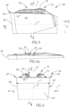
- the cutting insert 20 includes opposing insert front and rear surfaces 22, 24 and an insert peripheral surface 26 that extends between the insert front and rear surfaces 22, 24.
- the insert peripheral surface 26 extends about an insert central axis I.
- the insert central axis I can be a longitudinal axis so that the cutting insert 20 is elongated.
- the insert central axis I intersects the insert front and rear surfaces 22, 24.
- the insert peripheral surface 26 includes opposing insert top and bottom surfaces 28, 30 that connect the insert front and rear surfaces 22, 24.
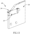
- the insert peripheral surface 26 further includes two opposing insert side surfaces, a first insert side surface 32A and a second insert side surface 32B that connect the insert front and rear surfaces 22, 24 and the insert top and bottom surfaces 28, 30 . It is also noticed that, in this non-limiting example, the cutting insert 20 is configured to be resiliently clamped in an insert pocket 34 ( Fig. 13 ) of an insert holder 36 and is thus formed without a clamping hole for receiving a clamping member (such as a retaining screw) therethrough.
- a clamping member such as a retaining screw
- the cutting insert 20 includes a cutting portion 38, for providing metal removing ability to the cutting insert 20 .
- the cutting insert 20 has just one cutting portion 38, located at one end of the cutting insert 20 .
- the cutting portion 38 has three mutually perpendicular axes, a cutting portion major axis A, a cutting portion vertical axis V and a cutting portion lateral axis F.
- the cutting portion major axis A defines a forward to rearward direction D F , D R .
- the cutting portion major axis A in a top view of the cutting portion 38 viewed along the cutting portion vertical axis V, can be parallel to, and aligned with, the insert central axis I .
- a side view of the cutting portion 38 viewed along the cutting portion lateral axis F i.e. Fig.
- the cutting portion major axis A and the insert central axis I can extend transversely to one another.
- the cutting portion vertical axis V defines an upward to downward direction D U , D D .
- the cutting portion lateral axis F defines at least a feed direction D.
- the cutting portion lateral axis F can also define a second feed direction D 2 , opposite the feed direction D.
- the cutting portion 38 has a symmetry plane S that contains the cutting portion major axis A and the cutting portion vertical axis V.
- the cutting portion 38 includes a forward cutting portion surface 40 formed on the insert front surface 22.
- the forward cutting portion surface 40 is intersected by the cutting portion major axis A and faces in the forward direction D F .
- the cutting portion 38 includes a rake surface 42 formed on the insert top surface 28.
- the rake surface 42 is intersected by the cutting portion vertical axis V and faces in the upward direction D U .
- the cutting portion 38 also includes a relief surface 44 formed on the first insert side surface 32A.
- the relief surface 44 is intersected by the cutting portion lateral axis F and faces in the feed direction D.
- the cutting portion 38 can include a second relief surface 48 formed on the second side surface 32B.
- the second relief surface 48 can be intersected by the cutting portion lateral axis F and faces in the second feed direction D 2 .
- the cutting portion vertical axis V extends between the relief surface 44 and the second relief surface 48.
- the symmetry plane S is positioned between the relief surface 44 and the second relief surface 48.
- a cutting portion corner 46 is formed at the intersection of the rake surface 42, the forward cutting portion surface 40 , the relief surface 44.
- a second cutting portion corner 50 can be formed at the intersection of the rake surface 42, the forward cutting portion surface 40 and the second relief surface 48.
- the cutting portion 38 includes a cutting edge 52 formed at the intersection of the rake surface 42 and the relief surface 44.
- the cutting edge 52 in a top view of the cutting portion 38, can be straight.
- the cutting edge 52 in a side view of the cutting portion 38, can be non-straight.
- the cutting edge 52 can have a wavy profile, formed by a plurality of cutting edge crests 54 and at least one cutting edge trough 56 that alternate with each other along the cutting edge 52.
- the cutting portion 38 can also include a second cutting edge 58 formed at the intersection of the rake surface 42 and the second relief surface 48.
- the second cutting edge 58 can be straight but not parallel with the cutting edge 52.
- the cutting portion 38 can include a forward cutting edge 60 formed at an intersection of the rake surface 42 and the forward cutting portion surface 40 .
- the forward cutting portion surface 40 can thus serve as a relief surface.
- the forward cutting edge 60 has a forward cutting edge length L, measured in the direction of the cutting portion lateral axis F.
- the forward cutting edge length L defines the width of the groove cut in the work piece, and also establishes the maximum width of the cutting portion 38.
- the forward cutting edge 60 can include two curved forward corner cutting edges 62 and a forward intermediate cutting edge 64 that extends between the two forward corner cutting edges 62.
- the forward corner cutting edges 62 can be formed at the cutting portion corner 46 and the second cutting portion corner 50 , respectively.
- the forward intermediate cutting edge 64 can be longer than each of the two forward corner cutting edges 62.
- the forward intermediate cutting edge 64 can be straight.
- the forward cutting edge 60 can be mirror symmetrical about an imaginary longitudinal plane which contains the cutting portion major axis A and passes through the insert top and bottom surfaces 28, 30 .
- the cutting portion major axis A may bisect the forward cutting edge 60 , in a top view of the cutting portion 38 (i.e. in a view in front of the rake surface 42 viewed along the cutting portion vertical axis V ).
- the cutting edge 52 and second cutting edge 58 can merge with the forward cutting edge 60 at opposite ends thereof.
- the rake surface 42 includes a land 66.
- the land 66 acts to strengthen the cutting edge 52.
- the land 66 is adjacent the cutting edge 52.
- the land 66 extends along the cutting edge 52. Referring to Fig. 5 , any point on the land 66 has a land inclination angle ⁇ defined by a tangent line T and a rake plane P, where the tangent line T is perpendicular to the cutting edge 52 in a top view of the cutting portion 38 and tangentially touches the land 66, and the rake plane P is oriented perpendicular to the cutting portion vertical axis V.
- the land 66 extends negatively away from the cutting edge 52. That is to say, the land 66 slopes upwardly from the cutting edge 52 so that the land inclination angle ⁇ is greater than 0°.
- the rake surface 42 can include a forward land 69.
- the forward land 69 can be adjacent the forward cutting edge 60 .
- the forward land 69 can extend along, and negatively away from, the forward cutting edge 60 .
- the forward land 69 has a forward land width W that can vary.
- the forward land width W at the forward intermediate cutting edge 64 can be greater than the forward land width W at the forward cutting corner cutting edges 62.
- the rake surface 42 can include a second land 70 .
- the second land 70 can be adjacent the second cutting edge 58.
- the second land 70 can extend along, and negatively away from, the second cutting edge 58.
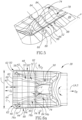
- the cutting portion 38 includes a chip-control arrangement 72 at the rake surface 42. It is understood that the cutting insert 20 in accordance with the subject matter of the present application could comprise one or more cutting portions 38 with such a chip-control arrangement 72 and one or more other cutting portions 38 which are devoid of any chip-control arrangement or which are formed with a different chip-control arrangement.
- the chip-control arrangement 72 is intended to control the flow and/or the shape and size of the swarf and debris resulting from metalworking operations.
- the chip-control arrangement 72 includes an elongated projection 74.
- the projection 74 serves to curve the chip in the feed direction D.
- the projection 74 projects from the rake surface 42.
- the projection 74 is spaced apart from the land 66.
- the projection 74 can be spaced apart from the land 66 by a chip forming groove 78 that undulates in the rearward direction D R away from the forward cutting portion surface 40 (see also Fig. 7 ).
- the projection 74 extends in a direction from a rearward portion of the cutting portion 38 towards a forward portion of the cutting portion 38.
- the projection 74 can include a forwardmost portion 76a and a rearmost portion 76b that merge with each other.
- the rearmost portion 76b of the projection 74 can form a majority of the length of the projection 74 (e.g. more than half the length of the projection 74 ).
- the forwardmost portion 76a of the projection 74 can extend in a direction towards the cutting portion corner 46.
- the rearmost portion 76b of the projection 74 can extend in a direction different than that of the forwardmost portion 76a of the projection 74.
- the rearmost portion 76b of the projection 74 can extend in a direction towards the forward cutting portion surface 40 .
- the projection 74 can increase in distance from the cutting edge 52 with increasing distance from the forward cutting portion surface 40 .
- the rearmost portion 76b of the projection 74 can extend longitudinally along a projection longitudinal axis C.
- the projection longitudinal axis C can form a projection angle ⁇ with the cutting portion major axis A.
- the projection angle ⁇ can be in the range, 5° ⁇ ⁇ ⁇ 15°.
- the projection longitudinal axis C can intersect the forward cutting edge 60 .
- the projection longitudinal axis C can intersect the forward intermediate cutting edge 64.
- the projection 74 can include two projection flank surfaces 74a and a central projection ridge surface 74b that extends therebetween in a widthwise direction of the projection 74.
- the projection ridge surface 74b can be higher than the two projection flank surfaces 74a in a widthwise cross-section.
- the central projection ridge surface 74b at the rearmost portion 76b of the projection 74 can extend along the projection longitudinal axis C (as seen in a top view of the cutting portion 38, i.e. Fig. 6a ).
- the projection ridge surface 74b can transition from being closer to the cutting edge 52 than to the cutting portion major axis A, to being closer to the cutting portion major axis A than to the cutting edge 52, as the projection ridge surface 74b extends in the rearward direction D R .
- the projection ridge 74b can include a plurality of projection crest portions 80 and at least one projection trough portions 82, each pair of adjacent projection crest portions 80 being spaced apart by a respective projection trough portion 82.
- Each projection crest portion 80 is higher than its adjacent projection trough portions 82.
- the plurality of projection crest portions 80 can be located above the cutting edge 52 as measured in an upward direction D U .
- the plurality of projection crest portions 80 can follow a pattern of increasing height in a rearward direction D R away from the forward cutting portion surface 40 .
- the at least one projection trough portion 82 can be located above the cutting edge 52 as measured in an upward direction Du.
- the chip-control arrangement 72 includes a plurality of elongated protuberances 84.
- the plurality of protuberances 84 serve to curve the chip in the direction of the cutting portion major axis A.
- the plurality of protuberances 84 project from the rake surface 42.
- the plurality of protuberances 84 are spaced apart from each other and the forward cutting portion surface 40 .
- each protuberance 84 can extend from a respective one of the projection crest portions 80 .
- the plurality of protuberances 84 may not be identical. Reference is made to Fig.
- each protuberance 84 can include two protuberance flank surfaces 84a and a central protuberance ridge surface 84b that extends therebetween in a widthwise direction of the protuberance 84.
- the protuberance ridge surface 84b can be higher than the two protuberance flank surfaces 84a in a widthwise cross-section.
- each protuberance 84 can include a protuberance lowest point LP.
- the protuberance lowest point LP can be spaced apart from the land 66.
- the protuberance lowest point LP can be vertically level with the cutting edge 52.
- each protuberance 84 can extend along a protuberance longitudinal axis PA.
- the protuberance longitudinal axes PA can be parallel with each other.
- the protuberance longitudinal axes PA may not be co-incident with a respective tangent line T.
- Each protuberance longitudinal axis PA can form a protuberance angle ⁇ with the cutting portion lateral axis F.
- the protuberance angle ⁇ can be in the range, 0° ⁇ ⁇ ⁇ 30°. In this non-limiting example shown in the drawings, the protuberance angle ⁇ is equal to 0° (i.e. the protuberance longitudinal axis PA and the cutting portion lateral axis F are parallel to each other).
- a central portion of the protuberance 84 in the protuberance axial plane P1 , can have a concave profile.
- the protuberance lowest point LP can be located at the concave profile.
- a central portion of the protuberance 84 in the protuberance radial plane P2, can have a convex profile.
- Each protuberance 84 extends from the projection 74.
- the projection flank surface 74a closest the cutting edge 52 can undulate in the rearward direction D R away from the forward cutting portion surface 40 .
- each protuberance 84 extends to the cutting edge 52. That is to say, each protuberance 84 terminates at the cutting edge 52.
- each protuberance 84 extends over (or via) the land 66.
- the land 66 includes a plurality of spaced apart upwardly bulging land portions 86. Each pair of adjacent bulging land portions 86 are spaced apart by a non-bulging land portion 88.
- the land 66 has a land height H, measured in the upward direction D U from the rake plane P that varies along the cutting edge 52.
- the land height H at each bulging land portion 86 defines a first land height H 1 that is greater than a second land height H 2 that is defined by the land height H at its adjacent non-bulging land portions 88.
- Each cutting edge crest 54 can be formed at a respective one of the bulging land portions 86.
- the land 66 (at both the bulging and non-bulging land portions 86, 88 ) can include a convexly curved land portion 68 that extends in the direction of the cutting edge 52.
- the convexly curved land portion 68 is also convexly curved in a direction away from the cutting edge 52.
- the land inclination angle ⁇ at the convexly curved land portion 68 can decrease in a direction away from the cutting edge 52.
- the convexly curved land portion 68 can be spaced apart from the cutting edge 52.
- the convexly curved land portion 68 can be defined by a convexly curved land radius R.
- the convexly curved land radius R can vary along the cutting edge 52 .
- the land inclination angle ⁇ at the cutting edge 52 at each of the bulging land portions 86 forms a bulging land inclination angle ⁇ 1 .
- the land inclination angle ⁇ at the cutting edge 52 at each of the non-bulging land portions 88 forms a non-bulging land inclination angle ⁇ 2 .
- the bulging land inclination angle ⁇ 1 at any given bulging land portion 86 can be greater than the non-bulging land inclination angles ⁇ 2 at its adjacent non-bulging land portions 88.
- the land inclination angle ⁇ at the cutting edge 52 can vary in alternating increasing and decreasing fashion, along the cutting edge 52.
- the bulging land inclination angle ⁇ 1 at any given bulging land portion 86 can be greater than the non-bulging land inclination angles ⁇ 2 at its adjacent non-bulging land portions 88 by no more than 5°.
- the bulging land inclination angle ⁇ 1 can be in the range, 20° ⁇ ⁇ 1 ⁇ 40°.
- the non-bulging land inclination angle ⁇ 2 can be in the range, 5° ⁇ ⁇ 2 ⁇ 30°.
- the land 66 transitions into the chip forming groove 78 where the surface upon which it extends changes from a negative orientation to a positive orientation. However, it is noted that at the bulging land portions 86 the land 66 may not transition to a positive orientation.
- the chip-control arrangement 72 can include an elongated second projection 90 .
- the second projection 90 can project from the rake surface 42.
- the second projection 90 can extend in a direction towards a forward portion of the cutting portion 38.
- the second projection 90 can be spaced apart from the second land 70 .
- the chip-control arrangement 72 can include a plurality of elongated second protuberances 92.
- the plurality of second protuberances 92 can project from the rake surface 42.
- the plurality of second protuberances 92 can be spaced apart from each other and the forward cutting portion surface 40 .
- Each second protuberance 92 can extend from the second projection 90 to the second cutting edge 58.
- Each second protuberance 92 can extend to the second cutting edge 58.
- Each second protuberance 92 can extend over (i.e. via) the second land 70 .
- the second land 70 can include a plurality of spaced apart second bulging land portions 94.
- the chip-control arrangement 72 can exhibit mirror symmetry about the symmetry plane S
- the cutting portion 38 can exhibit mirror symmetry about the symmetry plane S.
- any or all of the features relating to the relief surface 44, cutting portion corner 46, cutting edge 52, land 66, projection 74, protuberance 84 and bulging land portion 86 can apply to the second relief surface 48, second cutting portion corner 50 , second cutting edge 58, second land 70 , second projection 90 , second protuberance 92 and second bulging land portion 94, respectively.
- a second aspect of the present application relates to a non-rotary cutting tool 96.
- the cutting tool 96 can be designed for turning cutting operations as opposed to milling or drilling cutting operation.
- the cutting tool 96 includes a cutting insert 20 and an insert holder 36.
- the insert holder 36 includes an insert pocket 34, with the cutting insert 20 releasable retained in the insert pocket 34.
- chip-control arrangement 72 has been found to be effective for turning and in particular groove-turning cutting methods.
- chip-control arrangement 72 has been found to be effective for cutting different metal work-piece materials such as steel, stainless steel and high temperature metal alloys, such as nickel.
- chip-control arrangement 72 has been found to be effective for multiple applications, such as full width grooving, partial (finish) grooving, finish turning, and turning.
Landscapes
- Engineering & Computer Science (AREA)
- Mechanical Engineering (AREA)
- Cutting Tools, Boring Holders, And Turrets (AREA)
- Milling Processes (AREA)
- Road Repair (AREA)
- Joining Of Corner Units Of Frames Or Wings (AREA)
- Knives (AREA)
Claims (15)
- Schneideinsatz (20), aufweisend:
einen Schneidabschnitt (38) mit einer Schneidabschnitts-Hauptachse (A), die entgegengesetzte Richtungen nach vorn und nach hinten (DF, DR) definiert, und einer Schneidabschnitts-Querachse (F), die in einer Draufsicht auf den Schneidabschnitt (38) senkrecht zur Schneidabschnitts-Hauptachse (A) ausgerichtet ist und eine Vorschubrichtung (D) definiert, wobei der Schneidabschnitt (38) aufweist:eine Schneidabschnittsecke (46), die am Schnittbereich einer nach oben weisenden Spanfläche (42), einer nach vorn weisenden vorderen Schneidabschnittsfläche (40) und einer in Vorschubrichtung (D) weisenden Freifläche (44) ausgebildet ist;eine Schneidkante (52), die an einem Schnittbereich der Spanfläche (42) und der Freifläche (44) ausgebildet ist;einen Steg (66), der sich auf der Spanfläche (42) befindet;
undeine Spanbrecheranordnung (72) and der Spanfläche (42), aufweisend:einen länglichen Vorsprung (74), der von der Spanfläche (42) vorsteht, von dem Steg (66) beabstandet ist und sich in einer Richtung von einem hinteren Abschnitt zu einem vorderen Abschnitt des Schneidabschnitts (38) erstreckt;dadurch gekennzeichnet, dass:sich der Steg (66) entlang der Schneidkante (52) und negativ von dieser weg erstreckt; unddie Spanbrecheranordnung (72) an der Spanfläche (42) aufweist:
mehrere längliche Wölbungen (84), die von der Spanfläche (42) vorstehen und voneinander und von der vorderen Schneidabschnittsfläche (40) beabstandet sind, wobei sich jede Wölbung (84) von dem Vorsprung (74) bis zur Schneidkante (52) erstreckt, sodass der Steg (66) mehrere voneinander beabstandete, nach oben gewölbte Stegabschnitte (86) aufweist. - Schneideinsatz (20) nach Anspruch 1, wobei:jedes Paar von benachbarten gewölbten Stegabschnitten (86) durch einen wölbungslosen Stegabschnitt (88) voneinander beabstandet ist;der Stegneigungswinkel (θ) an der Schneidkante (52) an jedem der gewölbten Stegabschnitte (86) einen Wölbungssteg-Neigungswinkel (θ1) bildet;der Stegneigungswinkel (θ) an der Schneidkante (52) an jedem der wölbungslosen Stegabschnitte (88) einen Nichtwölbungssteg-Neigungswinkel (θ2) bildet;der Wölbungssteg-Neigungswinkel (θ1) an einem beliebigen gewölbten Stegabschnitt (86) größer als die Nichtwölbungssteg-Neigungswinkel (θ2) an den benachbarten wölbungslosen Stegabschnitten (88) ist, und zwar bevorzugt um 5°, und dass weiter bevorzugtder Wölbungssteg-Neigungswinkel (θ1) im Bereich von 20° ≤ Wölbungssteg-Neigungswinkel (θ1) ≤ 40° liegt; undder Nichtwölbungssteg-Neigungswinkel (θ2) im Bereich von 5° ≤ Nichtwölbungssteg-Neigungswinkel (θ2) ≤ 30° liegt,der Nichtwölbungssteg-Neigungswinkel (θ2) im Bereich von 5° ≤ (θ2) ≤ 30° liegt.
- Schneideinsatz (20) nach Anspruch 2, wobei die die Wölbungssteg-Neigungswinkel (θ1) in einer Richtung von der vorderen Schneidabschnittsfläche (40) weg einem Muster mit zunehmendem Wert folgen.
- Schneideinsatz (20) nach einem der Ansprüche 1-3, wobei in einer Querschnittsansicht in einer Quervorschubebene (FP), die senkrecht zur Schneidabschnitts-Querachse (F) angeordnet ist und die mehreren Wölbungen (84) schneidet, die mehreren Wölbungen (84) einem Muster mit zunehmender Höhe in einer Richtung (DR) nach hinten von der vorderen Schneidabschnittsfläche (40) weg folgen.
- Schneideinsatz (20) nach einem der Ansprüche 1-4, wobei der Vorsprung (74) von dem Steg (66) durch eine Spanbildungsnut (78) beabstandet ist, die in der Richtung (DR) nach hinten von der vorderen Schneidabschnittsfläche (40) weg gewellt ist.
- Schneideinsatz (20) nach einem der Ansprüche 1-5, wobei der Abstand des Vorsprungs (74) zur Schneidkante (52) mit zunehmendem Abstand von der vorderen Schneidabschnittsfläche (40) zunimmt.
- Schneideinsatz (20) nach einem der Ansprüche 1-6, wobei sich ein vorderster Abschnitt (76a) des Vorsprungs (74) in einer Richtung zur Schneidabschnittsecke (46) erstreckt.
- Schneideinsatz (20) nach einem der Ansprüche 1-7, wobei:
sich ein hinterster Abschnitt (76b) des Vorsprungs (74) in Längsrichtung entlang einer Vorsprungslängsachse (C) erstreckt;die Vorsprungslängsachse (C) in einer Draufsicht auf den Schneidabschnitt (38) einen Projektionswinkel (α) mit der Schneidabschnitts-Hauptachse (A) bildet; undder Projektionswinkel (α) im Bereich von 5° ≤ (α) ≤ 15° liegt. - Schneideinsatz (20) nach einem der Ansprüche 1-8, wobei:der Vorsprung (74) zwei Vorsprungsflankenflächen (74a) und eine mittig angeordnete Vorsprungskammfläche (74b) aufweist, die sich dazwischen in einer Breitenrichtung des Vorsprungs (74) erstreckt, wobei die Vorsprungskammfläche (74b) in einem Breitenquerschnitt höher als die beiden Vorsprungsflankenflächen (74a) ist und bevorzugt die Vorsprungskammfläche (74b) in einer Draufsicht auf den Schneidabschnitt (38) zwischen der Schneidabschnitt-Hauptachse (A) und der Schneidkante (52) angeordnet ist, und,weiter bevorzugt die Vorsprungskammfläche (74b) von näher an der Schneidkante (52) als an der Schneidabschnitts-Hauptachse (A) zu näher an der Schneidabschnitts-Hauptachse (A) als an der Schneidkante (52) übergeht, wenn sich die Vorsprungskammfläche (74b) in Richtung (DR) nach hinten erstreckt.
- Schneideinsatz (20) nach einem der Ansprüche 1-9, wobei:die Vorsprungskammfläche (74b) mehrere Vorsprungsscheitelabschnitte (80) und mindestens einen Vorsprungsmuldenabschnitt (82) aufweist, wobei jedes benachbarte Paar von Vorsprungsscheitelabschnitten (80) durch einen entsprechenden Vorsprungsmuldenabschnitt (82) voneinander beabstandet ist und jeder Vorsprungsscheitelabschnitt (80) höher als seine benachbarten Vorsprungsmuldenabschnitte (82) ist; undsich jede Wölbung (84) von einem entsprechenden der Vorsprungsscheitelabschnitte (80) aus erstreckt, undbevorzugt die mehreren Vorsprungsscheitelabschnitte (80) nach hinten in Richtung (DR) weg von der vorderen Schneidabschnittsfläche (40) einem Muster mit zunehmender Höhe folgen, undweiter bevorzugt sich die mehreren Vorsprungsscheitelabschnitte (80) in Aufwärtsrichtung (DU) gemessen oberhalb der Schneidkante (52) befinden.
- Schneideinsatz (20) nach einem der Ansprüche 1-10, wobei: sich jede Wölbung (84) entlang einer Wölbungslängsachse (PA) erstreckt;jede Wölbungslängsachse (PA) in einer Draufsicht auf den Schneidabschnitt (38) einen Wölbungswinkel (β) mit der Schneidabschnitts-Querachse (F) bildet; undder Wölbungswinkel (β) im Bereich von 0° ≤ der Wölbungswinkel (β) ≤ 30° liegt, undbevorzugt die Wölbungslängsachsen (PA) in einer Draufsicht auf den Schneidabschnitt (38) parallel zueinander verlaufen, undweiter bevorzugt in einer Querschnittsansicht in einer axialen Wölbungsebene (P1), die eine der Wölbungslängsachsen (PA) enthält und die Span- und Freifläche (42, 44) schneidet, ein Mittelteil der Wölbung (84) ein konkaves Profil aufweist, undnoch weiter bevorzugt ein Mittelteil der Wölbung (84) in einer Querschnittsansicht in einer radialen Wölbungsebene (P2), die senkrecht zu einer der Wölbungslängsachsen (PA) verläuft und die Wölbung (84) schneidet, ein konvexes Profil aufweist.
- Schneideinsatz (20) nach einem der Ansprüche 1-11, wobei die Schneidkante (52) in einer Seitenansicht des Schneidabschnitts (38) ein wellenförmiges Profil aufweist, das durch mehrere Schneidkantenscheitel (54) und mindestens eine Schneidkantenmulde (56) gebildet wird, wobei jeder Schneidkantenscheitel (54) an einem entsprechenden der gewölbten Stegabschnitte (86) ausgebildet ist.
- Schneideinsatz (20) nach einem der Ansprüche 1-12, wobei der Steg (66) einen konvex gekrümmten Stegabschnitt (68) aufweist, der sich in der Richtung zur Schneidkante (52) erstreckt und in einer Richtung von der Schneidkante (52) weg konvex gekrümmt ist.
- Schneideinsatz (20) nach einem der Ansprüche 1-13, wobei die Schneidabschnitt-Querachse (F) eine zweite Vorschubrichtung (D2) definiert, die der Vorschubrichtung (D) entgegengesetzt ist, wobei der Schneidabschnitt (38) ferner aufweist:eine zweite Schneidabschnittsecke (50), die an dem Schnittbereich der Spanfläche (42), der vorderen Schneidabschnittsfläche (40) und einer zweiten Freifläche (48), die in die zweite Vorschubrichtung (D2) weist, ausgebildet ist;eine zweite Schneidkante (58), die an einem Schnittbereich der Spanfläche (42) und der zweiten Freifläche (48) ausgebildet ist;einen zweiten Steg (70), der sich auf der Spanfläche (42) befindet und sich entlang der zweiten Schneidkante (58) und negativ von dieser weg erstreckt; wobei die Spanbrecheranordnung (72) ferner aufweist:einen länglichen zweiten Vorsprung, (90) der von der Spanfläche (42) vorsteht, von dem zweiten Steg (70) beabstandet ist und sich in Richtung eines vorderen Abschnitts des Schneidabschnitts (38) erstreckt; undmehrere längliche zweite Wölbungen (92), die von der Spanfläche (42) vorstehen und voneinander und von der vorderen Schneidabschnittsfläche (40) beabstandet sind, wobei sich jede zweite Wölbung (92) von dem zweiten Vorsprung (90) zur zweiten Schneidkante (58) erstreckt, sodass der zweite Steg (70) mehrere voneinander beabstandete zweite gewölbte Stegabschnitte (94) aufweist, undbevorzugt der Schneidabschnitt (38) ferner eine vordere Schneidkante (60) aufweist, die an einem Schnittbereich der Spanfläche (42) und der vorderen Schneidabschnittsfläche (40) ausgebildet ist; unddie vordere Schneidkante (60) in einer Draufsicht auf den Schneidabschnitt (38) eine vordere Schneidkantenlänge (L) aufweist, die auch eine maximale Breitenabmessung des Schneideinsatzes (20) in einer Richtung senkrecht zur Schneidabschnitt-Hauptachse (A) definiert, undweiter bevorzugt die Spanbrecheranordnung (72) Spiegelsymmetrie um eine Symmetrieebene (S) aufweist, die die Schneidabschnitts-Hauptachse (A) und eine vertikale Achse (V) des Schneidabschnitts enthält, die senkrecht zur Schneidabschnitts-Hauptachse (A) verläuft und sich zwischen der Freifläche (44) und der zweiten Freifläche (48) erstreckt.
- Nicht rotierendes Schneidwerkzeug (96), aufweisend:einen Schneideinsatz (20) nach einem der Ansprüche 1-14; undeinen Einsatzhalter (36), der eine Einsatztasche (34) aufweist; wobei:
der Schneideinsatz (20) lösbar in der Einsatztasche (34) gehalten ist.
Applications Claiming Priority (2)
| Application Number | Priority Date | Filing Date | Title |
|---|---|---|---|
| US201862636225P | 2018-02-28 | 2018-02-28 | |
| PCT/IL2019/050036 WO2019167037A1 (en) | 2018-02-28 | 2019-01-08 | Cutting insert having land with spaced apart upwardly bulging land portions and non-rotary cutting tool provided therewith |
Publications (2)
| Publication Number | Publication Date |
|---|---|
| EP3758874A1 EP3758874A1 (de) | 2021-01-06 |
| EP3758874B1 true EP3758874B1 (de) | 2024-10-23 |
Family
ID=65228609
Family Applications (1)
| Application Number | Title | Priority Date | Filing Date |
|---|---|---|---|
| EP19701739.5A Active EP3758874B1 (de) | 2018-02-28 | 2019-01-08 | Schneideinsatz mit einem steg mit voneinander beabstandeten, nach oben gewölbten stegabschnitten und nichtrotierendes schneidwerkzeug damit |
Country Status (13)
| Country | Link |
|---|---|
| US (1) | US10987740B2 (de) |
| EP (1) | EP3758874B1 (de) |
| JP (1) | JP7275149B2 (de) |
| KR (1) | KR102587432B1 (de) |
| CN (1) | CN111770805B (de) |
| CA (1) | CA3098545A1 (de) |
| ES (1) | ES2993353T3 (de) |
| IL (1) | IL276550B2 (de) |
| PL (1) | PL3758874T3 (de) |
| PT (1) | PT3758874T (de) |
| RU (1) | RU2768817C1 (de) |
| TW (1) | TWI773866B (de) |
| WO (1) | WO2019167037A1 (de) |
Families Citing this family (4)
| Publication number | Priority date | Publication date | Assignee | Title |
|---|---|---|---|---|
| TWI773866B (zh) | 2018-02-28 | 2022-08-11 | 以色列商艾斯卡公司 | 具有含間隔開的向上凸起刃帶部之刃帶的切削嵌件、及設有該切削嵌件的非旋轉式切削刀具 |
| JP6923854B1 (ja) * | 2021-02-26 | 2021-08-25 | 株式会社タンガロイ | 切削インサート |
| USD953396S1 (en) * | 2021-04-29 | 2022-05-31 | Korloy Inc. | Grooving insert for machine tools for metalworking |
| JP7741484B2 (ja) * | 2024-02-27 | 2025-09-18 | 株式会社タンガロイ | 切削工具 |
Citations (10)
| Publication number | Priority date | Publication date | Assignee | Title |
|---|---|---|---|---|
| US4969779A (en) | 1989-02-10 | 1990-11-13 | Iscar Ltd. | Cutting insert |
| DE4141368A1 (de) | 1991-12-14 | 1993-06-17 | Krupp Widia Gmbh | Schneideinsatz |
| WO1996011763A1 (de) | 1994-10-17 | 1996-04-25 | Widia Gmbh | Vieleckiger schneideinsatz |
| US5725334A (en) | 1993-03-29 | 1998-03-10 | Widia Gmbh | Cutting insert |
| JP2005288613A (ja) | 2004-03-31 | 2005-10-20 | Mitsubishi Materials Corp | スローアウェイチップ |
| EP1702702A1 (de) | 2005-03-16 | 2006-09-20 | Sandvik Intellectual Property AB | Planfräseinsatz |
| EP2412464A1 (de) | 2009-03-24 | 2012-02-01 | Hitachi Tool Engineering, Ltd. | Drehwerkzeug mit schneidspitzenauswechselung |
| CN103009333A (zh) | 2012-12-24 | 2013-04-03 | 株洲欧科亿硬质合金有限公司 | 一种用于粗加工的可转位切削刀片 |
| WO2014017623A1 (ja) | 2012-07-26 | 2014-01-30 | 京セラ株式会社 | 切削インサートおよび切削工具、ならびにそれらを用いた切削加工物の製造方法 |
| CN205650832U (zh) | 2016-04-11 | 2016-10-19 | 大连远东钨业科技股份有限公司 | 一种粗加工可转位数控车削刀片 |
Family Cites Families (33)
| Publication number | Priority date | Publication date | Assignee | Title |
|---|---|---|---|---|
| US3654681A (en) * | 1970-04-22 | 1972-04-11 | Warner Swasey Co | Cutoff tool having improved chip relieving surface |
| US4629372A (en) * | 1981-02-02 | 1986-12-16 | Manchester Tool Company | Chip-controlling insert |
| CA1194283A (en) * | 1981-02-02 | 1985-10-01 | Mark F. Huston | Regrindable chip controlling insert |
| SE454248B (sv) * | 1986-08-18 | 1988-04-18 | Sandvik Ab | Sker for spar- och avstickning |
| SU1465176A2 (ru) * | 1986-12-01 | 1989-03-15 | Предприятие П/Я Р-6564 | Режуща пластина |
| SU1720802A1 (ru) * | 1990-03-11 | 1992-03-23 | Научно-Исследовательская Лаборатория "Карбидные Материалы" | Резец |
| SU1710201A1 (ru) * | 1990-05-04 | 1992-02-07 | Новосибирский Филиал Специального Производственно-Технологического Бюро "Оргпримтвердосплав" | Режуща пластина |
| GB2290994B (en) * | 1994-07-05 | 1998-06-10 | Valenite Inc | Cutting insert |
| DE59504505D1 (de) | 1994-09-12 | 1999-01-21 | Widia Gmbh | Stecheinsatz zur spanabhebenden bearbeitung von werkstücken |
| DE19528851A1 (de) * | 1995-08-05 | 1997-02-06 | Widia Gmbh | Polygonaler Schneideinsatz |
| SE505165C2 (sv) * | 1996-06-06 | 1997-07-07 | Sandvik Ab | Skär för spårstickning |
| SE514872C2 (sv) * | 1998-09-09 | 2001-05-07 | Sandvik Ab | Skär för spårsvarvning |
| JP4465809B2 (ja) * | 1999-07-09 | 2010-05-26 | 三菱マテリアル株式会社 | スローアウェイチップ |
| SE525729C2 (sv) * | 2002-01-31 | 2005-04-12 | Sandvik Ab | Skär för spårstickning och profilering |
| CN1774318B (zh) * | 2002-10-18 | 2010-12-08 | 肯纳合金公司 | 刀夹和带有断屑面的金属切削刀片 |
| IL159188A (en) * | 2003-12-04 | 2008-08-07 | Uzi Gati | Cutting placement for diligent operations |
| US6979153B1 (en) * | 2004-08-20 | 2005-12-27 | Sandvik Ab | Deep-grooving insert having stepped cutting edge |
| US7665933B2 (en) | 2007-03-30 | 2010-02-23 | Mitsubishi Materials Corporation | Cutting insert |
| KR100901470B1 (ko) * | 2007-07-05 | 2009-06-08 | 대구텍 주식회사 | 코너 리세스부를 지니는 절삭 인서트 |
| CN102712046B (zh) * | 2010-01-29 | 2014-05-21 | 京瓷株式会社 | 切削镶刀及切削工具、以及使用该切削工具的被切削件的切削方法 |
| JP5639656B2 (ja) | 2010-09-29 | 2014-12-10 | 京セラ株式会社 | 切削インサートおよび切削工具、並びにそれらを用いた切削加工物の製造方法 |
| CN103379975B (zh) | 2011-02-28 | 2016-02-24 | 京瓷株式会社 | 切削刀具及切削工具,以及使用它们的切削加工物的制造方法 |
| US8939684B2 (en) | 2012-05-15 | 2015-01-27 | Iscar, Ltd. | Cutting insert with chip-control arrangement having recess depths and projection heights which increase with distance from cutting edge |
| DE102012111576B4 (de) | 2012-11-29 | 2022-05-25 | Kennametal Inc. | Schneideinsatz mit Kühlmittelkanal und Schneidwerkzeug mit einem Werkzeughalter und einem solchen Schneideinsatz |
| JP6206801B2 (ja) * | 2013-09-09 | 2017-10-04 | 住友電工ハードメタル株式会社 | 切削インサート |
| US9421615B2 (en) * | 2014-04-10 | 2016-08-23 | Iscar, Ltd. | Cutting tool and cutting insert having exactly four cutting portions therefor |
| US10076788B2 (en) * | 2014-05-20 | 2018-09-18 | Iscar, Ltd. | Cutting insert with chip-control arrangement |
| US9579727B2 (en) | 2014-05-28 | 2017-02-28 | Kennametal Inc. | Cutting assembly with cutting insert having enhanced coolant delivery |
| EP3153260B1 (de) | 2015-10-09 | 2018-05-23 | Sandvik Intellectual Property AB | Dreheinsatz und verfahren |
| EP3153261B1 (de) | 2015-10-09 | 2018-04-04 | Sandvik Intellectual Property AB | Dreheinsatz und verfahren |
| JP2017177285A (ja) | 2016-03-30 | 2017-10-05 | 日本特殊陶業株式会社 | 切削インサート |
| CN107626936A (zh) * | 2017-09-23 | 2018-01-26 | 哈尔滨理工大学 | 一种高温合金用新型减磨车刀片 |
| TWI773866B (zh) | 2018-02-28 | 2022-08-11 | 以色列商艾斯卡公司 | 具有含間隔開的向上凸起刃帶部之刃帶的切削嵌件、及設有該切削嵌件的非旋轉式切削刀具 |
-
2019
- 2019-01-02 TW TW108100021A patent/TWI773866B/zh active
- 2019-01-03 US US16/238,958 patent/US10987740B2/en active Active
- 2019-01-08 ES ES19701739T patent/ES2993353T3/es active Active
- 2019-01-08 PL PL19701739.5T patent/PL3758874T3/pl unknown
- 2019-01-08 WO PCT/IL2019/050036 patent/WO2019167037A1/en not_active Ceased
- 2019-01-08 PT PT197017395T patent/PT3758874T/pt unknown
- 2019-01-08 EP EP19701739.5A patent/EP3758874B1/de active Active
- 2019-01-08 RU RU2020126298A patent/RU2768817C1/ru active
- 2019-01-08 IL IL276550A patent/IL276550B2/en unknown
- 2019-01-08 CN CN201980015556.9A patent/CN111770805B/zh active Active
- 2019-01-08 KR KR1020207024892A patent/KR102587432B1/ko active Active
- 2019-01-08 CA CA3098545A patent/CA3098545A1/en active Pending
- 2019-01-08 JP JP2020537702A patent/JP7275149B2/ja active Active
Patent Citations (10)
| Publication number | Priority date | Publication date | Assignee | Title |
|---|---|---|---|---|
| US4969779A (en) | 1989-02-10 | 1990-11-13 | Iscar Ltd. | Cutting insert |
| DE4141368A1 (de) | 1991-12-14 | 1993-06-17 | Krupp Widia Gmbh | Schneideinsatz |
| US5725334A (en) | 1993-03-29 | 1998-03-10 | Widia Gmbh | Cutting insert |
| WO1996011763A1 (de) | 1994-10-17 | 1996-04-25 | Widia Gmbh | Vieleckiger schneideinsatz |
| JP2005288613A (ja) | 2004-03-31 | 2005-10-20 | Mitsubishi Materials Corp | スローアウェイチップ |
| EP1702702A1 (de) | 2005-03-16 | 2006-09-20 | Sandvik Intellectual Property AB | Planfräseinsatz |
| EP2412464A1 (de) | 2009-03-24 | 2012-02-01 | Hitachi Tool Engineering, Ltd. | Drehwerkzeug mit schneidspitzenauswechselung |
| WO2014017623A1 (ja) | 2012-07-26 | 2014-01-30 | 京セラ株式会社 | 切削インサートおよび切削工具、ならびにそれらを用いた切削加工物の製造方法 |
| CN103009333A (zh) | 2012-12-24 | 2013-04-03 | 株洲欧科亿硬质合金有限公司 | 一种用于粗加工的可转位切削刀片 |
| CN205650832U (zh) | 2016-04-11 | 2016-10-19 | 大连远东钨业科技股份有限公司 | 一种粗加工可转位数控车削刀片 |
Also Published As
| Publication number | Publication date |
|---|---|
| JP2021514859A (ja) | 2021-06-17 |
| RU2768817C1 (ru) | 2022-03-24 |
| CA3098545A1 (en) | 2019-09-06 |
| PT3758874T (pt) | 2024-11-18 |
| BR112020017454A2 (pt) | 2020-12-22 |
| CN111770805B (zh) | 2023-07-28 |
| JP7275149B2 (ja) | 2023-05-17 |
| US10987740B2 (en) | 2021-04-27 |
| PL3758874T3 (pl) | 2025-01-13 |
| US20190262908A1 (en) | 2019-08-29 |
| IL276550B2 (en) | 2024-02-01 |
| TWI773866B (zh) | 2022-08-11 |
| KR20200124682A (ko) | 2020-11-03 |
| EP3758874A1 (de) | 2021-01-06 |
| TW201936299A (zh) | 2019-09-16 |
| ES2993353T3 (en) | 2024-12-27 |
| IL276550B1 (en) | 2023-10-01 |
| CN111770805A (zh) | 2020-10-13 |
| KR102587432B1 (ko) | 2023-10-11 |
| WO2019167037A1 (en) | 2019-09-06 |
| IL276550A (en) | 2020-09-30 |
Similar Documents
| Publication | Publication Date | Title |
|---|---|---|
| EP3758874B1 (de) | Schneideinsatz mit einem steg mit voneinander beabstandeten, nach oben gewölbten stegabschnitten und nichtrotierendes schneidwerkzeug damit | |
| CA2541901C (en) | Cutting insert for high feed face milling | |
| EP2214857B1 (de) | Tangentialschneideeinsatz | |
| AU766054B2 (en) | Cutting insert | |
| US10384268B1 (en) | Grooving insert having rearwardly pointing arrowhead-shaped chip former | |
| IL106536A (en) | Insert for a milling cutter | |
| JP6361948B2 (ja) | 切削インサートおよび切削工具 | |
| EP3624970B1 (de) | Schneideinsatz mit einer spaltschneidkante mit vorder- und hinterkantenkomponentenschneidkante | |
| CN110000400B (zh) | 一种双面槽型切削刀片 | |
| EP1425126B1 (de) | Schneideinsatz | |
| BR112020017454B1 (pt) | Inserto de corte, e, ferramenta de corte não rotativa | |
| JPH11197909A (ja) | スローアウェイチップ |
Legal Events
| Date | Code | Title | Description |
|---|---|---|---|
| STAA | Information on the status of an ep patent application or granted ep patent |
Free format text: STATUS: UNKNOWN |
|
| STAA | Information on the status of an ep patent application or granted ep patent |
Free format text: STATUS: THE INTERNATIONAL PUBLICATION HAS BEEN MADE |
|
| PUAI | Public reference made under article 153(3) epc to a published international application that has entered the european phase |
Free format text: ORIGINAL CODE: 0009012 |
|
| STAA | Information on the status of an ep patent application or granted ep patent |
Free format text: STATUS: REQUEST FOR EXAMINATION WAS MADE |
|
| 17P | Request for examination filed |
Effective date: 20200907 |
|
| AK | Designated contracting states |
Kind code of ref document: A1 Designated state(s): AL AT BE BG CH CY CZ DE DK EE ES FI FR GB GR HR HU IE IS IT LI LT LU LV MC MK MT NL NO PL PT RO RS SE SI SK SM TR |
|
| AX | Request for extension of the european patent |
Extension state: BA ME |
|
| DAV | Request for validation of the european patent (deleted) | ||
| DAX | Request for extension of the european patent (deleted) | ||
| GRAP | Despatch of communication of intention to grant a patent |
Free format text: ORIGINAL CODE: EPIDOSNIGR1 |
|
| STAA | Information on the status of an ep patent application or granted ep patent |
Free format text: STATUS: GRANT OF PATENT IS INTENDED |
|
| INTG | Intention to grant announced |
Effective date: 20240606 |
|
| GRAS | Grant fee paid |
Free format text: ORIGINAL CODE: EPIDOSNIGR3 |
|
| GRAA | (expected) grant |
Free format text: ORIGINAL CODE: 0009210 |
|
| STAA | Information on the status of an ep patent application or granted ep patent |
Free format text: STATUS: THE PATENT HAS BEEN GRANTED |
|
| AK | Designated contracting states |
Kind code of ref document: B1 Designated state(s): AL AT BE BG CH CY CZ DE DK EE ES FI FR GB GR HR HU IE IS IT LI LT LU LV MC MK MT NL NO PL PT RO RS SE SI SK SM TR |
|
| P01 | Opt-out of the competence of the unified patent court (upc) registered |
Free format text: CASE NUMBER: APP_51827/2024 Effective date: 20240916 |
|
| REG | Reference to a national code |
Ref country code: GB Ref legal event code: FG4D |
|
| REG | Reference to a national code |
Ref country code: CH Ref legal event code: EP |
|
| REG | Reference to a national code |
Ref country code: DE Ref legal event code: R096 Ref document number: 602019060743 Country of ref document: DE |
|
| REG | Reference to a national code |
Ref country code: PT Ref legal event code: SC4A Ref document number: 3758874 Country of ref document: PT Date of ref document: 20241118 Kind code of ref document: T Free format text: AVAILABILITY OF NATIONAL TRANSLATION Effective date: 20241112 |
|
| REG | Reference to a national code |
Ref country code: IE Ref legal event code: FG4D |
|
| REG | Reference to a national code |
Ref country code: SE Ref legal event code: TRGR |
|
| REG | Reference to a national code |
Ref country code: ES Ref legal event code: FG2A Ref document number: 2993353 Country of ref document: ES Kind code of ref document: T3 Effective date: 20241227 |
|
| PGFP | Annual fee paid to national office [announced via postgrant information from national office to epo] |
Ref country code: GB Payment date: 20241213 Year of fee payment: 7 |
|
| PGFP | Annual fee paid to national office [announced via postgrant information from national office to epo] |
Ref country code: FR Payment date: 20241205 Year of fee payment: 7 |
|
| PGFP | Annual fee paid to national office [announced via postgrant information from national office to epo] |
Ref country code: CZ Payment date: 20241203 Year of fee payment: 7 |
|
| PGFP | Annual fee paid to national office [announced via postgrant information from national office to epo] |
Ref country code: SE Payment date: 20241211 Year of fee payment: 7 |
|
| REG | Reference to a national code |
Ref country code: LT Ref legal event code: MG9D |
|
| REG | Reference to a national code |
Ref country code: NL Ref legal event code: MP Effective date: 20241023 |
|
| PG25 | Lapsed in a contracting state [announced via postgrant information from national office to epo] |
Ref country code: NL Free format text: LAPSE BECAUSE OF FAILURE TO SUBMIT A TRANSLATION OF THE DESCRIPTION OR TO PAY THE FEE WITHIN THE PRESCRIBED TIME-LIMIT Effective date: 20241023 |
|
| PG25 | Lapsed in a contracting state [announced via postgrant information from national office to epo] |
Ref country code: NL Free format text: LAPSE BECAUSE OF FAILURE TO SUBMIT A TRANSLATION OF THE DESCRIPTION OR TO PAY THE FEE WITHIN THE PRESCRIBED TIME-LIMIT Effective date: 20241023 |
|
| PG25 | Lapsed in a contracting state [announced via postgrant information from national office to epo] |
Ref country code: IS Free format text: LAPSE BECAUSE OF FAILURE TO SUBMIT A TRANSLATION OF THE DESCRIPTION OR TO PAY THE FEE WITHIN THE PRESCRIBED TIME-LIMIT Effective date: 20250223 Ref country code: HR Free format text: LAPSE BECAUSE OF FAILURE TO SUBMIT A TRANSLATION OF THE DESCRIPTION OR TO PAY THE FEE WITHIN THE PRESCRIBED TIME-LIMIT Effective date: 20241023 |
|
| PGFP | Annual fee paid to national office [announced via postgrant information from national office to epo] |
Ref country code: DE Payment date: 20241205 Year of fee payment: 7 |
|
| PG25 | Lapsed in a contracting state [announced via postgrant information from national office to epo] |
Ref country code: FI Free format text: LAPSE BECAUSE OF FAILURE TO SUBMIT A TRANSLATION OF THE DESCRIPTION OR TO PAY THE FEE WITHIN THE PRESCRIBED TIME-LIMIT Effective date: 20241023 |
|
| PG25 | Lapsed in a contracting state [announced via postgrant information from national office to epo] |
Ref country code: BG Free format text: LAPSE BECAUSE OF FAILURE TO SUBMIT A TRANSLATION OF THE DESCRIPTION OR TO PAY THE FEE WITHIN THE PRESCRIBED TIME-LIMIT Effective date: 20241023 |
|
| PGFP | Annual fee paid to national office [announced via postgrant information from national office to epo] |
Ref country code: ES Payment date: 20250203 Year of fee payment: 7 |
|
| PG25 | Lapsed in a contracting state [announced via postgrant information from national office to epo] |
Ref country code: NO Free format text: LAPSE BECAUSE OF FAILURE TO SUBMIT A TRANSLATION OF THE DESCRIPTION OR TO PAY THE FEE WITHIN THE PRESCRIBED TIME-LIMIT Effective date: 20250123 |
|
| PG25 | Lapsed in a contracting state [announced via postgrant information from national office to epo] |
Ref country code: GR Free format text: LAPSE BECAUSE OF FAILURE TO SUBMIT A TRANSLATION OF THE DESCRIPTION OR TO PAY THE FEE WITHIN THE PRESCRIBED TIME-LIMIT Effective date: 20250124 Ref country code: LV Free format text: LAPSE BECAUSE OF FAILURE TO SUBMIT A TRANSLATION OF THE DESCRIPTION OR TO PAY THE FEE WITHIN THE PRESCRIBED TIME-LIMIT Effective date: 20241023 |
|
| PGFP | Annual fee paid to national office [announced via postgrant information from national office to epo] |
Ref country code: AT Payment date: 20241205 Year of fee payment: 7 Ref country code: CH Payment date: 20250201 Year of fee payment: 7 |
|
| PGFP | Annual fee paid to national office [announced via postgrant information from national office to epo] |
Ref country code: PL Payment date: 20241205 Year of fee payment: 7 |
|
| PGFP | Annual fee paid to national office [announced via postgrant information from national office to epo] |
Ref country code: IT Payment date: 20241205 Year of fee payment: 7 |
|
| PG25 | Lapsed in a contracting state [announced via postgrant information from national office to epo] |
Ref country code: RS Free format text: LAPSE BECAUSE OF FAILURE TO SUBMIT A TRANSLATION OF THE DESCRIPTION OR TO PAY THE FEE WITHIN THE PRESCRIBED TIME-LIMIT Effective date: 20250123 |
|
| PGFP | Annual fee paid to national office [announced via postgrant information from national office to epo] |
Ref country code: TR Payment date: 20250106 Year of fee payment: 7 |
|
| PG25 | Lapsed in a contracting state [announced via postgrant information from national office to epo] |
Ref country code: SM Free format text: LAPSE BECAUSE OF FAILURE TO SUBMIT A TRANSLATION OF THE DESCRIPTION OR TO PAY THE FEE WITHIN THE PRESCRIBED TIME-LIMIT Effective date: 20241023 |
|
| PG25 | Lapsed in a contracting state [announced via postgrant information from national office to epo] |
Ref country code: DK Free format text: LAPSE BECAUSE OF FAILURE TO SUBMIT A TRANSLATION OF THE DESCRIPTION OR TO PAY THE FEE WITHIN THE PRESCRIBED TIME-LIMIT Effective date: 20241023 |
|
| PG25 | Lapsed in a contracting state [announced via postgrant information from national office to epo] |
Ref country code: EE Free format text: LAPSE BECAUSE OF FAILURE TO SUBMIT A TRANSLATION OF THE DESCRIPTION OR TO PAY THE FEE WITHIN THE PRESCRIBED TIME-LIMIT Effective date: 20241023 |
|
| REG | Reference to a national code |
Ref country code: DE Ref legal event code: R026 Ref document number: 602019060743 Country of ref document: DE |
|
| PG25 | Lapsed in a contracting state [announced via postgrant information from national office to epo] |
Ref country code: RO Free format text: LAPSE BECAUSE OF FAILURE TO SUBMIT A TRANSLATION OF THE DESCRIPTION OR TO PAY THE FEE WITHIN THE PRESCRIBED TIME-LIMIT Effective date: 20241023 |
|
| PG25 | Lapsed in a contracting state [announced via postgrant information from national office to epo] |
Ref country code: SK Free format text: LAPSE BECAUSE OF FAILURE TO SUBMIT A TRANSLATION OF THE DESCRIPTION OR TO PAY THE FEE WITHIN THE PRESCRIBED TIME-LIMIT Effective date: 20241023 |
|
| PLBI | Opposition filed |
Free format text: ORIGINAL CODE: 0009260 |
|
| PLAX | Notice of opposition and request to file observation + time limit sent |
Free format text: ORIGINAL CODE: EPIDOSNOBS2 |
|
| 26 | Opposition filed |
Opponent name: KENNAMETAL INC. Effective date: 20250718 |
|
| PG25 | Lapsed in a contracting state [announced via postgrant information from national office to epo] |
Ref country code: LU Free format text: LAPSE BECAUSE OF NON-PAYMENT OF DUE FEES Effective date: 20250108 Ref country code: MC Free format text: LAPSE BECAUSE OF FAILURE TO SUBMIT A TRANSLATION OF THE DESCRIPTION OR TO PAY THE FEE WITHIN THE PRESCRIBED TIME-LIMIT Effective date: 20241023 |
|
| PG25 | Lapsed in a contracting state [announced via postgrant information from national office to epo] |
Ref country code: BE Free format text: LAPSE BECAUSE OF NON-PAYMENT OF DUE FEES Effective date: 20250131 |
|
| REG | Reference to a national code |
Ref country code: BE Ref legal event code: MM Effective date: 20250131 |
|
| PLBB | Reply of patent proprietor to notice(s) of opposition received |
Free format text: ORIGINAL CODE: EPIDOSNOBS3 |
|
| PGFP | Annual fee paid to national office [announced via postgrant information from national office to epo] |
Ref country code: PT Payment date: 20251126 Year of fee payment: 8 |