EP3757682A1 - Mouvement horloger comprenant un echappement magnetique - Google Patents
Mouvement horloger comprenant un echappement magnetique Download PDFInfo
- Publication number
- EP3757682A1 EP3757682A1 EP20165957.0A EP20165957A EP3757682A1 EP 3757682 A1 EP3757682 A1 EP 3757682A1 EP 20165957 A EP20165957 A EP 20165957A EP 3757682 A1 EP3757682 A1 EP 3757682A1
- Authority
- EP
- European Patent Office
- Prior art keywords
- magnetic
- magnetic moment
- compensating
- moment
- magnet
- Prior art date
- Legal status (The legal status is an assumption and is not a legal conclusion. Google has not performed a legal analysis and makes no representation as to the accuracy of the status listed.)
- Granted
Links
Images


Classifications
-
- G—PHYSICS
- G04—HOROLOGY
- G04B—MECHANICALLY-DRIVEN CLOCKS OR WATCHES; MECHANICAL PARTS OF CLOCKS OR WATCHES IN GENERAL; TIME PIECES USING THE POSITION OF THE SUN, MOON OR STARS
- G04B15/00—Escapements
- G04B15/06—Free escapements
- G04B15/08—Lever escapements
-
- G—PHYSICS
- G04—HOROLOGY
- G04B—MECHANICALLY-DRIVEN CLOCKS OR WATCHES; MECHANICAL PARTS OF CLOCKS OR WATCHES IN GENERAL; TIME PIECES USING THE POSITION OF THE SUN, MOON OR STARS
- G04B13/00—Gearwork
- G04B13/02—Wheels; Pinions; Spindles; Pivots
-
- G—PHYSICS
- G04—HOROLOGY
- G04B—MECHANICALLY-DRIVEN CLOCKS OR WATCHES; MECHANICAL PARTS OF CLOCKS OR WATCHES IN GENERAL; TIME PIECES USING THE POSITION OF THE SUN, MOON OR STARS
- G04B15/00—Escapements
- G04B15/14—Component parts or constructional details, e.g. construction of the lever or the escape wheel
-
- G—PHYSICS
- G04—HOROLOGY
- G04B—MECHANICALLY-DRIVEN CLOCKS OR WATCHES; MECHANICAL PARTS OF CLOCKS OR WATCHES IN GENERAL; TIME PIECES USING THE POSITION OF THE SUN, MOON OR STARS
- G04B17/00—Mechanisms for stabilising frequency
- G04B17/20—Compensation of mechanisms for stabilising frequency
-
- G—PHYSICS
- G04—HOROLOGY
- G04B—MECHANICALLY-DRIVEN CLOCKS OR WATCHES; MECHANICAL PARTS OF CLOCKS OR WATCHES IN GENERAL; TIME PIECES USING THE POSITION OF THE SUN, MOON OR STARS
- G04B17/00—Mechanisms for stabilising frequency
- G04B17/20—Compensation of mechanisms for stabilising frequency
- G04B17/28—Compensation of mechanisms for stabilising frequency for the effect of imbalance of the weights, e.g. tourbillon
-
- G—PHYSICS
- G04—HOROLOGY
- G04C—ELECTROMECHANICAL CLOCKS OR WATCHES
- G04C5/00—Electric or magnetic means for converting oscillatory to rotary motion in time-pieces, i.e. electric or magnetic escapements
- G04C5/005—Magnetic or electromagnetic means
Definitions
- the invention relates to watch movements provided with at least one rotating element participating in at least one magnetic system of the watch movement, this rotating element being provided with at least one functional permanent magnet forming said at least one magnetic system.
- rotating element is understood to mean an element arranged in the watch movement so as to be able to undergo a certain rotation, in a given direction or in both directions.
- this expression applies for example as much to an escape wheel as to a balance, an anchor or a lever.
- the invention relates to a timepiece, in particular a wristwatch, comprising at least one horological movement of the type described above.
- watch movements comprising at least one magnetic system involved in the operation of the watch movement are known from the prior art.
- watch movements are known which are equipped with a magnetic escapement formed by a magnetic system in which at least one magnet carried by an anchor and at least one magnet carried by an escape wheel participate.
- Such magnetic escapements are described in particular in documents EP_2887157 , EP_2911015 , EP_3128379 , EP_3217227 and CH_712154 .
- watch movements having a magnetic escapement without stopper part of the magnetic system of which is carried by the mechanical resonator of the watch movement and the other part is carried by a wheel. exhaust.
- Such watch movements are in particular described in documents CH_709031 and CH_713070 .
- the document BE 635 519 describes an electric clock with an electromagnetic oscillator, that is to say an oscillator carrying a magnet mounted in the middle of a twist wire and maintained by an electric coil. So that an external magnetic field does not disturb the operation of the electromagnetic resonator, it is proposed to add a second magnet, with radial magnetization and of polarity opposite to that of the magnet of the resonator, on the torsion wire. Thus, an external magnetic field will not generate a torque of parasitic force acting on the torsion wire,
- the set of functional permanent magnets of a rotating element which forms a magnetic escapement of a watch movement, often exhibits an overall magnetic moment, the component of which along the axis of rotation of the rotating element is non-zero.
- the invention relates to a watch movement comprising a magnetic escapement formed by an escape wheel and an anchor, at least one of which participates in a magnetic system of this magnetic escapement and is provided with at least one functional permanent magnet forming the system.
- magnetic all of the functional permanent magnets of the escape wheel or / and all of the functional permanent magnets of the anchor having an overall magnetic moment oriented in a general direction of magnetization.
- the escape wheel or / and the anchor each further comprises / comprise at least one permanent magnet for compensating for said overall magnetic moment, said at least one permanent magnet for compensation being arranged so that the addition vector of the global magnetic moment with the compensation magnetic moment gives either a zero vector or a resulting vector whose norm is less than the norm of the global magnetic moment.
- said at least one permanent compensation magnet is arranged so that, where appropriate, the norm of said resulting vector is less than half of the norm of the overall magnetic moment.
- the magnetic compensating moment is oriented in the general direction of magnetization and has a direction opposite to that of said overall magnetic moment.
- the norm of the compensating magnetic moment is substantially equal to the norm of the overall magnetic moment.
- a parasitic force couple generated by the overall magnetic moment of all the permanent magnets functional in a uniform external magnetic field and applying to the rotating element considered (the escape wheel or the anchor) is at least partially compensated by a compensating force torque generated by the compensating magnetic moment in the uniform external magnetic field.
- the total torque force acting on the rotating element when a uniform external magnetic field passes through the watch movement, has a low value which may be substantially zero.
- Parasitic friction forces which would act, in the absence of said at least one permanent compensation magnet, on the two pivots of the rotating element in their respective bearings in the presence of a magnetic field are thus greatly reduced, or even substantially canceled.
- external uniform generating on all the functional permanent magnets a torque of parasitic force whose vector is not axial.
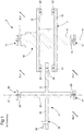
- the magnetic escape wheel 4 comprises a shaft 8 having at its two ends two pivots 10 and 11 respectively arranged in two bearings 12 and 13 which define an axis of rotation 9 for the escape wheel.
- This escape wheel conventionally comprises a pinion 14 for its drive by a barrel, generally via a kinematic chain formed of at least one mobile.
- the two magnetic tracks 20, 21 and said at least one pallet 34 together form a magnetic system of the watch movement incorporating the magnetic escapement in question.
- the permanent magnets forming the two magnetic tracks and said at least one permanent magnet forming said at least one magnetic paddle are called 'functional permanent magnets' by the fact that they actively participate in the magnetic system provided for contactless coupling of the wheel. escapement with anchor.
- the magnetic anchor further comprises a shaft 26 having at its two ends two pivots 28 and 29 respectively arranged in two bearings 30 and 31 which define an axis of rotation 27 for the magnetic anchor.
- the magnetic anchor comprises an arm 32 connecting the magnetic pallet 34 to the shaft 26 and a rod 36 having at its end free a fork 38 and a dart 39.
- the external magnetic field B Ext has a non-zero component Bx.
- the magnetic tracks or magnet tracks 20, 21 both have a magnetization axis oriented along the Z axis and having the same direction, so the overall magnetic moment of the functional permanent magnets forming these two magnetic tracks or magnet tracks has a direction along the Z axis.
- each functional magnet carried by the escape wheel has a magnetic moment which can be defined mathematically as being the integral of the magnetization over the entire volume of this functional magnet.
- all of the functional permanent magnets of the escape wheel namely those forming the two magnetic tracks, have an overall magnetic moment oriented along the axis of rotation 9 of the escape wheel, c ' that is to say along the Z axis.
- an external magnetic field B Ext passes through the escape wheel, the overall magnetic moment of that escape wheel tends to align with the external magnetic field, similar to the needle of a compass. .
- an external magnetic field having a component Bx generates, for a rotating element having an overall magnetic moment whose component along its axis of rotation is non-zero, a moment of force whose vector has a component M Y , along the Y axis, which is non-zero.
- an external magnetic field having a non-zero radial component, relative to the axis of rotation of a rotating element provided with magnets, generates, when this rotating element exhibits an overall magnetic moment, the component of which along its axis of rotation is non-zero, a moment of force on the rotating element whose vector has a non-zero radial component M XY in the XY plane. From this radial component M XY of the moment of force generated by the external magnetic field results a radial force of each of the two pivots 10, 11 on the lateral surface of the hole of the respective bearing 12, 13 in which this pivot is arranged.
- the escape wheel 42 forming a rotating element, comprises a permanent magnet 44 for compensating the overall magnetic moment that all of the functional permanent magnets of this escape wheel have.
- the compensation permanent magnet is arranged so that the vector addition of said overall magnetic moment with the compensation magnetic moment of this compensation permanent magnet gives either a zero vector or a resulting vector whose norm is lower to the norm of the global magnetic moment.
- the norm of said resulting vector is expected to be less than half of the norm of said overall magnetic moment.
- the permanent compensation magnet can interact with other elements of the watch movement and generate a certain disturbance in the operation of these other elements or components carrying the rotating element in question or these other elements.
- the watch designer chooses not to fully compensate a parasitic force torque which is applied to the rotating element considered and resulting from a coupling of said overall magnetic moment with a uniform external magnetic field.
- the compensating magnetic moment is oriented in the general direction (Z axis) of said overall magnetic moment and has a direction opposite to that of this overall magnetic moment.
- the norm of the compensating magnetic moment is expected to be substantially equal to the norm of the overall magnetic moment.
- the permanent compensation magnet 44 is arranged so as not to prevent all the functional permanent magnets of the escape wheel 42 from fulfilling their respective functions in the magnetic coupling system of this escape wheel with a magnetic anchor. , for example similar to the magnetic anchor 6 of the Figure 2 .
- the permanent compensation magnet is an annular magnet which is arranged around the pivoted shaft 8.
- the annular compensation magnet is arranged under the two plates 16 and 18 on the side opposite that of the drive pinion 14.
- the escape wheel 52 comprises a permanent compensation magnet 44A which is also of annular shape and arranged around the shaft 8A of this escape wheel, against a shoulder of this shaft, but this magnet 44A is arranged here between the two plates 16 and 18 respectively carrying the two magnetized tracks 20 and 22. More particularly, the magnet 44A is arranged midway between the two plates. This configuration is more optimal in the case where the external magnetic field which passes through the magnetic escape wheel is not very uniform.
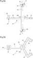
- FIG. 5A and 5B There is shown an embodiment of the invention which relates to a magnetic anchor 62, which forms a rotating element provided with at least one functional permanent magnet.
- This magnetic anchor apart from the permanent compensation magnet 44B, is similar to that of the Figure 1 .
- the Figure 5A is cut in a general plane comprising the axis of rotation 27 and the longitudinal axis of the rod 36.
- the Figure 5B is a top view, without the representation of the upper landing.
- the magnetic anchor is similar to a classic Swiss type anchor. It comprises two magnetic paddles formed respectively by two permanent magnets 34 and 35 which are respectively arranged at the ends of two arms 32 and 33.
- the two magnetic paddles constitute the set of functional permanent magnets of the anchor 62.
- the permanent magnets 34 and 35 both have an axial magnetization with the same polarity, so that the set of functional permanent magnets has, as for the magnetic escape wheel described above, an overall magnetic moment oriented along the Z axis (orientation of the rotation axis).
- the permanent compensation magnet 44B has a magnetic axis along the axis of rotation and a reverse polarity with respect to that of the two permanent magnets 34, 35.
- the intensity of the magnetic field generated by the compensating permanent magnet 44B is selected in a manner similar to that previously described for the compensating permanent magnet 44, 44A of the escape wheel 42 or 52.
- the magnet 44B is also ring-shaped and arranged around the shaft 26 of the anchor. Preferably, this magnet 44B is arranged along the shaft 26 as close as possible to the general plane perpendicular to the axis of rotation and comprising the two magnets 34, 35 which participate in the magnetic system for coupling the magnetic anchor with a escape wheel, for example similar to that shown in Figures 3 , 4 .
Landscapes
- Physics & Mathematics (AREA)
- General Physics & Mathematics (AREA)
- Electromagnetism (AREA)
- Magnetic Bearings And Hydrostatic Bearings (AREA)
Abstract
Description
- L'invention concerne les mouvements horlogers munis d'au moins un élément tournant participant à au moins un système magnétique du mouvement horloger, cet élément tournant étant muni d'au moins un aimant permanent fonctionnel formant ledit au moins un système magnétique.
- Par 'élément tournant', on comprend un élément agencé dans le mouvement horloger de manière à pouvoir subir une certaine rotation, dans un sens donné ou dans les deux sens. Ainsi, cette expression s'applique par exemple autant à une roue d'échappement qu'à un balancier, une ancre ou une bascule.
- En particulier, l'invention concerne une pièce d'horlogerie, notamment une montre-bracelet, comportant au moins un mouvement horloger du type décrit ci-dessus.
- Divers mouvements horlogers comprenant au moins un système magnétique intervenant dans le fonctionnement du mouvement horloger sont connus de l'art antérieur. On connaît notamment des mouvements horlogers équipés d'un échappement magnétique formé par un système magnétique auquel participent au moins un aimant porté par une ancre et au moins un aimant porté par une roue d'échappement. De tels échappements magnétiques sont notamment décrits dans les documents
EP_2887157 ,EP_2911015 ,EP_3128379 ,EP_3217227 etCH_712154 CH_709031 CH_713070 - Le document
BE 635 519 - L'ensemble des aimants permanents fonctionnels d'un l'élément tournant, qui forme un échappement magnétique d'un mouvement horloger, présente souvent un moment magnétique global dont la composante selon l'axe de rotation de l'élément tournant est non nulle. Ceci pose un problème technique dans un environnement où règne un champ magnétique extérieur. En effet, dans ce cas, la présence d'un magnétique extérieur, dans la mesure où il n'est pas parallèle à l'axe de rotation de l'élément tournant, a pour effet d'engendrer un moment de force sur cet élément tournant dont le vecteur a une composante perpendiculaire à l'axe de rotation. Cette composante perpendiculaire du moment de force tend à faire tourner l'arbre de l'élément tournant autour d'un axe perpendiculaire à l'axe de rotation, ce qui presse les deux pivots de l'élément tournant contre la surface latérale du trou de chacun des deux paliers respectifs. Il en résulte donc un frottement qui consomme de l'énergie et qui croît avec l'intensité du champ magnétique externe. Si cette intensité devient importante, il est même possible que le couple de force parasite engendré par le champ magnétique externe sur l'élément tournant puisse le stopper. Après avoir mis en évidence le problème technique susmentionné, les inventeurs propose une solution technique permettant de le résoudre.
- Ainsi, l'invention concerne un mouvement horloger comprenant un échappement magnétique formé par une roue d'échappement et une ancre dont au moins une participe à un système magnétique de cet échappement magnétique et est munie d'au moins un aimant permanent fonctionnel formant le système magnétique, l'ensemble des aimants permanents fonctionnels de la roue d'échappement ou/et l'ensemble des aimants permanents fonctionnels de l'ancre ayant un moment magnétique global orienté selon une direction générale de magnétisation. Selon l'invention, la roue d'échappement ou/et l'ancre comprend /comprennent chacune en outre au moins un aimant permanent de compensation dudit moment magnétique global, ledit au moins un aimant permanent de compensation étant agencé de manière que l'addition vectorielle du moment magnétique global avec le moment magnétique de compensation donne soit un vecteur nul, soit un vecteur résultant dont la norme est inférieure à la norme du moment magnétique global.
- Dans une variante avantageuse, ledit au moins un aimant permanent de compensation est agencé de manière que, le cas échéant, la norme dudit vecteur résultant soit inférieure à la moitié de la norme du moment magnétique global.
- Dans une variante préférée, le moment magnétique de compensation est orienté selon la direction générale de magnétisation et présente un sens opposé à celui dudit moment magnétique global. De plus, la norme du moment magnétique de compensation est sensiblement égale à la norme du moment magnétique global.
- Grâce au moment magnétique de compensation dudit au moins un aimant permanent de compensation, un couple de force parasite, engendré par le moment magnétique global de l'ensemble des aimants permanents fonctionnels dans un champ magnétique extérieur uniforme et s'appliquant à l'élément tournant considéré (la roue d'échappement ou l'ancre), est au moins partiellement compensé par un couple de force de compensation engendré par le moment magnétique de compensation dans le champ magnétique extérieur uniforme. Dans la variante préférée, le couple de force total agissant sur l'élément tournant, lorsqu'un champ magnétique extérieur uniforme traverse le mouvement horloger, a une faible valeur qui peut être sensiblement nulle. On diminue ainsi fortement, voire on annule sensiblement des forces de frottement parasites qui agiraient, en l'absence dudit au moins un aimant permanent de compensation, sur les deux pivots de l'élément tournant dans leurs paliers respectifs en présence d'un champ magnétique externe uniforme engendrant sur l'ensemble des aimants permanents fonctionnels un couple de force parasite dont le vecteur n'est pas axial.
- L'invention sera décrite ci-après de manière plus détaillée à l'aide des dessins annexés, donnés à titre d'exemples nullement limitatifs, dans lesquels :
- La
Figure 1 représente, de manière simplifiée, un échappement magnétique de l'art antérieur présentant le problème technique identifié; - La
Figure 2 montre les forces agissant sur la roue d'échappement de laFigure 1 en présence d'un champ magnétique externe au mouvement horloger ayant une composante perpendiculaire à l'axe de rotation; - La
Figure 3 est une vue en coupe simplifiée d'une roue d'échappement magnétique selon l'invention; - La
Figure 4 est une vue en coupe simplifiée d'une variante de roue d'échappement magnétique selon l'invention; et - Les
Figures 5A et 5B sont des vues simplifiées respectivement en coupe et de dessus d'une ancre magnétique selon l'invention. - A la
Figure 1 est représenté, de manière simplifiée, un échappement magnétique 2 équipant un mouvement horloger de l'art antérieur et formé par une roue d'échappement 4 et une ancre 6. On a représenté ce mouvement horloger dans un champ magnétique externe BExt. La roue d'échappement magnétique 4 comprend un arbre 8 ayant à ses deux extrémités deux pivots 10 et 11 respectivement agencés dans deux paliers 12 et 13 qui définissent un axe de rotation 9 pour la roue d'échappement. Cette roue d'échappement comprend de manière classique un pignon 14 pour son entraînement par un barillet, généralement via une chaîne cinématique formée d'au moins un mobile. Elle comprend en outre deux plateaux amagnétiques 16 et 18 portant respectivement deux pistes magnétiques annulaires 20 et 22, formées par des aimants permanents, qui sont couplées magnétiquement, en répulsion, à au moins une palette magnétique 34, formée également par au moins un aimant permanent, équipant l'ancre magnétique 6. Les deux pistes magnétiques 20, 21 et ladite au moins une palette 34 forment ensemble un système magnétique du mouvement horloger incorporant l'échappement magnétique considéré. Ainsi les aimants permanents formant les deux pistes magnétiques et ledit au moins un aimant permanent formant ladite au moins une palette magnétique sont nommés 'aimants permanents fonctionnels' par le fait qu'ils participent activement au système magnétique prévu pour coupler sans contact la roue d'échappement avec l'ancre. - L'ancre magnétique comprend encore un arbre 26 ayant à ses deux extrémités deux pivots 28 et 29 respectivement agencés dans deux paliers 30 et 31 qui définissent un axe de rotation 27 pour l'ancre magnétique. De manière classique, l'ancre magnétique comprend un bras 32 reliant la palette magnétique 34 à l'arbre 26 et une baguette 36 présentant à son extrémité libre une fourchette 38 et un dard 39. On remarquera que, dans le cas où l'ancre comprend deux palettes magnétiques portées respectivement par deux bras à la manière d'une ancre suisse, la coupe de la
Figure 1 est alors effectuée selon une ligne brisée passant par les deux axes de rotation 9 et 27 et par une 34 des deux palettes magnétiques qui est hors du plan géométrique comprenant les deux axes de rotation. - A la
Figure 2 est représentée une coupe de la roue d'échappement 4 dans le plan X-Z. Pour exposer visuellement le problème technique déjà indiqué dans le résumé de l'invention, le champ magnétique extérieur BExt présente une composante Bx non nulle. Les pistes magnétiques ou pistes aimantées 20, 21 ont toutes deux un axe d'aimantation orienté selon l'axe Z et présentant un même sens, de sorte le moment magnétique global des aimants permanents fonctionnels formant ces deux pistes magnétiques ou pistes aimantées présente une direction selon l'axe Z. On notera que chaque aimant fonctionnel porté par la roue d'échappement présente un moment magnétique que l'on peut définir de façon mathématique comme étant l'intégrale de la magnétisation sur tout le volume de cet aimant fonctionnel. Dans le cas représenté, l'ensemble des aimants permanents fonctionnels de la roue d'échappement, à savoir ceux formant les deux pistes magnétiques, ont un moment magnétique global orienté selon l'axe de rotation 9 de la roue d'échappement, c'est-à-dire selon l'axe Z. - Comme indiqué, on considère ici un cas où la roue d'échappement se trouve dans un champ magnétique extérieur ayant une composante Bx non nulle. Lorsqu'un champ magnétique externe BExt passe au travers de la roue d'échappement, le moment magnétique global de cette roue d'échappement tend à s'aligner avec le champ magnétique externe, de façon analogue à l'aiguille d'une boussole. En d'autres termes, un champ magnétique extérieur ayant une composante Bx engendre, pour un élément tournant ayant un moment magnétique global dont la composante selon son axe de rotation est non nulle, un moment de force dont le vecteur présente une composante MY, selon l'axe Y, qui est non nulle. Plus généralement, un champ magnétique extérieur ayant une composante radiale non nulle, relativement à l'axe de rotation d'un élément tournant muni d'aimants, engendre, lorsque cet élément tournant présente un moment magnétique global dont la composante selon son axe de rotation est non nulle, un moment de force sur l'élément tournant dont le vecteur présente une composante radiale MXY non nulle dans le plan X-Y. De cette composante radiale MXY du moment de force engendré par le champ magnétique extérieur résulte une force radiale de chacun des deux pivots 10, 11 sur la surface latérale du trou du palier respectif 12, 13 dans lequel ce pivot est agencé. Les paliers exercent alors en réaction une force normale FN ; ce qui engendre alors un frottement continu des pivots dans les paliers et augmente le frottement global de ces pivots dans leurs paliers respectifs. Ceci représente un problème en terme de fonctionnement de l'échappement magnétique et une perte d'énergie mécanique, problème qui augmente avec l'intensité du champ magnétique extérieur et qui peut aller jusqu'à bloquer l'échappement magnétique en question.
- A la
Figure 3 est représenté un mode de réalisation de l'invention pour un mouvement horloger équipé d'une roue d'échappement similaire à celle laFigure 2 . Les références déjà décrites précédemment ne seront pas décrite à nouveau ici. La roue d'échappement 42, formant un élément tournant, comprend un aimant permanent 44 de compensation du moment magnétique global que présente l'ensemble des aimants permanents fonctionnels de cette roue d'échappement. De manière générale, l'aimant permanent de compensation est agencé de manière que l'addition vectorielle dudit moment magnétique global avec le moment magnétique de compensation de cet aimant permanent de compensation donne soit un vecteur nul, soit un vecteur résultant dont la norme est inférieure à la norme du moment magnétique global. Dans une variante, la norme dudit vecteur résultant est prévue inférieure à la moitié de la norme dudit moment magnétique global. On notera que l'aimant permanent de compensation peut avoir une interaction avec d'autres éléments du mouvement horloger et engendré une certaine perturbation sur le fonctionnement de ces autres éléments ou de composants portant l'élément tournant considéré ou ces autres éléments. Ainsi, il est possible que le concepteur horloger choisisse de ne pas compenser entièrement un couple de force parasite qui s'applique sur l'élément tournant considéré et résultant d'un couplage dudit moment magnétique global avec un champ magnétique extérieur uniforme. - Dans une variante préférée, comme à la
Figure 3 , le moment magnétique de compensation est orienté selon la direction générale (axe Z) dudit moment magnétique global et présente un sens opposé à celui de ce moment magnétique global. Ensuite, la norme du moment magnétique de compensation est prévue sensiblement égale à la norme du moment magnétique global. Par 'norme', on comprend la longueur du vecteur considéré, c'est-à-dire la valeur absolue de cette longueur. On parle aussi parfois de l'intensité du vecteur. Ainsi, dans le présent texte, 'longueur', 'norme', 'intensité' et 'valeur (absolue)' pour un vecteur sont des synonymes. - L'aimant permanent de compensation 44 est agencé de manière à ne pas empêcher l'ensemble des aimants permanents fonctionnels de la roue d'échappement 42 de remplir leurs fonctions respectives dans le système magnétique de couplage de cette roue d'échappement avec une ancre magnétique, par exemple semblable à l'ancre magnétique 6 de la
Figure 2 . Dans une variante avantageuse, l'aimant permanent de compensation est un aimant de forme annulaire qui est agencé autour de l'arbre pivoté 8. Dans la variante représentée à laFigure 3 , l'aimant de compensation annulaire est agencé sous les deux plateaux 16 et 18 du côté opposé à celui du pignon d'entraînement 14. - A la
Figure 4 est représentée une variante préférée. Dans cette variante préférée, la roue d'échappement 52 comprend un aimant permanent de compensation 44A qui est également de forme annulaire et agencé autour de l'arbre 8A de cette roue d'échappement, contre un épaulement de cet arbre, mais cet aimant 44A est agencé ici entre les deux plateaux 16 et 18 portant respectivement les deux pistes aimantées 20 et 22. Plus particulièrement, l'aimant 44A est agencé à mi-distance des deux plateaux. Cette configuration est plus optimale dans le cas où le champ magnétique extérieur qui traverse la roue d'échappement magnétique n'est pas bien uniforme. - Aux
Figures 5A et 5B est représenté un mode de réalisation de l'invention qui concerne une ancre magnétique 62, laquelle forme un élément tournant muni d'au moins un aimant permanent fonctionnel. Cette ancre magnétique, hormis l'aimant permanent de compensation 44B, est similaire à celle de laFigure 1 . Ainsi, cette ancre magnétique ne sera pas décrite à nouveau ici en détails. LaFigure 5A est coupe dans un plan général comprenant l'axe de rotation 27 et l'axe longitudinal de la baguette 36. LaFigure 5B est une vue de dessus, sans la représentation du palier supérieur. Sur cetteFigure 5B , on voit que l'ancre magnétique s'apparente à une ancre classique de type suisse. Elle comprend deux palettes magnétiques formées respectivement par deux aimants permanents 34 et 35 qui sont agencées respectivement aux extrémités de deux bras 32 et 33. Les deux palettes magnétiques constituent l'ensemble des aimants permanents fonctionnels de l'ancre 62. Les aimants permanents 34 et 35 ont tous deux une aimantation axiale avec une même polarité, de sorte que l'ensemble des aimants permanents fonctionnels présente, comme pour la roue d'échappement magnétique décrite précédemment, un moment magnétique global orienté selon l'axe Z (orientation de l'axe de rotation). Ainsi, selon une variante préférée de l'invention, l'aimant permanent de compensation 44B présente un axe magnétique selon l'axe de rotation et une polarité inversée par rapport à celle des deux aimants permanents 34, 35. - L'intensité du champ magnétique généré par l'aimant permanent de compensation 44B est sélectionnée de manière semblable à celle décrite précédemment pour l'aimant permanent de compensation 44, 44A de la roue d'échappement 42 ou 52. L'aimant 44B est aussi de forme annulaire et agencé autour de l'arbre 26 de l'ancre. De préférence, cet aimant 44B est agencé le long de l'arbre 26 au plus proche du plan général perpendiculaire à l'axe de rotation et comprenant les deux aimants 34, 35 qui participent au système magnétique de couplage de l'ancre magnétique avec une roue d'échappement, par exemple similaire à celle représentée aux
Figures 3 ,4 .
Claims (9)
- Mouvement horloger comprenant un échappement magnétique formé en partie par une roue d'échappement (42 ; 52) qui participe à un système magnétique de cet échappement magnétique et qui est munie d'au moins un aimant permanent fonctionnel (20, 22), l'ensemble des aimants permanents fonctionnels de la roue d'échappement ayant un moment magnétique global orienté selon une direction générale de magnétisation, cette roue d'échappement comprenant en outre au moins un aimant permanent (44 ; 44A) de compensation dudit moment magnétique global, ledit au moins un aimant permanent de compensation étant agencé de manière que l'addition vectorielle du moment magnétique global avec le moment magnétique de compensation donne soit un vecteur nul, soit un vecteur résultant dont la norme est inférieure à la norme du moment magnétique global.
- Mouvement horloger selon la revendication 1, dans lequel la roue d'échappement comprend au moins un plateau (16) porté par un arbre pivoté (8, 8A), ce plateau étant agencé perpendiculairement audit axe de rotation (9) et portant à sa périphérie des aimants permanents fonctionnels (20) parmi ledit ensemble d'aimants permanents fonctionnels, ledit au moins un aimant permanent de compensation (44, 44A) entourant ledit arbre pivoté.
- Mouvement horloger selon la revendication 2, dans lequel la roue d'échappement comprend deux plateaux (16, 18) en matériau non magnétique qui sont portés par ledit arbre pivoté, ces deux plateaux étant agencé à distance l'un de l'autre perpendiculairement audit axe de rotation (9) et portant chacun à sa périphérie, du côté d'un espace intermédiaire entre les deux plateaux, des aimants permanents fonctionnels (20, 22) formant ledit ensemble d'aimants permanents fonctionnels ; caractérisé en ce que ledit aimant permanent de compensation (44A) est agencé entre les deux plateaux sensiblement à une même distance axiale de ceux-ci.
- Mouvement horloger comprenant un échappement magnétique formé en partie par une ancre (62) qui participe à un système magnétique de cet échappement magnétique, cette ancre comprenant au moins une palette magnétique formée chacune par un aimant permanent fonctionnel (34, 35), l'ensemble des aimants permanents fonctionnels de cette ancre ayant un moment magnétique global orienté selon une direction générale de magnétisation, cette ancre comprenant en outre au moins un aimant permanent (44B) de compensation dudit moment magnétique global, ledit au moins un aimant permanent de compensation (44B) étant agencé de manière que l'addition vectorielle du moment magnétique global avec le moment magnétique de compensation donne soit un vecteur nul, soit un vecteur résultant dont la norme est inférieure à la norme du moment magnétique global.
- Mouvement horloger selon la revendication 4, dans lequel ledit au moins un aimant permanent de compensation (44B) entoure un arbre pivoté (26) de l'ancre.
- Mouvement horloger selon une quelconque des revendications précédentes, caractérisé en ce que ledit au moins un aimant permanent de compensation est agencé de manière que, le cas échéant, ladite norme dudit vecteur résultant soit inférieure à la moitié de ladite norme du moment magnétique global.
- Mouvement horloger selon une quelconque des revendications précédentes, dans lequel ledit moment magnétique de compensation est orienté selon ladite direction générale de magnétisation et présente un sens opposé à celui dudit moment magnétique global, la norme du moment magnétique de compensation étant sensiblement égale à ladite norme du moment magnétique global.
- Mouvement horloger selon une quelconque des revendications précédentes, caractérisé en ce que ledit au moins un aimant permanent de compensation est agencé de manière à ne pas empêcher ledit ensemble des aimants permanents fonctionnels de remplir leurs fonctions respectives dans ledit au moins un système magnétique.
- Pièce d'horlogerie, notamment montre-bracelet, comprenant un mouvement horloger selon une quelconque des revendications précédentes.
Applications Claiming Priority (1)
| Application Number | Priority Date | Filing Date | Title |
|---|---|---|---|
| EP19182711 | 2019-06-26 |
Publications (2)
| Publication Number | Publication Date |
|---|---|
| EP3757682A1 true EP3757682A1 (fr) | 2020-12-30 |
| EP3757682B1 EP3757682B1 (fr) | 2022-03-09 |
Family
ID=67105776
Family Applications (1)
| Application Number | Title | Priority Date | Filing Date |
|---|---|---|---|
| EP20165957.0A Active EP3757682B1 (fr) | 2019-06-26 | 2020-03-26 | Mouvement horloger comprenant un échappement magnétique |
Country Status (1)
| Country | Link |
|---|---|
| EP (1) | EP3757682B1 (fr) |
Citations (9)
| Publication number | Priority date | Publication date | Assignee | Title |
|---|---|---|---|---|
| BE635519A (fr) | 1962-07-30 | 1963-11-18 | ||
| FR1508525A (fr) * | 1966-01-21 | 1968-01-05 | Gen Electric | Perfectionnements aux aimants oscillants pour horloge à fil de torsion |
| EP2887157A1 (fr) | 2013-12-23 | 2015-06-24 | The Swatch Group Research and Development Ltd. | Echappement optimisé |
| CH709031A2 (fr) | 2013-12-23 | 2015-06-30 | Swatch Group Res & Dev Ltd | Dispositif régulateur de la vitesse angulaire d'un mobile dans un mouvement horloger comprenant un échappement magnétique. |
| EP2911015A2 (fr) | 2013-12-23 | 2015-08-26 | The Swatch Group Research and Development Ltd. | Echappement naturel |
| EP3128379A1 (fr) | 2015-08-04 | 2017-02-08 | The Swatch Group Research and Development Ltd. | Echappement avec roue d'echappement avec rampes de champ et dispositif anti-retour |
| CH712154A2 (fr) | 2016-02-18 | 2017-08-31 | Swatch Group Res & Dev Ltd | Mobile d'échappement magnétique d'horlogerie. |
| EP3217227A1 (fr) | 2016-03-11 | 2017-09-13 | The Swatch Group Research and Development Ltd. | Mecanisme regulateur d'horlogerie a echappement magnetique optimise |
| CH713070A2 (fr) | 2016-10-25 | 2018-04-30 | Swatch Group Res & Dev Ltd | Mouvement mécanique d'horlogerie comportant un mécanisme résonateur à lames et un mécanisme d'échappement magnétique. |
-
2020
- 2020-03-26 EP EP20165957.0A patent/EP3757682B1/fr active Active
Patent Citations (9)
| Publication number | Priority date | Publication date | Assignee | Title |
|---|---|---|---|---|
| BE635519A (fr) | 1962-07-30 | 1963-11-18 | ||
| FR1508525A (fr) * | 1966-01-21 | 1968-01-05 | Gen Electric | Perfectionnements aux aimants oscillants pour horloge à fil de torsion |
| EP2887157A1 (fr) | 2013-12-23 | 2015-06-24 | The Swatch Group Research and Development Ltd. | Echappement optimisé |
| CH709031A2 (fr) | 2013-12-23 | 2015-06-30 | Swatch Group Res & Dev Ltd | Dispositif régulateur de la vitesse angulaire d'un mobile dans un mouvement horloger comprenant un échappement magnétique. |
| EP2911015A2 (fr) | 2013-12-23 | 2015-08-26 | The Swatch Group Research and Development Ltd. | Echappement naturel |
| EP3128379A1 (fr) | 2015-08-04 | 2017-02-08 | The Swatch Group Research and Development Ltd. | Echappement avec roue d'echappement avec rampes de champ et dispositif anti-retour |
| CH712154A2 (fr) | 2016-02-18 | 2017-08-31 | Swatch Group Res & Dev Ltd | Mobile d'échappement magnétique d'horlogerie. |
| EP3217227A1 (fr) | 2016-03-11 | 2017-09-13 | The Swatch Group Research and Development Ltd. | Mecanisme regulateur d'horlogerie a echappement magnetique optimise |
| CH713070A2 (fr) | 2016-10-25 | 2018-04-30 | Swatch Group Res & Dev Ltd | Mouvement mécanique d'horlogerie comportant un mécanisme résonateur à lames et un mécanisme d'échappement magnétique. |
Also Published As
| Publication number | Publication date |
|---|---|
| EP3757682B1 (fr) | 2022-03-09 |
Similar Documents
| Publication | Publication Date | Title |
|---|---|---|
| EP3545367B1 (fr) | Résonateur rotatif à guidage flexible entretenu par un échappement libre à ancre | |
| EP2762985B1 (fr) | Pivotement magnétique ou électrostatique de mobile d'horlogerie | |
| EP3106933B1 (fr) | Dispositif magnétique de pivotement d'un arbre dans un mouvement horloger | |
| EP2799937B1 (fr) | Corps d'amortisseur d'un balancier d'un oscillateur d'horlogerie | |
| EP3172626B1 (fr) | Pivot à lame | |
| EP3246764B1 (fr) | Dispositif antichoc pour un mouvement horloger | |
| EP3839651B1 (fr) | Oscillateur horloger mécanique a guidage flexible | |
| CH698081B1 (fr) | Virole d'horlogerie, ensemble virole-spiral et balancier-spiral. | |
| EP3792700A1 (fr) | Oscillateur horloger a pivot flexible | |
| EP3185083B1 (fr) | Mecanisme horloger mecanique avec un echappement a ancre | |
| EP3757682B1 (fr) | Mouvement horloger comprenant un échappement magnétique | |
| WO2012084382A1 (fr) | Mobile d'horlogerie a guidage peripherique | |
| EP3109712B1 (fr) | Dispositif magnétique de pivotement d'un arbre dans un mouvement horloger | |
| CH716354A2 (fr) | Mouvement horloger comprenant un échappement magnétique. | |
| EP2771743B1 (fr) | Oscillateur de mouvement horloger | |
| CH705464B1 (fr) | Virole de fixation d'un spiral d'horlogerie. | |
| EP2887153A1 (fr) | Dispositif de centrage magnétique | |
| EP0012460B1 (fr) | Stator monobloc pour moteur pas à pas d'horlogerie | |
| EP2653938A1 (fr) | Balancier d'horlogerie | |
| CH711965A2 (fr) | Mouvement horloger mécanique avec un échappement à ancre. | |
| WO2024074517A1 (fr) | Axe horloger | |
| EP4202564A1 (fr) | Mouvement mecanique horloger comprenant un balancier pivote magnetiquement | |
| EP3206090A1 (fr) | Mouvement d'horlogerie comportant deux balanciers | |
| EP4535091A1 (fr) | Mouvement horloger muni d'un dispositif de réglage de la fréquence d'un résonateur mécanique | |
| EP3757685A1 (fr) | Mobile inertiel pour resonateur d'horlogerie avec dispositif d'interaction magnetique insensible au champ magnetique externe |
Legal Events
| Date | Code | Title | Description |
|---|---|---|---|
| PUAI | Public reference made under article 153(3) epc to a published international application that has entered the european phase |
Free format text: ORIGINAL CODE: 0009012 |
|
| STAA | Information on the status of an ep patent application or granted ep patent |
Free format text: STATUS: THE APPLICATION HAS BEEN PUBLISHED |
|
| AK | Designated contracting states |
Kind code of ref document: A1 Designated state(s): AL AT BE BG CH CY CZ DE DK EE ES FI FR GB GR HR HU IE IS IT LI LT LU LV MC MK MT NL NO PL PT RO RS SE SI SK SM TR |
|
| AX | Request for extension of the european patent |
Extension state: BA ME |
|
| STAA | Information on the status of an ep patent application or granted ep patent |
Free format text: STATUS: REQUEST FOR EXAMINATION WAS MADE |
|
| 17P | Request for examination filed |
Effective date: 20210630 |
|
| RBV | Designated contracting states (corrected) |
Designated state(s): AL AT BE BG CH CY CZ DE DK EE ES FI FR GB GR HR HU IE IS IT LI LT LU LV MC MK MT NL NO PL PT RO RS SE SI SK SM TR |
|
| GRAP | Despatch of communication of intention to grant a patent |
Free format text: ORIGINAL CODE: EPIDOSNIGR1 |
|
| STAA | Information on the status of an ep patent application or granted ep patent |
Free format text: STATUS: GRANT OF PATENT IS INTENDED |
|
| RIC1 | Information provided on ipc code assigned before grant |
Ipc: G04B 15/08 20060101ALI20211111BHEP Ipc: G04B 13/02 20060101ALI20211111BHEP Ipc: G04B 17/28 20060101ALI20211111BHEP Ipc: G04B 17/20 20060101ALI20211111BHEP Ipc: G04C 5/00 20060101ALI20211111BHEP Ipc: G04B 15/14 20060101AFI20211111BHEP |
|
| INTG | Intention to grant announced |
Effective date: 20211201 |
|
| GRAS | Grant fee paid |
Free format text: ORIGINAL CODE: EPIDOSNIGR3 |
|
| GRAA | (expected) grant |
Free format text: ORIGINAL CODE: 0009210 |
|
| STAA | Information on the status of an ep patent application or granted ep patent |
Free format text: STATUS: THE PATENT HAS BEEN GRANTED |
|
| AK | Designated contracting states |
Kind code of ref document: B1 Designated state(s): AL AT BE BG CH CY CZ DE DK EE ES FI FR GB GR HR HU IE IS IT LI LT LU LV MC MK MT NL NO PL PT RO RS SE SI SK SM TR |
|
| REG | Reference to a national code |
Ref country code: CH Ref legal event code: EP Ref country code: AT Ref legal event code: REF Ref document number: 1474678 Country of ref document: AT Kind code of ref document: T Effective date: 20220315 |
|
| REG | Reference to a national code |
Ref country code: IE Ref legal event code: FG4D Free format text: LANGUAGE OF EP DOCUMENT: FRENCH |
|
| REG | Reference to a national code |
Ref country code: DE Ref legal event code: R096 Ref document number: 602020002099 Country of ref document: DE |
|
| REG | Reference to a national code |
Ref country code: LT Ref legal event code: MG9D |
|
| REG | Reference to a national code |
Ref country code: NL Ref legal event code: MP Effective date: 20220309 |
|
| PG25 | Lapsed in a contracting state [announced via postgrant information from national office to epo] |
Ref country code: SE Free format text: LAPSE BECAUSE OF FAILURE TO SUBMIT A TRANSLATION OF THE DESCRIPTION OR TO PAY THE FEE WITHIN THE PRESCRIBED TIME-LIMIT Effective date: 20220309 Ref country code: RS Free format text: LAPSE BECAUSE OF FAILURE TO SUBMIT A TRANSLATION OF THE DESCRIPTION OR TO PAY THE FEE WITHIN THE PRESCRIBED TIME-LIMIT Effective date: 20220309 Ref country code: NO Free format text: LAPSE BECAUSE OF FAILURE TO SUBMIT A TRANSLATION OF THE DESCRIPTION OR TO PAY THE FEE WITHIN THE PRESCRIBED TIME-LIMIT Effective date: 20220609 Ref country code: LT Free format text: LAPSE BECAUSE OF FAILURE TO SUBMIT A TRANSLATION OF THE DESCRIPTION OR TO PAY THE FEE WITHIN THE PRESCRIBED TIME-LIMIT Effective date: 20220309 Ref country code: HR Free format text: LAPSE BECAUSE OF FAILURE TO SUBMIT A TRANSLATION OF THE DESCRIPTION OR TO PAY THE FEE WITHIN THE PRESCRIBED TIME-LIMIT Effective date: 20220309 Ref country code: BG Free format text: LAPSE BECAUSE OF FAILURE TO SUBMIT A TRANSLATION OF THE DESCRIPTION OR TO PAY THE FEE WITHIN THE PRESCRIBED TIME-LIMIT Effective date: 20220609 |
|
| REG | Reference to a national code |
Ref country code: AT Ref legal event code: MK05 Ref document number: 1474678 Country of ref document: AT Kind code of ref document: T Effective date: 20220309 |
|
| PG25 | Lapsed in a contracting state [announced via postgrant information from national office to epo] |
Ref country code: LV Free format text: LAPSE BECAUSE OF FAILURE TO SUBMIT A TRANSLATION OF THE DESCRIPTION OR TO PAY THE FEE WITHIN THE PRESCRIBED TIME-LIMIT Effective date: 20220309 Ref country code: GR Free format text: LAPSE BECAUSE OF FAILURE TO SUBMIT A TRANSLATION OF THE DESCRIPTION OR TO PAY THE FEE WITHIN THE PRESCRIBED TIME-LIMIT Effective date: 20220610 Ref country code: FI Free format text: LAPSE BECAUSE OF FAILURE TO SUBMIT A TRANSLATION OF THE DESCRIPTION OR TO PAY THE FEE WITHIN THE PRESCRIBED TIME-LIMIT Effective date: 20220309 |
|
| PG25 | Lapsed in a contracting state [announced via postgrant information from national office to epo] |
Ref country code: NL Free format text: LAPSE BECAUSE OF FAILURE TO SUBMIT A TRANSLATION OF THE DESCRIPTION OR TO PAY THE FEE WITHIN THE PRESCRIBED TIME-LIMIT Effective date: 20220309 |
|
| PG25 | Lapsed in a contracting state [announced via postgrant information from national office to epo] |
Ref country code: SM Free format text: LAPSE BECAUSE OF FAILURE TO SUBMIT A TRANSLATION OF THE DESCRIPTION OR TO PAY THE FEE WITHIN THE PRESCRIBED TIME-LIMIT Effective date: 20220309 Ref country code: SK Free format text: LAPSE BECAUSE OF FAILURE TO SUBMIT A TRANSLATION OF THE DESCRIPTION OR TO PAY THE FEE WITHIN THE PRESCRIBED TIME-LIMIT Effective date: 20220309 Ref country code: RO Free format text: LAPSE BECAUSE OF FAILURE TO SUBMIT A TRANSLATION OF THE DESCRIPTION OR TO PAY THE FEE WITHIN THE PRESCRIBED TIME-LIMIT Effective date: 20220309 Ref country code: PT Free format text: LAPSE BECAUSE OF FAILURE TO SUBMIT A TRANSLATION OF THE DESCRIPTION OR TO PAY THE FEE WITHIN THE PRESCRIBED TIME-LIMIT Effective date: 20220711 Ref country code: ES Free format text: LAPSE BECAUSE OF FAILURE TO SUBMIT A TRANSLATION OF THE DESCRIPTION OR TO PAY THE FEE WITHIN THE PRESCRIBED TIME-LIMIT Effective date: 20220309 Ref country code: EE Free format text: LAPSE BECAUSE OF FAILURE TO SUBMIT A TRANSLATION OF THE DESCRIPTION OR TO PAY THE FEE WITHIN THE PRESCRIBED TIME-LIMIT Effective date: 20220309 Ref country code: CZ Free format text: LAPSE BECAUSE OF FAILURE TO SUBMIT A TRANSLATION OF THE DESCRIPTION OR TO PAY THE FEE WITHIN THE PRESCRIBED TIME-LIMIT Effective date: 20220309 Ref country code: AT Free format text: LAPSE BECAUSE OF FAILURE TO SUBMIT A TRANSLATION OF THE DESCRIPTION OR TO PAY THE FEE WITHIN THE PRESCRIBED TIME-LIMIT Effective date: 20220309 |
|
| PG25 | Lapsed in a contracting state [announced via postgrant information from national office to epo] |
Ref country code: PL Free format text: LAPSE BECAUSE OF FAILURE TO SUBMIT A TRANSLATION OF THE DESCRIPTION OR TO PAY THE FEE WITHIN THE PRESCRIBED TIME-LIMIT Effective date: 20220309 Ref country code: IS Free format text: LAPSE BECAUSE OF FAILURE TO SUBMIT A TRANSLATION OF THE DESCRIPTION OR TO PAY THE FEE WITHIN THE PRESCRIBED TIME-LIMIT Effective date: 20220709 Ref country code: AL Free format text: LAPSE BECAUSE OF FAILURE TO SUBMIT A TRANSLATION OF THE DESCRIPTION OR TO PAY THE FEE WITHIN THE PRESCRIBED TIME-LIMIT Effective date: 20220309 |
|
| REG | Reference to a national code |
Ref country code: BE Ref legal event code: MM Effective date: 20220331 |
|
| REG | Reference to a national code |
Ref country code: DE Ref legal event code: R097 Ref document number: 602020002099 Country of ref document: DE |
|
| PLBE | No opposition filed within time limit |
Free format text: ORIGINAL CODE: 0009261 |
|
| STAA | Information on the status of an ep patent application or granted ep patent |
Free format text: STATUS: NO OPPOSITION FILED WITHIN TIME LIMIT |
|
| PG25 | Lapsed in a contracting state [announced via postgrant information from national office to epo] |
Ref country code: MC Free format text: LAPSE BECAUSE OF FAILURE TO SUBMIT A TRANSLATION OF THE DESCRIPTION OR TO PAY THE FEE WITHIN THE PRESCRIBED TIME-LIMIT Effective date: 20220309 Ref country code: LU Free format text: LAPSE BECAUSE OF NON-PAYMENT OF DUE FEES Effective date: 20220326 Ref country code: IE Free format text: LAPSE BECAUSE OF NON-PAYMENT OF DUE FEES Effective date: 20220326 Ref country code: DK Free format text: LAPSE BECAUSE OF FAILURE TO SUBMIT A TRANSLATION OF THE DESCRIPTION OR TO PAY THE FEE WITHIN THE PRESCRIBED TIME-LIMIT Effective date: 20220309 |
|
| 26N | No opposition filed |
Effective date: 20221212 |
|
| PG25 | Lapsed in a contracting state [announced via postgrant information from national office to epo] |
Ref country code: SI Free format text: LAPSE BECAUSE OF FAILURE TO SUBMIT A TRANSLATION OF THE DESCRIPTION OR TO PAY THE FEE WITHIN THE PRESCRIBED TIME-LIMIT Effective date: 20220309 Ref country code: BE Free format text: LAPSE BECAUSE OF NON-PAYMENT OF DUE FEES Effective date: 20220331 |
|
| P01 | Opt-out of the competence of the unified patent court (upc) registered |
Effective date: 20230615 |
|
| PG25 | Lapsed in a contracting state [announced via postgrant information from national office to epo] |
Ref country code: IT Free format text: LAPSE BECAUSE OF FAILURE TO SUBMIT A TRANSLATION OF THE DESCRIPTION OR TO PAY THE FEE WITHIN THE PRESCRIBED TIME-LIMIT Effective date: 20220309 |
|
| PG25 | Lapsed in a contracting state [announced via postgrant information from national office to epo] |
Ref country code: MK Free format text: LAPSE BECAUSE OF FAILURE TO SUBMIT A TRANSLATION OF THE DESCRIPTION OR TO PAY THE FEE WITHIN THE PRESCRIBED TIME-LIMIT Effective date: 20220309 Ref country code: CY Free format text: LAPSE BECAUSE OF FAILURE TO SUBMIT A TRANSLATION OF THE DESCRIPTION OR TO PAY THE FEE WITHIN THE PRESCRIBED TIME-LIMIT Effective date: 20220309 |
|
| PG25 | Lapsed in a contracting state [announced via postgrant information from national office to epo] |
Ref country code: HU Free format text: LAPSE BECAUSE OF FAILURE TO SUBMIT A TRANSLATION OF THE DESCRIPTION OR TO PAY THE FEE WITHIN THE PRESCRIBED TIME-LIMIT; INVALID AB INITIO Effective date: 20200326 |
|
| PG25 | Lapsed in a contracting state [announced via postgrant information from national office to epo] |
Ref country code: MT Free format text: LAPSE BECAUSE OF FAILURE TO SUBMIT A TRANSLATION OF THE DESCRIPTION OR TO PAY THE FEE WITHIN THE PRESCRIBED TIME-LIMIT Effective date: 20220309 |
|
| GBPC | Gb: european patent ceased through non-payment of renewal fee |
Effective date: 20240326 |
|
| PG25 | Lapsed in a contracting state [announced via postgrant information from national office to epo] |
Ref country code: GB Free format text: LAPSE BECAUSE OF NON-PAYMENT OF DUE FEES Effective date: 20240326 |
|
| PG25 | Lapsed in a contracting state [announced via postgrant information from national office to epo] |
Ref country code: GB Free format text: LAPSE BECAUSE OF NON-PAYMENT OF DUE FEES Effective date: 20240326 |
|
| PGFP | Annual fee paid to national office [announced via postgrant information from national office to epo] |
Ref country code: DE Payment date: 20250218 Year of fee payment: 6 |
|
| PGFP | Annual fee paid to national office [announced via postgrant information from national office to epo] |
Ref country code: FR Payment date: 20250219 Year of fee payment: 6 |
|
| PGFP | Annual fee paid to national office [announced via postgrant information from national office to epo] |
Ref country code: CH Payment date: 20250401 Year of fee payment: 6 |
|
| PG25 | Lapsed in a contracting state [announced via postgrant information from national office to epo] |
Ref country code: TR Free format text: LAPSE BECAUSE OF FAILURE TO SUBMIT A TRANSLATION OF THE DESCRIPTION OR TO PAY THE FEE WITHIN THE PRESCRIBED TIME-LIMIT Effective date: 20220309 |