EP3757510A1 - Depth map by vibrating pattern projector - Google Patents
Depth map by vibrating pattern projector Download PDFInfo
- Publication number
- EP3757510A1 EP3757510A1 EP20184935.3A EP20184935A EP3757510A1 EP 3757510 A1 EP3757510 A1 EP 3757510A1 EP 20184935 A EP20184935 A EP 20184935A EP 3757510 A1 EP3757510 A1 EP 3757510A1
- Authority
- EP
- European Patent Office
- Prior art keywords
- images
- vibrating
- pattern
- projector
- light
- Prior art date
- Legal status (The legal status is an assumption and is not a legal conclusion. Google has not performed a legal analysis and makes no representation as to the accuracy of the status listed.)
- Granted
Links
Images


Classifications
-
- G—PHYSICS
- G01—MEASURING; TESTING
- G01B—MEASURING LENGTH, THICKNESS OR SIMILAR LINEAR DIMENSIONS; MEASURING ANGLES; MEASURING AREAS; MEASURING IRREGULARITIES OF SURFACES OR CONTOURS
- G01B11/00—Measuring arrangements characterised by the use of optical techniques
- G01B11/24—Measuring arrangements characterised by the use of optical techniques for measuring contours or curvatures
- G01B11/25—Measuring arrangements characterised by the use of optical techniques for measuring contours or curvatures by projecting a pattern, e.g. one or more lines, moiré fringes on the object
- G01B11/2513—Measuring arrangements characterised by the use of optical techniques for measuring contours or curvatures by projecting a pattern, e.g. one or more lines, moiré fringes on the object with several lines being projected in more than one direction, e.g. grids, patterns
-
- B—PERFORMING OPERATIONS; TRANSPORTING
- B29—WORKING OF PLASTICS; WORKING OF SUBSTANCES IN A PLASTIC STATE IN GENERAL
- B29C—SHAPING OR JOINING OF PLASTICS; SHAPING OF MATERIAL IN A PLASTIC STATE, NOT OTHERWISE PROVIDED FOR; AFTER-TREATMENT OF THE SHAPED PRODUCTS, e.g. REPAIRING
- B29C64/00—Additive manufacturing, i.e. manufacturing of three-dimensional [3D] objects by additive deposition, additive agglomeration or additive layering, e.g. by 3D printing, stereolithography or selective laser sintering
-
- B—PERFORMING OPERATIONS; TRANSPORTING
- B29—WORKING OF PLASTICS; WORKING OF SUBSTANCES IN A PLASTIC STATE IN GENERAL
- B29C—SHAPING OR JOINING OF PLASTICS; SHAPING OF MATERIAL IN A PLASTIC STATE, NOT OTHERWISE PROVIDED FOR; AFTER-TREATMENT OF THE SHAPED PRODUCTS, e.g. REPAIRING
- B29C64/00—Additive manufacturing, i.e. manufacturing of three-dimensional [3D] objects by additive deposition, additive agglomeration or additive layering, e.g. by 3D printing, stereolithography or selective laser sintering
- B29C64/30—Auxiliary operations or equipment
- B29C64/386—Data acquisition or data processing for additive manufacturing
-
- G—PHYSICS
- G01—MEASURING; TESTING
- G01B—MEASURING LENGTH, THICKNESS OR SIMILAR LINEAR DIMENSIONS; MEASURING ANGLES; MEASURING AREAS; MEASURING IRREGULARITIES OF SURFACES OR CONTOURS
- G01B11/00—Measuring arrangements characterised by the use of optical techniques
- G01B11/22—Measuring arrangements characterised by the use of optical techniques for measuring depth
-
- G—PHYSICS
- G01—MEASURING; TESTING
- G01B—MEASURING LENGTH, THICKNESS OR SIMILAR LINEAR DIMENSIONS; MEASURING ANGLES; MEASURING AREAS; MEASURING IRREGULARITIES OF SURFACES OR CONTOURS
- G01B11/00—Measuring arrangements characterised by the use of optical techniques
- G01B11/24—Measuring arrangements characterised by the use of optical techniques for measuring contours or curvatures
- G01B11/25—Measuring arrangements characterised by the use of optical techniques for measuring contours or curvatures by projecting a pattern, e.g. one or more lines, moiré fringes on the object
-
- G—PHYSICS
- G01—MEASURING; TESTING
- G01B—MEASURING LENGTH, THICKNESS OR SIMILAR LINEAR DIMENSIONS; MEASURING ANGLES; MEASURING AREAS; MEASURING IRREGULARITIES OF SURFACES OR CONTOURS
- G01B11/00—Measuring arrangements characterised by the use of optical techniques
- G01B11/24—Measuring arrangements characterised by the use of optical techniques for measuring contours or curvatures
- G01B11/25—Measuring arrangements characterised by the use of optical techniques for measuring contours or curvatures by projecting a pattern, e.g. one or more lines, moiré fringes on the object
- G01B11/2518—Projection by scanning of the object
- G01B11/2527—Projection by scanning of the object with phase change by in-plane movement of the patern
-
- G—PHYSICS
- G01—MEASURING; TESTING
- G01B—MEASURING LENGTH, THICKNESS OR SIMILAR LINEAR DIMENSIONS; MEASURING ANGLES; MEASURING AREAS; MEASURING IRREGULARITIES OF SURFACES OR CONTOURS
- G01B11/00—Measuring arrangements characterised by the use of optical techniques
- G01B11/24—Measuring arrangements characterised by the use of optical techniques for measuring contours or curvatures
- G01B11/25—Measuring arrangements characterised by the use of optical techniques for measuring contours or curvatures by projecting a pattern, e.g. one or more lines, moiré fringes on the object
- G01B11/2545—Measuring arrangements characterised by the use of optical techniques for measuring contours or curvatures by projecting a pattern, e.g. one or more lines, moiré fringes on the object with one projection direction and several detection directions, e.g. stereo
-
- G—PHYSICS
- G02—OPTICS
- G02B—OPTICAL ELEMENTS, SYSTEMS OR APPARATUS
- G02B27/00—Optical systems or apparatus not provided for by any of the groups G02B1/00 - G02B26/00, G02B30/00
- G02B27/42—Diffraction optics, i.e. systems including a diffractive element being designed for providing a diffractive effect
- G02B27/4205—Diffraction optics, i.e. systems including a diffractive element being designed for providing a diffractive effect having a diffractive optical element [DOE] contributing to image formation, e.g. whereby modulation transfer function MTF or optical aberrations are relevant
-
- G—PHYSICS
- G02—OPTICS
- G02B—OPTICAL ELEMENTS, SYSTEMS OR APPARATUS
- G02B27/00—Optical systems or apparatus not provided for by any of the groups G02B1/00 - G02B26/00, G02B30/00
- G02B27/42—Diffraction optics, i.e. systems including a diffractive element being designed for providing a diffractive effect
- G02B27/44—Grating systems; Zone plate systems
-
- G—PHYSICS
- G02—OPTICS
- G02B—OPTICAL ELEMENTS, SYSTEMS OR APPARATUS
- G02B5/00—Optical elements other than lenses
- G02B5/18—Diffraction gratings
- G02B5/1876—Diffractive Fresnel lenses; Zone plates; Kinoforms
- G02B5/189—Structurally combined with optical elements not having diffractive power
- G02B5/1895—Structurally combined with optical elements not having diffractive power such optical elements having dioptric power
-
- G—PHYSICS
- G06—COMPUTING OR CALCULATING; COUNTING
- G06F—ELECTRIC DIGITAL DATA PROCESSING
- G06F11/00—Error detection; Error correction; Monitoring
- G06F11/30—Monitoring
- G06F11/3003—Monitoring arrangements specially adapted to the computing system or computing system component being monitored
- G06F11/3024—Monitoring arrangements specially adapted to the computing system or computing system component being monitored where the computing system component is a central processing unit [CPU]
-
- G—PHYSICS
- G06—COMPUTING OR CALCULATING; COUNTING
- G06F—ELECTRIC DIGITAL DATA PROCESSING
- G06F12/00—Accessing, addressing or allocating within memory systems or architectures
-
- G—PHYSICS
- G06—COMPUTING OR CALCULATING; COUNTING
- G06F—ELECTRIC DIGITAL DATA PROCESSING
- G06F12/00—Accessing, addressing or allocating within memory systems or architectures
- G06F12/02—Addressing or allocation; Relocation
-
- G—PHYSICS
- G06—COMPUTING OR CALCULATING; COUNTING
- G06F—ELECTRIC DIGITAL DATA PROCESSING
- G06F12/00—Accessing, addressing or allocating within memory systems or architectures
- G06F12/02—Addressing or allocation; Relocation
- G06F12/0207—Addressing or allocation; Relocation with multidimensional access, e.g. row/column, matrix
-
- G—PHYSICS
- G06—COMPUTING OR CALCULATING; COUNTING
- G06F—ELECTRIC DIGITAL DATA PROCESSING
- G06F12/00—Accessing, addressing or allocating within memory systems or architectures
- G06F12/02—Addressing or allocation; Relocation
- G06F12/0223—User address space allocation, e.g. contiguous or non contiguous base addressing
- G06F12/0292—User address space allocation, e.g. contiguous or non contiguous base addressing using tables or multilevel address translation means
-
- G—PHYSICS
- G06—COMPUTING OR CALCULATING; COUNTING
- G06F—ELECTRIC DIGITAL DATA PROCESSING
- G06F3/00—Input arrangements for transferring data to be processed into a form capable of being handled by the computer; Output arrangements for transferring data from processing unit to output unit, e.g. interface arrangements
- G06F3/06—Digital input from, or digital output to, record carriers, e.g. RAID, emulated record carriers or networked record carriers
- G06F3/0601—Interfaces specially adapted for storage systems
- G06F3/0628—Interfaces specially adapted for storage systems making use of a particular technique
- G06F3/0653—Monitoring storage devices or systems
-
- G—PHYSICS
- G06—COMPUTING OR CALCULATING; COUNTING
- G06F—ELECTRIC DIGITAL DATA PROCESSING
- G06F3/00—Input arrangements for transferring data to be processed into a form capable of being handled by the computer; Output arrangements for transferring data from processing unit to output unit, e.g. interface arrangements
- G06F3/06—Digital input from, or digital output to, record carriers, e.g. RAID, emulated record carriers or networked record carriers
- G06F3/0601—Interfaces specially adapted for storage systems
- G06F3/0628—Interfaces specially adapted for storage systems making use of a particular technique
- G06F3/0655—Vertical data movement, i.e. input-output transfer; data movement between one or more hosts and one or more storage devices
- G06F3/0659—Command handling arrangements, e.g. command buffers, queues, command scheduling
-
- G—PHYSICS
- G06—COMPUTING OR CALCULATING; COUNTING
- G06F—ELECTRIC DIGITAL DATA PROCESSING
- G06F3/00—Input arrangements for transferring data to be processed into a form capable of being handled by the computer; Output arrangements for transferring data from processing unit to output unit, e.g. interface arrangements
- G06F3/06—Digital input from, or digital output to, record carriers, e.g. RAID, emulated record carriers or networked record carriers
- G06F3/0601—Interfaces specially adapted for storage systems
- G06F3/0668—Interfaces specially adapted for storage systems adopting a particular infrastructure
- G06F3/0671—In-line storage system
- G06F3/0683—Plurality of storage devices
-
- G—PHYSICS
- G06—COMPUTING OR CALCULATING; COUNTING
- G06F—ELECTRIC DIGITAL DATA PROCESSING
- G06F9/00—Arrangements for program control, e.g. control units
- G06F9/06—Arrangements for program control, e.g. control units using stored programs, i.e. using an internal store of processing equipment to receive or retain programs
- G06F9/30—Arrangements for executing machine instructions, e.g. instruction decode
- G06F9/30003—Arrangements for executing specific machine instructions
- G06F9/3004—Arrangements for executing specific machine instructions to perform operations on memory
-
- G—PHYSICS
- G06—COMPUTING OR CALCULATING; COUNTING
- G06F—ELECTRIC DIGITAL DATA PROCESSING
- G06F9/00—Arrangements for program control, e.g. control units
- G06F9/06—Arrangements for program control, e.g. control units using stored programs, i.e. using an internal store of processing equipment to receive or retain programs
- G06F9/30—Arrangements for executing machine instructions, e.g. instruction decode
- G06F9/30003—Arrangements for executing specific machine instructions
- G06F9/3004—Arrangements for executing specific machine instructions to perform operations on memory
- G06F9/30043—LOAD or STORE instructions; Clear instruction
-
- G—PHYSICS
- G06—COMPUTING OR CALCULATING; COUNTING
- G06F—ELECTRIC DIGITAL DATA PROCESSING
- G06F9/00—Arrangements for program control, e.g. control units
- G06F9/06—Arrangements for program control, e.g. control units using stored programs, i.e. using an internal store of processing equipment to receive or retain programs
- G06F9/30—Arrangements for executing machine instructions, e.g. instruction decode
- G06F9/30098—Register arrangements
- G06F9/3012—Organisation of register space, e.g. banked or distributed register file
- G06F9/30123—Organisation of register space, e.g. banked or distributed register file according to context, e.g. thread buffers
- G06F9/30127—Register windows
-
- G—PHYSICS
- G06—COMPUTING OR CALCULATING; COUNTING
- G06T—IMAGE DATA PROCESSING OR GENERATION, IN GENERAL
- G06T1/00—General purpose image data processing
- G06T1/60—Memory management
-
- G—PHYSICS
- G06—COMPUTING OR CALCULATING; COUNTING
- G06T—IMAGE DATA PROCESSING OR GENERATION, IN GENERAL
- G06T7/00—Image analysis
-
- G—PHYSICS
- G06—COMPUTING OR CALCULATING; COUNTING
- G06T—IMAGE DATA PROCESSING OR GENERATION, IN GENERAL
- G06T7/00—Image analysis
- G06T7/50—Depth or shape recovery
- G06T7/55—Depth or shape recovery from multiple images
- G06T7/586—Depth or shape recovery from multiple images from multiple light sources, e.g. photometric stereo
-
- G—PHYSICS
- G06—COMPUTING OR CALCULATING; COUNTING
- G06V—IMAGE OR VIDEO RECOGNITION OR UNDERSTANDING
- G06V20/00—Scenes; Scene-specific elements
- G06V20/60—Type of objects
- G06V20/64—Three-dimensional [3D] objects
-
- H—ELECTRICITY
- H04—ELECTRIC COMMUNICATION TECHNIQUE
- H04N—PICTORIAL COMMUNICATION, e.g. TELEVISION
- H04N13/00—Stereoscopic video systems; Multi-view video systems; Details thereof
- H04N13/10—Processing, recording or transmission of stereoscopic or multi-view image signals
- H04N13/106—Processing image signals
- H04N13/128—Adjusting depth or disparity
-
- H—ELECTRICITY
- H04—ELECTRIC COMMUNICATION TECHNIQUE
- H04N—PICTORIAL COMMUNICATION, e.g. TELEVISION
- H04N13/00—Stereoscopic video systems; Multi-view video systems; Details thereof
- H04N13/20—Image signal generators
- H04N13/204—Image signal generators using stereoscopic image cameras
- H04N13/239—Image signal generators using stereoscopic image cameras using two two-dimensional [2D] image sensors having a relative position equal to or related to the interocular distance
-
- H—ELECTRICITY
- H04—ELECTRIC COMMUNICATION TECHNIQUE
- H04N—PICTORIAL COMMUNICATION, e.g. TELEVISION
- H04N13/00—Stereoscopic video systems; Multi-view video systems; Details thereof
- H04N13/20—Image signal generators
- H04N13/204—Image signal generators using stereoscopic image cameras
- H04N13/25—Image signal generators using stereoscopic image cameras using two or more image sensors with different characteristics other than in their location or field of view, e.g. having different resolutions or colour pickup characteristics; using image signals from one sensor to control the characteristics of another sensor
-
- H—ELECTRICITY
- H04—ELECTRIC COMMUNICATION TECHNIQUE
- H04N—PICTORIAL COMMUNICATION, e.g. TELEVISION
- H04N13/00—Stereoscopic video systems; Multi-view video systems; Details thereof
- H04N13/20—Image signal generators
- H04N13/204—Image signal generators using stereoscopic image cameras
- H04N13/254—Image signal generators using stereoscopic image cameras in combination with electromagnetic radiation sources for illuminating objects
-
- H—ELECTRICITY
- H04—ELECTRIC COMMUNICATION TECHNIQUE
- H04N—PICTORIAL COMMUNICATION, e.g. TELEVISION
- H04N13/00—Stereoscopic video systems; Multi-view video systems; Details thereof
- H04N13/20—Image signal generators
- H04N13/271—Image signal generators wherein the generated image signals comprise depth maps or disparity maps
-
- H—ELECTRICITY
- H04—ELECTRIC COMMUNICATION TECHNIQUE
- H04N—PICTORIAL COMMUNICATION, e.g. TELEVISION
- H04N17/00—Diagnosis, testing or measuring for television systems or their details
- H04N17/002—Diagnosis, testing or measuring for television systems or their details for television cameras
-
- H—ELECTRICITY
- H04—ELECTRIC COMMUNICATION TECHNIQUE
- H04N—PICTORIAL COMMUNICATION, e.g. TELEVISION
- H04N23/00—Cameras or camera modules comprising electronic image sensors; Control thereof
- H04N23/10—Cameras or camera modules comprising electronic image sensors; Control thereof for generating image signals from different wavelengths
- H04N23/11—Cameras or camera modules comprising electronic image sensors; Control thereof for generating image signals from different wavelengths for generating image signals from visible and infrared light wavelengths
-
- H—ELECTRICITY
- H04—ELECTRIC COMMUNICATION TECHNIQUE
- H04N—PICTORIAL COMMUNICATION, e.g. TELEVISION
- H04N23/00—Cameras or camera modules comprising electronic image sensors; Control thereof
- H04N23/56—Cameras or camera modules comprising electronic image sensors; Control thereof provided with illuminating means
-
- H—ELECTRICITY
- H04—ELECTRIC COMMUNICATION TECHNIQUE
- H04N—PICTORIAL COMMUNICATION, e.g. TELEVISION
- H04N25/00—Circuitry of solid-state image sensors [SSIS]; Control thereof
- H04N25/10—Circuitry of solid-state image sensors [SSIS]; Control thereof for transforming different wavelengths into image signals
- H04N25/11—Arrangement of colour filter arrays [CFA]; Filter mosaics
- H04N25/13—Arrangement of colour filter arrays [CFA]; Filter mosaics characterised by the spectral characteristics of the filter elements
- H04N25/131—Arrangement of colour filter arrays [CFA]; Filter mosaics characterised by the spectral characteristics of the filter elements including elements passing infrared wavelengths
-
- H—ELECTRICITY
- H04—ELECTRIC COMMUNICATION TECHNIQUE
- H04N—PICTORIAL COMMUNICATION, e.g. TELEVISION
- H04N25/00—Circuitry of solid-state image sensors [SSIS]; Control thereof
- H04N25/60—Noise processing, e.g. detecting, correcting, reducing or removing noise
- H04N25/61—Noise processing, e.g. detecting, correcting, reducing or removing noise the noise originating only from the lens unit, e.g. flare, shading, vignetting or "cos4"
- H04N25/611—Correction of chromatic aberration
-
- H—ELECTRICITY
- H04—ELECTRIC COMMUNICATION TECHNIQUE
- H04N—PICTORIAL COMMUNICATION, e.g. TELEVISION
- H04N5/00—Details of television systems
- H04N5/30—Transforming light or analogous information into electric information
- H04N5/33—Transforming infrared radiation
-
- A—HUMAN NECESSITIES
- A63—SPORTS; GAMES; AMUSEMENTS
- A63F—CARD, BOARD, OR ROULETTE GAMES; INDOOR GAMES USING SMALL MOVING PLAYING BODIES; VIDEO GAMES; GAMES NOT OTHERWISE PROVIDED FOR
- A63F13/00—Video games, i.e. games using an electronically generated display having two or more dimensions
- A63F13/20—Input arrangements for video game devices
- A63F13/21—Input arrangements for video game devices characterised by their sensors, purposes or types
- A63F13/213—Input arrangements for video game devices characterised by their sensors, purposes or types comprising photodetecting means, e.g. cameras, photodiodes or infrared cells
-
- G—PHYSICS
- G02—OPTICS
- G02B—OPTICAL ELEMENTS, SYSTEMS OR APPARATUS
- G02B27/00—Optical systems or apparatus not provided for by any of the groups G02B1/00 - G02B26/00, G02B30/00
- G02B27/42—Diffraction optics, i.e. systems including a diffractive element being designed for providing a diffractive effect
- G02B27/4233—Diffraction optics, i.e. systems including a diffractive element being designed for providing a diffractive effect having a diffractive element [DOE] contributing to a non-imaging application
-
- G—PHYSICS
- G06—COMPUTING OR CALCULATING; COUNTING
- G06F—ELECTRIC DIGITAL DATA PROCESSING
- G06F2218/00—Aspects of pattern recognition specially adapted for signal processing
- G06F2218/12—Classification; Matching
-
- G—PHYSICS
- G06—COMPUTING OR CALCULATING; COUNTING
- G06T—IMAGE DATA PROCESSING OR GENERATION, IN GENERAL
- G06T2207/00—Indexing scheme for image analysis or image enhancement
- G06T2207/30—Subject of image; Context of image processing
- G06T2207/30244—Camera pose
-
- H—ELECTRICITY
- H04—ELECTRIC COMMUNICATION TECHNIQUE
- H04N—PICTORIAL COMMUNICATION, e.g. TELEVISION
- H04N13/00—Stereoscopic video systems; Multi-view video systems; Details thereof
- H04N2013/0074—Stereoscopic image analysis
- H04N2013/0081—Depth or disparity estimation from stereoscopic image signals
Definitions
- a projector projects patterns of light such as dots or lines to illuminate a region being sensed.
- the projected patterns are then captured by a camera / sensor (two or more in stereo systems), with the image (or images) processed to compute a depth map or the like.
- stereo cameras capture two images from different viewpoints. Then, for example, one way to perform depth estimation with a stereo pair of images is to find correspondences between the images, e.g., to correlate each projected and sensed dot in one image with a counterpart dot in the other image via patch matching. For example, a dense depth map at the original (native) camera resolution may be obtained by area matching (e.g., a window of size 5x5). Once matched, the projected patterns within the images may be correlated with one another, and disparities between one or more features of the correlated dots (e.g., including their intensities) used to estimate a depth to that particular dot pair.
- a dense depth map at the original (native) camera resolution may be obtained by area matching (e.g., a window of size 5x5).
- the projected patterns within the images may be correlated with one another, and disparities between one or more features of the correlated dots (e.g., including their intensities) used to estimate a depth to that particular dot pair.
- the resolution of the depth map is limited by the camera resolution.
- one or more of various aspects of the subject matter described herein are directed towards moving a projector or projector component to project a light pattern into a scene.
- the moving causes the light pattern to move over time relative to the scene. Images of the scene captured at different times are used for depth sensing.
- One or more aspects are directed towards computing a depth map having a higher resolution than a native sensor resolution.
- a moving pattern of light is projected into a scene, and a sensor set comprising one or more sensors captures a plurality of images at different times.
- computed depth data is obtained for sub-pixels based upon which sub-pixel locations were in a path corresponding to the moving pattern of light.
- Depth data for any sub-pixels for which computed depth data is not obtained is estimated.
- a depth map comprising depth data for each sub-pixel is output.
- a projector is configured to project a light pattern towards a scene, and a sensor set comprising senses light from the light pattern that is reflected from the scene.
- a motion mechanism coupled to the projector moves the light pattern over time.
- An image processing subsystem processes images captured over time in which the light pattern has moved within the images to compute a depth map.
- Various aspects of the technology described herein are generally directed towards increasing the native resolution of a depth map by using a moving (e.g., slightly vibrating) pattern projector, such as moved by coupling the projector to a small piezoelectric motor.
- a moving pattern projector such as moved by coupling the projector to a small piezoelectric motor.
- the technology may be used in the context of an active stereo system, such as where a pair of IR cameras are used in conjunction with an IR projector to provide texture for matching, and hence depth estimation.
- the technology may be based upon an accurate two-dimensional (2D) feature detector that is repeatable (e.g., including a peak detector for a dot pattern). By vibrating the pattern projector, the 2D features cover a number of sub-pixel positions, which are used for reconstructing an upsampled version of the native resolution of the system.
- 2D two-dimensional
- any of the examples herein are non-limiting. As such, the present invention is not limited to any particular embodiments, aspects, concepts, structures, functionalities or examples described herein. Rather, any of the embodiments, aspects, concepts, structures, functionalities or examples described herein are non-limiting, and the present invention may be used various ways that provide benefits and advantages in active depth sensing and image processing in general.
- FIG. 1 shows an example system in which stereo cameras 102 and 103 of an image capturing system or subsystem 104 capture images synchronized in time (e.g., the cameras are "genlocked").
- the cameras capture infrared (IR) images, as IR does not affect the visible appearance of the scene (which is valuable in video conferencing and object modeling applications, for example).
- IR infrared
- more than two IR depth-sensing cameras may be present.
- one or more other cameras may be present in a given system, such as RBG cameras, and such other cameras may be used to help correlate dot pairs in different stereo images, for example.
- a projector 106 projects an IR pattern onto a scene, such as a pattern of spots (e.g., dots) or a line pattern, although other spot shapes and/or pattern types may be used.
- spots e.g., dots
- line pattern e.g., lines
- dots are generally described hereinafter.
- the cameras 102 and 103 capture texture data as part of the infrared image data.
- FIG. 2 exemplifies this projection concept.
- the projector 106 represented as a circle in between the stereo cameras 102 and 103, projects a dot pattern onto a scene 222.
- the cameras 102 and 103 capture the dots as they reflect off of object surfaces in the scene 222 and (possibly) the background. In general, one or more features of the captured dots is indicative of the distance to the reflective surface. Note that FIG. 2 is not intended to be to scale, nor convey any sizes, distance, dot distribution pattern, dot density and so on.
- the projector 106 may be configured to project dots to a region that is slightly larger than the scene 222 that the cameras 102 and 103 capture, because as described herein, the dots are not stationary whereby some dots not projected into the scene at one time may be projected into the scene at another time. More particularly, the projector is mechanically coupled to a motion mechanism 114, such as a small motor that vibrates the projector 106, causing the dot patterns move in a path over time. In FIG. 1 , the projector 106 may be physically separate from the image capturing system or subsystem so that the vibration does not also jitter the cameras 102 and 103. If in the same device, the projector's movement may be dampened such as by positioning and/or the use vibration absorbing materials and the like so that the cameras do not overly shake.
- the projector 106 may project into a mirror system that is vibrated or otherwise moved.
- a mirror or the like which may be much lighter and/or accessible and therefore more amenable to vibrating than a projector or a subcomponent thereof, may be used.
- any such mirroring system that may be used, whether one mirror or more, is considered a component / part of the projector, even if only optically coupled to the projector and not physically coupled.
- moving / vibrating the "projector” or “projector component” is the same as moving a mirror (or multiple mirrors) that reflectively project the light pattern.
- the placement of the projector 106 may be outside the cameras (e.g., FIG. 1 ), or in between the cameras ( FIG. 2 ) or at another location, such as above or below one or both of the cameras.
- the examples herein are in no way limiting of where the cameras and/or projector are located relative to one another, and similarly, the cameras may be positioned at different positions relative to each other.
- the example image capturing system or subsystem 104 includes a controller 108 that via a camera interface 110 controls the operation of the cameras 102 and 103.
- the exemplified controller via a projector interface 112 also controls the operation of the projector 106 and/or motion mechanism 114 that drives the projector movement (e.g., vibration).
- the cameras 102 and 103 are synchronized (genlocked) to capture stereo images at the same time, such as by a controller signal (or different signals for each camera).
- the projector 106 may be turned on or off, pulsed, and otherwise have one or more parameters controllably varied to provide different output patterns, for example.
- the motion mechanism 114 may be turned on or off, or otherwise have one or more parameters controllably varied so as to change frequency, duty cycle, amplitude (e.g., to move dots in smaller or larger paths) and so on.
- the images captured by the cameras 102 and 103 are provided to an image processing system or subsystem 118.
- the image processing system 118 and image capturing system or subsystem 104, or parts thereof, may be combined into a single device.
- a home entertainment device may include all of the components shown in FIG. 1 (as well as others not shown).
- parts (or all) of the image capturing system or subsystem 104, such as the cameras and projector with motion mechanism may be a separate device that couples to a gaming console, personal computer, mobile device, dedicated processing device and/or the like.
- a gaming console is exemplified below as one environment that may be used for processing images into depth data.
- the image processing system or subsystem 118 includes a processor 120 and a memory 122 containing one or more image processing algorithms 124.
- a dense depth map 126 at the original camera resolution can be obtained through area-based matching, while a semi-dense depth map 128 can be extracted by matching features (such as dots and/or lines).
- FIG. 6 Described herein is an algorithm ( FIG. 6 ) or the like that leverages the moving projected pattern to provide a "super-resolved" depth map 130 comprising a depth map having higher-resolution than the native resolution of the cameras. Also shown in FIG. 1 is an interface 132 to the image processing system or subsystem 118, such as for connecting a keyboard, game controller, display, pointing device microphone for speech commands and/or the like as appropriate for a user to interact with an application or the like that uses the super-resolved depth map.
- the image processing system or subsystem 118 such as for connecting a keyboard, game controller, display, pointing device microphone for speech commands and/or the like as appropriate for a user to interact with an application or the like that uses the super-resolved depth map.
- known algorithms can determine individual depth-related features (depth maps) for each image, and a disparity map that maintains differences between those images.
- the disparity map may be processed into a depth map based upon the disparity of certain features (e.g., intensity).
- FIG. 3 shows a small (7 ⁇ 7) grid 330 of pixels, from a portion of some larger example image.
- the concentric circles represent captured dots projected on to a scene.
- the smaller the circle the greater the intensity.
- the center of the dot has the most intensity.
- the block 332 (area-based stereo using intensity distribution) gives a dense depth map 332, e.g., at each pixel in the native camera resolution).
- the different diameters of the circles only suggest changes in intensity; the size of the circles and the grid squares are not intended to convey any particular scale, resolution, or the like, nor any particular intensity value or relative intensity values.
- the density of the dots and/or their sizes or distribution are not intended to represent any actual density and/or distribution; however it is noted that the density, distribution and sizes of such dots are typically such that not every pixel is illuminated by a dot or even a portion of a dot.
- a feature for this dot pattern is the dot peak intensity location. This can be estimated to within sub-pixel accuracy. More particularly, as represented in FIG. 4 , the X-shaped crosses represent the estimated dot centers, with the pixels are divided into sub-pixels by the dashed lines, providing a finer grid 440. Each estimated center corresponds to a sub-pixel. The centers of some additional pixels outside the exemplified grid (e.g., the grid may be part of a larger image) are also shown, and will be described below with reference to FIG. 5 .
- FIG. 4 subdivides the pixels into 2 ⁇ 2 sub-pixels to double the resolution. However instead of double sub-pixel resolution, even higher resolution may be obtained by subdividing the pixels further, e.g., into nine sub-pixels each, sixteen sub-pixels each and so on; (non-square subdivision may be used as well).
- the dots may be moved by moving the projector, e.g., vibrating the projector 106 via the motion mechanism 114 of FIGS. 1 and 2 .
- the dot / feature movement in this example is along the feature paths represented by the dotted lines.
- a dot pattern that is slightly larger than the scene (as exemplified in FIG. 2 ). For example, consider that the grid represents a corner of a larger image or is along an edge of a larger image. If the projected dot pattern area is slightly larger than the scene, it can be seen that over time the movement illuminates some sub-pixels with dots that were previously outside the scene (and would continue to miss the scene if stationary).
- the movement is generally arbitrary / unpredictable for a given implementation.
- the amount of movement and vibration frequency may be controlled (or calibrated in a fixed system) relative to the frame rate of capturing the images and/or the dot density so that the benefits of the moving dots are obtained and made closer to optimal, e.g., the feature path traverses as many sub-pixels as possible and the frame rate is such that all or most of traversal is captured.
- the super-resolution of depth for a stationary scene can be determined by combining the depth / disparity maps computed from a set of images taken over time. While some depth data may still be missing (e.g., the entire pixel 555 was not touched by a dot center, nor are other pixels and sub-pixels represented in FIG. 5 ), the amount of feature data captured for sub-pixels is significantly greater than without movement. Indeed, the benefit of dot movement can be seen even without dividing pixels to the sub-pixel level.
- FIG. 6 Combining the images to effectively increase dot density is represented in FIG. 6 , where the features (or computed depth data) of two grids (frames) 662 and 664 may be combined (block 666) into a merged grid 668.
- the feature descriptors of different image frames may be combined / merged, or the depth values first computed for the feature descriptors, with the depth values combined / merged.
- the image frames are not necessarily consecutive (but may be); the dots may not have moved as much as depicted in two consecutive images depending on the speed of movement versus the camera frame rate.
- the merged grid 668 having sixteen sub-pixels that were illuminated over time.
- the two frames 662 and 664 illustrate the principle, however typically more than two images are combined, up to any practical number depending on how many frames can be captured before a super-resolved depth map is desired. Thus, coverage/ merged dot density may be increased significantly.
- the depth is directly computed for that sub-pixel.
- depth information from the stereo capture at the original resolution and/or depth information from nearby super-resolved sub-pixel depth may be combined to estimate a depth for that sub-pixel.
- push / pull interpolation e.g., based on only the super-resolved depth information, which are well-known techniques in other areas of pixel processing. Note however that far less missing information needs to be estimated (e.g., interpolated).
- tracking may be performed to transfer information across different time frames, e.g., using known techniques such as deformable ICP (iterative closest point) solutions.
- the projector and camera may be moved to change depth instead of or in addition to a scene, e.g., the image capturing system or subsystem may be attached to a robot, mounted to a camera dolly, and so forth.
- FIG. 7 summarizes some of the concepts described herein using example steps in a flow diagram, beginning at step 702 where the projector is controlled, which may be as simple as turning it on / removing it from an energy saving mode, or a more complex operation, such as adjusting dot pattern distribution, density, area of coverage, and/or adjusting motor vibration frequency, duty cycle, and/or amplitude, such as to adjust for a scenario / camera rate.
- Step 704 captures the image or images. For brevity, stereo images are used hereafter in the description of FIG. 7 . As the processing is likely faster than the frame rate, there may be a frame rate delay inherent in step 704; some processing or pre-processing may occur in parallel with the image capture.
- Step 706 evaluates whether some criterion is met that triggers a super-resolution computation. For example, some number of frames (corresponding to an amount of time with a given frame rate) may trigger the super-resolution computation.
- some number of frames (corresponding to an amount of time with a given frame rate) may trigger the super-resolution computation.
- the feature path will be completed at some time and start repeating over the same sub-pixels, although not necessarily exactly; this completion time may be used to determine a trigger time.
- some amount of image processing may be done on existing images to determine whether a suitable coverage area in terms of the feature path hitting sub-pixels may be used, e.g., at a high enough percentage. If this alternative is used, time or number of frames may be used as a secondary trigger in case the path is such that it takes too long to reach sufficient coverage due to too much repetition.
- image pre-processing may be used to vary the projector or projector movement in some way. For example, if the pattern is not providing desired coverage, the pattern density may be increased (if not fixed), the vibration frequency, duty cycle and/or amplitude may be changed, and so forth.
- two or more motors e.g., piezoelectric motors
- a conventional depth map may be estimated and output via step 710, e.g., at the native resolution based on the last images captured and processed.
- the process then returns to step 704 to capture the next set of images. Note that as described above, it is alternatively feasible to return to step 702 if a change to the projector / movement is possible and appropriate, such as because the feature paths are not attaining sufficient sub-pixel coverage.
- step 712 combines the images to obtain feature data for as many sub-pixels as reached by the feature path.
- Part of the sub-pixel estimation and combination of images / depths may be ongoing as each new image set is captured rather than only when triggered (e.g., at least part of step 712 may be performed before step 706), whereby step 712 may only needs to process and combine the latest image set / depth data to complete the super-resolved depth map.
- the most recent feature descriptor(s) may be used.
- other conflict resolution may be used, e.g., discarding what appears to be the noisier value, averaging, and so on may be used instead.
- any missing sub-pixels are estimated, e.g., via interpolation.
- the super-high resolution depth map is output at step 716, and the process repeated.
- a single camera may similarly benefit from the technology described herein.
- depth maps obtained via a single camera and projected light are well known; vibrating the projector likewise provides for more pixels or sub-pixels being illuminated, providing for more accurate native resolution depth maps or super-resolution depth maps.
- Time-of-flight depth sensing may also benefit from having more parts of an object being illuminated by vibrating the light source.
- FIG. 8 is a functional block diagram of an example gaming and media system 800 and shows functional components in more detail.
- Console 801 has a central processing unit (CPU) 802, and a memory controller 803 that facilitates processor access to various types of memory, including a flash Read Only Memory (ROM) 804, a Random Access Memory (RAM) 806, a hard disk drive 808, and portable media drive 809.
- the CPU 802 includes a level 1 cache 810, and a level 2 cache 812 to temporarily store data and hence reduce the number of memory access cycles made to the hard drive, thereby improving processing speed and throughput.
- the CPU 802, the memory controller 803, and various memory devices are interconnected via one or more buses (not shown).
- the details of the bus that is used in this implementation are not particularly relevant to understanding the subject matter of interest being discussed herein.
- a bus may include one or more of serial and parallel buses, a memory bus, a peripheral bus, and a processor or local bus, using any of a variety of bus architectures.
- bus architectures can include an Industry Standard Architecture (ISA) bus, a Micro Channel Architecture (MCA) bus, an Enhanced ISA (EISA) bus, a Video Electronics Standards Association (VESA) local bus, and a Peripheral Component Interconnects (PCI) bus also known as a Mezzanine bus.
- ISA Industry Standard Architecture
- MCA Micro Channel Architecture
- EISA Enhanced ISA
- VESA Video Electronics Standards Association
- PCI Peripheral Component Interconnects
- the CPU 802, the memory controller 803, the ROM 804, and the RAM 806 are integrated onto a common module 814.
- the ROM 804 is configured as a flash ROM that is connected to the memory controller 803 via a Peripheral Component Interconnect (PCI) bus or the like and a ROM bus or the like (neither of which are shown).
- the RAM 806 may be configured as multiple Double Data Rate Synchronous Dynamic RAM (DDR SDRAM) modules that are independently controlled by the memory controller 803 via separate buses (not shown).
- DDR SDRAM Double Data Rate Synchronous Dynamic RAM
- the hard disk drive 808 and the portable media drive 809 are shown connected to the memory controller 803 via the PCI bus and an AT Attachment (ATA) bus 816.
- ATA AT Attachment
- dedicated data bus structures of different types can also be applied in the alternative.
- a three-dimensional graphics processing unit 820 and a video encoder 822 form a video processing pipeline for high speed and high resolution (e.g., High Definition) graphics processing.
- Data are carried from the graphics processing unit 820 to the video encoder 822 via a digital video bus (not shown).
- An audio processing unit 824 and an audio codec (coder/decoder) 826 form a corresponding audio processing pipeline for multi-channel audio processing of various digital audio formats. Audio data are carried between the audio processing unit 824 and the audio codec 826 via a communication link (not shown).
- the video and audio processing pipelines output data to an A/V (audio/video) port 828 for transmission to a television or other display / speakers.
- the video and audio processing components 820, 822, 824, 826 and 828 are mounted on the module 814.
- FIG. 8 shows the module 814 including a USB host controller 830 and a network interface (NW I/F) 832, which may include wired and/or wireless components.
- the USB host controller 830 is shown in communication with the CPU 802 and the memory controller 803 via a bus (e.g., PCI bus) and serves as host for peripheral controllers 834.
- the network interface 832 provides access to a network (e.g., Internet, home network, etc.) and may be any of a wide variety of various wire or wireless interface components including an Ethernet card or interface module, a modem, a Bluetooth module, a cable modem, and the like.
- the console 801 includes a controller support subassembly 840, for supporting four game controllers 841(1) - 841(4).
- the controller support subassembly 840 includes any hardware and software components needed to support wired and/or wireless operation with an external control device, such as for example, a media and game controller.
- a front panel I/O subassembly 842 supports the multiple functionalities of a power button 843, an eject button 844, as well as any other buttons and any LEDs (light emitting diodes) or other indicators exposed on the outer surface of the console 801.
- the subassemblies 840 and 842 are in communication with the module 814 via one or more cable assemblies 846 or the like.
- the console 801 can include additional controller subassemblies.
- the illustrated implementation also shows an optical I/O interface 848 that is configured to send and receive signals (e.g., from a remote control 849) that can be communicated to the module 814.
- Memory units (MUs) 850(1) and 850(2) are illustrated as being connectable to MU ports "A" 852(1) and "B" 852(2), respectively.
- Each MU 850 offers additional storage on which games, game parameters, and other data may be stored.
- the other data can include one or more of a digital game component, an executable gaming application, an instruction set for expanding a gaming application, and a media file.
- each MU 850 can be accessed by the memory controller 803.
- a system power supply module 854 provides power to the components of the gaming system 800.
- a fan 856 cools the circuitry within the console 801.
- An application 860 comprising machine instructions is typically stored on the hard disk drive 808.
- various portions of the application 860 are loaded into the RAM 806, and/or the caches 810 and 812, for execution on the CPU 802.
- the application 860 can include one or more program modules for performing various display functions, such as controlling dialog screens for presentation on a display (e.g., high definition monitor), controlling transactions based on user inputs and controlling data transmission and reception between the console 801 and externally connected devices.
- the gaming system 800 may be operated as a standalone system by connecting the system to high definition monitor, a television, a video projector, or other display device. In this standalone mode, the gaming system 800 enables one or more players to play games, or enjoy digital media, e.g., by watching movies, or listening to music. However, with the integration of broadband connectivity made available through the network interface 832, gaming system 800 may further be operated as a participating component in a larger network gaming community or system.
Landscapes
- Engineering & Computer Science (AREA)
- Physics & Mathematics (AREA)
- Theoretical Computer Science (AREA)
- General Physics & Mathematics (AREA)
- Multimedia (AREA)
- Signal Processing (AREA)
- General Engineering & Computer Science (AREA)
- Computer Vision & Pattern Recognition (AREA)
- Software Systems (AREA)
- Optics & Photonics (AREA)
- Human Computer Interaction (AREA)
- Chemical & Material Sciences (AREA)
- Materials Engineering (AREA)
- Mathematical Physics (AREA)
- Computing Systems (AREA)
- Mechanical Engineering (AREA)
- Manufacturing & Machinery (AREA)
- Biomedical Technology (AREA)
- General Health & Medical Sciences (AREA)
- Health & Medical Sciences (AREA)
- Electromagnetism (AREA)
- Quality & Reliability (AREA)
- Spectroscopy & Molecular Physics (AREA)
- Image Processing (AREA)
- Length Measuring Devices By Optical Means (AREA)
- Testing, Inspecting, Measuring Of Stereoscopic Televisions And Televisions (AREA)
- Diffracting Gratings Or Hologram Optical Elements (AREA)
- Controls And Circuits For Display Device (AREA)
- Lenses (AREA)
- User Interface Of Digital Computer (AREA)
- Measurement Of Optical Distance (AREA)
- Image Analysis (AREA)
- Transforming Electric Information Into Light Information (AREA)
- Color Television Image Signal Generators (AREA)
- Life Sciences & Earth Sciences (AREA)
- Artificial Intelligence (AREA)
- Bioinformatics & Cheminformatics (AREA)
- Bioinformatics & Computational Biology (AREA)
- Data Mining & Analysis (AREA)
- Evolutionary Biology (AREA)
Abstract
Description
- In active depth sensing, such as used by active rangefinders or active stereo systems, a projector projects patterns of light such as dots or lines to illuminate a region being sensed. The projected patterns are then captured by a camera / sensor (two or more in stereo systems), with the image (or images) processed to compute a depth map or the like.
- For example, in stereo systems, stereo cameras capture two images from different viewpoints. Then, for example, one way to perform depth estimation with a stereo pair of images is to find correspondences between the images, e.g., to correlate each projected and sensed dot in one image with a counterpart dot in the other image via patch matching. For example, a dense depth map at the original (native) camera resolution may be obtained by area matching (e.g., a window of size 5x5). Once matched, the projected patterns within the images may be correlated with one another, and disparities between one or more features of the correlated dots (e.g., including their intensities) used to estimate a depth to that particular dot pair.
- However, the resolution of the depth map is limited by the camera resolution.
- This Summary is provided to introduce a selection of representative concepts in a simplified form that are further described below in the Detailed Description. This Summary is not intended to identify key features or essential features of the claimed subject matter, nor is it intended to be used in any way that would limit the scope of the claimed subject matter.
- Briefly, one or more of various aspects of the subject matter described herein are directed towards moving a projector or projector component to project a light pattern into a scene. The moving causes the light pattern to move over time relative to the scene. Images of the scene captured at different times are used for depth sensing.
- One or more aspects are directed towards computing a depth map having a higher resolution than a native sensor resolution. A moving pattern of light is projected into a scene, and a sensor set comprising one or more sensors captures a plurality of images at different times. By processing the images, computed depth data is obtained for sub-pixels based upon which sub-pixel locations were in a path corresponding to the moving pattern of light. Depth data for any sub-pixels for which computed depth data is not obtained is estimated. A depth map comprising depth data for each sub-pixel is output.
- In one or more aspects, a projector is configured to project a light pattern towards a scene, and a sensor set comprising senses light from the light pattern that is reflected from the scene. A motion mechanism coupled to the projector moves the light pattern over time. An image processing subsystem processes images captured over time in which the light pattern has moved within the images to compute a depth map.
- Other advantages may become apparent from the following detailed description when taken in conjunction with the drawings.
- The present invention is illustrated by way of example and not limited in the accompanying figures in which like reference numerals indicate similar elements and in which:
-
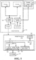
FIGURE 1 is a block diagram representing example components that may be used to compute a depth map at a higher resolution than camera resolution, according to one or more example implementations. -
FIG. 2 is a representation of an example of projecting moving dots into a scene, according to one or more example implementations. -
FIG. 3 is a representation of how projected dots may be captured in an example grid of image pixels, according to one or more example implementations. -
FIG. 4 is a representation of how dot intensity may be used to determine a projected dot's position and corresponding depth at a sub-pixel level, according to one or more example implementations. -
FIG. 5 is a representation of how a projected dot's position moves over time via moving a projector, for determining dot intensity at sub-pixel locations, according to one or more example implementations. -
FIG. 6 is a representation of how dot feature data or depth data captured at different times may be combined into merged data, according to one or more example implementations. -
FIG. 7 is a flow diagram representing example steps that may be taken to obtain a super-resolved depth map, according to one or more example implementations. -
FIG. 8 is a block diagram representing an exemplary non-limiting computing system or operating environment, in the form of a gaming system, into which one or more aspects of various embodiments described herein can be implemented. - Various aspects of the technology described herein are generally directed towards increasing the native resolution of a depth map by using a moving (e.g., slightly vibrating) pattern projector, such as moved by coupling the projector to a small piezoelectric motor. By tracking the path of features in the images over a series of frames and associating patterns across cameras (or from projector to camera), higher resolution depth information can be achieved.
- The technology may be used in the context of an active stereo system, such as where a pair of IR cameras are used in conjunction with an IR projector to provide texture for matching, and hence depth estimation. The technology may be based upon an accurate two-dimensional (2D) feature detector that is repeatable (e.g., including a peak detector for a dot pattern). By vibrating the pattern projector, the 2D features cover a number of sub-pixel positions, which are used for reconstructing an upsampled version of the native resolution of the system.
- It should be understood that any of the examples herein are non-limiting. As such, the present invention is not limited to any particular embodiments, aspects, concepts, structures, functionalities or examples described herein. Rather, any of the embodiments, aspects, concepts, structures, functionalities or examples described herein are non-limiting, and the present invention may be used various ways that provide benefits and advantages in active depth sensing and image processing in general.
-
FIG. 1 shows an example system in whichstereo cameras subsystem 104 capture images synchronized in time (e.g., the cameras are "genlocked"). In one implementation the cameras capture infrared (IR) images, as IR does not affect the visible appearance of the scene (which is valuable in video conferencing and object modeling applications, for example). As can be readily appreciated, in some scenarios such as studio environments, more than two IR depth-sensing cameras may be present. Further, one or more other cameras may be present in a given system, such as RBG cameras, and such other cameras may be used to help correlate dot pairs in different stereo images, for example. - In
FIG. 1 , aprojector 106 is shown that projects an IR pattern onto a scene, such as a pattern of spots (e.g., dots) or a line pattern, although other spot shapes and/or pattern types may be used. For purposes of brevity, dots are generally described hereinafter. By illuminating the scene with a relatively large number of distributed infrared dots, thecameras -
FIG. 2 exemplifies this projection concept. Theprojector 106, represented as a circle in between thestereo cameras scene 222. Thecameras scene 222 and (possibly) the background. In general, one or more features of the captured dots is indicative of the distance to the reflective surface. Note thatFIG. 2 is not intended to be to scale, nor convey any sizes, distance, dot distribution pattern, dot density and so on. - In one or more embodiments, the
projector 106 may be configured to project dots to a region that is slightly larger than thescene 222 that thecameras motion mechanism 114, such as a small motor that vibrates theprojector 106, causing the dot patterns move in a path over time. InFIG. 1 , theprojector 106 may be physically separate from the image capturing system or subsystem so that the vibration does not also jitter thecameras - In one alternative implementation, rather than shake the
projector 106 or a component part thereof (e.g., a diffractive optical element that diffracts infrared laser light into the dot pattern), theprojector 106 may project into a mirror system that is vibrated or otherwise moved. In this way, a mirror or the like, which may be much lighter and/or accessible and therefore more amenable to vibrating than a projector or a subcomponent thereof, may be used. Note that any such mirroring system that may be used, whether one mirror or more, is considered a component / part of the projector, even if only optically coupled to the projector and not physically coupled. Thus, as used herein, moving / vibrating the "projector" or "projector component" is the same as moving a mirror (or multiple mirrors) that reflectively project the light pattern. - Note that the placement of the
projector 106 may be outside the cameras (e.g.,FIG. 1 ), or in between the cameras (FIG. 2 ) or at another location, such as above or below one or both of the cameras. The examples herein are in no way limiting of where the cameras and/or projector are located relative to one another, and similarly, the cameras may be positioned at different positions relative to each other. - Returning to
FIG. 1 , in one implementation the example image capturing system orsubsystem 104 includes acontroller 108 that via acamera interface 110 controls the operation of thecameras projector interface 112 also controls the operation of theprojector 106 and/ormotion mechanism 114 that drives the projector movement (e.g., vibration). For example, thecameras projector 106 may be turned on or off, pulsed, and otherwise have one or more parameters controllably varied to provide different output patterns, for example. Themotion mechanism 114 may be turned on or off, or otherwise have one or more parameters controllably varied so as to change frequency, duty cycle, amplitude (e.g., to move dots in smaller or larger paths) and so on. - The images captured by the
cameras subsystem 118. In some implementations, theimage processing system 118 and image capturing system orsubsystem 104, or parts thereof, may be combined into a single device. For example a home entertainment device may include all of the components shown inFIG. 1 (as well as others not shown). In other implementations, parts (or all) of the image capturing system orsubsystem 104, such as the cameras and projector with motion mechanism, may be a separate device that couples to a gaming console, personal computer, mobile device, dedicated processing device and/or the like. Indeed, a gaming console is exemplified below as one environment that may be used for processing images into depth data. - The image processing system or
subsystem 118 includes aprocessor 120 and amemory 122 containing one or moreimage processing algorithms 124. Adense depth map 126 at the original camera resolution can be obtained through area-based matching, while asemi-dense depth map 128 can be extracted by matching features (such as dots and/or lines). - Described herein is an algorithm (
FIG. 6 ) or the like that leverages the moving projected pattern to provide a "super-resolved"depth map 130 comprising a depth map having higher-resolution than the native resolution of the cameras. Also shown inFIG. 1 is aninterface 132 to the image processing system orsubsystem 118, such as for connecting a keyboard, game controller, display, pointing device microphone for speech commands and/or the like as appropriate for a user to interact with an application or the like that uses the super-resolved depth map. - As is known, such as described in
U.S. published patent application no. 20130100256 , different dots or other projected elements have different features when captured, including intensity (brightness), depending on the distance from the projector to the reflective surfaces and/or the distance from the camera to the reflective surfaces. As is also known, the dots in different images taken at the same time (e.g., with genlocked stereo cameras) may be correlated with one another, such as by matching small (e.g., RGB) patches between RGB images of the same scene captured at the same instant. - Thus, with captured images, known algorithms can determine individual depth-related features (depth maps) for each image, and a disparity map that maintains differences between those images. The disparity map may be processed into a depth map based upon the disparity of certain features (e.g., intensity).
-
FIG. 3 shows a small (7×7)grid 330 of pixels, from a portion of some larger example image. As generally represented inFIG. 3 , the concentric circles represent captured dots projected on to a scene. To represent differing intensities for each dot, the smaller the circle, the greater the intensity. Thus, the center of the dot has the most intensity. InFIG. 3 , the block 332 (area-based stereo using intensity distribution) gives adense depth map 332, e.g., at each pixel in the native camera resolution). Further, note that inFIG. 3 the different diameters of the circles only suggest changes in intensity; the size of the circles and the grid squares are not intended to convey any particular scale, resolution, or the like, nor any particular intensity value or relative intensity values. Further, the density of the dots and/or their sizes or distribution are not intended to represent any actual density and/or distribution; however it is noted that the density, distribution and sizes of such dots are typically such that not every pixel is illuminated by a dot or even a portion of a dot. - As can be seen in
FIG. 3 , a feature for this dot pattern is the dot peak intensity location. This can be estimated to within sub-pixel accuracy. More particularly, as represented inFIG. 4 , the X-shaped crosses represent the estimated dot centers, with the pixels are divided into sub-pixels by the dashed lines, providing afiner grid 440. Each estimated center corresponds to a sub-pixel. The centers of some additional pixels outside the exemplified grid (e.g., the grid may be part of a larger image) are also shown, and will be described below with reference toFIG. 5 . - Note that
FIG. 4 subdivides the pixels into 2×2 sub-pixels to double the resolution. However instead of double sub-pixel resolution, even higher resolution may be obtained by subdividing the pixels further, e.g., into nine sub-pixels each, sixteen sub-pixels each and so on; (non-square subdivision may be used as well). - As shown in
FIG. 5 , (which represents agrid 550 corresponding to thegrid 440 ofFIG. 4 over a period of time), the dots, represented by the X-shaped crosses to show their center, may be moved by moving the projector, e.g., vibrating theprojector 106 via themotion mechanism 114 ofFIGS. 1 and2 . The dot / feature movement in this example is along the feature paths represented by the dotted lines. - Because of the movement over time, as captured in a sequence (set) of image frames, far more sub-pixels are illuminated (over the set of frames) by any given projected dot than without movement of that dot. Note that the paths in
FIG. 5 are not intended to convey any frame rate of capturing the dots, nor any frequency of vibrating the projector, but in general the movement and frame rate may be such that most if not all of the path is captured for each sub-pixel encountered. Further note that via the movement, the dots that were not within the exemplified grid initially but nearby may be projected into the grid at some point, while some of those in the grid leave it at some point (to illuminate other sub-pixels in the larger image, for example). - As mentioned above, it may be beneficial to intentionally project a dot pattern that is slightly larger than the scene (as exemplified in
FIG. 2 ). For example, consider that the grid represents a corner of a larger image or is along an edge of a larger image. If the projected dot pattern area is slightly larger than the scene, it can be seen that over time the movement illuminates some sub-pixels with dots that were previously outside the scene (and would continue to miss the scene if stationary). - In general, the movement is generally arbitrary / unpredictable for a given implementation. Notwithstanding, the amount of movement and vibration frequency may be controlled (or calibrated in a fixed system) relative to the frame rate of capturing the images and/or the dot density so that the benefits of the moving dots are obtained and made closer to optimal, e.g., the feature path traverses as many sub-pixels as possible and the frame rate is such that all or most of traversal is captured.
- As can be readily appreciated, the super-resolution of depth for a stationary scene (or one with slow movement relative to the camera frame rate and vibration frequency) can be determined by combining the depth / disparity maps computed from a set of images taken over time. While some depth data may still be missing (e.g., the
entire pixel 555 was not touched by a dot center, nor are other pixels and sub-pixels represented inFIG. 5 ), the amount of feature data captured for sub-pixels is significantly greater than without movement. Indeed, the benefit of dot movement can be seen even without dividing pixels to the sub-pixel level. - Combining the images to effectively increase dot density is represented in
FIG. 6 , where the features (or computed depth data) of two grids (frames) 662 and 664 may be combined (block 666) into amerged grid 668. Note that the feature descriptors of different image frames may be combined / merged, or the depth values first computed for the feature descriptors, with the depth values combined / merged. Further note that inFIG. 6 , the image frames are not necessarily consecutive (but may be); the dots may not have moved as much as depicted in two consecutive images depending on the speed of movement versus the camera frame rate. - In any event, it is seen that seven sub-pixels are in the feature path (or have depth data) as captured in the
example frame 662, and nine sub-pixels are in the feature path as captured in the other, e.g.,later frame 664; (some additional sub-pixels moved in from outside the grid 664). - Combining the
grids merged grid 668 having sixteen sub-pixels that were illuminated over time. As can be readily appreciated, the twoframes - For a given set of image frames over time, wherever the feature path passed through the higher resolution sub-pixel, the depth is directly computed for that sub-pixel. For each sub-pixel that is not in the path, depth information from the stereo capture at the original resolution and/or depth information from nearby super-resolved sub-pixel depth may be combined to estimate a depth for that sub-pixel. A straightforward way this may be accomplished is via push / pull interpolation, e.g., based on only the super-resolved depth information, which are well-known techniques in other areas of pixel processing. Note however that far less missing information needs to be estimated (e.g., interpolated).
- The above description is applicable to stationary scenes, (or scenes with slow depth changes relative to the frame rate and feature path). For a scene with moving objects, tracking may be performed to transfer information across different time frames, e.g., using known techniques such as deformable ICP (iterative closest point) solutions. Note that the projector and camera may be moved to change depth instead of or in addition to a scene, e.g., the image capturing system or subsystem may be attached to a robot, mounted to a camera dolly, and so forth.
-
FIG. 7 summarizes some of the concepts described herein using example steps in a flow diagram, beginning atstep 702 where the projector is controlled, which may be as simple as turning it on / removing it from an energy saving mode, or a more complex operation, such as adjusting dot pattern distribution, density, area of coverage, and/or adjusting motor vibration frequency, duty cycle, and/or amplitude, such as to adjust for a scenario / camera rate. - Step 704 captures the image or images. For brevity, stereo images are used hereafter in the description of
FIG. 7 . As the processing is likely faster than the frame rate, there may be a frame rate delay inherent instep 704; some processing or pre-processing may occur in parallel with the image capture. - Step 706 evaluates whether some criterion is met that triggers a super-resolution computation. For example, some number of frames (corresponding to an amount of time with a given frame rate) may trigger the super-resolution computation. In general, the feature path will be completed at some time and start repeating over the same sub-pixels, although not necessarily exactly; this completion time may be used to determine a trigger time. Alternatively, some amount of image processing may be done on existing images to determine whether a suitable coverage area in terms of the feature path hitting sub-pixels may be used, e.g., at a high enough percentage. If this alternative is used, time or number of frames may be used as a secondary trigger in case the path is such that it takes too long to reach sufficient coverage due to too much repetition.
- Further, such image pre-processing may be used to vary the projector or projector movement in some way. For example, if the pattern is not providing desired coverage, the pattern density may be increased (if not fixed), the vibration frequency, duty cycle and/or amplitude may be changed, and so forth. Note that the use of two or more motors (e.g., piezoelectric motors) may be used to change the shapes of vibration-induced feature paths as well, (as exemplified by Lissajous figures).
- Returning to step 706, if not triggered, a conventional depth map may be estimated and output via
step 710, e.g., at the native resolution based on the last images captured and processed. The process then returns to step 704 to capture the next set of images. Note that as described above, it is alternatively feasible to return to step 702 if a change to the projector / movement is possible and appropriate, such as because the feature paths are not attaining sufficient sub-pixel coverage. - If at
step 706 the super-resolution computation is triggered,step 712 combines the images to obtain feature data for as many sub-pixels as reached by the feature path. Part of the sub-pixel estimation and combination of images / depths may be ongoing as each new image set is captured rather than only when triggered (e.g., at least part ofstep 712 may be performed before step 706), wherebystep 712 may only needs to process and combine the latest image set / depth data to complete the super-resolved depth map. Note that in the event of a conflict where a sub-pixel has been reached more than once, (e.g., the sub-pixel 557 inFIG. 5 ), the most recent feature descriptor(s) may be used. Alternatively, other conflict resolution may be used, e.g., discarding what appears to be the noisier value, averaging, and so on may be used instead. - At
step 714, any missing sub-pixels are estimated, e.g., via interpolation. The super-high resolution depth map is output atstep 716, and the process repeated. - Note that while the examples herein are generally directed towards a stereo camera system, a single camera may similarly benefit from the technology described herein. Indeed, depth maps obtained via a single camera and projected light are well known; vibrating the projector likewise provides for more pixels or sub-pixels being illuminated, providing for more accurate native resolution depth maps or super-resolution depth maps. Time-of-flight depth sensing may also benefit from having more parts of an object being illuminated by vibrating the light source.
- It can be readily appreciated that the above-described implementation and its alternatives may be implemented on any suitable computing device, including a gaming system, personal computer, tablet, DVR, set-top box, smartphone and/or the like. Combinations of such devices are also feasible when multiple such devices are linked together. For purposes of description, a gaming (including media) system is described as one exemplary operating environment hereinafter.
-
FIG. 8 is a functional block diagram of an example gaming andmedia system 800 and shows functional components in more detail.Console 801 has a central processing unit (CPU) 802, and amemory controller 803 that facilitates processor access to various types of memory, including a flash Read Only Memory (ROM) 804, a Random Access Memory (RAM) 806, ahard disk drive 808, and portable media drive 809. In one implementation, theCPU 802 includes alevel 1cache 810, and alevel 2cache 812 to temporarily store data and hence reduce the number of memory access cycles made to the hard drive, thereby improving processing speed and throughput. - The
CPU 802, thememory controller 803, and various memory devices are interconnected via one or more buses (not shown). The details of the bus that is used in this implementation are not particularly relevant to understanding the subject matter of interest being discussed herein. However, it will be understood that such a bus may include one or more of serial and parallel buses, a memory bus, a peripheral bus, and a processor or local bus, using any of a variety of bus architectures. By way of example, such architectures can include an Industry Standard Architecture (ISA) bus, a Micro Channel Architecture (MCA) bus, an Enhanced ISA (EISA) bus, a Video Electronics Standards Association (VESA) local bus, and a Peripheral Component Interconnects (PCI) bus also known as a Mezzanine bus. - In one implementation, the
CPU 802, thememory controller 803, theROM 804, and theRAM 806 are integrated onto acommon module 814. In this implementation, theROM 804 is configured as a flash ROM that is connected to thememory controller 803 via a Peripheral Component Interconnect (PCI) bus or the like and a ROM bus or the like (neither of which are shown). TheRAM 806 may be configured as multiple Double Data Rate Synchronous Dynamic RAM (DDR SDRAM) modules that are independently controlled by thememory controller 803 via separate buses (not shown). Thehard disk drive 808 and the portable media drive 809 are shown connected to thememory controller 803 via the PCI bus and an AT Attachment (ATA)bus 816. However, in other implementations, dedicated data bus structures of different types can also be applied in the alternative. - A three-dimensional
graphics processing unit 820 and avideo encoder 822 form a video processing pipeline for high speed and high resolution (e.g., High Definition) graphics processing. Data are carried from thegraphics processing unit 820 to thevideo encoder 822 via a digital video bus (not shown). Anaudio processing unit 824 and an audio codec (coder/decoder) 826 form a corresponding audio processing pipeline for multi-channel audio processing of various digital audio formats. Audio data are carried between theaudio processing unit 824 and theaudio codec 826 via a communication link (not shown). The video and audio processing pipelines output data to an A/V (audio/video)port 828 for transmission to a television or other display / speakers. In the illustrated implementation, the video andaudio processing components module 814. -
FIG. 8 shows themodule 814 including aUSB host controller 830 and a network interface (NW I/F) 832, which may include wired and/or wireless components. TheUSB host controller 830 is shown in communication with theCPU 802 and thememory controller 803 via a bus (e.g., PCI bus) and serves as host for peripheral controllers 834. Thenetwork interface 832 provides access to a network (e.g., Internet, home network, etc.) and may be any of a wide variety of various wire or wireless interface components including an Ethernet card or interface module, a modem, a Bluetooth module, a cable modem, and the like. - In the example implementation depicted in
FIG. 8 , theconsole 801 includes acontroller support subassembly 840, for supporting four game controllers 841(1) - 841(4). Thecontroller support subassembly 840 includes any hardware and software components needed to support wired and/or wireless operation with an external control device, such as for example, a media and game controller. A front panel I/O subassembly 842 supports the multiple functionalities of apower button 843, aneject button 844, as well as any other buttons and any LEDs (light emitting diodes) or other indicators exposed on the outer surface of theconsole 801. Thesubassemblies module 814 via one ormore cable assemblies 846 or the like. In other implementations, theconsole 801 can include additional controller subassemblies. The illustrated implementation also shows an optical I/O interface 848 that is configured to send and receive signals (e.g., from a remote control 849) that can be communicated to themodule 814. - Memory units (MUs) 850(1) and 850(2) are illustrated as being connectable to MU ports "A" 852(1) and "B" 852(2), respectively. Each
MU 850 offers additional storage on which games, game parameters, and other data may be stored. In some implementations, the other data can include one or more of a digital game component, an executable gaming application, an instruction set for expanding a gaming application, and a media file. When inserted into theconsole 801, eachMU 850 can be accessed by thememory controller 803. - A system
power supply module 854 provides power to the components of thegaming system 800. Afan 856 cools the circuitry within theconsole 801. - An
application 860 comprising machine instructions is typically stored on thehard disk drive 808. When theconsole 801 is powered on, various portions of theapplication 860 are loaded into theRAM 806, and/or thecaches CPU 802. In general, theapplication 860 can include one or more program modules for performing various display functions, such as controlling dialog screens for presentation on a display (e.g., high definition monitor), controlling transactions based on user inputs and controlling data transmission and reception between theconsole 801 and externally connected devices. - The
gaming system 800 may be operated as a standalone system by connecting the system to high definition monitor, a television, a video projector, or other display device. In this standalone mode, thegaming system 800 enables one or more players to play games, or enjoy digital media, e.g., by watching movies, or listening to music. However, with the integration of broadband connectivity made available through thenetwork interface 832,gaming system 800 may further be operated as a participating component in a larger network gaming community or system. - While the invention is susceptible to various modifications and alternative constructions, certain illustrated embodiments thereof are shown in the drawings and have been described above in detail. It should be understood, however, that there is no intention to limit the invention to the specific forms disclosed, but on the contrary, the intention is to cover all modifications, alternative constructions, and equivalents falling within the spirit and scope of the invention.
- Aspects of the invention are disclosed in the following numbered clauses:
- 1. A method, comprising, computing a depth map having a higher resolution than a resolution of each sensor of a sensor set comprising one or more sensors, including projecting a moving pattern of light into a scene, capturing a plurality of images at different times via the sensor set, processing at least some of the images to obtain computed depth data for sub-pixels based upon which sub-pixel locations were in a path corresponding to the moving pattern of light, estimating depth data for any sub-pixels for which computed depth data is not obtained, and outputting a depth map comprising depth data for each sub-pixel.
- 2. The method of clause1 wherein projecting the moving pattern of light comprises a) projecting spots into the scene, or b) projecting at least one of a line pattern, color codes, corners, or other distinct shapes into the scene, or c) vibrating or otherwise moving a projector or projector component, or any combination of a), b) or c).
- 3. The method of clause1 further comprising, varying vibration or other movement parameters.
- 4. The method ofclause1 wherein estimating the depth data comprises interpolating sub-pixel data based at least in part upon other sub-pixel depth values or feature values, or interpolating sub-pixel data based at least in part upon other sub-pixel depth values or feature values corresponding to a native or lower resolution map, or both
- 5. The method of clause1 further comprising, projecting part of the moving pattern outside the scene to provide for movement into the scene resulting from projection movement
- 6. A system comprising, a projector configured to project a light pattern towards a scene, a sensor set comprising at least one sensor configured to sense light from the light pattern that is reflected from the scene, a motion mechanism coupled to the projector to move the light pattern over time, and an image processing subsystem configured to process a plurality of images captured over time in which the light pattern has moved within the plurality of images to compute a depth map.
- 7. The system ofclause6 wherein the image processing subsystem is configured to compute the depth map at a sub-pixel resolution that is higher than a native resolution of the sensor set.
- 8. A method comprising, moving a projector or projector component to project a light pattern into a scene, the moving causing the light pattern to move over time relative to the scene, and using images of the scene captured at different times for depth sensing.
- 9. The method ofclause8 further comprising, computing a depth map based upon the depth sensing, including combining sub-pixel level data corresponding to the images to compute a sub-pixel level depth map.
- 10. The method ofclause9 further comprising, estimating part of the sub-pixel level data for data that is not directly obtainable from the images.
Claims (15)
- A method for computing a depth map having a higher resolution than a resolution of each sensor of a sensor set, the method comprising;
vibrating a projector;
projecting, while the projector is vibrating, a pattern of light comprising a plurality of dots into a scene, the pattern of light moving based on the vibrating;
capturing a plurality of images at different times via the sensor set while the projector is vibrating, the sensor set comprising at least two synchronized sensors, wherein a frequency of the vibrating is relative to a frame rate of capturing the plurality of images;
processing at least some of the images to obtain computed depth data; and
outputting a depth map comprising the depth data. - The method of claim 1, wherein the sensor set comprises a plurality of stereo cameras, and wherein processing at least some of the images to obtain the computed depth data comprises using disparity data indicative of differences between stereo images.
- The method of claim 1 or claim 2, wherein projecting the moving pattern of light comprises projecting the plurality of dots into the scene the dots of the pattern of light are projected to a region that is larger than the scene.
- The method of any preceding claim, wherein projecting the moving pattern of light further comprises projecting at least one of a line pattern, color codes, corners, or other distinct shapes into the scene.
- The method of any preceding claim, wherein a frequency of the vibrating is relative to a frame rate of capturing the plurality of images and a density of the plurality of dots.
- The method of any preceding claim 1, wherein the processing comprises processing at least some of the images to obtain computed depth data for sub-pixels based upon which sub-pixel locations were in a path corresponding to the moving pattern of light.
- The method of any preceding claim, further comprising projecting part of the moving pattern outside the scene to provide for movement into the scene resulting from the vibrating.
- A system comprising:a projector configured to vibrate and project a light pattern comprising a plurality of dots towards a scene while the projector is vibrating;a sensor set comprising at least two synchronized sensors configured to sense light from the light pattern that is reflected from the scene while the projector is vibrating;
a motion device coupled to the projector to move the light pattern over time while the projector is vibrating; andan image processor for processing a plurality of images captured over time while the projector is vibrating in which the light pattern has moved within the plurality of images to compute a depth map, wherein a frequency of the vibrating is relative to a frame rate of capturing the plurality of images. - The system of claim 8, wherein the image processor is configured to compute the depth map at a sub-pixel resolution that is higher than a native resolution of the sensor set.
- The system of claim 8 or claim 9, wherein the motion device comprises at least one motor.
- The system of any one of claims 8 to 10, wherein the sensor set and the projector are incorporated into a single device.
- The system of any one of claims 8 to 11, wherein a frequency of the vibrating is relative to a frame rate of capturing the plurality of images and a density of the plurality of dots.
- One or more computer-readable storage media comprising computer-executable instruction for computing a depth map having a higher resolution than a resolution of each sensor of a sensor set, the computer-executable instruction causing one or more processors to perform operations comprising:vibrating a pattern of light projected from a projector, the pattern of light comprising a plurality of dots into a scene, the pattern of light moving based on the vibrating;capturing a plurality of images at different times via the sensor set while the pattern of light is vibrating, the sensor set comprising at least two synchronized sensors, wherein a frequency of the vibrating is relative to a frame rate of capturing the plurality of images;processing at least some of the images to obtain computed depth data; and
outputting a depth map comprising the depth data. - The one or more computer-readable storage media of claim 13, wherein the sensor set comprises a plurality of stereo cameras, and wherein processing at least some of the images to obtain the computed depth data comprises using disparity data indicative of differences between stereo images.
- The one or more computer-readable storage media of claim 13 or claim 14, wherein vibrating the light pattern comprises projecting the light pattern into a mirror that is vibrated.
Applications Claiming Priority (4)
| Application Number | Priority Date | Filing Date | Title |
|---|---|---|---|
| US201361812232P | 2013-04-15 | 2013-04-15 | |
| US13/924,485 US9922249B2 (en) | 2013-04-15 | 2013-06-21 | Super-resolving depth map by moving pattern projector |
| PCT/US2014/033911 WO2014172223A1 (en) | 2013-04-15 | 2014-04-14 | Super-resolving depth map by moving pattern projector |
| EP14727992.1A EP2986936B1 (en) | 2013-04-15 | 2014-04-14 | Super-resolving depth map by moving pattern projector |
Related Parent Applications (2)
| Application Number | Title | Priority Date | Filing Date |
|---|---|---|---|
| EP14727992.1A Division EP2986936B1 (en) | 2013-04-15 | 2014-04-14 | Super-resolving depth map by moving pattern projector |
| EP14727992.1A Division-Into EP2986936B1 (en) | 2013-04-15 | 2014-04-14 | Super-resolving depth map by moving pattern projector |
Publications (2)
| Publication Number | Publication Date |
|---|---|
| EP3757510A1 true EP3757510A1 (en) | 2020-12-30 |
| EP3757510B1 EP3757510B1 (en) | 2022-06-29 |
Family
ID=51686521
Family Applications (9)
| Application Number | Title | Priority Date | Filing Date |
|---|---|---|---|
| EP14727992.1A Not-in-force EP2986936B1 (en) | 2013-04-15 | 2014-04-14 | Super-resolving depth map by moving pattern projector |
| EP14725861.0A Ceased EP2986931A1 (en) | 2013-04-15 | 2014-04-14 | Robust stereo depth system |
| EP14725312.4A Active EP2986935B1 (en) | 2013-04-15 | 2014-04-14 | Intensity-modulated light pattern for active stereo |
| EP14726261.2A Not-in-force EP2987320B1 (en) | 2013-04-15 | 2014-04-14 | Extracting true color from a color and infrared sensor |
| EP14724600.3A Active EP2987132B1 (en) | 2013-04-15 | 2014-04-14 | Diffractive optical element with undiffracted light expansion for eye safe operation |
| EP20184935.3A Active EP3757510B1 (en) | 2013-04-15 | 2014-04-14 | Depth map by vibrating pattern projector |
| EP14724942.9A Active EP2987138B1 (en) | 2013-04-15 | 2014-04-14 | Active stereo with adaptive support weights from a separate image |
| EP14723271.4A Ceased EP2987131A1 (en) | 2013-04-15 | 2014-04-14 | Parallel memories for multidimensional data access |
| EP14724934.6A Not-in-force EP2987323B1 (en) | 2013-04-15 | 2014-04-14 | Active stereo with satellite device or devices |
Family Applications Before (5)
| Application Number | Title | Priority Date | Filing Date |
|---|---|---|---|
| EP14727992.1A Not-in-force EP2986936B1 (en) | 2013-04-15 | 2014-04-14 | Super-resolving depth map by moving pattern projector |
| EP14725861.0A Ceased EP2986931A1 (en) | 2013-04-15 | 2014-04-14 | Robust stereo depth system |
| EP14725312.4A Active EP2986935B1 (en) | 2013-04-15 | 2014-04-14 | Intensity-modulated light pattern for active stereo |
| EP14726261.2A Not-in-force EP2987320B1 (en) | 2013-04-15 | 2014-04-14 | Extracting true color from a color and infrared sensor |
| EP14724600.3A Active EP2987132B1 (en) | 2013-04-15 | 2014-04-14 | Diffractive optical element with undiffracted light expansion for eye safe operation |
Family Applications After (3)
| Application Number | Title | Priority Date | Filing Date |
|---|---|---|---|
| EP14724942.9A Active EP2987138B1 (en) | 2013-04-15 | 2014-04-14 | Active stereo with adaptive support weights from a separate image |
| EP14723271.4A Ceased EP2987131A1 (en) | 2013-04-15 | 2014-04-14 | Parallel memories for multidimensional data access |
| EP14724934.6A Not-in-force EP2987323B1 (en) | 2013-04-15 | 2014-04-14 | Active stereo with satellite device or devices |
Country Status (11)
| Country | Link |
|---|---|
| US (14) | US10268885B2 (en) |
| EP (9) | EP2986936B1 (en) |
| JP (1) | JP6469080B2 (en) |
| KR (2) | KR102207768B1 (en) |
| CN (8) | CN105308650B (en) |
| AU (1) | AU2014254219B2 (en) |
| BR (1) | BR112015025819A8 (en) |
| CA (1) | CA2907895C (en) |
| MX (1) | MX357307B (en) |
| RU (1) | RU2663329C2 (en) |
| WO (8) | WO2014172227A1 (en) |
Families Citing this family (206)
| Publication number | Priority date | Publication date | Assignee | Title |
|---|---|---|---|---|
| KR20120072245A (en) * | 2010-12-23 | 2012-07-03 | 한국전자통신연구원 | Apparatus and method for stereo matching |
| EP2826237A4 (en) * | 2012-03-13 | 2015-08-19 | Dolby Lab Licensing Corp | LIGHTING SYSTEM AND METHOD FOR ENHANCING IMAGE AND OBJECT |
| EP2700920B1 (en) | 2012-08-23 | 2016-06-22 | ams AG | Light sensor system and method for processing light sensor signals |
| US10268885B2 (en) | 2013-04-15 | 2019-04-23 | Microsoft Technology Licensing, Llc | Extracting true color from a color and infrared sensor |
| US9467680B2 (en) | 2013-12-12 | 2016-10-11 | Intel Corporation | Calibration of a three-dimensional acquisition system |
| EP3088839B1 (en) * | 2013-12-27 | 2018-12-26 | Sony Corporation | Image processing device and image processing method |
| US9720506B2 (en) * | 2014-01-14 | 2017-08-01 | Microsoft Technology Licensing, Llc | 3D silhouette sensing system |
| CN105939837B (en) * | 2014-01-16 | 2019-05-10 | 惠普发展公司,有限责任合伙企业 | Processing slice data for additive manufacturing systems |
| US11265534B2 (en) * | 2014-02-08 | 2022-03-01 | Microsoft Technology Licensing, Llc | Environment-dependent active illumination for stereo matching |
| US9842424B2 (en) * | 2014-02-10 | 2017-12-12 | Pixar | Volume rendering using adaptive buckets |
| US20170078649A1 (en) | 2014-03-07 | 2017-03-16 | Brown University | Method and system for unsynchronized structured lighting |
| US10005126B2 (en) * | 2014-03-19 | 2018-06-26 | Autodesk, Inc. | Systems and methods for improved 3D printing |
| US9674493B2 (en) * | 2014-03-24 | 2017-06-06 | Omnivision Technologies, Inc. | Color image sensor with metal mesh to detect infrared light |
| US10349037B2 (en) * | 2014-04-03 | 2019-07-09 | Ams Sensors Singapore Pte. Ltd. | Structured-stereo imaging assembly including separate imagers for different wavelengths |
| GB201407270D0 (en) * | 2014-04-24 | 2014-06-11 | Cathx Res Ltd | 3D data in underwater surveys |
| US9823842B2 (en) | 2014-05-12 | 2017-11-21 | The Research Foundation For The State University Of New York | Gang migration of virtual machines using cluster-wide deduplication |
| US9533449B2 (en) | 2014-06-19 | 2017-01-03 | Autodesk, Inc. | Material deposition systems with four or more axes |
| US10252466B2 (en) | 2014-07-28 | 2019-04-09 | Massachusetts Institute Of Technology | Systems and methods of machine vision assisted additive fabrication |
| CN106461378B (en) * | 2014-08-08 | 2019-10-25 | 塞姆布有限公司 | Vehicle equipment with scanning system for contactless measurement |
| US10455212B1 (en) * | 2014-08-25 | 2019-10-22 | X Development Llc | Projected pattern motion/vibration for depth sensing |
| JP6397698B2 (en) * | 2014-08-28 | 2018-09-26 | 任天堂株式会社 | Information processing terminal, information processing program, information processing terminal system, and information processing method |
| US9507995B2 (en) * | 2014-08-29 | 2016-11-29 | X Development Llc | Combination of stereo and structured-light processing |
| DE102014113389A1 (en) * | 2014-09-17 | 2016-03-17 | Pilz Gmbh & Co. Kg | Method and device for identifying structural elements of a projected structural pattern in camera images |
| EP3197667B1 (en) | 2014-09-26 | 2021-06-02 | Hewlett-Packard Development Company, L.P. | Processssor readable medium and method for additive manufacturing |
| EP3018587B1 (en) * | 2014-11-05 | 2018-08-29 | Renesas Electronics Europe GmbH | Memory access unit |
| JP6302399B2 (en) * | 2014-11-17 | 2018-03-28 | キヤノン株式会社 | Image forming apparatus provided with short-range wireless communication unit, control method thereof, and program |
| EP3043159B1 (en) * | 2015-01-08 | 2019-12-18 | ams AG | Method for processing light sensor signals and light sensor system |
| JPWO2016098400A1 (en) * | 2014-12-15 | 2017-09-21 | ソニー株式会社 | Imaging device assembly, three-dimensional shape measuring device, and motion detecting device |
| EP3040941B1 (en) * | 2014-12-29 | 2017-08-02 | Dassault Systèmes | Method for calibrating a depth camera |
| US11562286B2 (en) * | 2015-02-06 | 2023-01-24 | Box, Inc. | Method and system for implementing machine learning analysis of documents for classifying documents by associating label values to the documents |
| DE102015202182A1 (en) * | 2015-02-06 | 2016-08-11 | Siemens Aktiengesellschaft | Apparatus and method for sequential, diffractive pattern projection |
| US9699394B2 (en) | 2015-03-09 | 2017-07-04 | Microsoft Technology Licensing, Llc | Filter arrangement for image sensor |
| JP6484071B2 (en) * | 2015-03-10 | 2019-03-13 | アルプスアルパイン株式会社 | Object detection device |
| CN106032059B (en) * | 2015-03-13 | 2019-11-26 | 三纬国际立体列印科技股份有限公司 | Three-dimensional printing method and three-dimensional printing device |
| KR102238794B1 (en) * | 2015-03-25 | 2021-04-09 | 한국전자통신연구원 | Method for increasing film speed of video camera |
| DE112015006245B4 (en) | 2015-03-30 | 2019-05-23 | Fujifilm Corporation | Distance image detection device and distance image detection method |
| EP3081384B1 (en) * | 2015-04-17 | 2019-11-13 | Canon Kabushiki Kaisha | Image processing apparatus, image processing method, and program |
| KR20250035038A (en) | 2015-04-19 | 2025-03-11 | 포토내이션 리미티드 | Multi-baseline camera array system architectures for depth augmentation in vr/ar applications |
| US9751263B2 (en) * | 2015-04-20 | 2017-09-05 | Xerox Corporation | Injection molding to finish parts printed with a three-dimensional object printer |
| EP3298432B1 (en) * | 2015-05-18 | 2019-07-10 | Lasermotive, Inc. | Multi-layered safety system |
| US9683834B2 (en) * | 2015-05-27 | 2017-06-20 | Intel Corporation | Adaptable depth sensing system |
| US9495584B1 (en) * | 2015-06-05 | 2016-11-15 | Digital Signal Corporation | System and method for facial recognition using images captured from a target illuminated with infrared light |
| US11054664B2 (en) * | 2015-06-18 | 2021-07-06 | Apple Inc. | Monitoring DOE performance using software scene evaluation |
| US9734409B2 (en) * | 2015-06-24 | 2017-08-15 | Netflix, Inc. | Determining native resolutions of video sequences |
| WO2017009324A1 (en) * | 2015-07-13 | 2017-01-19 | Koninklijke Philips N.V. | Method and apparatus for determining a depth map for an image |
| WO2017014691A1 (en) * | 2015-07-17 | 2017-01-26 | Heptagon Micro Optics Pte. Ltd. | Generating a distance map based on captured images of a scene |
| US10699476B2 (en) | 2015-08-06 | 2020-06-30 | Ams Sensors Singapore Pte. Ltd. | Generating a merged, fused three-dimensional point cloud based on captured images of a scene |
| WO2017030507A1 (en) | 2015-08-19 | 2017-02-23 | Heptagon Micro Optics Pte. Ltd. | Generating a disparity map having reduced over-smoothing |
| CN106550228B (en) * | 2015-09-16 | 2019-10-15 | 上海图檬信息科技有限公司 | The equipment for obtaining the depth map of three-dimensional scenic |
| US20170116779A1 (en) * | 2015-10-26 | 2017-04-27 | Microsoft Technology Licensing, Llc | Volumetric representation of objects |
| US10554956B2 (en) | 2015-10-29 | 2020-02-04 | Dell Products, Lp | Depth masks for image segmentation for depth-based computational photography |
| US10021371B2 (en) | 2015-11-24 | 2018-07-10 | Dell Products, Lp | Method and apparatus for gross-level user and input detection using similar or dissimilar camera pair |
| KR102323217B1 (en) * | 2015-12-21 | 2021-11-08 | 삼성전자주식회사 | Depth sensor, 3 Dimensional Camera and Method for controlling noise of macro pixel |
| US9800795B2 (en) * | 2015-12-21 | 2017-10-24 | Intel Corporation | Auto range control for active illumination depth camera |
| US10761497B2 (en) | 2016-01-14 | 2020-09-01 | Microsoft Technology Licensing, Llc | Printing 3D objects with automatic dimensional accuracy compensation |
| CN106980630B (en) * | 2016-01-19 | 2020-03-10 | 菜鸟智能物流控股有限公司 | Data rotation display method and device |
| KR20180101496A (en) * | 2016-02-18 | 2018-09-12 | 애플 인크. | Head-mounted display for virtual and mixed reality with inside-out location, user body and environment tracking |
| WO2017149932A1 (en) * | 2016-03-03 | 2017-09-08 | ソニー株式会社 | Medical image processing device, system, method, and program |
| DE102016106121B4 (en) | 2016-04-04 | 2025-12-31 | Carl Zeiss Ag | Method and device for determining parameters for spectacle fitting |
| WO2017193013A1 (en) * | 2016-05-06 | 2017-11-09 | Zhang, Yunbo | Determining manufacturable models |
| JP6153050B1 (en) * | 2016-06-08 | 2017-06-28 | パナソニックIpマネジメント株式会社 | Projection system |
| US10659764B2 (en) * | 2016-06-20 | 2020-05-19 | Intel Corporation | Depth image provision apparatus and method |
| US10609359B2 (en) | 2016-06-22 | 2020-03-31 | Intel Corporation | Depth image provision apparatus and method |
| US10638060B2 (en) * | 2016-06-28 | 2020-04-28 | Intel Corporation | Color correction of RGBIR sensor stream based on resolution recovery of RGB and IR channels |
| CN106210568A (en) * | 2016-07-15 | 2016-12-07 | 深圳奥比中光科技有限公司 | Image processing method and device |
| US10241244B2 (en) | 2016-07-29 | 2019-03-26 | Lumentum Operations Llc | Thin film total internal reflection diffraction grating for single polarization or dual polarization |
| CN106204414A (en) * | 2016-08-05 | 2016-12-07 | 蓝普金睛(北京)科技有限公司 | A kind of method and system of dynamic image caching |
| US10192311B2 (en) * | 2016-08-05 | 2019-01-29 | Qualcomm Incorporated | Methods and apparatus for codeword boundary detection for generating depth maps |
| CN106375740B (en) * | 2016-09-28 | 2018-02-06 | 华为技术有限公司 | Generate the methods, devices and systems of RGB image |
| CN106447588A (en) * | 2016-09-30 | 2017-02-22 | 天津大学 | Fresnel transform domain chaotic double random phase encoding optical image encryption method |
| JP6645394B2 (en) * | 2016-10-03 | 2020-02-14 | 株式会社デンソー | Image sensor |
| US10456984B2 (en) | 2016-12-16 | 2019-10-29 | Massachusetts Institute Of Technology | Adaptive material deposition for additive manufacturing |
| EP3565259A1 (en) * | 2016-12-28 | 2019-11-06 | Panasonic Intellectual Property Corporation of America | Three-dimensional model distribution method, three-dimensional model receiving method, three-dimensional model distribution device, and three-dimensional model receiving device |
| US10372974B2 (en) | 2017-01-11 | 2019-08-06 | Microsoft Technology Licensing, Llc | 3D imaging recognition by stereo matching of RGB and infrared images |
| CN108399633A (en) * | 2017-02-06 | 2018-08-14 | 罗伯团队家居有限公司 | Method and apparatus for stereoscopic vision |
| CN106908391A (en) * | 2017-02-10 | 2017-06-30 | 广东欧珀移动通信有限公司 | Terminal cover plate glass colour recognition methods and device |
| CN106909320B (en) * | 2017-02-20 | 2020-01-21 | 北京中科睿芯科技有限公司 | Method, device and system for expanding and transmitting multidimensional data |
| WO2018154965A1 (en) * | 2017-02-24 | 2018-08-30 | ソニー株式会社 | Image processing device and imaging apparatus |
| US10955814B2 (en) | 2017-04-24 | 2021-03-23 | Autodesk, Inc. | Closed-loop robotic deposition of material |
| US11181886B2 (en) * | 2017-04-24 | 2021-11-23 | Autodesk, Inc. | Closed-loop robotic deposition of material |
| CN107084686B (en) * | 2017-04-26 | 2019-04-30 | 西安交通大学 | A dynamic multi-knife scanning measurement method without moving parts |
| US11300402B2 (en) * | 2017-05-31 | 2022-04-12 | Hewlett-Packard Development Company, L.P. | Deriving topology information of a scene |
| US20180347967A1 (en) * | 2017-06-01 | 2018-12-06 | RGBDsense Information Technology Ltd. | Method and apparatus for generating a random coding pattern for coding structured light |
| US10817493B2 (en) | 2017-07-07 | 2020-10-27 | Raytheon Company | Data interpolation |
| KR102346031B1 (en) | 2017-07-25 | 2022-01-03 | 삼성디스플레이 주식회사 | Display device and method for driving the same |
| KR102402477B1 (en) * | 2017-08-04 | 2022-05-27 | 엘지이노텍 주식회사 | Time of flight module |
| US10586342B2 (en) * | 2017-08-31 | 2020-03-10 | Facebook Technologies, Llc | Shifting diffractive optical element for adjustable depth sensing resolution |
| US10962790B2 (en) | 2017-09-05 | 2021-03-30 | Facebook Technologies, Llc | Depth measurement using a pulsed structured light projector |
| US20190072771A1 (en) * | 2017-09-05 | 2019-03-07 | Facebook Technologies, Llc | Depth measurement using multiple pulsed structured light projectors |
| DE102017215850B4 (en) * | 2017-09-08 | 2019-12-24 | Robert Bosch Gmbh | Process for producing a diffractive optical element, LIDAR system with a diffractive optical element and motor vehicle with a LIDAR system |
| CN107884066A (en) * | 2017-09-29 | 2018-04-06 | 深圳奥比中光科技有限公司 | Optical sensor and its 3D imaging devices based on flood lighting function |
| US10545457B2 (en) | 2017-12-05 | 2020-01-28 | K Laser Technology, Inc. | Optical projector with off-axis diffractive element and conjugate images |
| US10310281B1 (en) * | 2017-12-05 | 2019-06-04 | K Laser Technology, Inc. | Optical projector with off-axis diffractive element |
| CN109889799B (en) * | 2017-12-06 | 2020-08-25 | 西安交通大学 | Monocular structure light depth perception method and device based on RGBIR camera |
| US10628952B2 (en) | 2017-12-11 | 2020-04-21 | Google Llc | Dual-band stereo depth sensing system |
| DE102017222708A1 (en) * | 2017-12-14 | 2019-06-19 | Conti Temic Microelectronic Gmbh | 3D environment detection via projector and camera modules |
| US11227371B2 (en) * | 2017-12-14 | 2022-01-18 | Nec Corporation | Image processing device, image processing method, and image processing program |
| JP6939501B2 (en) * | 2017-12-15 | 2021-09-22 | オムロン株式会社 | Image processing system, image processing program, and image processing method |
| CN108133494A (en) * | 2018-01-17 | 2018-06-08 | 南京华捷艾米软件科技有限公司 | The system and method for generating depth map and cromogram simultaneously using RGB-IR |
| DE102019000272B4 (en) | 2018-01-19 | 2023-11-16 | Cognex Corporation | SYSTEM FOR FORMING A HOMOGENIZED ILLUMINATION LINE WHICH CAN BE IMAGED AS A LOW SPECKLE LINE |
| US10317684B1 (en) | 2018-01-24 | 2019-06-11 | K Laser Technology, Inc. | Optical projector with on axis hologram and multiple beam splitter |
| CN108319437B (en) * | 2018-02-28 | 2019-01-11 | 上海熙香艺享电子商务有限公司 | Content big data concentration analysis platform |
| CN108490632B (en) * | 2018-03-12 | 2020-01-10 | Oppo广东移动通信有限公司 | Laser projection module, depth camera and electronic device |
| JP2021518535A (en) * | 2018-03-20 | 2021-08-02 | マジック アイ インコーポレイテッド | Distance measurement using projection patterns of various densities |
| US10643341B2 (en) | 2018-03-22 | 2020-05-05 | Microsoft Technology Licensing, Llc | Replicated dot maps for simplified depth computation using machine learning |
| US10565720B2 (en) | 2018-03-27 | 2020-02-18 | Microsoft Technology Licensing, Llc | External IR illuminator enabling improved head tracking and surface reconstruction for virtual reality |
| US10771766B2 (en) * | 2018-03-30 | 2020-09-08 | Mediatek Inc. | Method and apparatus for active stereo vision |
| CN108564613A (en) * | 2018-04-12 | 2018-09-21 | 维沃移动通信有限公司 | A kind of depth data acquisition methods and mobile terminal |
| US10520923B2 (en) | 2018-05-22 | 2019-12-31 | Mantle Inc. | Method and system for automated toolpath generation |
| US10878590B2 (en) * | 2018-05-25 | 2020-12-29 | Microsoft Technology Licensing, Llc | Fusing disparity proposals in stereo matching |
| CN108917640A (en) * | 2018-06-06 | 2018-11-30 | 佛山科学技术学院 | A kind of laser blind hole depth detection method and its system |
| FI128523B (en) | 2018-06-07 | 2020-07-15 | Ladimo Oy | Modeling the topography of a three-dimensional surface |
| ES3037621T3 (en) | 2018-07-19 | 2025-10-03 | Activ Surgical Inc | Systems and methods for multi-modal sensing of depth in vision systems for automated surgical robots |
| US11067820B2 (en) * | 2018-07-31 | 2021-07-20 | Himax Technologies Limited | Structured light projector and three-dimensional image sensing module |
| CN109102540B (en) * | 2018-08-16 | 2022-01-28 | 杭州电子科技大学 | FPGA-based lower limit separation and lane division method for marked area blocks |
| TWI676781B (en) * | 2018-08-17 | 2019-11-11 | 鑑微科技股份有限公司 | Three-dimensional scanning system |
| US10761337B2 (en) * | 2018-08-24 | 2020-09-01 | Himax Technologies Limited | Projecting apparatus for spreading non-diffracted light |
| JP6907277B2 (en) * | 2018-08-30 | 2021-07-21 | コグネックス・コーポレイション | Methods and devices for generating 3D reconstructions of distorted objects |
| US11039122B2 (en) * | 2018-09-04 | 2021-06-15 | Google Llc | Dark flash photography with a stereo camera |
| CN109146953B (en) * | 2018-09-11 | 2021-12-10 | 杭州电子科技大学 | FPGA-based upper limit separation and lane separation method for marked area blocks |
| US10791277B2 (en) * | 2018-09-11 | 2020-09-29 | Cognex Corporation | Methods and apparatus for optimizing image acquisition of objects subject to illumination patterns |
| US20200082160A1 (en) * | 2018-09-12 | 2020-03-12 | Kneron (Taiwan) Co., Ltd. | Face recognition module with artificial intelligence models |
| KR102562360B1 (en) * | 2018-10-05 | 2023-08-02 | 엘지이노텍 주식회사 | Method and camera module for acquiring depth information |
| CN109532021B (en) * | 2018-10-10 | 2020-08-25 | 浙江大学 | Layer-by-layer detection method of 3D printing deposition defects based on structural light linear anomalies |
| US11176694B2 (en) * | 2018-10-19 | 2021-11-16 | Samsung Electronics Co., Ltd | Method and apparatus for active depth sensing and calibration method thereof |
| US11480793B2 (en) * | 2018-10-24 | 2022-10-25 | Google Llc | Systems, devices, and methods for aligning a lens in a laser projector |
| JP7146576B2 (en) * | 2018-10-29 | 2022-10-04 | 芝浦機械株式会社 | Layered manufacturing apparatus, layered manufacturing method, and program |
| US11460931B2 (en) | 2018-10-31 | 2022-10-04 | Hewlett-Packard Development Company, L.P. | Recovering perspective distortions |
| US11024037B2 (en) | 2018-11-15 | 2021-06-01 | Samsung Electronics Co., Ltd. | Foreground-background-aware atrous multiscale network for disparity estimation |
| US10628968B1 (en) * | 2018-12-05 | 2020-04-21 | Toyota Research Institute, Inc. | Systems and methods of calibrating a depth-IR image offset |
| CN112912896B (en) * | 2018-12-14 | 2024-06-28 | 苹果公司 | Machine learning assisted image prediction |
| CN109798838B (en) * | 2018-12-19 | 2020-10-27 | 西安交通大学 | A ToF depth sensor based on laser speckle projection and its ranging method |
| CN109741386B (en) * | 2018-12-26 | 2020-07-31 | 豪威科技(武汉)有限公司 | Enhancement method of stereoscopic vision system and stereoscopic vision system |
| US10917568B2 (en) * | 2018-12-28 | 2021-02-09 | Microsoft Technology Licensing, Llc | Low-power surface reconstruction |
| CN113853151A (en) | 2018-12-28 | 2021-12-28 | 艾科缇弗外科公司 | User interface element for orienting a remote camera during surgery |
| CN113993474A (en) | 2018-12-28 | 2022-01-28 | 艾科缇弗外科公司 | System and method for optimizing accessibility, workspace and dexterity in minimally invasive surgery |
| US11333895B1 (en) | 2019-01-11 | 2022-05-17 | Facebook Technologies, Llc | Systems and methods for structured light projector operational safety |
| JP7211835B2 (en) * | 2019-02-04 | 2023-01-24 | i-PRO株式会社 | IMAGING SYSTEM AND SYNCHRONIZATION CONTROL METHOD |
| CN110087057B (en) * | 2019-03-11 | 2021-10-12 | 歌尔股份有限公司 | Depth image acquisition method and device for projector |
| US20200292297A1 (en) * | 2019-03-15 | 2020-09-17 | Faro Technologies, Inc. | Three-dimensional measurement device |
| CN113950279B (en) | 2019-04-08 | 2023-04-14 | 艾科缇弗外科公司 | Systems and methods for medical imaging |
| US12292564B2 (en) | 2019-04-08 | 2025-05-06 | Activ Surgical, Inc. | Systems and methods for medical imaging |
| US11039118B2 (en) | 2019-04-17 | 2021-06-15 | XRSpace CO., LTD. | Interactive image processing system using infrared cameras |
| WO2020214821A1 (en) | 2019-04-19 | 2020-10-22 | Activ Surgical, Inc. | Systems and methods for trocar kinematics |
| EP3731175A1 (en) * | 2019-04-26 | 2020-10-28 | XRSpace CO., LTD. | Interactive image processing system using infrared cameras |
| CN110111390A (en) * | 2019-05-15 | 2019-08-09 | 湖南科技大学 | Thin-wall part omnidirectional vibration measurement method and system based on binocular vision optical flow tracking |
| CN110012206A (en) * | 2019-05-24 | 2019-07-12 | Oppo广东移动通信有限公司 | Image acquisition method, image acquisition device, electronic apparatus, and readable storage medium |
| CN110209363A (en) * | 2019-05-30 | 2019-09-06 | 大连理工大学 | Intelligent 3D printing paths planning method based on genetic algorithm |
| EP3760968B1 (en) * | 2019-07-02 | 2024-09-04 | Topcon Corporation | Method of oct imaging |
| CN114599263A (en) | 2019-08-21 | 2022-06-07 | 艾科缇弗外科公司 | Systems and methods for medical imaging |
| CN110524874B (en) * | 2019-08-23 | 2022-03-08 | 源秩科技(上海)有限公司 | Photocuring 3D printing device and printing method thereof |
| WO2021055585A1 (en) | 2019-09-17 | 2021-03-25 | Boston Polarimetrics, Inc. | Systems and methods for surface modeling using polarization cues |
| CN112559037B (en) * | 2019-09-25 | 2024-04-12 | 阿里巴巴集团控股有限公司 | Instruction execution method, unit, device and system |
| WO2021071995A1 (en) | 2019-10-07 | 2021-04-15 | Boston Polarimetrics, Inc. | Systems and methods for surface normals sensing with polarization |
| US11796829B1 (en) * | 2019-10-31 | 2023-10-24 | Meta Platforms Technologies, Llc | In-field illuminator for eye depth sensing |
| US10890839B1 (en) * | 2019-11-06 | 2021-01-12 | Himax Technologies Limited | Structured light imaging device |
| JP7736686B2 (en) * | 2019-11-27 | 2025-09-09 | トリナミクス ゲゼルシャフト ミット ベシュレンクテル ハフツング | Display depth measurement |
| EP4066001B1 (en) | 2019-11-30 | 2026-03-04 | Intrinsic Innovation LLC | Systems and methods for transparent object segmentation using polarization cues |
| CN113009705A (en) * | 2019-12-19 | 2021-06-22 | 苏州苏大维格科技集团股份有限公司 | Structured light assembly for eliminating zero-order diffraction influence |
| US11132804B2 (en) * | 2020-01-07 | 2021-09-28 | Himax Technologies Limited | Hybrid depth estimation system |
| JP7462769B2 (en) | 2020-01-29 | 2024-04-05 | イントリンジック イノベーション エルエルシー | System and method for characterizing an object pose detection and measurement system - Patents.com |
| US11797863B2 (en) | 2020-01-30 | 2023-10-24 | Intrinsic Innovation Llc | Systems and methods for synthesizing data for training statistical models on different imaging modalities including polarized images |
| WO2021171695A1 (en) * | 2020-02-28 | 2021-09-02 | 富士フイルム株式会社 | Imaging system, control method for imaging system, and program |
| CN113365035B (en) * | 2020-03-04 | 2022-10-21 | 合肥君正科技有限公司 | Calibration system for image color restoration |
| US11503266B2 (en) * | 2020-03-06 | 2022-11-15 | Samsung Electronics Co., Ltd. | Super-resolution depth map generation for multi-camera or other environments |
| CN111246073B (en) * | 2020-03-23 | 2022-03-25 | 维沃移动通信有限公司 | Imaging device, method and electronic equipment |
| US12022584B2 (en) | 2020-04-30 | 2024-06-25 | Siemens Healthcare Diagnostics Inc. | Apparatus, method for calibrating an apparatus and device therefor |
| CN111678457B (en) * | 2020-05-08 | 2021-10-01 | 西安交通大学 | A ToF device under an OLED transparent screen and a distance measurement method |
| WO2021243088A1 (en) | 2020-05-27 | 2021-12-02 | Boston Polarimetrics, Inc. | Multi-aperture polarization optical systems using beam splitters |
| CN111787084A (en) * | 2020-06-23 | 2020-10-16 | 杭州数澜科技有限公司 | Method and device for selecting object |
| KR102788915B1 (en) | 2020-09-10 | 2025-03-31 | 삼성전자주식회사 | Augmented reality device and method for controlling the same |
| CN114268774A (en) * | 2020-09-16 | 2022-04-01 | Oppo广东移动通信有限公司 | Image acquisition method, image sensor, device, equipment and storage medium |
| US11657529B2 (en) * | 2020-10-12 | 2023-05-23 | Black Sesame Technologies Inc. | Multiple camera system with flash for depth map generation |
| DE102020133085A1 (en) | 2020-12-11 | 2022-06-15 | Dürr Assembly Products GmbH | Procedure for measuring the fender edge of a vehicle in a test stand |
| CN112959661B (en) * | 2021-01-26 | 2024-02-02 | 深圳市创必得科技有限公司 | LCD photo-curing 3D printing uniform light optimization compensation method and device |
| WO2022164720A1 (en) * | 2021-01-29 | 2022-08-04 | Essentium, Inc. | Contour smoothing for material extrusion three-dimensionally printed parts |
| CN112859330B (en) * | 2021-02-18 | 2025-03-25 | 嘉兴驭光光电科技有限公司 | Diffractive optical element and design method, optical projection device and vehicle |
| US12069227B2 (en) | 2021-03-10 | 2024-08-20 | Intrinsic Innovation Llc | Multi-modal and multi-spectral stereo camera arrays |
| US12020455B2 (en) | 2021-03-10 | 2024-06-25 | Intrinsic Innovation Llc | Systems and methods for high dynamic range image reconstruction |
| US11954886B2 (en) | 2021-04-15 | 2024-04-09 | Intrinsic Innovation Llc | Systems and methods for six-degree of freedom pose estimation of deformable objects |
| US11290658B1 (en) | 2021-04-15 | 2022-03-29 | Boston Polarimetrics, Inc. | Systems and methods for camera exposure control |
| US12067746B2 (en) | 2021-05-07 | 2024-08-20 | Intrinsic Innovation Llc | Systems and methods for using computer vision to pick up small objects |
| JPWO2022249321A1 (en) * | 2021-05-26 | 2022-12-01 | ||
| US12175741B2 (en) | 2021-06-22 | 2024-12-24 | Intrinsic Innovation Llc | Systems and methods for a vision guided end effector |
| US12340538B2 (en) | 2021-06-25 | 2025-06-24 | Intrinsic Innovation Llc | Systems and methods for generating and using visual datasets for training computer vision models |
| US11636623B2 (en) * | 2021-06-28 | 2023-04-25 | Motional Ad Llc | Systems and methods for camera alignment using pre-distorted targets |
| US12172310B2 (en) | 2021-06-29 | 2024-12-24 | Intrinsic Innovation Llc | Systems and methods for picking objects using 3-D geometry and segmentation |
| US11689813B2 (en) | 2021-07-01 | 2023-06-27 | Intrinsic Innovation Llc | Systems and methods for high dynamic range imaging using crossed polarizers |
| US12293535B2 (en) | 2021-08-03 | 2025-05-06 | Intrinsic Innovation Llc | Systems and methods for training pose estimators in computer vision |
| WO2023015227A1 (en) * | 2021-08-06 | 2023-02-09 | Ppg Industries Ohio, Inc. | System and method for 3d printing a non-planar surface |
| US11852439B2 (en) * | 2021-11-24 | 2023-12-26 | Wrap Technologies, Inc. | Systems and methods for generating optical beam arrays |
| CN114371554B (en) * | 2021-12-31 | 2024-08-13 | 嘉兴驭光光电科技有限公司 | Diffraction optical element for beam splitting, design method thereof and structured light projector |
| US12288362B2 (en) | 2022-01-21 | 2025-04-29 | Motional Ad Llc | Active alignment of an optical assembly with intrinsic calibration |
| CN116800947A (en) * | 2022-03-16 | 2023-09-22 | 安霸国际有限合伙企业 | Rapid RGB-IR calibration verification for large-scale production processes |
| EP4502534A4 (en) | 2022-03-30 | 2025-07-09 | Sony Group Corp | INFORMATION PROCESSING DEVICE, INFORMATION PROCESSING METHOD AND INFORMATION PROCESSING PROGRAM |
| KR102877641B1 (en) | 2022-04-08 | 2025-10-27 | 삼성전자주식회사 | Method and apparatus for acquiring an image using a multispectral sensor |
| US12501180B2 (en) | 2022-05-25 | 2025-12-16 | Samsung Electronics Co., Ltd. | RGB-NIR processing and calibration |
| KR20230174621A (en) * | 2022-06-21 | 2023-12-28 | 삼성전자주식회사 | Electronic device for generating depth map and operating method for the same |
| US12244937B2 (en) * | 2022-07-29 | 2025-03-04 | Texas Instruments Incorporated | RGB-IR pixel pattern conversion via conversion engine |
| US11972504B2 (en) * | 2022-08-10 | 2024-04-30 | Zhejiang Lab | Method and system for overlapping sliding window segmentation of image based on FPGA |
| KR102674408B1 (en) * | 2022-12-28 | 2024-06-12 | 에이아이다이콤 (주) | Non-contact medical image control system |
| US12207003B2 (en) | 2023-03-02 | 2025-01-21 | e-con Systems India Private | System and method for IR subtraction in an RGB-IR image sensor using FPGA |
| US12499622B2 (en) | 2023-03-23 | 2025-12-16 | Microsoft Technology Licensing, Llc. | Late stage reprojection using tessellated mesh |
| CN116448250A (en) * | 2023-06-14 | 2023-07-18 | 国网山西省电力公司超高压变电分公司 | Auxiliary positioning device and auxiliary positioning method for infrared thermal imaging of power equipment |
| WO2026068718A1 (en) * | 2024-09-27 | 2026-04-02 | Artec Europe S.A R.L. | Systems and methods of 3d triangulation scanning |
| CN120628296A (en) * | 2025-08-13 | 2025-09-12 | 中国科学院西安光学精密机械研究所 | A method for calibrating polarization measurement errors in polarization optical detection systems based on deep learning |
Citations (3)
| Publication number | Priority date | Publication date | Assignee | Title |
|---|---|---|---|---|
| GB2481459A (en) * | 2010-06-25 | 2011-12-28 | Fraunhofer Ges Forschung | Capturing A Surface Structure Of An Object Surface |
| EP2400261A1 (en) * | 2010-06-21 | 2011-12-28 | Leica Geosystems AG | Optical measurement method and system for determining 3D coordination in a measuring object surface |
| US20130100256A1 (en) | 2011-10-21 | 2013-04-25 | Microsoft Corporation | Generating a depth map |
Family Cites Families (160)
| Publication number | Priority date | Publication date | Assignee | Title |
|---|---|---|---|---|
| US3938102A (en) | 1974-08-19 | 1976-02-10 | International Business Machines Corporation | Method and apparatus for accessing horizontal sequences and rectangular sub-arrays from an array stored in a modified word organized random access memory system |
| EP0085210A1 (en) | 1982-01-29 | 1983-08-10 | International Business Machines Corporation | Image processing system |
| US5351152A (en) | 1991-07-23 | 1994-09-27 | The Board Of Governers Of Wayne State University | Direct-view stereoscopic confocal microscope |
| US5471326A (en) | 1993-04-30 | 1995-11-28 | Northrop Grumman Corporation | Holographic laser scanner and rangefinder |
| US5586200A (en) | 1994-01-07 | 1996-12-17 | Panasonic Technologies, Inc. | Segmentation based image compression system |
| US5739906A (en) | 1996-06-07 | 1998-04-14 | The United States Of America As Represented By The Secretary Of Commerce | Interferometric thickness variation test method for windows and silicon wafers using a diverging wavefront |
| US6105139A (en) | 1998-06-03 | 2000-08-15 | Nec Usa, Inc. | Controller-based power management for low-power sequential circuits |
| TW495749B (en) | 1998-08-03 | 2002-07-21 | Matsushita Electric Industrial Co Ltd | Optical head |
| JP3450792B2 (en) | 1999-03-25 | 2003-09-29 | キヤノン株式会社 | Depth image measurement device and method, and mixed reality presentation system |
| US6751344B1 (en) * | 1999-05-28 | 2004-06-15 | Champion Orthotic Investments, Inc. | Enhanced projector system for machine vision |
| GB0008303D0 (en) | 2000-04-06 | 2000-05-24 | British Aerospace | Measurement system and method |
| US6826299B2 (en) | 2000-07-31 | 2004-11-30 | Geodetic Services, Inc. | Photogrammetric image correlation and measurement system and method |
| US6850872B1 (en) | 2000-08-30 | 2005-02-01 | Microsoft Corporation | Facial image processing methods and systems |
| US7554737B2 (en) | 2000-12-20 | 2009-06-30 | Riake Corporation | Illumination device and method using adaptable source and output format |
| US6895115B2 (en) | 2001-04-23 | 2005-05-17 | The United States Of America As Represented By The United States National Aeronautics And Space Administration | Method for implementation of recursive hierarchical segmentation on parallel computers |
| CN1298175C (en) | 2001-07-06 | 2007-01-31 | 以克斯普雷有限公司 | Image projecting device and method |
| JP4635392B2 (en) | 2001-08-09 | 2011-02-23 | コニカミノルタホールディングス株式会社 | 3D object surface shape modeling apparatus and program |
| US6940538B2 (en) | 2001-08-29 | 2005-09-06 | Sony Corporation | Extracting a depth map from known camera and model tracking data |
| RU2237284C2 (en) | 2001-11-27 | 2004-09-27 | Самсунг Электроникс Ко., Лтд. | Method for generating structure of assemblies, meant for presenting three-dimensional objects with use of images having depth |
| US7762964B2 (en) | 2001-12-10 | 2010-07-27 | Candela Corporation | Method and apparatus for improving safety during exposure to a monochromatic light source |
| JP4075418B2 (en) | 2002-03-15 | 2008-04-16 | ソニー株式会社 | Image processing apparatus, image processing method, printed material manufacturing apparatus, printed material manufacturing method, and printed material manufacturing system |
| US6771271B2 (en) | 2002-06-13 | 2004-08-03 | Analog Devices, Inc. | Apparatus and method of processing image data |
| US7399220B2 (en) | 2002-08-02 | 2008-07-15 | Kriesel Marshall S | Apparatus and methods for the volumetric and dimensional measurement of livestock |
| CN1186671C (en) | 2002-10-09 | 2005-01-26 | 天津大学 | Production method and device of projection structural light |
| CN1176351C (en) | 2002-10-09 | 2004-11-17 | 天津大学 | Method and device for dynamic multi-resolution three-dimensional digital imaging |
| JP2004135209A (en) | 2002-10-15 | 2004-04-30 | Hitachi Ltd | Apparatus and method for generating wide-view high-resolution video |
| GB2395261A (en) | 2002-11-11 | 2004-05-19 | Qinetiq Ltd | Ranging apparatus |
| US7103212B2 (en) | 2002-11-22 | 2006-09-05 | Strider Labs, Inc. | Acquisition of three-dimensional images by an active stereo technique using locally unique patterns |
| US7154157B2 (en) | 2002-12-30 | 2006-12-26 | Intel Corporation | Stacked semiconductor radiation sensors having color component and infrared sensing capability |
| JP3938120B2 (en) | 2003-09-17 | 2007-06-27 | ノーリツ鋼機株式会社 | Image processing apparatus, method, and program |
| FR2870621B1 (en) | 2004-05-21 | 2006-10-27 | Inst Francais Du Petrole | METHOD FOR GENERATING A THREE-DIMENSIONALLY THREADED HYBRID MESH OF A HETEROGENEOUS FORMATION CROSSED BY ONE OR MORE GEOMETRIC DISCONTINUITIES FOR THE PURPOSE OF MAKING SIMULATIONS |
| JP4011039B2 (en) | 2004-05-31 | 2007-11-21 | 三菱電機株式会社 | Imaging apparatus and signal processing method |
| DE102004029552A1 (en) | 2004-06-18 | 2006-01-05 | Peter Mäckel | Method for visualizing and measuring oscillations of oscillating objects by means of a combination of a synchronized, stroboscopic image recording with image correlation method |
| US7315383B1 (en) | 2004-07-09 | 2008-01-01 | Mohsen Abdollahi | Scanning 3D measurement technique using structured lighting and high-speed CMOS imager |
| CN101002226A (en) | 2004-08-11 | 2007-07-18 | 皇家飞利浦电子股份有限公司 | Stripe-based image data storage |
| US20070253310A1 (en) | 2004-09-03 | 2007-11-01 | Kiyono Ikenaka | Coupling Lens and Optical Pickup Apparatus |
| JP4883517B2 (en) | 2004-11-19 | 2012-02-22 | 学校法人福岡工業大学 | Three-dimensional measuring apparatus, three-dimensional measuring method, and three-dimensional measuring program |
| US7719533B2 (en) | 2004-11-24 | 2010-05-18 | General Electric Company | Graph extraction labelling and visualization |
| US7367682B2 (en) | 2004-12-07 | 2008-05-06 | Symbol Technologies, Inc. | Color image projection arrangement and method |
| US7430312B2 (en) | 2005-01-07 | 2008-09-30 | Gesturetek, Inc. | Creating 3D images of objects by illuminating with infrared patterns |
| JP4506501B2 (en) | 2005-02-21 | 2010-07-21 | 株式会社日立製作所 | Image composition device and imaging system |
| US7512262B2 (en) | 2005-02-25 | 2009-03-31 | Microsoft Corporation | Stereo-based image processing |
| WO2007043036A1 (en) | 2005-10-11 | 2007-04-19 | Prime Sense Ltd. | Method and system for object reconstruction |
| US7295771B2 (en) | 2005-04-25 | 2007-11-13 | Delphi Technologies, Inc. | Method and apparatus for minimizing ambient illumination effects in a vision system |
| JP4577126B2 (en) | 2005-07-08 | 2010-11-10 | オムロン株式会社 | Projection pattern generation apparatus and generation method for stereo correspondence |
| US8390821B2 (en) | 2005-10-11 | 2013-03-05 | Primesense Ltd. | Three-dimensional sensing using speckle patterns |
| US20070145273A1 (en) | 2005-12-22 | 2007-06-28 | Chang Edward T | High-sensitivity infrared color camera |
| US7821552B2 (en) | 2005-12-27 | 2010-10-26 | Sanyo Electric Co., Ltd. | Imaging apparatus provided with imaging device having sensitivity in visible and infrared regions |
| JP4466569B2 (en) | 2006-01-10 | 2010-05-26 | 株式会社豊田中央研究所 | Color image playback device |
| DE102006007170B4 (en) | 2006-02-08 | 2009-06-10 | Sirona Dental Systems Gmbh | Method and arrangement for fast and robust chromatic confocal 3D metrology |
| KR101408959B1 (en) | 2006-03-14 | 2014-07-02 | 프라임센스 엘티디. | Depth-varying light fields for three dimensional sensing |
| US7970177B2 (en) | 2006-03-23 | 2011-06-28 | Tyzx, Inc. | Enhancing stereo depth measurements with projected texture |
| GB0718706D0 (en) | 2007-09-25 | 2007-11-07 | Creative Physics Ltd | Method and apparatus for reducing laser speckle |
| US8339405B2 (en) | 2006-05-09 | 2012-12-25 | Intel Corporation | Programmable data processing circuit |
| BRPI0621997A2 (en) | 2006-09-21 | 2011-12-27 | Thomson Licensing | Method and system for three-dimensional model acquisition |
| WO2008037282A1 (en) * | 2006-09-28 | 2008-04-03 | B.E.A. S.A. | Sensor for presence detection |
| WO2008133650A2 (en) | 2006-11-07 | 2008-11-06 | Rudolph Technologies, Inc. | Method and system for providing a high definition triangulation system |
| US8090194B2 (en) | 2006-11-21 | 2012-01-03 | Mantis Vision Ltd. | 3D geometric modeling and motion capture using both single and dual imaging |
| CA2670214A1 (en) | 2006-11-21 | 2008-05-29 | Mantisvision Ltd. | 3d geometric modeling and 3d video content creation |
| WO2008086033A1 (en) | 2007-01-10 | 2008-07-17 | Z Corporation | Three-dimensional printing material system with improved color, article performance, and ease of use |
| US8326020B2 (en) * | 2007-02-28 | 2012-12-04 | Sungkyunkwan University Foundation | Structural light based depth imaging method and system using signal separation coding, and error correction thereof |
| US7683962B2 (en) | 2007-03-09 | 2010-03-23 | Eastman Kodak Company | Camera using multiple lenses and image sensors in a rangefinder configuration to provide a range map |
| FR2914422B1 (en) | 2007-03-28 | 2009-07-03 | Soitec Silicon On Insulator | METHOD FOR DETECTING SURFACE DEFECTS OF A SUBSTRATE AND DEVICE USING THE SAME |
| CA2684602A1 (en) | 2007-04-23 | 2008-11-06 | California Institute Of Technology | Single-lens, 3-d imaging device using polarization-coded aperture masks combined with a polarization-sensitive sensor |
| JP2008288629A (en) | 2007-05-15 | 2008-11-27 | Sony Corp | Image signal processing apparatus, image sensor, image signal processing method, and computer program |
| WO2008142846A1 (en) * | 2007-05-18 | 2008-11-27 | Panasonic Corporation | Three-dimensional image display device |
| JP5018282B2 (en) | 2007-07-04 | 2012-09-05 | マツダ株式会社 | How to create 3D shape model data for products |
| CN101919246A (en) | 2007-08-08 | 2010-12-15 | 托尼·迈耶 | Non-retroreflective license plate imaging system |
| US7933056B2 (en) | 2007-09-26 | 2011-04-26 | Che-Chih Tsao | Methods and systems of rapid focusing and zooming for volumetric 3D displays and cameras |
| WO2009045439A1 (en) | 2007-10-02 | 2009-04-09 | Doubleshot, Inc . | Laser beam pattern projector |
| US8446470B2 (en) * | 2007-10-04 | 2013-05-21 | Magna Electronics, Inc. | Combined RGB and IR imaging sensor |
| IL191615A (en) | 2007-10-23 | 2015-05-31 | Israel Aerospace Ind Ltd | Method and system for producing tie points for use in stereo-matching of stereoscopic images and method for detecting differences in a photographed scenery between two time points |
| US8384997B2 (en) | 2008-01-21 | 2013-02-26 | Primesense Ltd | Optical pattern projection |
| US7958468B2 (en) | 2008-02-21 | 2011-06-07 | Oracle America, Inc. | Unidirectional relabeling for subcircuit recognition |
| US7861193B2 (en) | 2008-02-21 | 2010-12-28 | Oracle America, Inc. | Reuse of circuit labels for verification of circuit recognition |
| US8788990B2 (en) | 2008-02-21 | 2014-07-22 | Oracle America, Inc. | Reuse of circuit labels in subcircuit recognition |
| US8368753B2 (en) | 2008-03-17 | 2013-02-05 | Sony Computer Entertainment America Llc | Controller with an integrated depth camera |
| MX2010010292A (en) | 2008-03-18 | 2011-01-25 | Novadaq Technologies Inc | IMAGE FORMATION SYSTEM FOR COMBINED REFLECTANCE OF COMPLETE COLOR AND FORMATION OF IMAGES NEAR THE INFRARED. |
| US8405727B2 (en) * | 2008-05-01 | 2013-03-26 | Apple Inc. | Apparatus and method for calibrating image capture devices |
| NZ567986A (en) | 2008-05-02 | 2010-08-27 | Auckland Uniservices Ltd | Real-time stereo image matching system |
| US8866920B2 (en) | 2008-05-20 | 2014-10-21 | Pelican Imaging Corporation | Capturing and processing of images using monolithic camera array with heterogeneous imagers |
| JP5317169B2 (en) | 2008-06-13 | 2013-10-16 | 洋 川崎 | Image processing apparatus, image processing method, and program |
| JP4513905B2 (en) | 2008-06-27 | 2010-07-28 | ソニー株式会社 | Signal processing apparatus, signal processing method, program, and recording medium |
| KR101530930B1 (en) | 2008-08-19 | 2015-06-24 | 삼성전자주식회사 | Pattern projecting apparatus, 3D imaging apparatus having the same, and varifocal liquid lens being used in the same |
| DE202008017962U1 (en) * | 2008-09-23 | 2011-02-10 | Sick Ag | Illumination unit for generating a self-similar pattern |
| US8442940B1 (en) | 2008-11-18 | 2013-05-14 | Semantic Research, Inc. | Systems and methods for pairing of a semantic network and a natural language processing information extraction system |
| JP5430138B2 (en) | 2008-12-17 | 2014-02-26 | 株式会社トプコン | Shape measuring apparatus and program |
| CN101509764A (en) | 2009-02-27 | 2009-08-19 | 东南大学 | Method for rapidly acquiring object three-dimensional form |
| DE102009001889A1 (en) | 2009-03-26 | 2010-09-30 | Robert Bosch Gmbh | Laser marking with coordinate system |
| US8823775B2 (en) | 2009-04-30 | 2014-09-02 | Board Of Regents, The University Of Texas System | Body surface imaging |
| WO2011013079A1 (en) | 2009-07-30 | 2011-02-03 | Primesense Ltd. | Depth mapping based on pattern matching and stereoscopic information |
| US8204904B2 (en) | 2009-09-30 | 2012-06-19 | Yahoo! Inc. | Network graph evolution rule generation |
| KR101173668B1 (en) | 2009-10-27 | 2012-08-20 | 서울대학교산학협력단 | method and apparatus for measuring depth of three dimensional object with multiple spatial frequencies |
| US8630509B2 (en) | 2009-11-03 | 2014-01-14 | Samsung Electronics Co., Ltd. | Structured grids for label propagation on a finite number of layers |
| KR101377325B1 (en) | 2009-12-21 | 2014-03-25 | 한국전자통신연구원 | Stereoscopic image, multi-view image and depth image acquisition appratus and its control method |
| US20130278631A1 (en) | 2010-02-28 | 2013-10-24 | Osterhout Group, Inc. | 3d positioning of augmented reality information |
| US20110222757A1 (en) | 2010-03-10 | 2011-09-15 | Gbo 3D Technology Pte. Ltd. | Systems and methods for 2D image and spatial data capture for 3D stereo imaging |
| JP2011191221A (en) | 2010-03-16 | 2011-09-29 | Sanyo Electric Co Ltd | Object detection device and information acquisition device |
| US8619143B2 (en) | 2010-03-19 | 2013-12-31 | Pixim, Inc. | Image sensor including color and infrared pixels |
| WO2011152634A2 (en) | 2010-05-29 | 2011-12-08 | Lee Moon Key | Monitor-based augmented reality system |
| US8670029B2 (en) | 2010-06-16 | 2014-03-11 | Microsoft Corporation | Depth camera illuminator with superluminescent light-emitting diode |
| US8357899B2 (en) | 2010-07-30 | 2013-01-22 | Aptina Imaging Corporation | Color correction circuitry and methods for dual-band imaging systems |
| US9036158B2 (en) * | 2010-08-11 | 2015-05-19 | Apple Inc. | Pattern projector |
| DE102010039246A1 (en) | 2010-08-12 | 2012-02-16 | Robert Bosch Gmbh | Method for calibrating a measuring system and device for carrying out the method |
| US20120056982A1 (en) * | 2010-09-08 | 2012-03-08 | Microsoft Corporation | Depth camera based on structured light and stereo vision |
| US8903119B2 (en) | 2010-10-11 | 2014-12-02 | Texas Instruments Incorporated | Use of three-dimensional top-down views for business analytics |
| JP5787508B2 (en) | 2010-11-11 | 2015-09-30 | キヤノン株式会社 | Diffractive optical element and optical system |
| US20120154397A1 (en) | 2010-12-03 | 2012-06-21 | Old Dominion University Research Foundation | Method and system for generating mesh from images |
| KR101694292B1 (en) | 2010-12-17 | 2017-01-09 | 한국전자통신연구원 | Apparatus for matching stereo image and method thereof |
| CN102867328B (en) | 2011-01-27 | 2014-04-23 | 深圳泰山在线科技有限公司 | Object surface reconstruction system |
| US9247238B2 (en) | 2011-01-31 | 2016-01-26 | Microsoft Technology Licensing, Llc | Reducing interference between multiple infra-red depth cameras |
| DE102011004663B4 (en) * | 2011-02-24 | 2018-11-22 | Robert Bosch Gmbh | Device for vehicle measurement |
| KR101289595B1 (en) | 2011-02-28 | 2013-07-24 | 이경자 | Grid pattern projection device |
| KR101792501B1 (en) | 2011-03-16 | 2017-11-21 | 한국전자통신연구원 | Method and apparatus for feature-based stereo matching |
| KR101801355B1 (en) | 2011-03-25 | 2017-11-24 | 엘지전자 주식회사 | Apparatus for recognizing distance of object using diffracting element and light source |
| US8718748B2 (en) | 2011-03-29 | 2014-05-06 | Kaliber Imaging Inc. | System and methods for monitoring and assessing mobility |
| JP5979500B2 (en) * | 2011-04-07 | 2016-08-24 | パナソニックIpマネジメント株式会社 | Stereo imaging device |
| CN102760234B (en) | 2011-04-14 | 2014-08-20 | 财团法人工业技术研究院 | Depth image acquisition device, system and method |
| US8760499B2 (en) | 2011-04-29 | 2014-06-24 | Austin Russell | Three-dimensional imager and projection device |
| US20120281087A1 (en) | 2011-05-02 | 2012-11-08 | Faro Technologies, Inc. | Three-dimensional scanner for hand-held phones |
| US9536312B2 (en) | 2011-05-16 | 2017-01-03 | Microsoft Corporation | Depth reconstruction using plural depth capture units |
| WO2012166135A1 (en) | 2011-06-01 | 2012-12-06 | Empire Technology Development,Llc | Structured light projection for motion detection in augmented reality |
| CN102831380A (en) | 2011-06-15 | 2012-12-19 | 康佳集团股份有限公司 | Body action identification method and system based on depth image induction |
| US9530192B2 (en) | 2011-06-30 | 2016-12-27 | Kodak Alaris Inc. | Method for determining stereo quality score and automatically improving the quality of stereo images |
| BR112014002186B1 (en) | 2011-07-29 | 2020-12-29 | Hewlett-Packard Development Company, L.P | capture projection system, executable means of processing and method of collaboration in the workspace |
| DE102011052802B4 (en) * | 2011-08-18 | 2014-03-13 | Sick Ag | 3D camera and method for monitoring a room area |
| US8867825B2 (en) | 2011-08-30 | 2014-10-21 | Thompson Licensing | Method and apparatus for determining a similarity or dissimilarity measure |
| WO2013033787A1 (en) | 2011-09-07 | 2013-03-14 | Commonwealth Scientific And Industrial Research Organisation | System and method for three-dimensional surface imaging |
| US9285871B2 (en) | 2011-09-30 | 2016-03-15 | Microsoft Technology Licensing, Llc | Personal audio/visual system for providing an adaptable augmented reality environment |
| US20130095920A1 (en) * | 2011-10-13 | 2013-04-18 | Microsoft Corporation | Generating free viewpoint video using stereo imaging |
| US9248623B2 (en) | 2011-10-14 | 2016-02-02 | Makerbot Industries, Llc | Grayscale rendering in 3D printing |
| US20140098342A1 (en) | 2011-11-04 | 2014-04-10 | The General Hospital Corporation | System and method for corneal irradiation |
| JP5910043B2 (en) * | 2011-12-02 | 2016-04-27 | 富士通株式会社 | Imaging apparatus, image processing program, image processing method, and image processing apparatus |
| JP5898484B2 (en) | 2011-12-19 | 2016-04-06 | キヤノン株式会社 | Information processing apparatus, information processing apparatus control method, and program |
| CN102572485B (en) | 2012-02-02 | 2015-04-22 | 北京大学 | Self-adaptive weighted stereo matching algorithm, stereo display and collecting device and system |
| US20130229396A1 (en) * | 2012-03-05 | 2013-09-05 | Kenneth J. Huebner | Surface aware, object aware, and image aware handheld projector |
| JP5994715B2 (en) | 2012-04-10 | 2016-09-21 | パナソニックIpマネジメント株式会社 | Computer generated hologram display |
| KR20130120730A (en) | 2012-04-26 | 2013-11-05 | 한국전자통신연구원 | Method for processing disparity space image |
| US9514522B2 (en) | 2012-08-24 | 2016-12-06 | Microsoft Technology Licensing, Llc | Depth data processing and compression |
| US10674135B2 (en) | 2012-10-17 | 2020-06-02 | DotProduct LLC | Handheld portable optical scanner and method of using |
| US9332243B2 (en) | 2012-10-17 | 2016-05-03 | DotProduct LLC | Handheld portable optical scanner and method of using |
| US9117267B2 (en) | 2012-10-18 | 2015-08-25 | Google Inc. | Systems and methods for marking images for three-dimensional image generation |
| US20140120319A1 (en) | 2012-11-01 | 2014-05-01 | Benjamin E. Joseph | 3d mapping using structured light and formation of custom surface contours |
| KR20140075163A (en) | 2012-12-11 | 2014-06-19 | 한국전자통신연구원 | Method and apparatus for projecting pattern using structured-light |
| US10049281B2 (en) | 2012-11-12 | 2018-08-14 | Shopperception, Inc. | Methods and systems for measuring human interaction |
| BR112015012073A2 (en) * | 2012-11-29 | 2017-07-11 | Koninklijke Philips Nv | laser device to project a structured light pattern over a scene, and use a device |
| DE202012104890U1 (en) | 2012-12-14 | 2013-03-05 | Faro Technologies, Inc. | Device for optically scanning and measuring an environment |
| US9298945B2 (en) | 2012-12-26 | 2016-03-29 | Elwha Llc | Ad-hoc wireless sensor package |
| US9292927B2 (en) | 2012-12-27 | 2016-03-22 | Intel Corporation | Adaptive support windows for stereoscopic image correlation |
| US9251590B2 (en) | 2013-01-24 | 2016-02-02 | Microsoft Technology Licensing, Llc | Camera pose estimation for 3D reconstruction |
| US20140241612A1 (en) | 2013-02-23 | 2014-08-28 | Microsoft Corporation | Real time stereo matching |
| US20140293011A1 (en) * | 2013-03-28 | 2014-10-02 | Phasica, LLC | Scanner System for Determining the Three Dimensional Shape of an Object and Method for Using |
| US9191643B2 (en) | 2013-04-15 | 2015-11-17 | Microsoft Technology Licensing, Llc | Mixing infrared and color component data point clouds |
| US10268885B2 (en) | 2013-04-15 | 2019-04-23 | Microsoft Technology Licensing, Llc | Extracting true color from a color and infrared sensor |
| US20140320605A1 (en) | 2013-04-25 | 2014-10-30 | Philip Martin Johnson | Compound structured light projection system for 3-D surface profiling |
| CN103308517B (en) | 2013-05-21 | 2015-09-30 | 谢绍鹏 | Chinese medicine color objectifies method and Chinese medicine image acquiring device |
| US10311746B2 (en) | 2016-06-14 | 2019-06-04 | Orcam Technologies Ltd. | Wearable apparatus and method for monitoring posture |
| US11328239B2 (en) | 2019-04-12 | 2022-05-10 | University Of Iowa Research Foundation | System and method to predict, prevent, and mitigate workplace injuries |
| CN113345069B (en) | 2020-03-02 | 2025-02-18 | 京东方科技集团股份有限公司 | Modeling method, device, system and storage medium of three-dimensional human body model |
| CN115211683A (en) | 2022-06-10 | 2022-10-21 | 重庆第二师范学院 | A sitting posture correction method, system, device and medium based on smart seat |
-
2013
- 2013-06-11 US US13/915,622 patent/US10268885B2/en active Active
- 2013-06-11 US US13/915,626 patent/US20140307055A1/en not_active Abandoned
- 2013-06-14 US US13/918,892 patent/US9760770B2/en active Active
- 2013-06-20 US US13/923,135 patent/US9959465B2/en active Active
- 2013-06-21 US US13/924,485 patent/US9922249B2/en not_active Expired - Fee Related
- 2013-06-21 US US13/924,464 patent/US10929658B2/en active Active
- 2013-06-21 US US13/924,475 patent/US9697424B2/en not_active Expired - Fee Related
- 2013-06-24 US US13/925,762 patent/US9928420B2/en active Active
- 2013-11-24 US US14/088,408 patent/US20140309764A1/en not_active Abandoned
-
2014
- 2014-04-14 EP EP14727992.1A patent/EP2986936B1/en not_active Not-in-force
- 2014-04-14 KR KR1020157032633A patent/KR102207768B1/en not_active Expired - Fee Related
- 2014-04-14 CN CN201480021422.5A patent/CN105308650B/en active Active
- 2014-04-14 EP EP14725861.0A patent/EP2986931A1/en not_active Ceased
- 2014-04-14 CA CA2907895A patent/CA2907895C/en active Active
- 2014-04-14 WO PCT/US2014/033915 patent/WO2014172227A1/en not_active Ceased
- 2014-04-14 WO PCT/US2014/033917 patent/WO2014172229A1/en not_active Ceased
- 2014-04-14 EP EP14725312.4A patent/EP2986935B1/en active Active
- 2014-04-14 WO PCT/US2014/033919 patent/WO2014172231A1/en not_active Ceased
- 2014-04-14 EP EP14726261.2A patent/EP2987320B1/en not_active Not-in-force
- 2014-04-14 MX MX2015014577A patent/MX357307B/en active IP Right Grant
- 2014-04-14 EP EP14724600.3A patent/EP2987132B1/en active Active
- 2014-04-14 RU RU2015143654A patent/RU2663329C2/en not_active IP Right Cessation
- 2014-04-14 KR KR1020157032651A patent/KR102130187B1/en not_active Expired - Fee Related
- 2014-04-14 WO PCT/US2014/033909 patent/WO2014172221A1/en not_active Ceased
- 2014-04-14 WO PCT/US2014/033996 patent/WO2014172276A1/en not_active Ceased
- 2014-04-14 AU AU2014254219A patent/AU2014254219B2/en not_active Ceased
- 2014-04-14 BR BR112015025819A patent/BR112015025819A8/en not_active Application Discontinuation
- 2014-04-14 CN CN201480021460.0A patent/CN105229411B/en not_active Expired - Fee Related
- 2014-04-14 EP EP20184935.3A patent/EP3757510B1/en active Active
- 2014-04-14 WO PCT/US2014/033910 patent/WO2014172222A1/en not_active Ceased
- 2014-04-14 JP JP2016508993A patent/JP6469080B2/en not_active Expired - Fee Related
- 2014-04-14 CN CN201480021199.4A patent/CN105229412B/en not_active Expired - Fee Related
- 2014-04-14 CN CN201480021487.XA patent/CN105143817B/en not_active Expired - Fee Related
- 2014-04-14 CN CN201480021958.7A patent/CN105230003B/en not_active Expired - Fee Related
- 2014-04-14 CN CN201480021493.5A patent/CN105229696A/en active Pending
- 2014-04-14 WO PCT/US2014/033916 patent/WO2014172228A1/en not_active Ceased
- 2014-04-14 CN CN201480021519.6A patent/CN105247859B/en not_active Expired - Fee Related
- 2014-04-14 EP EP14724942.9A patent/EP2987138B1/en active Active
- 2014-04-14 EP EP14723271.4A patent/EP2987131A1/en not_active Ceased
- 2014-04-14 WO PCT/US2014/033911 patent/WO2014172223A1/en not_active Ceased
- 2014-04-14 EP EP14724934.6A patent/EP2987323B1/en not_active Not-in-force
- 2014-04-14 CN CN201480021528.5A patent/CN105210112B/en not_active Expired - Fee Related
- 2014-04-15 US US14/253,696 patent/US9508003B2/en active Active
-
2018
- 2018-02-05 US US15/889,188 patent/US10816331B2/en active Active
- 2018-03-05 US US15/912,555 patent/US10928189B2/en active Active
- 2018-03-27 US US15/937,851 patent/US20180218210A1/en not_active Abandoned
-
2023
- 2023-03-20 US US18/186,933 patent/US12305974B2/en active Active
Patent Citations (3)
| Publication number | Priority date | Publication date | Assignee | Title |
|---|---|---|---|---|
| EP2400261A1 (en) * | 2010-06-21 | 2011-12-28 | Leica Geosystems AG | Optical measurement method and system for determining 3D coordination in a measuring object surface |
| GB2481459A (en) * | 2010-06-25 | 2011-12-28 | Fraunhofer Ges Forschung | Capturing A Surface Structure Of An Object Surface |
| US20130100256A1 (en) | 2011-10-21 | 2013-04-25 | Microsoft Corporation | Generating a depth map |
Non-Patent Citations (1)
| Title |
|---|
| QINGXIONG YANG ET AL: "Spatial-Depth Super Resolution for Range Images", 2007 IEEE CONFERENCE ON COMPUTER VISION AND PATTERN RECOGNITION, 1 June 2007 (2007-06-01), pages 1 - 8, XP055103282, ISBN: 978-1-42-441180-1, DOI: 10.1109/CVPR.2007.383211 * |
Also Published As
Similar Documents
| Publication | Publication Date | Title |
|---|---|---|
| US10816331B2 (en) | Super-resolving depth map by moving pattern projector | |
| US9491441B2 (en) | Method to extend laser depth map range | |
| US8660362B2 (en) | Combined depth filtering and super resolution | |
| CN106233089B (en) | Environment-dependent active lighting for stereo matching | |
| US9049428B2 (en) | Image generation system, image generation method, and information storage medium | |
| US20130207962A1 (en) | User interactive kiosk with three-dimensional display | |
| US10101154B2 (en) | System and method for enhanced signal to noise ratio performance of a depth camera system | |
| US20170374331A1 (en) | Auto keystone correction and auto focus adjustment | |
| EP2531980A2 (en) | Depth camera compatibility | |
| EP2531979A2 (en) | Depth camera compatibility | |
| KR20150068895A (en) | Apparatus and method for generating three dimensional output data | |
| US9261974B2 (en) | Apparatus and method for processing sensory effect of image data | |
| US11000756B2 (en) | Pre-visualization device | |
| HK1177311B (en) | Depth camera compatibility |
Legal Events
| Date | Code | Title | Description |
|---|---|---|---|
| PUAI | Public reference made under article 153(3) epc to a published international application that has entered the european phase |
Free format text: ORIGINAL CODE: 0009012 |
|
| STAA | Information on the status of an ep patent application or granted ep patent |
Free format text: STATUS: REQUEST FOR EXAMINATION WAS MADE |
|
| 17P | Request for examination filed |
Effective date: 20200709 |
|
| AC | Divisional application: reference to earlier application |
Ref document number: 2986936 Country of ref document: EP Kind code of ref document: P |
|
| AK | Designated contracting states |
Kind code of ref document: A1 Designated state(s): AL AT BE BG CH CY CZ DE DK EE ES FI FR GB GR HR HU IE IS IT LI LT LU LV MC MK MT NL NO PL PT RO RS SE SI SK SM TR |
|
| RAP3 | Party data changed (applicant data changed or rights of an application transferred) |
Owner name: MICROSOFT TECHNOLOGY LICENSING, LLC |
|
| GRAP | Despatch of communication of intention to grant a patent |
Free format text: ORIGINAL CODE: EPIDOSNIGR1 |
|
| STAA | Information on the status of an ep patent application or granted ep patent |
Free format text: STATUS: GRANT OF PATENT IS INTENDED |
|
| RIC1 | Information provided on ipc code assigned before grant |
Ipc: G02B 27/42 20060101ALN20220119BHEP Ipc: H04N 13/00 20180101ALI20220119BHEP Ipc: H04N 13/271 20180101ALI20220119BHEP Ipc: G01B 11/25 20060101AFI20220119BHEP |
|
| RIC1 | Information provided on ipc code assigned before grant |
Ipc: G02B 27/42 20060101ALN20220202BHEP Ipc: H04N 13/00 20180101ALI20220202BHEP Ipc: H04N 13/271 20180101ALI20220202BHEP Ipc: G01B 11/25 20060101AFI20220202BHEP |
|
| INTG | Intention to grant announced |
Effective date: 20220218 |
|
| RIC1 | Information provided on ipc code assigned before grant |
Ipc: G02B 27/42 20060101ALN20220209BHEP Ipc: H04N 13/00 20180101ALI20220209BHEP Ipc: H04N 13/271 20180101ALI20220209BHEP Ipc: G01B 11/25 20060101AFI20220209BHEP |
|
| GRAS | Grant fee paid |
Free format text: ORIGINAL CODE: EPIDOSNIGR3 |
|
| GRAA | (expected) grant |
Free format text: ORIGINAL CODE: 0009210 |
|
| STAA | Information on the status of an ep patent application or granted ep patent |
Free format text: STATUS: THE PATENT HAS BEEN GRANTED |
|
| AC | Divisional application: reference to earlier application |
Ref document number: 2986936 Country of ref document: EP Kind code of ref document: P |
|
| AK | Designated contracting states |
Kind code of ref document: B1 Designated state(s): AL AT BE BG CH CY CZ DE DK EE ES FI FR GB GR HR HU IE IS IT LI LT LU LV MC MK MT NL NO PL PT RO RS SE SI SK SM TR |
|
| REG | Reference to a national code |
Ref country code: CH Ref legal event code: EP |
|
| REG | Reference to a national code |
Ref country code: DE Ref legal event code: R096 Ref document number: 602014084204 Country of ref document: DE |
|
| REG | Reference to a national code |
Ref country code: AT Ref legal event code: REF Ref document number: 1501623 Country of ref document: AT Kind code of ref document: T Effective date: 20220715 |
|
| REG | Reference to a national code |
Ref country code: IE Ref legal event code: FG4D |
|
| REG | Reference to a national code |
Ref country code: LT Ref legal event code: MG9D |
|
| PG25 | Lapsed in a contracting state [announced via postgrant information from national office to epo] |
Ref country code: SE Free format text: LAPSE BECAUSE OF FAILURE TO SUBMIT A TRANSLATION OF THE DESCRIPTION OR TO PAY THE FEE WITHIN THE PRESCRIBED TIME-LIMIT Effective date: 20220629 Ref country code: NO Free format text: LAPSE BECAUSE OF FAILURE TO SUBMIT A TRANSLATION OF THE DESCRIPTION OR TO PAY THE FEE WITHIN THE PRESCRIBED TIME-LIMIT Effective date: 20220929 Ref country code: LT Free format text: LAPSE BECAUSE OF FAILURE TO SUBMIT A TRANSLATION OF THE DESCRIPTION OR TO PAY THE FEE WITHIN THE PRESCRIBED TIME-LIMIT Effective date: 20220629 Ref country code: HR Free format text: LAPSE BECAUSE OF FAILURE TO SUBMIT A TRANSLATION OF THE DESCRIPTION OR TO PAY THE FEE WITHIN THE PRESCRIBED TIME-LIMIT Effective date: 20220629 Ref country code: GR Free format text: LAPSE BECAUSE OF FAILURE TO SUBMIT A TRANSLATION OF THE DESCRIPTION OR TO PAY THE FEE WITHIN THE PRESCRIBED TIME-LIMIT Effective date: 20220930 Ref country code: FI Free format text: LAPSE BECAUSE OF FAILURE TO SUBMIT A TRANSLATION OF THE DESCRIPTION OR TO PAY THE FEE WITHIN THE PRESCRIBED TIME-LIMIT Effective date: 20220629 Ref country code: BG Free format text: LAPSE BECAUSE OF FAILURE TO SUBMIT A TRANSLATION OF THE DESCRIPTION OR TO PAY THE FEE WITHIN THE PRESCRIBED TIME-LIMIT Effective date: 20220929 |
|
| REG | Reference to a national code |
Ref country code: NL Ref legal event code: MP Effective date: 20220629 |
|
| REG | Reference to a national code |
Ref country code: AT Ref legal event code: MK05 Ref document number: 1501623 Country of ref document: AT Kind code of ref document: T Effective date: 20220629 |
|
| PG25 | Lapsed in a contracting state [announced via postgrant information from national office to epo] |
Ref country code: RS Free format text: LAPSE BECAUSE OF FAILURE TO SUBMIT A TRANSLATION OF THE DESCRIPTION OR TO PAY THE FEE WITHIN THE PRESCRIBED TIME-LIMIT Effective date: 20220629 Ref country code: LV Free format text: LAPSE BECAUSE OF FAILURE TO SUBMIT A TRANSLATION OF THE DESCRIPTION OR TO PAY THE FEE WITHIN THE PRESCRIBED TIME-LIMIT Effective date: 20220629 |
|
| PG25 | Lapsed in a contracting state [announced via postgrant information from national office to epo] |
Ref country code: NL Free format text: LAPSE BECAUSE OF FAILURE TO SUBMIT A TRANSLATION OF THE DESCRIPTION OR TO PAY THE FEE WITHIN THE PRESCRIBED TIME-LIMIT Effective date: 20220629 |
|
| PG25 | Lapsed in a contracting state [announced via postgrant information from national office to epo] |
Ref country code: SM Free format text: LAPSE BECAUSE OF FAILURE TO SUBMIT A TRANSLATION OF THE DESCRIPTION OR TO PAY THE FEE WITHIN THE PRESCRIBED TIME-LIMIT Effective date: 20220629 Ref country code: SK Free format text: LAPSE BECAUSE OF FAILURE TO SUBMIT A TRANSLATION OF THE DESCRIPTION OR TO PAY THE FEE WITHIN THE PRESCRIBED TIME-LIMIT Effective date: 20220629 Ref country code: RO Free format text: LAPSE BECAUSE OF FAILURE TO SUBMIT A TRANSLATION OF THE DESCRIPTION OR TO PAY THE FEE WITHIN THE PRESCRIBED TIME-LIMIT Effective date: 20220629 Ref country code: PT Free format text: LAPSE BECAUSE OF FAILURE TO SUBMIT A TRANSLATION OF THE DESCRIPTION OR TO PAY THE FEE WITHIN THE PRESCRIBED TIME-LIMIT Effective date: 20221031 Ref country code: ES Free format text: LAPSE BECAUSE OF FAILURE TO SUBMIT A TRANSLATION OF THE DESCRIPTION OR TO PAY THE FEE WITHIN THE PRESCRIBED TIME-LIMIT Effective date: 20220629 Ref country code: EE Free format text: LAPSE BECAUSE OF FAILURE TO SUBMIT A TRANSLATION OF THE DESCRIPTION OR TO PAY THE FEE WITHIN THE PRESCRIBED TIME-LIMIT Effective date: 20220629 Ref country code: AT Free format text: LAPSE BECAUSE OF FAILURE TO SUBMIT A TRANSLATION OF THE DESCRIPTION OR TO PAY THE FEE WITHIN THE PRESCRIBED TIME-LIMIT Effective date: 20220629 |
|
| PG25 | Lapsed in a contracting state [announced via postgrant information from national office to epo] |
Ref country code: PL Free format text: LAPSE BECAUSE OF FAILURE TO SUBMIT A TRANSLATION OF THE DESCRIPTION OR TO PAY THE FEE WITHIN THE PRESCRIBED TIME-LIMIT Effective date: 20220629 Ref country code: IS Free format text: LAPSE BECAUSE OF FAILURE TO SUBMIT A TRANSLATION OF THE DESCRIPTION OR TO PAY THE FEE WITHIN THE PRESCRIBED TIME-LIMIT Effective date: 20221029 |
|
| REG | Reference to a national code |
Ref country code: DE Ref legal event code: R097 Ref document number: 602014084204 Country of ref document: DE |
|
| PG25 | Lapsed in a contracting state [announced via postgrant information from national office to epo] |
Ref country code: AL Free format text: LAPSE BECAUSE OF FAILURE TO SUBMIT A TRANSLATION OF THE DESCRIPTION OR TO PAY THE FEE WITHIN THE PRESCRIBED TIME-LIMIT Effective date: 20220629 |
|
| PG25 | Lapsed in a contracting state [announced via postgrant information from national office to epo] |
Ref country code: DK Free format text: LAPSE BECAUSE OF FAILURE TO SUBMIT A TRANSLATION OF THE DESCRIPTION OR TO PAY THE FEE WITHIN THE PRESCRIBED TIME-LIMIT Effective date: 20220629 Ref country code: CZ Free format text: LAPSE BECAUSE OF FAILURE TO SUBMIT A TRANSLATION OF THE DESCRIPTION OR TO PAY THE FEE WITHIN THE PRESCRIBED TIME-LIMIT Effective date: 20220629 |
|
| PLBE | No opposition filed within time limit |
Free format text: ORIGINAL CODE: 0009261 |
|
| STAA | Information on the status of an ep patent application or granted ep patent |
Free format text: STATUS: NO OPPOSITION FILED WITHIN TIME LIMIT |
|
| 26N | No opposition filed |
Effective date: 20230330 |
|
| P01 | Opt-out of the competence of the unified patent court (upc) registered |
Effective date: 20230430 |
|
| PG25 | Lapsed in a contracting state [announced via postgrant information from national office to epo] |
Ref country code: SI Free format text: LAPSE BECAUSE OF FAILURE TO SUBMIT A TRANSLATION OF THE DESCRIPTION OR TO PAY THE FEE WITHIN THE PRESCRIBED TIME-LIMIT Effective date: 20220629 |
|
| REG | Reference to a national code |
Ref country code: CH Ref legal event code: PL |
|
| PG25 | Lapsed in a contracting state [announced via postgrant information from national office to epo] |
Ref country code: LU Free format text: LAPSE BECAUSE OF NON-PAYMENT OF DUE FEES Effective date: 20230414 |
|
| REG | Reference to a national code |
Ref country code: BE Ref legal event code: MM Effective date: 20230430 |
|
| PG25 | Lapsed in a contracting state [announced via postgrant information from national office to epo] |
Ref country code: MC Free format text: LAPSE BECAUSE OF FAILURE TO SUBMIT A TRANSLATION OF THE DESCRIPTION OR TO PAY THE FEE WITHIN THE PRESCRIBED TIME-LIMIT Effective date: 20220629 |
|
| PG25 | Lapsed in a contracting state [announced via postgrant information from national office to epo] |
Ref country code: MC Free format text: LAPSE BECAUSE OF FAILURE TO SUBMIT A TRANSLATION OF THE DESCRIPTION OR TO PAY THE FEE WITHIN THE PRESCRIBED TIME-LIMIT Effective date: 20220629 Ref country code: LI Free format text: LAPSE BECAUSE OF NON-PAYMENT OF DUE FEES Effective date: 20230430 Ref country code: IT Free format text: LAPSE BECAUSE OF FAILURE TO SUBMIT A TRANSLATION OF THE DESCRIPTION OR TO PAY THE FEE WITHIN THE PRESCRIBED TIME-LIMIT Effective date: 20220629 Ref country code: CH Free format text: LAPSE BECAUSE OF NON-PAYMENT OF DUE FEES Effective date: 20230430 |
|
| REG | Reference to a national code |
Ref country code: IE Ref legal event code: MM4A |
|
| PG25 | Lapsed in a contracting state [announced via postgrant information from national office to epo] |
Ref country code: BE Free format text: LAPSE BECAUSE OF NON-PAYMENT OF DUE FEES Effective date: 20230430 |
|
| PG25 | Lapsed in a contracting state [announced via postgrant information from national office to epo] |
Ref country code: IE Free format text: LAPSE BECAUSE OF NON-PAYMENT OF DUE FEES Effective date: 20230414 |
|
| PG25 | Lapsed in a contracting state [announced via postgrant information from national office to epo] |
Ref country code: IE Free format text: LAPSE BECAUSE OF NON-PAYMENT OF DUE FEES Effective date: 20230414 |
|
| PGFP | Annual fee paid to national office [announced via postgrant information from national office to epo] |
Ref country code: GB Payment date: 20240321 Year of fee payment: 11 |
|
| PGFP | Annual fee paid to national office [announced via postgrant information from national office to epo] |
Ref country code: FR Payment date: 20240320 Year of fee payment: 11 |
|
| PGFP | Annual fee paid to national office [announced via postgrant information from national office to epo] |
Ref country code: DE Payment date: 20240320 Year of fee payment: 11 |
|
| PG25 | Lapsed in a contracting state [announced via postgrant information from national office to epo] |
Ref country code: BG Free format text: LAPSE BECAUSE OF FAILURE TO SUBMIT A TRANSLATION OF THE DESCRIPTION OR TO PAY THE FEE WITHIN THE PRESCRIBED TIME-LIMIT Effective date: 20220629 |
|
| PG25 | Lapsed in a contracting state [announced via postgrant information from national office to epo] |
Ref country code: BG Free format text: LAPSE BECAUSE OF FAILURE TO SUBMIT A TRANSLATION OF THE DESCRIPTION OR TO PAY THE FEE WITHIN THE PRESCRIBED TIME-LIMIT Effective date: 20220629 |
|
| PG25 | Lapsed in a contracting state [announced via postgrant information from national office to epo] |
Ref country code: CY Free format text: LAPSE BECAUSE OF FAILURE TO SUBMIT A TRANSLATION OF THE DESCRIPTION OR TO PAY THE FEE WITHIN THE PRESCRIBED TIME-LIMIT; INVALID AB INITIO Effective date: 20140414 |
|
| PG25 | Lapsed in a contracting state [announced via postgrant information from national office to epo] |
Ref country code: HU Free format text: LAPSE BECAUSE OF FAILURE TO SUBMIT A TRANSLATION OF THE DESCRIPTION OR TO PAY THE FEE WITHIN THE PRESCRIBED TIME-LIMIT; INVALID AB INITIO Effective date: 20140414 |
|
| REG | Reference to a national code |
Ref country code: DE Ref legal event code: R119 Ref document number: 602014084204 Country of ref document: DE |
|
| PG25 | Lapsed in a contracting state [announced via postgrant information from national office to epo] |
Ref country code: TR Free format text: LAPSE BECAUSE OF FAILURE TO SUBMIT A TRANSLATION OF THE DESCRIPTION OR TO PAY THE FEE WITHIN THE PRESCRIBED TIME-LIMIT Effective date: 20220629 |
|
| GBPC | Gb: european patent ceased through non-payment of renewal fee |
Effective date: 20250414 |
|
| PG25 | Lapsed in a contracting state [announced via postgrant information from national office to epo] |
Ref country code: DE Free format text: LAPSE BECAUSE OF NON-PAYMENT OF DUE FEES Effective date: 20251104 |
|
| PG25 | Lapsed in a contracting state [announced via postgrant information from national office to epo] |
Ref country code: GB Free format text: LAPSE BECAUSE OF NON-PAYMENT OF DUE FEES Effective date: 20250414 |
|
| PG25 | Lapsed in a contracting state [announced via postgrant information from national office to epo] |
Ref country code: FR Free format text: LAPSE BECAUSE OF NON-PAYMENT OF DUE FEES Effective date: 20250430 |