WO2017149932A1 - Medical image processing device, system, method, and program - Google Patents
Medical image processing device, system, method, and program Download PDFInfo
- Publication number
- WO2017149932A1 WO2017149932A1 PCT/JP2017/000424 JP2017000424W WO2017149932A1 WO 2017149932 A1 WO2017149932 A1 WO 2017149932A1 JP 2017000424 W JP2017000424 W JP 2017000424W WO 2017149932 A1 WO2017149932 A1 WO 2017149932A1
- Authority
- WO
- WIPO (PCT)
- Prior art keywords
- specific
- image signal
- component
- color
- specific component
- Prior art date
Links
Images


Classifications
-
- A—HUMAN NECESSITIES
- A61—MEDICAL OR VETERINARY SCIENCE; HYGIENE
- A61B—DIAGNOSIS; SURGERY; IDENTIFICATION
- A61B1/00—Instruments for performing medical examinations of the interior of cavities or tubes of the body by visual or photographical inspection, e.g. endoscopes; Illuminating arrangements therefor
- A61B1/04—Instruments for performing medical examinations of the interior of cavities or tubes of the body by visual or photographical inspection, e.g. endoscopes; Illuminating arrangements therefor combined with photographic or television appliances
-
- A—HUMAN NECESSITIES
- A61—MEDICAL OR VETERINARY SCIENCE; HYGIENE
- A61B—DIAGNOSIS; SURGERY; IDENTIFICATION
- A61B1/00—Instruments for performing medical examinations of the interior of cavities or tubes of the body by visual or photographical inspection, e.g. endoscopes; Illuminating arrangements therefor
- A61B1/00002—Operational features of endoscopes
- A61B1/00004—Operational features of endoscopes characterised by electronic signal processing
- A61B1/00009—Operational features of endoscopes characterised by electronic signal processing of image signals during a use of endoscope
-
- G—PHYSICS
- G06—COMPUTING; CALCULATING OR COUNTING
- G06T—IMAGE DATA PROCESSING OR GENERATION, IN GENERAL
- G06T11/00—2D [Two Dimensional] image generation
- G06T11/001—Texturing; Colouring; Generation of texture or colour
-
- G—PHYSICS
- G06—COMPUTING; CALCULATING OR COUNTING
- G06T—IMAGE DATA PROCESSING OR GENERATION, IN GENERAL
- G06T7/00—Image analysis
- G06T7/90—Determination of colour characteristics
-
- G—PHYSICS
- G16—INFORMATION AND COMMUNICATION TECHNOLOGY [ICT] SPECIALLY ADAPTED FOR SPECIFIC APPLICATION FIELDS
- G16H—HEALTHCARE INFORMATICS, i.e. INFORMATION AND COMMUNICATION TECHNOLOGY [ICT] SPECIALLY ADAPTED FOR THE HANDLING OR PROCESSING OF MEDICAL OR HEALTHCARE DATA
- G16H30/00—ICT specially adapted for the handling or processing of medical images
- G16H30/40—ICT specially adapted for the handling or processing of medical images for processing medical images, e.g. editing
-
- A—HUMAN NECESSITIES
- A61—MEDICAL OR VETERINARY SCIENCE; HYGIENE
- A61B—DIAGNOSIS; SURGERY; IDENTIFICATION
- A61B1/00—Instruments for performing medical examinations of the interior of cavities or tubes of the body by visual or photographical inspection, e.g. endoscopes; Illuminating arrangements therefor
- A61B1/04—Instruments for performing medical examinations of the interior of cavities or tubes of the body by visual or photographical inspection, e.g. endoscopes; Illuminating arrangements therefor combined with photographic or television appliances
- A61B1/043—Instruments for performing medical examinations of the interior of cavities or tubes of the body by visual or photographical inspection, e.g. endoscopes; Illuminating arrangements therefor combined with photographic or television appliances for fluorescence imaging
-
- A—HUMAN NECESSITIES
- A61—MEDICAL OR VETERINARY SCIENCE; HYGIENE
- A61B—DIAGNOSIS; SURGERY; IDENTIFICATION
- A61B1/00—Instruments for performing medical examinations of the interior of cavities or tubes of the body by visual or photographical inspection, e.g. endoscopes; Illuminating arrangements therefor
- A61B1/06—Instruments for performing medical examinations of the interior of cavities or tubes of the body by visual or photographical inspection, e.g. endoscopes; Illuminating arrangements therefor with illuminating arrangements
- A61B1/0638—Instruments for performing medical examinations of the interior of cavities or tubes of the body by visual or photographical inspection, e.g. endoscopes; Illuminating arrangements therefor with illuminating arrangements providing two or more wavelengths
-
- G—PHYSICS
- G06—COMPUTING; CALCULATING OR COUNTING
- G06T—IMAGE DATA PROCESSING OR GENERATION, IN GENERAL
- G06T2210/00—Indexing scheme for image generation or computer graphics
- G06T2210/41—Medical
Definitions
- the present disclosure relates to a medical image processing apparatus, system, method, and program.
- the medical observation device includes a device that electronically displays an image of a subject captured by an imaging unit (camera) on a display unit in addition to a device that enables optical observation of the subject.
- an imaging unit camera
- microsurgery an operator performs various operations while observing an affected area or a surgical instrument through an electronically displayed image.
- the capsule endoscope is mainly used for the purpose of examination or diagnosis, and images a target organ in the body of the subject.
- Patent Document 1 proposes a mechanism for variably controlling the peak position of the light distribution of illumination light emitted toward the field of view in order to prevent such overexposure or blackout and provide a natural image. ing.
- the existing technology aiming at prevention of overexposure or underexposure does not consider the gradation deviation of each color component of the subject observed in the medical work.
- the magnitude of the red component can strongly affect the gradation of the subject.
- a specific color other than red may be particularly significant in the gradation of the subject.
- the dynamic range of a plurality of color components is to be adjusted uniformly, the dynamic range of the specific color component may not be optimal as a result, and there may be a situation where the gradation to be observed is lost. .
- the technology according to the present disclosure aims to eliminate or at least reduce the drawbacks of such existing technology.
- the first specific component image signal accompanied by the first exposure amount for the specific color component, and the second exposure amount different from the first exposure amount for the specific color component.
- a medical image processing apparatus including an image signal and a color image generation unit that generates a color image signal from the two non-specific component image signals.
- the image processing apparatus includes: an imaging device that images a subject; and an image processing device that processes one or more image signals acquired from the imaging device to generate a color image signal.
- the apparatus includes: a first specific component image signal with a first exposure amount for a specific color component; a second with a second exposure amount different from the first exposure amount for the specific color component.
- a signal acquisition unit that acquires a specific component image signal and two non-specific component image signals respectively corresponding to two color components different from the specific color component; and the first specific component image signal and the first A specific component combined image signal generated by the combining unit; and a combining unit that generates a specific component combined image signal by combining the two specific component image signals with a weight corresponding to the strength of the specific color component;
- obtaining the first specific component image signal with the first exposure amount for the specific color component is different from the first exposure amount for the specific color component.
- Obtaining a second specific component image signal with a second exposure amount obtaining two non-specific component image signals respectively corresponding to two color components different from the specific color component, Generating a specific component composite image signal by combining the first specific component image signal and the second specific component image signal with a weight according to the strength of the specific color component; Generating a color image signal from the specific component composite image signal and the two non-specific component image signals.
- the processor that controls the medical image processing apparatus may include a first specific component image signal with a first exposure amount for a specific color component, and the first specific component for the specific color component.
- a second specific component image signal having a second exposure amount different from the exposure amount of the second color image, and two non-specific component image signals respectively corresponding to two color components different from the specific color component
- a signal acquisition unit and a synthesis unit that generates a specific component composite image signal by combining the first specific component image signal and the second specific component image signal with a weight according to the strength of the specific color component
- a color image generating unit that generates a color image signal from the specific component composite image signal generated by the combining unit and the two non-specific component image signals.
- FIG. 3 is an explanatory diagram for schematically describing an image signal input to the signal acquisition unit illustrated in FIG. 2 and an image signal output from the signal acquisition unit. It is explanatory drawing for demonstrating the 1st method for acquiring the image signal with mutually different exposure amount. It is explanatory drawing for demonstrating the 2nd method for acquiring the image signal with mutually different exposure amount. It is explanatory drawing for demonstrating the 3rd method for acquiring the image signal with mutually different exposure amount.
- FIG. 3 is a block diagram illustrating an example of a more detailed configuration of a color image generation unit illustrated in FIG. 2.
- amendment for compression of a dynamic range is shown.
- FIG. 1 shows an example of a schematic configuration of a medical image processing system 1 according to an embodiment.
- the medical image processing system 1 is an endoscopic surgery system.
- an operator (doctor) 3 performs an endoscopic operation on a patient 7 on a patient bed 5 using a medical image processing system 1.
- the medical image processing system 1 includes an endoscope 10, other surgical tools 30, a support arm device 40 that supports the endoscope 10, and a cart on which various devices for endoscopic surgery are mounted. 50.
- trocars In endoscopic surgery, instead of cutting and opening the abdominal wall, cylindrical opening devices 37a to 37d called trocars are punctured into the abdominal wall. Then, the barrel 11 of the endoscope 10 and other surgical tools 30 are inserted into the body cavity of the patient 7 from the trocars 37a to 37d.
- an insufflation tube 31 As other surgical tools 30, an insufflation tube 31, an energy treatment tool 33, and forceps 35 are shown.
- the energy treatment device 33 is used for treatment such as tissue incision or detachment or blood vessel sealing with high-frequency current or ultrasonic vibration.
- the illustrated surgical tool 30 is merely an example, and other types of surgical tools (for example, a lever or a retractor) may be used.
- the image in the body cavity of the patient 7 imaged by the endoscope 10 is displayed by the display device 53.
- the surgeon 3 performs a treatment such as excision of the affected part, for example, using the energy treatment tool 33 and the forceps 35 while viewing the display image in real time.
- the pneumoperitoneum tube 31, the energy treatment tool 33, and the forceps 35 are supported by a user such as the surgeon 3 or an assistant during the operation.
- the support arm device 40 includes an arm portion 43 extending from the base portion 41.
- the arm portion 43 includes joint portions 45 a, 45 b and 45 c and links 47 a and 47 b and supports the endoscope 10.
- the arm unit 43 being driven according to the control from the arm control device 57, the position and posture of the endoscope 10 are controlled, and the stable position fixing of the endoscope 10 can also be realized.
- the endoscope 10 includes a lens barrel 11 and a camera head 13 connected to the base end of the lens barrel 11. A part from the tip of the lens barrel 11 to a certain length is inserted into the body cavity of the patient 7.
- the endoscope 10 is configured as a so-called rigid mirror having the rigid lens barrel 11, but the endoscope 10 may be configured as a so-called flexible mirror.
- An opening into which an objective lens is fitted is provided at the tip of the lens barrel 11.
- a light source device 55 is connected to the endoscope 10, and the light generated by the light source device 55 is guided to the tip of the lens barrel by a light guide extending inside the lens barrel 11, and the objective lens Is irradiated toward the observation object in the body cavity of the patient 7.
- the endoscope 10 may be a direct endoscope, a perspective mirror, or a side endoscope.
- the camera head 13 is an imaging device that includes an optical system, a drive system, and an image sensor.
- the image sensor of the camera head 13 photoelectrically converts the reflected light (observation light) from the observation target collected by the optical system, and generates an image signal that is an electrical signal.
- the generated image signal is transmitted to a camera control unit (CCU) 51 as RAW data.
- the drive system of the camera head 13 adjusts imaging conditions such as magnification and focal length by driving the optical system in the head.
- the camera head 13 may be configured as a monocular camera or may be configured as a compound eye camera.
- the camera head 13 may generate an image signal for a stereoscopic (3D display) image.
- the CCU 51 includes a processor such as a CPU (Central Processing Unit) or a GPU (Graphics Processing Unit), and comprehensively controls the operations of the endoscope 10 and the display device 53. Specifically, the CCU 51 processes an image signal acquired from the camera head 13 to generate a display image. In one embodiment, the display image generated by the CCU 51 is a color image. A series of display images can constitute a moving image (video). Image processing executed in the CCU 51 includes processing unique to the technology according to the present disclosure, which will be described in detail later, in addition to general processing such as development and noise reduction.
- the CCU 51 provides the display device 53 with an image signal representing the display image. Further, the CCU 51 transmits a control signal to the camera head 13 to control driving of the camera head 13.
- the control signal can include, for example, information specifying the above-described imaging condition.
- the display device 53 displays an image based on the input image signal according to the control from the CCU 51.
- the endoscope 10 performs high-resolution imaging such as 4K (horizontal pixel number 3840 ⁇ vertical pixel number 2160) or 8K (horizontal pixel number 7680 ⁇ vertical pixel number 4320) and / or stereoscopic image imaging.
- high-resolution imaging such as 4K (horizontal pixel number 3840 ⁇ vertical pixel number 2160) or 8K (horizontal pixel number 7680 ⁇ vertical pixel number 4320) and / or stereoscopic image imaging.
- a device having a capability high resolution display and / or 3D display
- the light source device 55 includes, for example, a light source corresponding to an LED, a xenon lamp, a laser light source, or a combination thereof, and supplies irradiation light to be irradiated toward an observation target to the endoscope 10 through a light guide.
- the arm control device 57 has a processor such as a CPU, for example, and controls driving of the arm portion 43 of the support arm device 40 by operating according to a predetermined program.
- the input device 59 includes one or more input interfaces that accept user input to the medical image processing system 1.
- the user can input various information or various instructions to the medical image processing system 1 via the input device 59.
- the user may input the patient's physical information, or specific color information or surgical information described later, via the input device 59.
- the specific color information can directly indicate the specific color component that is the main color component of the observation target.
- the surgical information indicates the surgical technique and may be associated with a specific color component.
- the user instructs to drive the arm unit 43 via the input device 59, and instructs to change the imaging conditions (type of irradiation light, magnification, focal length, etc.) in the endoscope 10; Alternatively, an instruction to drive the energy treatment device 33 is input.
- the input device 59 may handle any type of user input.
- the input device 59 may detect a physical user input via a mechanism such as a mouse, a keyboard, a switch (for example, a foot switch 69) or a lever.
- the input device 59 may detect a touch input via a touch panel.
- the input device 59 may be realized in the form of a wearable device such as a glasses-type device or an HMD (Head Mounted Display), and may detect a user's line of sight or gesture.
- the input device 59 may include a microphone that can pick up a user's voice, and detect a voice command via the microphone.
- the treatment instrument control device 61 controls driving of the energy treatment instrument 33 for treatment such as tissue cauterization or incision or blood vessel sealing.
- the insufflation apparatus 63 is inserted into the body cavity via the insufflation tube 31. Gas is fed into.
- the recorder 65 records various information (for example, one or more of physical information, specific color information, surgery information, image information, and measurement information from a vital sensor (not shown)) on the recording medium.
- the printer 67 prints various information related to the operation in some form such as text, image, or graph.
- the embodiment of the technology according to the present disclosure does not handle the dynamic range of a plurality of color components uniformly, but emphasizes a specific color component over other color components to expand or adjust the dynamic range. To do. As a result, it is possible to obtain an optimal display image in which the loss of gradation to be observed is reduced as much as possible.
- Example of device configuration> Among the components of the medical image processing system 1 illustrated in FIG. 1, in particular, the camera head 13 that has the role of an imaging device and the CCU 51 that has the role of an image processing device are based on the image of the subject and the captured image. Mainly involved in the display of Therefore, in this section, specific configurations of these two devices will be described in detail.
- the imaging device and the image processing device are configured separately and connected to each other through signal lines, but the technology according to the present disclosure is not limited to such an example.
- the functions of the image processing apparatus described later may be implemented in a processor built in the imaging apparatus.
- the imaging device may record the image signal on a recording medium, and the image processing device may process the image signal read from the recording medium (in this case, there is no signal line between these two devices). Good).
- FIG. 2 shows an example of the configuration of the camera head 13 that is an imaging apparatus.
- the camera head 13 includes an optical system 110, an image sensor 120, a communication unit 130, and a drive system 140.
- the optical system 110 typically includes a pair of lenses (also referred to as a lens unit), and directs observation light (reflected light of irradiation light) from a subject captured from the tip of the lens barrel 11 toward the image sensor 120. Condensate.
- the lens unit of the optical system 110 can include, for example, a zoom lens and a focus lens. The positions of the zoom lens and the focus lens can be changed by being driven by the drive system 140 in order to variably control the imaging conditions such as the magnification and the focus position.
- the image sensor 120 photoelectrically converts the observation light collected by the optical system 110 to generate an image signal that is an electrical signal.
- the image sensor 120 may be a three-plate sensor having separate image sensors that respectively generate image signals of three color components, or may be another type of image sensor such as a single-plate type or a two-plate type.
- the image sensor of the image sensor 120 may be, for example, a CMOS (Complementary Metal Oxide Semiconductor) or a CCD (Charge-Coupled Device).
- the image sensor 120 includes at least one specific color component image signal (hereinafter referred to as a specific component image signal) and two non-specific color component image signals (hereinafter referred to as non-specific component images). Signal). Then, the image sensor 120 outputs the generated image signals to the communication unit 130.
- the communication unit 130 is a communication interface connected to the CCU 51 via a signal line.
- the signal line between the communication unit 130 and the CCU 51 is a high-speed transmission line that enables bidirectional communication, such as an optical cable.
- the communication unit 130 transmits the above-described image signal input from the image sensor 120 to the CCU 51. Further, when a control signal is received from the CCU 51, the communication unit 130 outputs the received control signal to the image sensor 120 or the drive system 140.
- the drive system 140 has an actuator and a controller.
- the actuator moves a movable member such as a zoom lens or a focus lens included in the optical system 110 according to control by a controller that interprets a control signal from the CCU 51.
- the controller determines the operation of the actuator so as to realize imaging conditions such as a magnification and a focal length specified by the control signal.
- the imaging conditions such as the magnification and focal length set in the drive system 140 or the frame rate set in the image sensor 120 are automatically adjusted in the camera head 13 without being controlled by the CCU 51, or It may be fixed in advance.
- FIG. 2 also shows an example of the configuration of the CCU 51 that is an image processing apparatus.
- the CCU 51 includes a signal acquisition unit 210, a synthesis unit 220, a color image generation unit 230, and a control unit 240.
- the signal acquisition unit 210 may include a communication interface connected to the communication unit 130 of the camera head 13 described above via a signal line. In one embodiment, the signal acquisition unit 210 acquires a first specific component image signal that is an image signal with a first exposure amount for a specific color component. The signal acquisition unit 210 also acquires a second specific component image signal that is an image signal with a second exposure amount for the specific color component. The signal acquisition unit 210 may acquire both the first and second specific component image signals from the camera head 13. Instead, the signal acquisition unit 210 acquires one of the first and second specific component image signals from the camera head 13, and generates the other specific component image signal from the acquired one specific component image signal. Also good.
- image signal with exposure amount E includes not only the image signal that is the result of actual imaging at the exposure amount E (mainly determined by the exposure time and aperture), It can also mean an image signal having a signal value equivalent to that virtually imaged with the exposure amount E through calculation of the signal value.
- the signal acquisition unit 210 also acquires two non-specific component image signals that are image signals respectively corresponding to two color components different from the specific color component.
- the signal acquisition unit 210 may perform ancillary processing such as resizing for adjusting the resolution or synchronization for adjusting the frame timing for the acquired image signals.
- the signal acquisition unit 210 outputs the acquired first and second specific component image signals and the two non-specific component image signals to the synthesis unit 220.
- the synthesizing unit 220 generates the specific component synthesized image signal by synthesizing the first and second specific component image signals input from the signal acquisition unit 210 with the synthesis weight according to the strength of the specific color component. .
- the first and second specific component image signals are image signals with different exposure amounts E 1 and E 2 .
- the second exposure amount E 2 is larger than the first exposure amount E 1 (E 2 > E 1 ).
- the synthesizing unit 220 sets the synthesis weight W RS applied to the first specific component image signal to the synthesis weight W RL applied to the second specific component image signal in pixels having a strong specific color component. Set to a relatively high value. That is, by applying a higher weight to an image signal with a smaller exposure amount in a pixel with a strong specific color component, a loss of gradation (signal value saturation) in a high signal value region is also avoided or reduced.
- the The combining unit 220 outputs a specific component combined image signal generated as a result of such combining to the color image generating unit 230. Further, the synthesis unit 220 outputs the two non-specific component image signals input from the signal acquisition unit 210 to the color image generation unit 230 as they are.
- the color image generation unit 230 generates a color image signal from the specific component composite image signal input from the synthesis unit 220 and the two non-specific component image signals. For example, when the dynamic range of the input specific component composite image signal is larger than the dynamic range of the non-specific component image signal, the color image generation unit 230 may compress the dynamic range of the specific component composite image signal. In addition, the color image generation unit 230 may perform, for each image signal, a quality improvement process that may include one or more of noise reduction, white balance adjustment, blur correction, and higher resolution, for example. The color image generation unit 230 generates a color image signal by, for example, multiplexing the specific component composite image signal and the two non-specific component image signals that have undergone various image signal processes, and generates the generated color image signal. The data is output to the display device 53 or the recorder 65.
- the color image generation unit 230 is configured to cancel the specific component composite image signal or the color component resulting from the synthesis of the first specific component image signal and the second specific component image signal in the synthesis unit 220.
- Two non-specific component image signals may be adjusted.
- the combination of the first specific component image signal with the exposure amount E 1 and the second specific component image signal with the exposure amount E 2 (E 2 > E 1 ) is viewed from the entire dynamic range. It works to shift the peak of the signal value downward. Therefore, for example, if the three color components of the observation light are at the same level (that is, white light), the signal level of the specific component composite image signal after the dynamic range is aligned is the signal level of the non-specific component image signal.
- the color image generation unit 230 performs processing for canceling such undesirable color tone variations, thereby preventing the color tone of the display image from becoming unnatural.
- An example of a more detailed configuration of the color image generation unit 230 will be further described later.
- the control unit 240 receives user input detected by the input device 59 and setting information (stored by a storage unit (not shown)) so that an image as desired by the user (for example, the operator 3) is captured. Based on this, the operation of the endoscope 10 is controlled. Further, the control unit 240 controls image processing executed by the signal acquisition unit 210, the synthesis unit 220, and the color image generation unit 230 described above so that an appropriate image is displayed on the display device 53.
- the control unit 240 may acquire setting information associated with the color component to be observed and set the specific color component according to the acquired setting information.
- the setting information may be color component information that directly indicates the color component to be mainly observed.
- the setting information may be surgery information, and the association between the surgery information and the color component to be observed may be defined in advance.
- the control unit 240 makes the red (R) component a specific color component, and does not specify the green (G) component and the blue (B) component. Can be set to color components.
- the control unit 240 can set the color component to be mainly observed in each technique as the specific color component.
- an image signal of a color image is composed of an R component, a G component, and a B component will be mainly described.
- an image signal includes other color components. It can also be applied to cases.
- FIG. 3 is an explanatory diagram schematically illustrating the image signal input to the signal acquisition unit 210 illustrated in FIG. 2 and the image signal output from the signal acquisition unit 210.
- FIG. 3 also shows an example of the configuration of the image sensor 120 of the camera head 13.
- the image sensor 120 is a three-plate sensor, and includes an R component sensor 121, a G component sensor 123, and a B component sensor 125.
- the signal acquisition unit 210 is supplied with at least one input specific component image signal I in_R generated by the R component sensor 121.
- the input specific component image signal may include a first specific component image signal IRS with a first exposure amount and a second specific component image signal IRL with a second exposure amount.
- the signal acquisition unit 210 may generate one or both of the first specific component image signal IRS and the second specific component image signal IRL from the input specific component image signal.
- the signal acquisition unit 210 includes an input non-specific component (G component) image signal I in_G generated by the G component sensor 123 and an input non-specific component (B component) image generated by the B component sensor 125.
- a signal I in_B is supplied.
- the image sensor 120 is a single-plate sensor having a Bayer array
- the signal acquisition unit 210 performs demosaicing on the image signal generated by the image sensor 120 before processing described below. It is possible to separate input image signals of three types of color components.
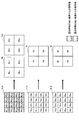
- 4A to 4D are explanatory diagrams for explaining four exemplary methods for acquiring image signals with different exposure amounts.
- the signal acquisition unit 210 generates a first specific component image signal generated through exposure at a first exposure time for a specific color component. And a second specific component image signal generated through exposure at a second exposure time for the specific color component.
- the R component sensor 121 has a set of pixels having long exposure times (long-lived pixels) corresponding to the pixel positions hatched with diagonal lines and an exposure time corresponding to the pixel positions hatched with dots.
- a set of short pixels (short pixels).
- the input specific component image signal I in_R input to the signal acquisition unit 210 includes pixel values from a set of both of these pixels.
- the signal acquisition unit 210 extracts only the signal values (RS 1a , RS 1b , RS 2a , RS 2a , etc.
- the first specific component image signal I RS (RS 1 , RS 2 , RS 3 , RS 4 ,...) Is acquired.
- the signal acquisition unit 210 extracts only the signal values of the long accumulation pixels (RL 1a , RL 1b , RL 2a , RL 2a , etc. From the input specific component image signal I in_R , and resizes as necessary.
- All the pixels of the G component sensor 123 and the B component sensor 125 have a uniform exposure time, and the exposure time is the exposure time of the long accumulation pixel and the short accumulation pixel of the R component sensor 121. It may be equal to either.
- the signal acquisition unit 210 performs resizing and averaging (for example, G value) so that the difference in resolution between the color components is eliminated.
- 1 (G 1a + G 1b + G 1c + G 1d ) / 4)
- the first non-specific component image signal IG is acquired.
- Such resizing may reduce the resolution of the image somewhat, but since image sensors used in recent years have sufficiently high resolution, such a reduction in resolution does not affect the practicality of the image.
- the pixel group having a long exposure time and the pixel group having a short exposure time are spatially alternately arranged in the R component sensor 121, but these pixel groups are arranged in another spatial pattern. May be.
- the R component sensor 121 may perform exposure and imaging in two types of exposure times by a time division method. .
- the pixel group of the R component sensor 121 is exposed for the first exposure time at the first timing, and is exposed for the second exposure time at the second timing.
- the signal acquisition unit 210 acquires the first specific component image signal from the R component sensor 121 at the first timing, and acquires the second specific component image signal from the R component sensor 121 at the second timing. Can do.
- the signal acquisition unit 210 generates a first specific component image signal from a pixel group that is exposed with a first exposure time for a specific color component. And the signal value of the adjacent pixel in the first specific component image signal is added to acquire the second specific component image signal.
- all the pixels of the R component sensor 121, the G component sensor 123, and the B component sensor 125 may have a uniform exposure time.
- the input specific component image signal I in_R input to the signal acquisition unit 210 is directly handled as the first specific component image signal I RS (R 1 , R 2 ,..., R K , R K + 1 ,). Further, the signal acquisition unit 210 uses the signal values S (R 2 , R 3 ,..., R K + 1 , R K + 2 ,...) Of adjacent pixel positions as the signal values at the respective pixel positions of the input specific component image signal I in_R.
- the second specific component image signal I RL (R 1 ′, R 2 ′,..., R K ′, R K + 1 ′,...) Is acquired by adding.
- the second specific component image signal I RL becomes an image signal with a pseudo exposure amount larger than that of the first specific component image signal I RS .
- the signal acquisition unit 210 uses the first input non-specific component image signal I in_G and the second input non-specific component image signal I in_B as they are as the first non-specific component image signal I G. and the second may be treated as a non-specific component image signal I B. Instead, the signal acquisition unit 210 may generate a non-specific component image signal accompanied with a larger exposure amount by adding the signal values of adjacent pixels to the non-specific component image signal. .
- the signal acquisition unit 210 performs the first operation at the first frame rate from the pixel group exposed for the first exposure time for the specific color component.
- the second specific component image signal is acquired by adding the signal values of the first specific component image signal over a plurality of temporally continuous frames.
- all the pixels of the R component sensor 121, the G component sensor 123, and the B component sensor 125 may have a uniform exposure time.
- the input specific component image signal I in_R input to the signal acquisition unit 210 is directly handled as the first specific component image signal I RS (R 1 , R 2 ,..., R K , R K + 1 ,).
- the second specific component image signal I RL (R 1 ′, R 2 ′,..., R K ′, R K + 1 ′,...) is acquired by adding the signal value of in_R for each common pixel position. .
- the second specific component image signal I RL is an image signal with a larger exposure amount than the first specific component image signal I RS .
- the signal acquisition unit 210 uses the first input non-specific component image signal I in_G and the second input non-specific component image signal I in_B as they are as the first non-specific component image signal I G. and the second may be treated as a non-specific component image signal I B. Instead, the signal acquisition unit 210 generates a non-specific component image signal with a larger exposure amount by adding signal values over a plurality of temporally continuous frames for the input non-specific component image signal. Also good.
- the signal acquisition unit 210 receives a specific color component through a filter having the first transmittance, and the first transmittance.
- a first specific component image signal and a second specific component image signal are acquired from an imaging device having a pixel group that receives a specific color component through a filter having a transmittance different from that of the first specific component image signal.
- the input specific component image signal I in_RL based on the light that has passed through the filter 122 having a relatively high transmittance and the input based on the light that has passed through the filter 124 having a relatively low transmittance.
- a specific component image signal I in_RS is shown.
- all the pixels of the R component sensor 121, the G component sensor 123, and the B component sensor 125 may have a uniform exposure time.
- the signal acquisition unit 210 uses the input specific component image signal I in_RS as the first specific component image signal I RS (RS 1 , RS 2 , RS 3 , RS 4 ,...) And the input specific component image signal I in_RL .
- the pixels for the two input specific component image signals I in_RS and I in_RL may be mixed in the single R component sensor 121 as described with reference to FIG. It may be arranged. In the latter case, a filter 122 is attached to one sensor, and a filter 124 is attached to the other sensor.
- the signal acquisition unit 210 treats the input specific component image signals I In_G based on light passed through the filter 126 as the first non-specific component image signal I G, the input specific component image signal based on the light that has passed through the filter 128 I in_B is treated as the second non-specific component image signal I B.
- the transmittance of filters 126 and 128 may be equal to the (relatively low) transmittance of filter 124, or may be equal to the (relatively high) transmittance of filter 122, as shown in FIG. 4D. Good.
- One of the filters 122 and 124 and the filters 126 and 128 may be omitted from the configuration of the image sensor 120.
- the signal acquisition unit 210 has four types of image signals acquired by any of the methods described in this section, that is, the first specific component image signal I RS , the second specific component image signal I RL , and the first non-image signal. a specific component image signal I G and the second non-specific component image signal I B, and outputs to the combining unit 220.
- FIG. 6 shows a graph depicting an example of the relationship between the signal value of the second specific component image signal IRL and the composite weight WRL .
- the combining weight W RL is equal to 1.0.
- the combining weight W RL is monotonically decreasing to zero from 1.0.
- the combining weight W RL is equal to zero.
- the second specific component image signal IRL contributes more to the composite image signal in an image region with a weak R component, which is a specific color component, whereas in an image region with a strong R component, , the first specific component image signal I RS contributes more to the combined image signal.
- the synthesized image signal generated by the synthesizing unit 220 loss of R component gradation is avoided or reduced in both the low signal value region and the high signal value region.
- the graph showing the relationship between the signal value and the composite weight is not limited to the example shown in FIG. 6, and any locus may be drawn as long as it has a tendency to decrease as the signal value increases.
- Combining unit 220 a specific component combined image signal I R generated in this manner is output to the color image generating unit 230.
- FIG. 7 shows an example of a more detailed configuration of the color image generation unit 230 shown in FIG.
- the color image generation unit 230 includes a dynamic range (DR) correction unit 231, a color tone adjustment unit 233, and a multiplexing unit 236.
- DR dynamic range
- the second specific component image signal IRL of the four types of image signals acquired by the signal acquisition unit 210 includes other non-specific component image signals. It involves a larger amount of exposure than the image signal.
- the dynamic range of a specific component combined image signal I R to be inputted to the color image generating section 230 may be greater than the two non-specific component image signals I dynamic range of G and I B. Therefore, DR correcting unit 231, the specific component combined image signal I R, as non-specific component image signal I G and dynamic range of the non-specific component image signal I B are equal to each other, the dynamic of a specific component combined image signal I R Compress the range.
- DR correcting unit 2331 by multiplying the small correction factor than 1 in specific component combined image signal I R, may compress the dynamic range.
- the DR correction unit 231 may linearly correct the signal value using a fixed correction factor corresponding to the ratio of the dynamic range width.
- the DR correction unit 231 may execute nonlinear correction such as gamma correction.
- FIG. 8 is a graph for explaining an example of nonlinear correction for compression of the dynamic range.
- a correction factor curve 232a that can be utilized in correcting an input value from zero to 2.0 to an output value from zero to 1.0.
- the correction factor curve 232a corresponds to a so-called hyper gamma curve.
- DR correcting unit 231 by gamma correction specific component combined image signal I R with a correction factor to draw such a curve, while leaving the gradation in the high signal value region of the R component better, specific component dynamic range of the composite image signal I R can be compressed.
- the correction factor curve 232b in FIG. 8 is a normal gamma curve that does not change the dynamic range between the input value and the output value.
- DR correcting unit 231 may be gamma-corrected even nonspecific component image signal I G and I B according to the correction curve 232b.
- DR correcting unit 231 instead of compressing the dynamic range of a specific component combined image signal I R, the dynamic range are equal to each other of the specific component combined image signal I R, as well as non-specific component image signal I G and I B as you may elongation dynamic range of non-specific component image signal I G and I B.
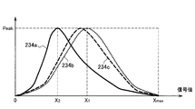
- FIG. 9A is an explanatory diagram for describing an example of a variation in color tone resulting from the synthesis of two specific component image signals.
- the horizontal axis of FIG. 9A represents the dynamic range of each color component from zero to the maximum value Xmax .
- the vertical axis represents the frequency of the signal value.
- a graph 234a represents a distribution of R component signal values
- a graph 234b represents a distribution of G component signal values
- a graph 234c represents a distribution of B component signal values. For example, assuming that the color tone of the observation light is close to white, when the two specific component image signals with different exposure amounts described above are synthesized only for the R component that is the specific color component, only the peak of the R component signal value is obtained.
- Peak of the signal values of the G component and the B component is a non-specific color component is kept in the vicinity of the value X 1. If a color image is displayed without adjusting the color tone as it is, a subject close to white can be displayed as if it was colored with a complementary color of red.
- the color tone adjustment unit 233 adjusts the image signal of at least one color component so as to cancel such variation in color tone.
- the color tone adjuster 233 the tone curve to move the peak of the non-specific component image signal I G and I B in a direction to cancel the change of color tone, is applied to a non-specific component image signal I G and I B.
- Figure 9B by applying a tone curve in a non-specific component image signal I G and I B, after canceling the variation of the color tone shows the distribution of the signal values of three color components.
- a graph 235b represents a distribution of G component signal values
- a graph 235c represents a distribution of B component signal values.
- the peak of the signal values of three color components are all positioned in the vicinity of the signal value X 2.
- the graph 234a is unchanged, i.e. the specific component combined image signal I R to be maintained, the gradation in the high signal value region of the R component is a specific color component to be observed is well integrity.
- the color image generation unit 230 performs, for example, noise reduction, in order to improve the quality of individual color component images or color images at an arbitrary timing in the image signal processing described above.
- a quality enhancement process that may include one or more of white balance adjustment, blur correction, and resolution enhancement may be performed.
- FIG. 10 is a flowchart illustrating an example of the flow of image signal processing according to an embodiment.
- the control unit 240 acquires setting information stored in advance, for example, and sets a specific color component according to the acquired setting information (step S110).
- the signal acquisition unit 210 executes a signal acquisition process to generate one frame of a color image, the first specific component image signal, the second specific component image signal, and two non-specific images
- a component image signal is acquired (step S120).
- the first specific component image signal is accompanied by a first exposure amount for the specific color component.
- the second specific component image signal is accompanied by a second exposure amount different from the first exposure amount for the specific color component.
- the two non-specific component image signals are accompanied by the first exposure amount or the second exposure amount for each of the two non-specific color components.
- the synthesis unit 220 synthesizes the first and second specific component image signals input from the signal acquisition unit 210 with a synthesis weight corresponding to the strength of the specific color component, thereby generating the specific component composite image signal. Is generated (step S160). Assuming that the second exposure amount is larger than the first exposure amount, typically, the combining unit 220 relatively sets the combination weight applied to the second specific component image signal in a pixel having a weak specific color component. The combination weight applied to the first specific component image signal is set to be relatively high for pixels having a high specific color component. Thereby, the reproducibility of the gradation for the specific color component is improved. Then, the synthesis unit 220 outputs the specific component composite image signal and the two non-specific component image signals to the color image generation unit 230.
- the color image generation unit 230 executes a color image generation process to generate a color image signal from the specific component composite image signal and the two non-specific component image signals (step S170).
- a color image generation process to generate a color image signal from the specific component composite image signal and the two non-specific component image signals (step S170).
- An example of a more detailed flow of the color image generation process executed here will be further described later.
- the color image signal generated by the color image generation unit 230 may be output to the display device 53 for displaying a color image, for example, or output to the recorder 65 for recording an image or a moving image. Also good.
- Steps S120 to S170 described above are repeated until the end condition of the image signal processing is satisfied (step S190). For example, when a user input instructing the end of processing is detected via the input device 59, the above-described image signal processing ends.
- FIG. 11A is a flowchart showing a first example of a more detailed flow of the signal acquisition process shown in FIG. The first example corresponds to the scenario described with reference to FIG. 4A.
- the signal acquisition unit 210 a specific color component is exposed in the exposure time E 1 in the image sensor 120 X (e.g., X is R, 1 one of a G or B) from a pixel group
- the first specific component image signal is acquired (step S121).
- the signal acquisition part 210 averages a signal value for every block for N pixels of a 1st specific component image signal (step S122).
- N 2, where N may be any integer.
- the signal acquisition unit 210 the pixel groups of a specific color component X that has been exposed with an exposure time E 2 in the image sensor 120 acquires a second specific component image signal (step S125). And the signal acquisition part 210 averages a signal value for every block for N pixels of a 2nd specific component image signal (step S126).
- FIG. 11B is a flowchart showing a second example of a more detailed flow of the signal acquisition process shown in FIG. The second example corresponds to the scenario described with reference to FIG. 4B.
- the signal acquisition unit 210 the pixel groups of a specific color component X that has been exposed by the exposure time E 1 in the image sensor 120 acquires a first specific component image signal (step S131).
- the signal acquisition unit 210, the non-specific color component Y is exposed by the exposure time E 1 in the image sensor 120, the pixel group of Z, to obtain the corresponding two non specific component image signal (step S133).
- the signal acquisition unit 210 acquires a second specific component image signal by adding the signal values of adjacent pixels in the first specific component image signal (step S135).
- FIG. 11C is a flowchart illustrating a third example of a more detailed flow of the signal acquisition process illustrated in FIG. 10.
- the third example corresponds to the scenario described with reference to FIG. 4C.
- the signal acquisition unit 210 acquires the first specific component image signal of the i-th frame for the specific color component X from the image sensor 120 (step S141).
- the signal acquisition unit 210 acquires the two non-specific component image signals corresponding to the i-th frame for the non-specific color components Y and Z from the image sensor 120 (step S143).
- the signal acquisition unit 210 acquires the first specific component image signal of the (i + 1) th frame for the specific color component X from the image sensor 120 (step S145).
- the signal acquisition unit 210 acquires two non-specific component image signals corresponding to the i + 1-th frame for the non-specific color components Y and Z from the image sensor 120 (step S147).
- the signal acquisition unit 210 adds the signal value of the first specific component image signal over the i-th and i + 1-th frames that are temporally continuous for each pixel, thereby obtaining a second color value for the specific color component X.
- a specific component image signal is acquired (step S149).
- FIG. 11D is a flowchart illustrating a fourth example of a more detailed flow of the signal acquisition process illustrated in FIG. 10.
- the fourth example corresponds to the scenario described with reference to FIG. 4D.
- the signal acquisition unit 210 acquires a first specific component image signal for the specific color component X, which is generated in the image sensor 120 through a filter with transmittance ⁇ 1 (step S151). ).
- the signal acquisition unit 210 acquires two non-specific component image signals corresponding to the non-specific color components Y and Z generated by the image sensor 120 through the filter having the transmittance ⁇ 1 (step S153).
- the signal acquisition unit 210 acquires a second specific component image signal for the specific color component X, which is generated in the image sensor 120 through a filter having a transmittance ⁇ 2 (for example, ⁇ 1 ⁇ 2 ). (Step S155).
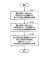
- FIG. 12 is a flowchart showing an example of a more detailed flow of the color image generation process shown in FIG.
- the color image generation unit 230 compresses the dynamic range of the specific component composite image signal so that the dynamic ranges of the specific component composite image signal and the two non-specific component image signals are equal to each other. (Step S171).
- the color image generating unit 230 sets a tone curve for moving the signal peak in the direction of canceling the tone variation so as to cancel the tone variation caused by the synthesis of two specific component image signals having different exposure amounts. This is applied to the two non-specific component image signals (step S173).
- the color image generation unit 230 generates a color image signal from the specific component composite image signal after the color tone adjustment by the color tone adjustment unit 233 and the two non-specific component image signals (step S175).
- the color image generation unit 230 performs any quality improvement such as noise reduction, white balance adjustment, blur correction, or higher resolution at any timing in the color image generation processing. Processing may be performed.
- FIG. 13 shows a graph for explaining typical contrast sensitivity of human vision.
- the horizontal axis of FIG. 13 is the spatial frequency of the texture that appears in the field of view.
- the vertical axis represents the magnitude of contrast sensitivity normalized to a range from zero to one.
- the graph G1 is an example of a CSF (Contrast Sensitivity Function) curve representing the human visual contrast sensitivity with respect to luminance.
- Graph G2 is an example of a CSF curve in the red-green region.
- Graph G3 is an example of a CSF curve in the yellow-blue region.
- the peak of contrast sensitivity of a specific color component in human vision is significantly shifted to the lower band side than the peak of contrast sensitivity of luminance. Accordingly, when the same processing is performed only on a specific color component, compared with a case where HDR synthesis is performed on the three color components uniformly, for example, subjective image quality degradation (perceived by the user) For example, the reduction in resolution) may be smaller. From this point of view, the above-described embodiment for maintaining or enhancing the gradation particularly for the specific color component to be observed is advantageous as compared with the existing method that handles the three color components in common. is there.
- the embodiments of the technology according to the present disclosure have been described in detail with reference to FIGS. 1 to 13.
- the first specific component image signal with the first exposure amount for the specific color component and the second specific component image signal with the second exposure amount different from the first exposure amount are synthesized with a weight according to the strength of the specific color component, and a color image signal is generated based on the specific component composite image signal generated as a result of the combination and the two non-specific component image signals . Therefore, the dynamic range of a specific color component corresponding to a color component that strongly influences the gradation of the subject or a color component that is particularly significant among the gradation of the subject is appropriately adjusted, and the gradation to be observed is lost. Can be effectively reduced.
- the color image is adjusted after the image signal is adjusted so as to cancel the color tone variation caused by the synthesis of the first specific component image signal and the second specific component image signal.
- a signal can be generated. Therefore, it is possible to prevent an undesirable change in color tone due to adjustment of a signal specialized for a specific color component from appearing in a finally output color image.
- a tone curve that moves the peaks of the non-specific component image signal can be applied to cancel the change in color tone. Therefore, for example, the gradation in the high signal value region of the specific color component can be well preserved while preventing undesirable color tone fluctuations.
- the first specific component image signal is generated through exposure at a first exposure time or through a filter having a first transmittance
- the second specific component image signal is , Through exposure at a second exposure time, or through a filter having a second transmittance.
- the gradation of the specific color component can be maintained or enhanced without causing motion blur due to the movement of the subject in the specific component composite image signal and without sacrificing the resolution.
- the first specific component image signal is acquired from a pixel group exposed at a first exposure time
- the second specific component image signal is the first specific component image. It is generated by adding signal values of adjacent pixels in the image signal.
- the second specific component image with a larger exposure amount than the first specific component image signal in a pseudo manner without requiring a special configuration or control for handling two exposure amounts in the imaging apparatus.
- a signal can be acquired.
- the specific color component can be set according to setting information that is dynamically acquired. Therefore, it is possible to dynamically set various color components such as red in normal surgery and specific colors in special light observation as specific color components. The range can be adjusted flexibly.
- an example of an image processing system including a surgical endoscope has been mainly described.
- the technology according to the present disclosure is not limited to such an example, and can be applied to other types of endoscopes such as a capsule endoscope, or other types of medical observation apparatuses such as a microscope.
- the technology according to the present disclosure may be realized as an image processing module (for example, an image processing chip) or a camera module mounted on such a medical observation apparatus.
- the image processing described in this specification may be realized using any of software, hardware, and a combination of software and hardware.
- the program constituting the software is stored in advance in a storage medium (non-transitory medium) provided inside or outside each device.
- Each program is read into a RAM (Random Access Memory) at the time of execution and executed by a processor such as a CPU.
- a color image generation unit that generates a color image signal from the specific component composite image signal generated by the combination unit and the two non-specific component image signals;
- a medical image processing apparatus comprising: (2) The color image generation unit is configured to output the specific component composite image signal or the two non-specific images so as to cancel a color tone variation caused by the combination of the first specific component image signal and the second specific component image signal.
- the medical image processing apparatus which adjusts component image signals.
- the color image generation unit adjusts the non-specific component image signal by applying to the non-specific component image signal a tone curve that moves a peak of the non-specific component image signal in a direction that cancels the variation in the color tone.
- the medical image processing apparatus according to (2).
- the signal acquisition unit generates the first specific component image signal generated through the exposure at the first exposure time for the specific color component, and the exposure at the second exposure time for the specific color component.
- the medical image processing apparatus according to any one of (1) to (3), wherein the generated second specific component image signal is acquired.
- the signal acquisition unit includes an imaging device including both a pixel group exposed for the first color exposure for the specific color component and a pixel group exposed for the second exposure time for the specific color component.
- the signal acquisition unit is a pixel group for the specific color component, and is exposed at the first exposure time at a first timing and is exposed at the second exposure time at a second timing.
- the medical image processing apparatus according to (4), wherein the first specific component image signal and the second specific component image signal are acquired from the pixel group.
- the signal acquisition unit acquires the first specific component image signal from a pixel group that is exposed with the first exposure time for the specific color component, and adjacent pixels in the first specific component image signal 4.
- the medical image processing apparatus according to any one of (1) to (3), wherein the second specific component image signal is acquired by adding the signal values of.
- the signal acquisition unit acquires the first specific component image signal at a first frame rate from a pixel group exposed for the first exposure time for the specific color component, and a plurality of temporally continuous signals
- the medical image processing according to any one of (1) to (3), wherein the second specific component image signal is acquired by adding signal values of the first specific component image signal over a plurality of frames. apparatus.
- the signal acquisition unit receives a pixel group that receives the specific color component through a filter having a first transmittance, and receives the specific color component through a filter having a transmittance different from the first transmittance.
- the medical image according to any one of (1) to (3), wherein the first specific component image signal and the second specific component image signal are obtained from an imaging apparatus having both pixel groups. Processing equipment.
- the second exposure amount is greater than the first exposure amount,
- the synthesizing unit applies a relatively high synthesis weight to the second specific component image signal in the pixel having a weak specific color component, and a relatively high synthesis weight in the pixel having a strong specific color component. Is applied to the first specific component image signal,
- the medical image processing apparatus according to any one of (1) to (9).
- the medical image processing apparatus according to any one of (1) to (10), wherein the specific color component is a red component.
- a control unit that acquires setting information associated with a color component to be observed and sets the specific color component according to the acquired setting information;
- the medical image processing apparatus according to any one of (1) to (10), further comprising: (13) An imaging device for imaging a subject; An image processing device that processes one or more image signals acquired from the imaging device to generate a color image signal;
- the image processing apparatus includes: A first specific component image signal with a first exposure amount for a specific color component; a second specific component image with a second exposure amount different from the first exposure amount for the specific color component;
- a signal acquisition unit for acquiring a signal and two non-specific component image signals respectively corresponding to two color components different from the specific color component;
- a combining unit that generates a specific component composite image signal by combining the first specific component image signal and the second specific component image signal with a weight according to the strength of the specific color component;
- a color image generation unit that generates
- a medical image processing method comprising: (15) A processor for controlling the medical image processing apparatus; A first specific component image signal with a first exposure amount for a specific color component; a second specific component image with a second exposure amount different from the first exposure amount for the specific color component; A signal acquisition unit for acquiring a signal and two non-specific component image signals respectively corresponding to two color components different from the specific color component; A combining unit that generates a specific component composite image signal
Abstract
Description
なお、上記の効果は必ずしも限定的なものではなく、上記の効果と共に、又は上記の効果に代えて、本明細書に示されたいずれかの効果、又は本明細書から把握され得る他の効果が奏されてもよい。 According to the technology according to the present disclosure, it is possible to reduce a risk that a gradation of a specific color component of a subject to be observed in medical work is lost, and to provide a clearer subject image than before. It becomes.
Note that the above effects are not necessarily limited, and any of the effects shown in the present specification, or other effects that can be grasped from the present specification, together with or in place of the above effects. May be played.
1.システムの概要
2.装置の構成例
2-1.撮像装置
2-2.画像処理装置
3.詳細な実施例
3-1.画像信号の取得
3-2.特定成分合成画像信号の生成
3-3.カラー画像の生成
4.処理の流れ
4-1.全体的な流れ
4-2.信号取得処理
4-3.カラー画像生成処理
5.人間の視覚のコントラスト感度
6.まとめ The description will be given in the following order.
1. 1. System overview Example of device configuration 2-1. Imaging device 2-2. 2. Image processing device Detailed Example 3-1. Acquisition of image signal 3-2. Generation of specific component composite image signal 3-3. 3. Generation of color image Flow of processing 4-1. Overall flow 4-2. Signal acquisition processing 4-3. 4. Color
本節では、本開示に係る技術が適用され得る例示的なシステムの概要を説明する。図1は、一実施形態に係る医療用画像処理システム1の概略的な構成の一例を示している。医療用画像処理システム1は、内視鏡下手術システムである。図1の例では、術者(医師)3が、医療用画像処理システム1を用いて、患者ベッド5上の患者7に内視鏡下手術を行っている。医療用画像処理システム1は、内視鏡10と、その他の術具30と、内視鏡10を支持する支持アーム装置40と、内視鏡下手術のための様々な装置が搭載されたカート50と、から構成される。 <1. System overview>
This section outlines an exemplary system to which the technology according to the present disclosure can be applied. FIG. 1 shows an example of a schematic configuration of a medical
図1に例示した医療用画像処理システム1の構成要素の中で、特に、撮像装置の役割を有するカメラヘッド13、及び画像処理装置の役割を有するCCU51が、被写体の撮像及び撮像画像に基づく画像の表示に主に関与する。そこで、本節では、これら2つの装置の具体的な構成について詳細に説明する。 <2. Example of device configuration>
Among the components of the medical
図2には、撮像装置であるカメラヘッド13の構成の一例が示されている。図2を参照すると、カメラヘッド13は、光学系110、イメージセンサ120、通信部130及び駆動系140を備える。 [2-1. Imaging device]
FIG. 2 shows an example of the configuration of the
図2には、画像処理装置であるCCU51の構成の一例もまた示されている。図2を参照すると、CCU51は、信号取得部210、合成部220、カラー画像生成部230及び制御部240を備える。 [2-2. Image processing apparatus]
FIG. 2 also shows an example of the configuration of the
本節では、上述したCCU51の各部の構成についてのより詳細な実施例を説明する。ここでは、説明のための例として、特定色成分は赤(R)成分であるものとする。しかしながら、特定色成分が他の色である場合にも、以下の説明は同等に適用可能であることに留意されたい。 <3. Detailed Examples>
In this section, a more detailed example of the configuration of each part of the
図3は、図2に示した信号取得部210へ入力される画像信号、及び信号取得部210から出力される画像信号について概略的に説明するための説明図である。図3には、カメラヘッド13のイメージセンサ120の構成の一例も示されている。ここでは、イメージセンサ120は、3板式センサであり、R成分用センサ121、G成分用センサ123及びB成分用センサ125を含む。 [3-1. Acquisition of image signal]
FIG. 3 is an explanatory diagram schematically illustrating the image signal input to the
図4Aに示した第1の手法によれば、信号取得部210は、特定の色成分について第1の露光時間での露光を通じて生成される第1の特定成分画像信号、及び、特定の色成分について第2の露光時間での露光を通じて生成される第2の特定成分画像信号を取得する。 (1) First Method According to the first method shown in FIG. 4A, the
図4Bに示した第2の手法によれば、信号取得部210は、特定の色成分について第1の露光時間で露光される画素群から第1の特定成分画像信号を取得し、及び、第1の特定成分画像信号における隣り合う画素の信号値を加算することにより、第2の特定成分画像信号を取得する。 (2) Second Method According to the second method shown in FIG. 4B, the
図4Cに示した第3の手法によれば、信号取得部210は、特定色成分について第1の露光時間で露光される画素群から第1のフレームレートで第1の特定成分画像信号を取得し、及び、時間的に連続する複数のフレームにわたる第1の特定成分画像信号の信号値の加算により、第2の特定成分画像信号を取得する。 (3) Third Method According to the third method illustrated in FIG. 4C, the
図4Dに示した第4の手法によれば、信号取得部210は、第1の透過率を有するフィルタを通じて特定色成分を受光する画素群と、第1の透過率とは異なる透過率を有するフィルタを通じて特定の色成分を受光する画素群とを有する撮像装置から、第1の特定成分画像信号及び第2の特定成分画像信号を取得する。 (4) Fourth Method According to the fourth method illustrated in FIG. 4D, the
次に、図5及び図6を用いて、合成部220における信号の合成についてあらためて説明する。図5の上段において左から現れる矢印は第1の特定成分画像信号IRSを、下段において左から現れる矢印は第2の特定成分画像信号IRLを表現している。合成部220は、第1の特定成分画像信号IRSに合成重みWRSを、第2の特定成分画像信号IRLに合成重みWRLを適用する。合成重みWRSと合成重みWRLとの和は1に等しく、合成重みWRS及びWRLは共にゼロ以上1以下の実数である。合成重みWRS及びWRLの値は可変的であり、合成部220はこれら重みの値を、画素ごとに、特定成分画像信号の信号値(即ち、特定色成分の強さ)に依存して決定する。 [3-2. Generation of specific component composite image signal]
Next, signal synthesis in the
図7は、図2に示したカラー画像生成部230のより詳細な構成の一例を示している。図7を参照すると、カラー画像生成部230は、ダイナミックレンジ(DR)補正部231、色調調整部233及び多重化部236を有する。 [3-3. Color image generation]
FIG. 7 shows an example of a more detailed configuration of the color
ある実施例によれば、信号取得部210により取得される4種類の画像信号のうち第2の特定成分画像信号IRLのみが、非特定成分画像信号を含む他の画像信号よりも多くの露光量を伴う。この場合、カラー画像生成部230へ入力される特定成分合成画像信号IRのダイナミックレンジは、2つの非特定成分画像信号IG及びIBのダイナミックレンジよりも大きくなり得る。そこで、DR補正部231は、特定成分合成画像信号IR、非特定成分画像信号IG及び非特定成分画像信号IBのダイナミックレンジが互いに等しくなるように、特定成分合成画像信号IRのダイナミックレンジを圧縮する。より具体的には、DR補正部231は、1よりも小さい補正率を特定成分合成画像信号IRに乗算することにより、そのダイナミックレンジを圧縮し得る。例えば、DR補正部231は、ダイナミックレンジの幅の比に相当する固定的な補正率を用いて、信号値を線型的に補正してもよい。その代わりに、DR補正部231は、ガンマ補正などの非線型的な補正を実行してもよい。 (1) Dynamic Range Correction According to an embodiment, only the second specific component image signal IRL of the four types of image signals acquired by the
既に述べたように、合成部220における互いに異なる露光量を伴う2つの特定成分画像信号の合成は、より多くの露光量を伴う画像信号のダイナミックレンジの全体から見ると、信号値のピークを下方へずらすように作用する。そして、特定色成分の信号値のみが押し下げられた場合、最終的に得られるはずのカラー画像の色調が意図に反して変動し得る。 (2) Color Tone Adjustment As described above, the synthesis of two specific component image signals with different exposure amounts in the
多重化部236は、色調調整部233による色調調整後の特定成分合成画像信号IR並びに2つの非特定成分画像信号IG及びIBを多重化することによりカラー画像信号Ioutを生成し、生成したカラー画像信号Ioutを表示装置53又はレコーダ65へ出力する。 (3)
本節では、上述した実施形態においてCCU51により実行され得る処理の流れの例を、いくつかのフローチャートを用いて説明する。なお、フローチャートに複数の処理ステップが記述されるが、それら処理ステップは、必ずしもフローチャートに示された順序で実行されなくてもよい。いくつかの処理ステップは、並列的に実行されてもよい。また、追加的な処理ステップが採用されてもよく、一部の処理ステップが省略されてもよい。 <4. Flow of processing>
In this section, an example of a flow of processing that can be executed by the
図10は、一実施形態に係る画像信号処理の流れの一例を示すフローチャートである。図10を参照すると、まず、制御部240は、例えば予め記憶される設定情報を取得し、取得した設定情報に応じて特定色成分を設定する(ステップS110)。 [4-1. Overall flow]
FIG. 10 is a flowchart illustrating an example of the flow of image signal processing according to an embodiment. Referring to FIG. 10, first, the
(1)第1の例
図11Aは、図10に示した信号取得処理のより詳細な流れの第1の例を示すフローチャートである。第1の例は、図4Aを用いて説明したシナリオに対応する。 [4-2. Signal acquisition processing]
(1) First Example FIG. 11A is a flowchart showing a first example of a more detailed flow of the signal acquisition process shown in FIG. The first example corresponds to the scenario described with reference to FIG. 4A.
図11Bは、図10に示した信号取得処理のより詳細な流れの第2の例を示すフローチャートである。第2の例は、図4Bを用いて説明したシナリオに対応する。 (2) Second Example FIG. 11B is a flowchart showing a second example of a more detailed flow of the signal acquisition process shown in FIG. The second example corresponds to the scenario described with reference to FIG. 4B.
図11Cは、図10に示した信号取得処理のより詳細な流れの第3の例を示すフローチャートである。第3の例は、図4Cを用いて説明したシナリオに対応する。 (3) Third Example FIG. 11C is a flowchart illustrating a third example of a more detailed flow of the signal acquisition process illustrated in FIG. 10. The third example corresponds to the scenario described with reference to FIG. 4C.
図11Dは、図10に示した信号取得処理のより詳細な流れの第4の例を示すフローチャートである。第4の例は、図4Dを用いて説明したシナリオに対応する。 (4) Fourth Example FIG. 11D is a flowchart illustrating a fourth example of a more detailed flow of the signal acquisition process illustrated in FIG. 10. The fourth example corresponds to the scenario described with reference to FIG. 4D.
図12は、図10に示したカラー画像生成処理のより詳細な流れの一例を示すフローチャートである。 [4-3. Color image generation processing]
FIG. 12 is a flowchart showing an example of a more detailed flow of the color image generation process shown in FIG.
図13は、人間の視覚の典型的なコントラスト感度について説明するためのグラフを示している。図13の横軸は、視野に現れるテキスチャの空間周波数である。縦軸は、ゼロから1までの範囲に正規化された、コントラスト感度の大きさである。グラフG1は、輝度についての人間の視覚のコントラスト感度を表すCSF(Contrast Sensitivity Function)曲線の一例である。グラフG2は、赤-緑領域におけるCSF曲線の一例である。グラフG3は、黄-青領域におけるCSF曲線の一例である。図13から理解されることとして、人間の視覚の、特定色成分のコントラスト感度のピークは、輝度のコントラスト感度のピークよりも低帯域側に有意にズレている。従って、3つの色成分について画一的に例えばHDR合成をした場合と比較して、特定の色成分に限って同様の処理をした場合には、ユーザにより感知される主観的な画質の劣化(例えば、解像感の低下)はより小さくて済む。こうした観点からも、観察されるべき特定色成分を特に対象として階調を維持し又は強調しようとする上述した実施形態は、3つの色成分を共通的に扱う既存の手法と比較して有利である。 <5. Contrast sensitivity of human vision>
FIG. 13 shows a graph for explaining typical contrast sensitivity of human vision. The horizontal axis of FIG. 13 is the spatial frequency of the texture that appears in the field of view. The vertical axis represents the magnitude of contrast sensitivity normalized to a range from zero to one. The graph G1 is an example of a CSF (Contrast Sensitivity Function) curve representing the human visual contrast sensitivity with respect to luminance. Graph G2 is an example of a CSF curve in the red-green region. Graph G3 is an example of a CSF curve in the yellow-blue region. As understood from FIG. 13, the peak of contrast sensitivity of a specific color component in human vision is significantly shifted to the lower band side than the peak of contrast sensitivity of luminance. Accordingly, when the same processing is performed only on a specific color component, compared with a case where HDR synthesis is performed on the three color components uniformly, for example, subjective image quality degradation (perceived by the user) For example, the reduction in resolution) may be smaller. From this point of view, the above-described embodiment for maintaining or enhancing the gradation particularly for the specific color component to be observed is advantageous as compared with the existing method that handles the three color components in common. is there.
ここまで、図1~図13を用いて本開示に係る技術の実施形態について詳しく説明した。上述した実施形態によれば、特定色成分についての第1の露光量を伴う第1の特定成分画像信号及び第1の露光量とは異なる第2の露光量を伴う第2の特定成分画像信号が、特定色成分の強さに応じた重みで合成され、当該合成の結果として生成される特定成分合成画像信号と、2つの非特定成分画像信号とに基づいて、カラー画像信号が生成される。従って、被写体の階調に強く影響する色成分又は被写体の階調の中で特に意味を持つ色成分に相当する特定色成分のダイナミックレンジを適切に調整し、観察されるべき階調が欠損してしまうリスクを効果的に低減することができる。 <6. Summary>
So far, the embodiments of the technology according to the present disclosure have been described in detail with reference to FIGS. 1 to 13. According to the embodiment described above, the first specific component image signal with the first exposure amount for the specific color component and the second specific component image signal with the second exposure amount different from the first exposure amount. Are synthesized with a weight according to the strength of the specific color component, and a color image signal is generated based on the specific component composite image signal generated as a result of the combination and the two non-specific component image signals . Therefore, the dynamic range of a specific color component corresponding to a color component that strongly influences the gradation of the subject or a color component that is particularly significant among the gradation of the subject is appropriately adjusted, and the gradation to be observed is lost. Can be effectively reduced.
(1)
特定の色成分についての第1の露光量を伴う第1の特定成分画像信号、前記特定の色成分についての前記第1の露光量とは異なる第2の露光量を伴う第2の特定成分画像信号、及び、前記特定の色成分とは異なる2つの色成分にそれぞれ対応する2つの非特定成分画像信号、を取得する信号取得部と、
前記第1の特定成分画像信号及び前記第2の特定成分画像信号を前記特定の色成分の強さに応じた重みで合成することにより特定成分合成画像信号を生成する合成部と、
前記合成部により生成される前記特定成分合成画像信号及び前記2つの非特定成分画像信号からカラー画像信号を生成するカラー画像生成部と、
を備える医療用画像処理装置。
(2)
前記カラー画像生成部は、前記第1の特定成分画像信号及び前記第2の特定成分画像信号の前記合成に起因する色調の変動を打ち消すように、前記特定成分合成画像信号又は前記2つの非特定成分画像信号を調整する、前記(1)に記載の医療用画像処理装置。
(3)
前記カラー画像生成部は、前記色調の前記変動を打ち消す方向に前記非特定成分画像信号のピークを移動させるトーンカーブを前記非特定成分画像信号に適用することにより、前記非特定成分画像信号を調整する、前記(2)に記載の医療用画像処理装置。
(4)
前記信号取得部は、前記特定の色成分について第1の露光時間での露光を通じて生成される前記第1の特定成分画像信号、及び、前記特定の色成分について第2の露光時間での露光を通じて生成される前記第2の特定成分画像信号を取得する、前記(1)~(3)のいずれか1項に記載の医療用画像処理装置。
(5)
前記信号取得部は、前記特定の色成分について前記第1の露光時間で露光される画素群及び前記特定の色成分について前記第2の露光時間で露光される画素群の双方を有する撮像装置から、前記第1の特定成分画像信号及び前記第2の特定成分画像信号を取得する、前記(4)に記載の医療用画像処理装置。
(6)
前記信号取得部は、前記特定の色成分についての画素群であって、第1のタイミングにて前記第1の露光時間で露光され及び第2のタイミングにて前記第2の露光時間で露光される当該画素群から、前記第1の特定成分画像信号及び前記第2の特定成分画像信号を取得する、前記(4)に記載の医療用画像処理装置。
(7)
前記信号取得部は、前記特定の色成分について第1の露光時間で露光される画素群から前記第1の特定成分画像信号を取得し、及び、前記第1の特定成分画像信号における隣り合う画素の信号値を加算することにより、前記第2の特定成分画像信号を取得する、前記(1)~(3)のいずれか1項に記載の医療用画像処理装置。
(8)
前記信号取得部は、前記特定の色成分について第1の露光時間で露光される画素群から第1のフレームレートで前記第1の特定成分画像信号を取得し、及び、時間的に連続する複数のフレームにわたる前記第1の特定成分画像信号の信号値の加算により、前記第2の特定成分画像信号を取得する、前記(1)~(3)のいずれか1項に記載の医療用画像処理装置。
(9)
前記信号取得部は、第1の透過率を有するフィルタを通じて前記特定の色成分を受光する画素群、及び前記第1の透過率とは異なる透過率を有するフィルタを通じて前記特定の色成分を受光する画素群の双方を有する撮像装置から、前記第1の特定成分画像信号及び前記第2の特定成分画像信号を取得する、前記(1)~(3)のいずれか1項に記載の医療用画像処理装置。
(10)
前記第2の露光量は、前記第1の露光量よりも多く、
前記合成部は、前記特定の色成分の弱い画素において、相対的に高い合成重みを前記第2の特定成分画像信号に適用し、前記特定の色成分の強い画素において、相対的に高い合成重みを前記第1の特定成分画像信号に適用する、
前記(1)~(9)のいずれか1項に記載の医療用画像処理装置。
(11)
前記特定の色成分は、赤成分である、前記(1)~(10)のいずれか1項に記載の医療用画像処理装置。
(12)
観察対象の色成分に関連付けられる設定情報を取得し、取得した設定情報に応じて前記特定の色成分を設定する制御部、
をさらに備える、前記(1)~(10)のいずれか1項に記載の医療用画像処理装置。
(13)
被写体を撮像する撮像装置と、
前記撮像装置から取得される1つ以上の画像信号を処理してカラー画像信号を生成する画像処理装置と、
を含み、
前記画像処理装置は、
特定の色成分についての第1の露光量を伴う第1の特定成分画像信号、前記特定の色成分についての前記第1の露光量とは異なる第2の露光量を伴う第2の特定成分画像信号、及び、前記特定の色成分とは異なる2つの色成分にそれぞれ対応する2つの非特定成分画像信号、を取得する信号取得部と、
前記第1の特定成分画像信号及び前記第2の特定成分画像信号を前記特定の色成分の強さに応じた重みで合成することにより特定成分合成画像信号を生成する合成部と、
前記合成部により生成される前記特定成分合成画像信号及び前記2つの非特定成分画像信号からカラー画像信号を生成するカラー画像生成部と、
を備える、
医療用画像処理システム。
(14)
特定の色成分についての第1の露光量を伴う第1の特定成分画像信号を取得することと、
前記特定の色成分についての前記第1の露光量とは異なる第2の露光量を伴う第2の特定成分画像信号を取得することと、
前記特定の色成分とは異なる2つの色成分にそれぞれ対応する2つの非特定成分画像信号を取得することと、
前記第1の特定成分画像信号及び前記第2の特定成分画像信号を前記特定の色成分の強さに応じた重みで合成することにより特定成分合成画像信号を生成することと、
前記合成により生成される前記特定成分合成画像信号及び前記2つの非特定成分画像信号からカラー画像信号を生成することと、
を含む医療用画像処理方法。
(15)
医療用画像処理装置を制御するプロセッサを、
特定の色成分についての第1の露光量を伴う第1の特定成分画像信号、前記特定の色成分についての前記第1の露光量とは異なる第2の露光量を伴う第2の特定成分画像信号、及び、前記特定の色成分とは異なる2つの色成分にそれぞれ対応する2つの非特定成分画像信号、を取得する信号取得部と、
前記第1の特定成分画像信号及び前記第2の特定成分画像信号を前記特定の色成分の強さに応じた重みで合成することにより特定成分合成画像信号を生成する合成部と、
前記合成部により生成される前記特定成分合成画像信号及び前記2つの非特定成分画像信号からカラー画像信号を生成するカラー画像生成部と、
として機能させるためのプログラム。 The following configurations also belong to the technical scope of the present disclosure.
(1)
A first specific component image signal with a first exposure amount for a specific color component; a second specific component image with a second exposure amount different from the first exposure amount for the specific color component; A signal acquisition unit for acquiring a signal and two non-specific component image signals respectively corresponding to two color components different from the specific color component;
A combining unit that generates a specific component composite image signal by combining the first specific component image signal and the second specific component image signal with a weight according to the strength of the specific color component;
A color image generation unit that generates a color image signal from the specific component composite image signal generated by the combination unit and the two non-specific component image signals;
A medical image processing apparatus comprising:
(2)
The color image generation unit is configured to output the specific component composite image signal or the two non-specific images so as to cancel a color tone variation caused by the combination of the first specific component image signal and the second specific component image signal. The medical image processing apparatus according to (1), which adjusts component image signals.
(3)
The color image generation unit adjusts the non-specific component image signal by applying to the non-specific component image signal a tone curve that moves a peak of the non-specific component image signal in a direction that cancels the variation in the color tone. The medical image processing apparatus according to (2).
(4)
The signal acquisition unit generates the first specific component image signal generated through the exposure at the first exposure time for the specific color component, and the exposure at the second exposure time for the specific color component. The medical image processing apparatus according to any one of (1) to (3), wherein the generated second specific component image signal is acquired.
(5)
The signal acquisition unit includes an imaging device including both a pixel group exposed for the first color exposure for the specific color component and a pixel group exposed for the second exposure time for the specific color component. The medical image processing apparatus according to (4), wherein the first specific component image signal and the second specific component image signal are acquired.
(6)
The signal acquisition unit is a pixel group for the specific color component, and is exposed at the first exposure time at a first timing and is exposed at the second exposure time at a second timing. The medical image processing apparatus according to (4), wherein the first specific component image signal and the second specific component image signal are acquired from the pixel group.
(7)
The signal acquisition unit acquires the first specific component image signal from a pixel group that is exposed with the first exposure time for the specific color component, and adjacent pixels in the first specific component image signal 4. The medical image processing apparatus according to any one of (1) to (3), wherein the second specific component image signal is acquired by adding the signal values of.
(8)
The signal acquisition unit acquires the first specific component image signal at a first frame rate from a pixel group exposed for the first exposure time for the specific color component, and a plurality of temporally continuous signals The medical image processing according to any one of (1) to (3), wherein the second specific component image signal is acquired by adding signal values of the first specific component image signal over a plurality of frames. apparatus.
(9)
The signal acquisition unit receives a pixel group that receives the specific color component through a filter having a first transmittance, and receives the specific color component through a filter having a transmittance different from the first transmittance. The medical image according to any one of (1) to (3), wherein the first specific component image signal and the second specific component image signal are obtained from an imaging apparatus having both pixel groups. Processing equipment.
(10)
The second exposure amount is greater than the first exposure amount,
The synthesizing unit applies a relatively high synthesis weight to the second specific component image signal in the pixel having a weak specific color component, and a relatively high synthesis weight in the pixel having a strong specific color component. Is applied to the first specific component image signal,
The medical image processing apparatus according to any one of (1) to (9).
(11)
The medical image processing apparatus according to any one of (1) to (10), wherein the specific color component is a red component.
(12)
A control unit that acquires setting information associated with a color component to be observed and sets the specific color component according to the acquired setting information;
The medical image processing apparatus according to any one of (1) to (10), further comprising:
(13)
An imaging device for imaging a subject;
An image processing device that processes one or more image signals acquired from the imaging device to generate a color image signal;
Including
The image processing apparatus includes:
A first specific component image signal with a first exposure amount for a specific color component; a second specific component image with a second exposure amount different from the first exposure amount for the specific color component; A signal acquisition unit for acquiring a signal and two non-specific component image signals respectively corresponding to two color components different from the specific color component;
A combining unit that generates a specific component composite image signal by combining the first specific component image signal and the second specific component image signal with a weight according to the strength of the specific color component;
A color image generation unit that generates a color image signal from the specific component composite image signal generated by the combination unit and the two non-specific component image signals;
Comprising
Medical image processing system.
(14)
Obtaining a first specific component image signal with a first exposure amount for a specific color component;
Obtaining a second specific component image signal with a second exposure amount different from the first exposure amount for the specific color component;
Obtaining two non-specific component image signals respectively corresponding to two color components different from the specific color component;
Generating a specific component composite image signal by combining the first specific component image signal and the second specific component image signal with a weight according to the strength of the specific color component;
Generating a color image signal from the specific component composite image signal generated by the combination and the two non-specific component image signals;
A medical image processing method comprising:
(15)
A processor for controlling the medical image processing apparatus;
A first specific component image signal with a first exposure amount for a specific color component; a second specific component image with a second exposure amount different from the first exposure amount for the specific color component; A signal acquisition unit for acquiring a signal and two non-specific component image signals respectively corresponding to two color components different from the specific color component;
A combining unit that generates a specific component composite image signal by combining the first specific component image signal and the second specific component image signal with a weight according to the strength of the specific color component;
A color image generation unit that generates a color image signal from the specific component composite image signal generated by the combination unit and the two non-specific component image signals;
Program to function as.
13 カメラヘッド(撮像装置)
51 CCU(画像処理装置)
53 モニタ(表示装置)
210 信号取得部
220 合成部
230 カラー画像生成部
240 制御部 1 Medical
51 CCU (Image Processing Unit)
53 Monitor (display device)
210
Claims (15)
- 特定の色成分についての第1の露光量を伴う第1の特定成分画像信号、前記特定の色成分についての前記第1の露光量とは異なる第2の露光量を伴う第2の特定成分画像信号、及び、前記特定の色成分とは異なる2つの色成分にそれぞれ対応する2つの非特定成分画像信号、を取得する信号取得部と、
前記第1の特定成分画像信号及び前記第2の特定成分画像信号を前記特定の色成分の強さに応じた重みで合成することにより特定成分合成画像信号を生成する合成部と、
前記合成部により生成される前記特定成分合成画像信号及び前記2つの非特定成分画像信号からカラー画像信号を生成するカラー画像生成部と、
を備える医療用画像処理装置。 A first specific component image signal with a first exposure amount for a specific color component; a second specific component image with a second exposure amount different from the first exposure amount for the specific color component; A signal acquisition unit for acquiring a signal and two non-specific component image signals respectively corresponding to two color components different from the specific color component;
A combining unit that generates a specific component composite image signal by combining the first specific component image signal and the second specific component image signal with a weight according to the strength of the specific color component;
A color image generation unit that generates a color image signal from the specific component composite image signal generated by the combination unit and the two non-specific component image signals;
A medical image processing apparatus comprising: - 前記カラー画像生成部は、前記第1の特定成分画像信号及び前記第2の特定成分画像信号の前記合成に起因する色調の変動を打ち消すように、前記特定成分合成画像信号又は前記2つの非特定成分画像信号を調整する、請求項1に記載の医療用画像処理装置。 The color image generation unit is configured to output the specific component composite image signal or the two non-specific images so as to cancel a color tone variation caused by the combination of the first specific component image signal and the second specific component image signal. The medical image processing apparatus according to claim 1, wherein the component image signal is adjusted.
- 前記カラー画像生成部は、前記色調の前記変動を打ち消す方向に前記非特定成分画像信号のピークを移動させるトーンカーブを前記非特定成分画像信号に適用することにより、前記非特定成分画像信号を調整する、請求項2に記載の医療用画像処理装置。 The color image generation unit adjusts the non-specific component image signal by applying to the non-specific component image signal a tone curve that moves a peak of the non-specific component image signal in a direction that cancels the variation in the color tone. The medical image processing apparatus according to claim 2.
- 前記信号取得部は、前記特定の色成分について第1の露光時間での露光を通じて生成される前記第1の特定成分画像信号、及び、前記特定の色成分について第2の露光時間での露光を通じて生成される前記第2の特定成分画像信号を取得する、請求項1に記載の医療用画像処理装置。 The signal acquisition unit generates the first specific component image signal generated through the exposure at the first exposure time for the specific color component, and the exposure at the second exposure time for the specific color component. The medical image processing apparatus according to claim 1, wherein the second specific component image signal to be generated is acquired.
- 前記信号取得部は、前記特定の色成分について前記第1の露光時間で露光される画素群及び前記特定の色成分について前記第2の露光時間で露光される画素群の双方を有する撮像装置から、前記第1の特定成分画像信号及び前記第2の特定成分画像信号を取得する、請求項4に記載の医療用画像処理装置。 The signal acquisition unit includes an imaging device including both a pixel group exposed for the first color exposure for the specific color component and a pixel group exposed for the second exposure time for the specific color component. The medical image processing apparatus according to claim 4, wherein the first specific component image signal and the second specific component image signal are acquired.
- 前記信号取得部は、前記特定の色成分についての画素群であって、第1のタイミングにて前記第1の露光時間で露光され及び第2のタイミングにて前記第2の露光時間で露光される当該画素群から、前記第1の特定成分画像信号及び前記第2の特定成分画像信号を取得する、請求項4に記載の医療用画像処理装置。 The signal acquisition unit is a pixel group for the specific color component, and is exposed at the first exposure time at a first timing and is exposed at the second exposure time at a second timing. The medical image processing apparatus according to claim 4, wherein the first specific component image signal and the second specific component image signal are acquired from the pixel group.
- 前記信号取得部は、前記特定の色成分について第1の露光時間で露光される画素群から前記第1の特定成分画像信号を取得し、及び、前記第1の特定成分画像信号における隣り合う画素の信号値を加算することにより、前記第2の特定成分画像信号を取得する、請求項1に記載の医療用画像処理装置。 The signal acquisition unit acquires the first specific component image signal from a pixel group that is exposed with the first exposure time for the specific color component, and adjacent pixels in the first specific component image signal The medical image processing apparatus according to claim 1, wherein the second specific component image signal is acquired by adding the signal values of.
- 前記信号取得部は、前記特定の色成分について第1の露光時間で露光される画素群から第1のフレームレートで前記第1の特定成分画像信号を取得し、及び、時間的に連続する複数のフレームにわたる前記第1の特定成分画像信号の信号値の加算により、前記第2の特定成分画像信号を取得する、請求項1に記載の医療用画像処理装置。 The signal acquisition unit acquires the first specific component image signal at a first frame rate from a pixel group exposed for the first exposure time for the specific color component, and a plurality of temporally continuous signals The medical image processing apparatus according to claim 1, wherein the second specific component image signal is acquired by adding signal values of the first specific component image signal over a plurality of frames.
- 前記信号取得部は、第1の透過率を有するフィルタを通じて前記特定の色成分を受光する画素群、及び前記第1の透過率とは異なる透過率を有するフィルタを通じて前記特定の色成分を受光する画素群の双方を有する撮像装置から、前記第1の特定成分画像信号及び前記第2の特定成分画像信号を取得する、請求項1に記載の医療用画像処理装置。 The signal acquisition unit receives a pixel group that receives the specific color component through a filter having a first transmittance, and receives the specific color component through a filter having a transmittance different from the first transmittance. The medical image processing apparatus according to claim 1, wherein the first specific component image signal and the second specific component image signal are acquired from an imaging apparatus having both pixel groups.
- 前記第2の露光量は、前記第1の露光量よりも多く、
前記合成部は、前記特定の色成分の弱い画素において、相対的に高い合成重みを前記第2の特定成分画像信号に適用し、前記特定の色成分の強い画素において、相対的に高い合成重みを前記第1の特定成分画像信号に適用する、
請求項1に記載の医療用画像処理装置。 The second exposure amount is greater than the first exposure amount,
The synthesizing unit applies a relatively high synthesis weight to the second specific component image signal in the pixel having a weak specific color component, and a relatively high synthesis weight in the pixel having a strong specific color component. Is applied to the first specific component image signal,
The medical image processing apparatus according to claim 1. - 前記特定の色成分は、赤成分である、請求項1に記載の医療用画像処理装置。 The medical image processing apparatus according to claim 1, wherein the specific color component is a red component.
- 観察対象の色成分に関連付けられる設定情報を取得し、取得した設定情報に応じて前記特定の色成分を設定する制御部、
をさらに備える、請求項1に記載の医療用画像処理装置。 A control unit that acquires setting information associated with a color component to be observed and sets the specific color component according to the acquired setting information;
The medical image processing apparatus according to claim 1, further comprising: - 被写体を撮像する撮像装置と、
前記撮像装置から取得される1つ以上の画像信号を処理してカラー画像信号を生成する画像処理装置と、
を含み、
前記画像処理装置は、
特定の色成分についての第1の露光量を伴う第1の特定成分画像信号、前記特定の色成分についての前記第1の露光量とは異なる第2の露光量を伴う第2の特定成分画像信号、及び、前記特定の色成分とは異なる2つの色成分にそれぞれ対応する2つの非特定成分画像信号、を取得する信号取得部と、
前記第1の特定成分画像信号及び前記第2の特定成分画像信号を前記特定の色成分の強さに応じた重みで合成することにより特定成分合成画像信号を生成する合成部と、
前記合成部により生成される前記特定成分合成画像信号及び前記2つの非特定成分画像信号からカラー画像信号を生成するカラー画像生成部と、
を備える、
医療用画像処理システム。 An imaging device for imaging a subject;
An image processing device that processes one or more image signals acquired from the imaging device to generate a color image signal;
Including
The image processing apparatus includes:
A first specific component image signal with a first exposure amount for a specific color component; a second specific component image with a second exposure amount different from the first exposure amount for the specific color component; A signal acquisition unit for acquiring a signal and two non-specific component image signals respectively corresponding to two color components different from the specific color component;
A combining unit that generates a specific component composite image signal by combining the first specific component image signal and the second specific component image signal with a weight according to the strength of the specific color component;
A color image generation unit that generates a color image signal from the specific component composite image signal generated by the combination unit and the two non-specific component image signals;
Comprising
Medical image processing system. - 特定の色成分についての第1の露光量を伴う第1の特定成分画像信号を取得することと、
前記特定の色成分についての前記第1の露光量とは異なる第2の露光量を伴う第2の特定成分画像信号を取得することと、
前記特定の色成分とは異なる2つの色成分にそれぞれ対応する2つの非特定成分画像信号を取得することと、
前記第1の特定成分画像信号及び前記第2の特定成分画像信号を前記特定の色成分の強さに応じた重みで合成することにより特定成分合成画像信号を生成することと、
前記合成により生成される前記特定成分合成画像信号及び前記2つの非特定成分画像信号からカラー画像信号を生成することと、
を含む医療用画像処理方法。 Obtaining a first specific component image signal with a first exposure amount for a specific color component;
Obtaining a second specific component image signal with a second exposure amount different from the first exposure amount for the specific color component;
Obtaining two non-specific component image signals respectively corresponding to two color components different from the specific color component;
Generating a specific component composite image signal by combining the first specific component image signal and the second specific component image signal with a weight according to the strength of the specific color component;
Generating a color image signal from the specific component composite image signal generated by the combination and the two non-specific component image signals;
A medical image processing method comprising: - 医療用画像処理装置を制御するプロセッサを、
特定の色成分についての第1の露光量を伴う第1の特定成分画像信号、前記特定の色成分についての前記第1の露光量とは異なる第2の露光量を伴う第2の特定成分画像信号、及び、前記特定の色成分とは異なる2つの色成分にそれぞれ対応する2つの非特定成分画像信号、を取得する信号取得部と、
前記第1の特定成分画像信号及び前記第2の特定成分画像信号を前記特定の色成分の強さに応じた重みで合成することにより特定成分合成画像信号を生成する合成部と、
前記合成部により生成される前記特定成分合成画像信号及び前記2つの非特定成分画像信号からカラー画像信号を生成するカラー画像生成部と、
として機能させるためのプログラム。 A processor for controlling the medical image processing apparatus;
A first specific component image signal with a first exposure amount for a specific color component; a second specific component image with a second exposure amount different from the first exposure amount for the specific color component; A signal acquisition unit for acquiring a signal and two non-specific component image signals respectively corresponding to two color components different from the specific color component;
A combining unit that generates a specific component composite image signal by combining the first specific component image signal and the second specific component image signal with a weight according to the strength of the specific color component;
A color image generation unit that generates a color image signal from the specific component composite image signal generated by the combination unit and the two non-specific component image signals;
Program to function as.
Priority Applications (3)
| Application Number | Priority Date | Filing Date | Title |
|---|---|---|---|
| EP17759404.1A EP3424403B1 (en) | 2016-03-03 | 2017-01-10 | Medical image processing device, system, method, and program |
| JP2018502551A JP6860000B2 (en) | 2016-03-03 | 2017-01-10 | Medical image processing equipment, systems, methods, programs, image processing systems and medical image processing systems |
| US16/076,784 US11244478B2 (en) | 2016-03-03 | 2017-01-10 | Medical image processing device, system, method, and program |
Applications Claiming Priority (2)
| Application Number | Priority Date | Filing Date | Title |
|---|---|---|---|
| JP2016040760 | 2016-03-03 | ||
| JP2016-040760 | 2016-03-03 |
Publications (1)
| Publication Number | Publication Date |
|---|---|
| WO2017149932A1 true WO2017149932A1 (en) | 2017-09-08 |
Family
ID=59743847
Family Applications (1)
| Application Number | Title | Priority Date | Filing Date |
|---|---|---|---|
| PCT/JP2017/000424 WO2017149932A1 (en) | 2016-03-03 | 2017-01-10 | Medical image processing device, system, method, and program |
Country Status (4)
| Country | Link |
|---|---|
| US (1) | US11244478B2 (en) |
| EP (1) | EP3424403B1 (en) |
| JP (1) | JP6860000B2 (en) |
| WO (1) | WO2017149932A1 (en) |
Families Citing this family (2)
| Publication number | Priority date | Publication date | Assignee | Title |
|---|---|---|---|---|
| JP2017099616A (en) * | 2015-12-01 | 2017-06-08 | ソニー株式会社 | Surgical control device, surgical control method and program, and surgical system |
| JPWO2019093089A1 (en) * | 2017-11-13 | 2020-11-12 | ソニー株式会社 | Information processing equipment, information processing method and fluorescence image imaging system |
Citations (5)
| Publication number | Priority date | Publication date | Assignee | Title |
|---|---|---|---|---|
| JP2008276482A (en) * | 2007-04-27 | 2008-11-13 | Seiko Epson Corp | Apparatus, method, and program for image processing |
| JP2011232370A (en) * | 2010-04-23 | 2011-11-17 | Nikon Corp | Imaging apparatus |
| WO2012004928A1 (en) * | 2010-07-08 | 2012-01-12 | パナソニック株式会社 | Image capture device |
| JP2013162347A (en) * | 2012-02-06 | 2013-08-19 | Sony Corp | Image processor, image processing method, program, and device |
| JP2015041890A (en) * | 2013-08-22 | 2015-03-02 | ソニー株式会社 | Controller, control method and electronic apparatus |
Family Cites Families (260)
| Publication number | Priority date | Publication date | Assignee | Title |
|---|---|---|---|---|
| GB1271505A (en) * | 1968-07-22 | 1972-04-19 | Agfa Gevaert | Method and apparatus for determining the exposure of a recording material |
| GB1551531A (en) * | 1976-01-30 | 1979-08-30 | Uchebno Tech Sredstva | Method and apparatus for illumination |
| JPS59123387A (en) * | 1982-12-29 | 1984-07-17 | Canon Inc | Image pickup device |
| US4667228A (en) * | 1983-10-14 | 1987-05-19 | Canon Kabushiki Kaisha | Image signal processing apparatus |
| US4565441A (en) * | 1985-01-25 | 1986-01-21 | Viva-Tech, Inc. | Light source for photographic color printers |
| EP0263295B1 (en) * | 1986-09-09 | 1994-06-08 | Fuji Photo Film Co., Ltd. | Electronic still camera for compensating color temperature dependency of color video signals |
| US4942424A (en) * | 1987-06-12 | 1990-07-17 | Fuji Photo Film Co., Ltd. | Method of and apparatus for printing color photograph as well as color filter for use in the same apparatus |
| US5042078A (en) * | 1987-06-19 | 1991-08-20 | Fuji Photo Film Co., Ltd. | Method of effecting gradation and color correction of a composite image |
| US4764807A (en) * | 1987-08-16 | 1988-08-16 | Fuji Photo Film Co., Ltd. | CRT image printing apparatus |
| US5260774A (en) * | 1989-04-20 | 1993-11-09 | Canon Kabushiki Kaisha | White balance control for still image sensing apparatus |
| US5255077A (en) * | 1989-09-29 | 1993-10-19 | Canon Kabushiki Kaisha | White balance control based upon magnitude of flicker |
| US5148809A (en) * | 1990-02-28 | 1992-09-22 | Asgard Medical Systems, Inc. | Method and apparatus for detecting blood vessels and displaying an enhanced video image from an ultrasound scan |
| DE69122668T2 (en) * | 1990-06-20 | 1997-03-13 | Canon Kk | Image processing method and apparatus |
| US5422738A (en) * | 1990-10-22 | 1995-06-06 | Matsushita Electric Industrial Co., Ltd. | Color image forming method and an apparatus employed therefor, and a correction factor determining method |
| US5740481A (en) * | 1991-01-08 | 1998-04-14 | Nikon Corporation | Exposure calculation device for camera |
| EP0587128B1 (en) * | 1992-09-08 | 1998-07-29 | Fuji Photo Film Co., Ltd. | Image processing system and method for faithfully reproducing colors of objects from negative film |
| US5300381A (en) * | 1992-09-24 | 1994-04-05 | Eastman Kodak Company | Color image reproduction of scenes with preferential tone mapping |
| US5461457A (en) * | 1992-11-25 | 1995-10-24 | Fuji Photo Film Co., Ltd. | Method of determining amount of exposure |
| US5589879A (en) * | 1993-03-26 | 1996-12-31 | Fuji Photo Film Co., Ltd. | Performing white balance correction on integrated divided areas of which average color is substantially white |
| JP3134660B2 (en) * | 1994-04-14 | 2001-02-13 | 松下電器産業株式会社 | Color conversion method and color conversion device |
| JP3366431B2 (en) * | 1994-04-18 | 2003-01-14 | 日本フィリップス株式会社 | High luminance color suppression circuit |
| US6115148A (en) * | 1994-06-02 | 2000-09-05 | Canon Kabushiki Kaisha | Image processing apparatus |
| US5828362A (en) * | 1994-08-04 | 1998-10-27 | Sony Corporation | Plane sequential color display apparatus and method for driving same |
| US5528339A (en) * | 1994-08-26 | 1996-06-18 | Eastman Kodak Company | Color image reproduction of scenes with color enhancement and preferential tone mapping |
| JPH0879784A (en) * | 1994-08-31 | 1996-03-22 | Sony Corp | Video signal processing unit |
| JP3620547B2 (en) * | 1995-02-14 | 2005-02-16 | ソニー株式会社 | High-intensity compression device and video camera device using the same |
| US6111911A (en) * | 1995-06-07 | 2000-08-29 | Sanconix, Inc | Direct sequence frequency ambiguity resolving receiver |
| JP3738785B2 (en) * | 1995-09-14 | 2006-01-25 | 富士写真フイルム株式会社 | Gray balance adjustment method for photographic printer |
| JP3624483B2 (en) * | 1995-09-29 | 2005-03-02 | 富士写真フイルム株式会社 | Image processing device |
| US6011636A (en) * | 1995-10-13 | 2000-01-04 | Fuji Photo Film Co., Ltd. | Method of controlling exposure in film scanner |
| US5631748A (en) * | 1995-11-16 | 1997-05-20 | Xerox Corporation | Color images having multiple separations with minimally overlapping halftone dots and reduced interpixel contrast |
| JP3334463B2 (en) * | 1995-11-20 | 2002-10-15 | ソニー株式会社 | Video signal processing circuit |
| US5802214A (en) * | 1995-12-08 | 1998-09-01 | Xerox Corporation | Method for determining and loading an image-dependent look-up table for generating an enhanced image representation |
| JPH09171220A (en) * | 1995-12-20 | 1997-06-30 | Fuji Photo Film Co Ltd | Exposure deciding method |
| US5817440A (en) * | 1996-02-23 | 1998-10-06 | Hirai; Hiroyuki | Silver halide photosensitive material for color filter and method for producing color filter using the same |
| JPH09322191A (en) * | 1996-03-29 | 1997-12-12 | Ricoh Co Ltd | Image input device |
| JP3509448B2 (en) * | 1996-04-12 | 2004-03-22 | ソニー株式会社 | Video camera device, video signal processing device, color video signal level compression method and gradation conversion method |
| JP3649515B2 (en) * | 1996-05-13 | 2005-05-18 | セイコーエプソン株式会社 | Color image reading method, color image reading apparatus, and color image reading system |
| JPH1013697A (en) * | 1996-06-18 | 1998-01-16 | Canon Inc | Image processor and image processing method |
| KR100237284B1 (en) * | 1997-04-28 | 2000-01-15 | 윤종용 | A method for detecting the illumination color from a color image |
| US5891607A (en) * | 1997-09-15 | 1999-04-06 | Eastman Kodak Company | Color motion picture print film for use with digital output |
| US6190847B1 (en) * | 1997-09-30 | 2001-02-20 | Eastman Kodak Company | Color negative film for producing images of reduced granularity when viewed following electronic conversion |
| DE69900872D1 (en) * | 1998-04-03 | 2002-03-21 | Da Vinci Systems Inc | Primary and secondary color processing using color, saturation, luminance and surface insulation |
| JP2000013814A (en) * | 1998-06-19 | 2000-01-14 | Pioneer Electron Corp | Video signal processing circuit |
| JP3565723B2 (en) * | 1998-09-30 | 2004-09-15 | 富士写真光機株式会社 | Color image processing equipment |
| KR100375806B1 (en) * | 1999-02-01 | 2003-03-15 | 가부시끼가이샤 도시바 | Apparatus of correcting color speck and apparatus of correcting luminance speck |
| JP4443658B2 (en) * | 1999-02-09 | 2010-03-31 | 株式会社河合楽器製作所 | Musical sound generator, electronic musical instrument, and recording medium |
| US7324143B1 (en) * | 1999-04-13 | 2008-01-29 | Rochester Institute Of Technology | Method and system for reducing noise in a digital image and apparatus thereof |
| KR100363826B1 (en) * | 1999-06-07 | 2002-12-06 | 히다치덴시 가부시키가이샤 | Television signal processor for generating video signal of wide dynamic range, television camera using the same, and method for television signal processing |
| JP4773594B2 (en) * | 1999-08-30 | 2011-09-14 | エーユー オプトロニクス コーポレイション | Color image processing method, color image processing apparatus, and liquid crystal display device |
| JP2001094810A (en) * | 1999-09-22 | 2001-04-06 | Toshiba Tec Corp | Method for processing image, image processing and image forming device |
| DE10018305C2 (en) * | 2000-04-13 | 2002-02-14 | Bosch Gmbh Robert | Flow analysis method and apparatus |
| US7081918B2 (en) * | 2000-04-28 | 2006-07-25 | Fuji Photo Film Co., Ltd. | Image processing method, image processing apparatus and recording medium storing program therefor |
| US6844941B1 (en) * | 2000-06-23 | 2005-01-18 | Xerox Corporation | Color halftoning using a single successive-filling halftone screen |
| US6372418B1 (en) * | 2000-07-18 | 2002-04-16 | Eastman Kodak Company | Color motion picture print film with improved tonescale |
| JP4003399B2 (en) * | 2000-10-23 | 2007-11-07 | ソニー株式会社 | Image processing apparatus and method, and recording medium |
| JP2002209226A (en) * | 2000-12-28 | 2002-07-26 | Canon Inc | Image pickup device |
| JP4294896B2 (en) * | 2001-09-26 | 2009-07-15 | 富士フイルム株式会社 | Image processing method and apparatus, and program therefor |
| JP4231661B2 (en) * | 2002-05-23 | 2009-03-04 | オリンパス株式会社 | Color reproduction device |
| JP2005533291A (en) * | 2002-07-12 | 2005-11-04 | イクスドライデー テヒノロギーズ ゲーエムベーハー | Autostereoscopic projection device |
| US6836076B2 (en) * | 2002-07-18 | 2004-12-28 | Fuji Photo Film Co., Ltd. | Exposure device |
| TWI249959B (en) * | 2003-05-16 | 2006-02-21 | Seiko Epson Corp | Image processing system, projector, information memorizing medium and image processing method |
| US7492391B1 (en) * | 2003-07-14 | 2009-02-17 | Arecont Vision, Llc. | Wide dynamic range network camera |
| JP4333544B2 (en) * | 2004-02-13 | 2009-09-16 | セイコーエプソン株式会社 | Image processing method, image processing apparatus, semiconductor device, electronic device, image processing program, and computer-readable recording medium |
| JP4143569B2 (en) * | 2004-05-14 | 2008-09-03 | キヤノン株式会社 | Color display device |
| KR100565810B1 (en) * | 2004-06-16 | 2006-03-29 | 삼성전자주식회사 | Color signal processing apparatus and method of using the same |
| JP2006081037A (en) * | 2004-09-10 | 2006-03-23 | Eastman Kodak Co | Image pickup device |
| KR100680471B1 (en) * | 2004-11-24 | 2007-02-08 | 매그나칩 반도체 유한회사 | System on a chip camera system employing complementary color filter |
| US7456384B2 (en) * | 2004-12-10 | 2008-11-25 | Sony Corporation | Method and apparatus for acquiring physical information, method for manufacturing semiconductor device including array of plurality of unit components for detecting physical quantity distribution, light-receiving device and manufacturing method therefor, and solid-state imaging device and manufacturing method therefor |
| US7570290B2 (en) * | 2004-12-27 | 2009-08-04 | Sony Corporation | Drive method for solid-state imaging device, solid-state imaging device, and imaging apparatus |
| JP2006311240A (en) * | 2005-04-28 | 2006-11-09 | Olympus Corp | Imaging apparatus |
| DE102005022832A1 (en) * | 2005-05-11 | 2006-11-16 | Arnold & Richter Cine Technik Gmbh & Co. Betriebs Kg | Headlamp for film and video recordings |
| CN100587768C (en) * | 2005-05-30 | 2010-02-03 | 松下电器产业株式会社 | Laser image display device and color image display method |
| US8274715B2 (en) * | 2005-07-28 | 2012-09-25 | Omnivision Technologies, Inc. | Processing color and panchromatic pixels |
| US8139130B2 (en) * | 2005-07-28 | 2012-03-20 | Omnivision Technologies, Inc. | Image sensor with improved light sensitivity |
| US20070046807A1 (en) * | 2005-08-23 | 2007-03-01 | Eastman Kodak Company | Capturing images under varying lighting conditions |
| US7889216B2 (en) * | 2005-10-13 | 2011-02-15 | Seiko Epson Corporation | Image display device, electronic apparatus, and pixel location determining method |
| US8303505B2 (en) * | 2005-12-02 | 2012-11-06 | Abbott Cardiovascular Systems Inc. | Methods and apparatuses for image guided medical procedures |
| US7995092B2 (en) * | 2006-04-05 | 2011-08-09 | Barret Lippey | Two-dimensional and three-dimensional projecting |
| CN101449589A (en) * | 2006-05-15 | 2009-06-03 | 夏普株式会社 | Color image display device and color conversion device |
| US8078265B2 (en) * | 2006-07-11 | 2011-12-13 | The General Hospital Corporation | Systems and methods for generating fluorescent light images |
| JP4337849B2 (en) * | 2006-07-26 | 2009-09-30 | ソニー株式会社 | RECORDING DEVICE, RECORDING METHOD, RECORDING PROGRAM, IMAGING DEVICE, IMAGING METHOD, AND IMAGING PROGRAM |
| US8154628B2 (en) * | 2006-09-14 | 2012-04-10 | Mitsubishi Electric Corporation | Image processing apparatus and imaging apparatus and method |
| JP2008096548A (en) * | 2006-10-10 | 2008-04-24 | Hitachi Displays Ltd | Display device |
| US8223143B2 (en) * | 2006-10-27 | 2012-07-17 | Carl Zeiss Meditec, Inc. | User interface for efficiently displaying relevant OCT imaging data |
| US7911486B2 (en) * | 2006-10-30 | 2011-03-22 | Himax Display, Inc. | Method and device for images brightness control, image processing and color data generation in display devices |
| JP4802991B2 (en) * | 2006-11-14 | 2011-10-26 | 富士ゼロックス株式会社 | Color processing apparatus, color processing method, and program |
| JP4720757B2 (en) * | 2007-02-23 | 2011-07-13 | ソニー株式会社 | Light source device and liquid crystal display device |
| JP4341695B2 (en) * | 2007-05-17 | 2009-10-07 | ソニー株式会社 | Image input processing device, imaging signal processing circuit, and imaging signal noise reduction method |
| JP4386096B2 (en) * | 2007-05-18 | 2009-12-16 | ソニー株式会社 | Image input processing apparatus and method |
| JP4815470B2 (en) * | 2007-06-15 | 2011-11-16 | 富士フイルム株式会社 | Image display device and image display method |
| JP4495197B2 (en) * | 2007-07-31 | 2010-06-30 | シャープ株式会社 | Image processing apparatus, image forming apparatus, image processing program, and recording medium for recording image processing program |
| JP4496239B2 (en) * | 2007-07-31 | 2010-07-07 | シャープ株式会社 | Image processing method, image processing apparatus, image forming apparatus, image reading apparatus, computer program, and recording medium |
| JP4317587B2 (en) * | 2007-08-07 | 2009-08-19 | パナソニック株式会社 | IMAGING PROCESSING DEVICE, IMAGING DEVICE, IMAGE PROCESSING METHOD, AND COMPUTER PROGRAM |
| US8022994B2 (en) * | 2007-08-31 | 2011-09-20 | Omnivision Technologies, Inc. | Image sensor with high dynamic range in down-sampling mode |
| CN101953169B (en) * | 2008-02-15 | 2012-12-05 | 半导体解法株式会社 | Method for performing digital processing on an image signal output from CCD image sensors |
| JP4966894B2 (en) * | 2008-03-18 | 2012-07-04 | 株式会社リコー | Imaging device |
| US20090290052A1 (en) * | 2008-05-23 | 2009-11-26 | Panavision Imaging, Llc | Color Pixel Pattern Scheme for High Dynamic Range Optical Sensor |
| JP2010016664A (en) * | 2008-07-04 | 2010-01-21 | Hitachi Ltd | Imaging apparatus |
| KR100978659B1 (en) * | 2008-07-17 | 2010-08-30 | 삼성전기주식회사 | Apparatus and method for controlling gain of color signal |
| JP4561912B2 (en) * | 2008-09-12 | 2010-10-13 | ソニー株式会社 | Imaging apparatus, imaging method, and program |
| US8103120B2 (en) * | 2008-09-22 | 2012-01-24 | Solomon Systech Limited | Method and apparatus of local contrast enhancement |
| JP4770907B2 (en) * | 2008-10-21 | 2011-09-14 | ソニー株式会社 | Imaging apparatus, imaging method, and program |
| JP5195395B2 (en) * | 2008-12-19 | 2013-05-08 | 株式会社リコー | Image processing apparatus, image processing method, image processing program, and recording medium |
| US8641621B2 (en) * | 2009-02-17 | 2014-02-04 | Inneroptic Technology, Inc. | Systems, methods, apparatuses, and computer-readable media for image management in image-guided medical procedures |
| JP2010279016A (en) * | 2009-04-30 | 2010-12-09 | Sony Corp | Solid-state imaging device, driving method thereof, and imaging apparatus |
| JP2010272067A (en) * | 2009-05-25 | 2010-12-02 | Hitachi Automotive Systems Ltd | Image processing apparatus |
| JP2011045039A (en) * | 2009-07-21 | 2011-03-03 | Fujifilm Corp | Compound-eye imaging apparatus |
| JP5326943B2 (en) * | 2009-08-31 | 2013-10-30 | ソニー株式会社 | Image processing apparatus, image processing method, and program |
| US8860751B2 (en) * | 2009-09-01 | 2014-10-14 | Entertainment Experience Llc | Method for producing a color image and imaging device employing same |
| JP5474586B2 (en) * | 2010-01-25 | 2014-04-16 | オリンパス株式会社 | Image processing device |
| CN102753103B (en) * | 2010-02-09 | 2015-09-30 | 株式会社日立医疗器械 | Diagnostic ultrasound equipment and ultrasonic image display method |
| JP5724185B2 (en) * | 2010-03-04 | 2015-05-27 | ソニー株式会社 | Image processing apparatus, image processing method, and program |
| JP5583439B2 (en) * | 2010-03-17 | 2014-09-03 | パナソニック株式会社 | Image encoding apparatus and camera system |
| JP5432799B2 (en) * | 2010-03-30 | 2014-03-05 | オリンパスイメージング株式会社 | Imaging apparatus, imaging system, and imaging method |
| JP5554139B2 (en) * | 2010-05-11 | 2014-07-23 | パナソニック株式会社 | Composite type imaging device and imaging apparatus provided with the same |
| WO2011142774A1 (en) * | 2010-05-14 | 2011-11-17 | Omnivision Technologies, Inc. | Alternative color image array and associated methods |
| JP5593920B2 (en) * | 2010-07-27 | 2014-09-24 | ソニー株式会社 | Liquid crystal display |
| EP2604042A4 (en) * | 2010-08-12 | 2014-01-01 | 3D Digital Llc | Apparatus, method and article for generating a three dimensional effect using active glasses |
| JP5675215B2 (en) * | 2010-08-20 | 2015-02-25 | オリンパス株式会社 | Digital camera |
| JP2012063528A (en) * | 2010-09-15 | 2012-03-29 | Fujitsu Ltd | Reflection type color display element and color display device |
| US9785246B2 (en) * | 2010-10-06 | 2017-10-10 | Nuvasive, Inc. | Imaging system and method for use in surgical and interventional medical procedures |
| US9930316B2 (en) * | 2013-08-16 | 2018-03-27 | University Of New Brunswick | Camera imaging systems and methods |
| JP2012105225A (en) * | 2010-11-12 | 2012-05-31 | Sony Corp | Image processing system, imaging apparatus, image processing method and program |
| KR101878362B1 (en) * | 2010-11-26 | 2018-08-07 | 엘지디스플레이 주식회사 | Image display device and method of driving the same |
| US9007432B2 (en) * | 2010-12-16 | 2015-04-14 | The Massachusetts Institute Of Technology | Imaging systems and methods for immersive surveillance |
| JP5655626B2 (en) * | 2011-02-24 | 2015-01-21 | ソニー株式会社 | Image processing apparatus, image processing method, and program |
| TW201248579A (en) * | 2011-05-18 | 2012-12-01 | Wintek Corp | Image processing method and pixel array of flat display panel |
| JP5901175B2 (en) * | 2011-08-08 | 2016-04-06 | アイキューブド研究所株式会社 | Content processing apparatus, content processing method, and program |
| JP5954661B2 (en) * | 2011-08-26 | 2016-07-20 | パナソニックIpマネジメント株式会社 | Imaging device and imaging apparatus |
| JP2013066142A (en) * | 2011-08-31 | 2013-04-11 | Sony Corp | Image processing apparatus, image processing method, and program |
| JP2013066140A (en) * | 2011-08-31 | 2013-04-11 | Sony Corp | Imaging device, signal processing method, and program |
| KR101982149B1 (en) * | 2011-09-05 | 2019-05-27 | 삼성전자주식회사 | Method and apparatus for creating medical image using partial medical image |
| CN104025574B (en) * | 2011-10-31 | 2015-10-14 | 富士胶片株式会社 | Camera head and image processing method |
| JP5832855B2 (en) * | 2011-11-01 | 2015-12-16 | クラリオン株式会社 | Image processing apparatus, imaging apparatus, and image processing program |
| JP5802520B2 (en) * | 2011-11-11 | 2015-10-28 | 株式会社 日立産業制御ソリューションズ | Imaging device |
| US20130128083A1 (en) * | 2011-11-23 | 2013-05-23 | Himax Imaging Limited | High dynamic range image sensing device and image sensing method and manufacturing method thereof |
| WO2013100036A1 (en) * | 2011-12-27 | 2013-07-04 | 富士フイルム株式会社 | Color imaging element |
| WO2013100038A1 (en) * | 2011-12-27 | 2013-07-04 | 富士フイルム株式会社 | Color imaging element |
| CN104170376B (en) * | 2012-03-27 | 2016-10-19 | 索尼公司 | Image processing equipment, imaging device and image processing method |
| JP6014349B2 (en) * | 2012-04-10 | 2016-10-25 | キヤノン株式会社 | Imaging apparatus, control method, and program |
| JP5702894B2 (en) * | 2012-07-06 | 2015-04-15 | 富士フイルム株式会社 | Color imaging device and imaging apparatus |
| JP5623469B2 (en) * | 2012-07-06 | 2014-11-12 | 富士フイルム株式会社 | ENDOSCOPE SYSTEM, ENDOSCOPE SYSTEM PROCESSOR DEVICE, AND ENDOSCOPE CONTROL PROGRAM |
| CN104429061B (en) * | 2012-07-06 | 2016-04-13 | 富士胶片株式会社 | Color image sensor and camera head |
| JP5698874B2 (en) * | 2012-07-06 | 2015-04-08 | 富士フイルム株式会社 | Color imaging device and imaging apparatus |
| JP5698873B2 (en) * | 2012-07-06 | 2015-04-08 | 富士フイルム株式会社 | Color imaging device and imaging apparatus |
| CN104412583B (en) * | 2012-07-06 | 2016-03-30 | 富士胶片株式会社 | Color image sensor and camera head |
| WO2014006929A1 (en) * | 2012-07-06 | 2014-01-09 | 富士フイルム株式会社 | Color imaging element and imaging device |
| WO2014007282A1 (en) * | 2012-07-06 | 2014-01-09 | 富士フイルム株式会社 | Color imaging element and imaging device |
| EP2877080B1 (en) * | 2012-07-26 | 2020-07-22 | DePuy Synthes Products, Inc. | Ycbcr pulsed illumination scheme in a light deficient environment |
| US9509917B2 (en) * | 2012-07-26 | 2016-11-29 | DePuy Synthes Products, Inc. | Wide dynamic range using monochromatic sensor |
| US9040892B2 (en) * | 2012-07-27 | 2015-05-26 | Apple Inc. | High dynamic range image sensor having symmetric interleaved long and short exposure pixels |
| US9552660B2 (en) * | 2012-08-30 | 2017-01-24 | Truevision Systems, Inc. | Imaging system and methods displaying a fused multidimensional reconstructed image |
| US20140063300A1 (en) * | 2012-09-06 | 2014-03-06 | Aptina Imaging Corporation | High dynamic range imaging systems having clear filter pixel arrays |
| US9836842B2 (en) * | 2012-10-04 | 2017-12-05 | Konica Minolta, Inc. | Image processing apparatus and image processing method |
| KR102086509B1 (en) * | 2012-11-23 | 2020-03-09 | 엘지전자 주식회사 | Apparatus and method for obtaining 3d image |
| WO2014087807A1 (en) * | 2012-12-05 | 2014-06-12 | 富士フイルム株式会社 | Image capture device, anomalous oblique entry light detection method and program, and recording medium |
| US9363425B2 (en) * | 2012-12-06 | 2016-06-07 | Semiconductor Components Industries, Llc | Color filter arrangements for fused array imaging systems |
| WO2014102798A1 (en) * | 2012-12-31 | 2014-07-03 | Given Imaging Ltd. | System and method for displaying an image stream |
| JP6020199B2 (en) * | 2013-01-24 | 2016-11-02 | 株式会社ソシオネクスト | Image processing apparatus, method, program, and imaging apparatus |
| KR102114415B1 (en) * | 2013-01-29 | 2020-05-22 | 삼성전자주식회사 | Method and Apparatus for medical image registration |
| JP6231284B2 (en) * | 2013-02-21 | 2017-11-15 | クラリオン株式会社 | Imaging device |
| EP2972231B1 (en) * | 2013-03-12 | 2022-09-07 | Cytoviva, Inc. | Three-dimensional image processing to locate nanoparticles in biolgical and nonbiological media |
| KR101992933B1 (en) * | 2013-03-14 | 2019-06-25 | 삼성전자주식회사 | Wide dynamic range image processing method and image signal processor using the same |
| BR112015023723A2 (en) * | 2013-03-15 | 2017-07-18 | Colibri Tech Inc | methods for forming a composite visual display, for calculating changes to a position and / or orientation of an imaging device, and for identifying and highlighting a region in a volume |
| US8824752B1 (en) * | 2013-03-15 | 2014-09-02 | Heartflow, Inc. | Methods and systems for assessing image quality in modeling of patient anatomic or blood flow characteristics |
| US20140300753A1 (en) * | 2013-04-04 | 2014-10-09 | Apple Inc. | Imaging pipeline for spectro-colorimeters |
| US9573277B2 (en) * | 2013-04-15 | 2017-02-21 | Alan Rosen | Intelligent visual humanoid robot and computer vision system programmed to perform visual artificial intelligence processes |
| US20140307055A1 (en) * | 2013-04-15 | 2014-10-16 | Microsoft Corporation | Intensity-modulated light pattern for active stereo |
| JP2014230708A (en) | 2013-05-30 | 2014-12-11 | パナソニック株式会社 | Endoscope |
| CN105324985B (en) * | 2013-07-04 | 2018-11-23 | 株式会社尼康 | Electronic equipment and photographing element |
| JP2015033107A (en) * | 2013-08-07 | 2015-02-16 | ソニー株式会社 | Image processing apparatus, image processing method, and electronic apparatus |
| US10210599B2 (en) * | 2013-08-09 | 2019-02-19 | Intuitive Surgical Operations, Inc. | Efficient image demosaicing and local contrast enhancement |
| US9438827B2 (en) * | 2013-08-27 | 2016-09-06 | Semiconductor Components Industries, Llc | Imaging systems and methods for generating binned high-dynamic-range images |
| TWI690209B (en) * | 2013-09-25 | 2020-04-01 | 新力股份有限公司 | Solid-state imaging device, imaging device and electronic equipment |
| JP6552798B2 (en) * | 2013-11-29 | 2019-07-31 | キヤノンメディカルシステムズ株式会社 | Medical image processing apparatus, X-ray diagnostic apparatus, and medical image processing program |
| KR20150069413A (en) * | 2013-12-13 | 2015-06-23 | 삼성디스플레이 주식회사 | Display device and driving method thereof |
| KR102149453B1 (en) * | 2014-02-21 | 2020-08-28 | 삼성전자주식회사 | Electronic device and method for acquiring image |
| KR102258784B1 (en) * | 2014-04-11 | 2021-05-31 | 삼성전자주식회사 | Method and apparatus for rendering sound signal, and computer-readable recording medium |
| KR102233427B1 (en) * | 2014-04-14 | 2021-03-29 | 삼성전자주식회사 | Method and Apparatus for medical image registration |
| US10089729B2 (en) * | 2014-04-23 | 2018-10-02 | Toshiba Medical Systems Corporation | Merging magnetic resonance (MR) magnitude and phase images |
| US9711553B2 (en) * | 2014-04-28 | 2017-07-18 | Samsung Electronics Co., Ltd. | Image sensor including a pixel having photoelectric conversion elements and image processing device having the image sensor |
| KR102250086B1 (en) * | 2014-05-16 | 2021-05-10 | 삼성전자주식회사 | Method for registering medical images, apparatus and computer readable media including thereof |
| JP6471953B2 (en) * | 2014-05-23 | 2019-02-20 | パナソニックIpマネジメント株式会社 | Imaging apparatus, imaging system, and imaging method |
| US9344636B2 (en) * | 2014-05-30 | 2016-05-17 | Apple Inc. | Scene motion correction in fused image systems |
| US9342871B2 (en) * | 2014-05-30 | 2016-05-17 | Apple Inc. | Scene motion correction in fused image systems |
| JP6291048B2 (en) * | 2014-06-24 | 2018-03-14 | マクセル株式会社 | Imaging processing apparatus and imaging processing method |
| JP6039606B2 (en) * | 2014-06-24 | 2016-12-07 | 富士フイルム株式会社 | Endoscope system, light source device, operation method of endoscope system, and operation method of light source device |
| US9832388B2 (en) * | 2014-08-04 | 2017-11-28 | Nvidia Corporation | Deinterleaving interleaved high dynamic range image by using YUV interpolation |
| US9894304B1 (en) * | 2014-08-18 | 2018-02-13 | Rambus Inc. | Line-interleaved image sensors |
| JP2016096430A (en) * | 2014-11-13 | 2016-05-26 | パナソニックIpマネジメント株式会社 | Imaging device and imaging method |
| JP6533050B2 (en) * | 2014-11-13 | 2019-06-19 | クラリオン株式会社 | In-vehicle camera system |
| WO2016088427A1 (en) * | 2014-12-02 | 2016-06-09 | オリンパス株式会社 | Capsule endoscope system and capsule endoscope system operating method |
| KR101632120B1 (en) * | 2014-12-04 | 2016-06-27 | 한국과학기술원 | Apparatus and method for reconstructing skeletal image |
| JP6597636B2 (en) * | 2014-12-10 | 2019-10-30 | ソニー株式会社 | Imaging apparatus, imaging method, program, and image processing apparatus |
| US9621741B2 (en) * | 2014-12-10 | 2017-04-11 | Intel Corporation | Techniques for context and performance adaptive processing in ultra low-power computer vision systems |
| KR102218832B1 (en) * | 2014-12-16 | 2021-02-24 | 삼성전자주식회사 | Image processing device for removing color fringe |
| US10154239B2 (en) * | 2014-12-30 | 2018-12-11 | Onpoint Medical, Inc. | Image-guided surgery with surface reconstruction and augmented reality visualization |
| WO2016114231A1 (en) * | 2015-01-16 | 2016-07-21 | オリンパス株式会社 | Endoscope system and processing device |
| US20160119532A1 (en) * | 2015-01-22 | 2016-04-28 | Mediatek Inc. | Method And Apparatus Of Utilizing Image/Video Data From Multiple Sources |
| EP3253420A4 (en) * | 2015-02-02 | 2018-10-10 | Novadaq Technologies ULC | Methods and systems for characterizing tissue of a subject |
| JP6345612B2 (en) * | 2015-02-06 | 2018-06-20 | 株式会社ソニー・インタラクティブエンタテインメント | Imaging apparatus, information processing system, mat, and image generation method |
| WO2016129062A1 (en) * | 2015-02-10 | 2016-08-18 | オリンパス株式会社 | Image processing device, endoscope system, imaging device, image processing method, and program |
| US10560188B2 (en) * | 2015-02-17 | 2020-02-11 | Kookmin University Industry Academy Cooperation Foundation | Image sensor communication system and communication method using rolling shutter modulation |
| KR102277178B1 (en) * | 2015-03-09 | 2021-07-14 | 삼성전자 주식회사 | Electronic Device Including The Camera Module And Method For Processing Image Of the Same |
| WO2016152414A1 (en) * | 2015-03-26 | 2016-09-29 | ソニー株式会社 | Image processing device and image processing method, and program |
| WO2016158296A1 (en) * | 2015-03-30 | 2016-10-06 | オリンパス株式会社 | Endoscope |
| JPWO2016170604A1 (en) * | 2015-04-21 | 2018-03-15 | オリンパス株式会社 | Endoscope device |
| JP6501915B2 (en) * | 2015-05-07 | 2019-04-17 | ノバダック テクノロジーズ ユーエルシー | Method and system for laser speckle imaging of tissue using color image sensor |
| CN104835464B (en) * | 2015-05-11 | 2017-11-03 | 深圳市华星光电技术有限公司 | Display screen dynamic frame frequency drive circuit and driving method |
| KR101711060B1 (en) * | 2015-05-29 | 2017-02-28 | 주식회사 코어라인소프트 | Acceleration method and apparatus of ray-casting |
| CN107205629B (en) * | 2015-06-30 | 2019-08-02 | 奥林巴斯株式会社 | Image processing apparatus and camera system |
| US9467632B1 (en) * | 2015-07-13 | 2016-10-11 | Himax Imaging Limited | Dual exposure control circuit and associated method |
| US9858872B2 (en) * | 2015-07-15 | 2018-01-02 | Htc Corporation | Electronic device and control method |
| JP6639138B2 (en) * | 2015-07-30 | 2020-02-05 | キヤノン株式会社 | Image processing apparatus, image processing method, and program |
| US9903809B2 (en) * | 2015-09-16 | 2018-02-27 | The Boeing Company | System for measuring thermal degradation of composites and method of making and using |
| ES2912249T3 (en) * | 2015-09-21 | 2022-05-25 | hyPHY USA Inc | System for transporting sampled signals through imperfect electromagnetic paths |
| US20180324344A1 (en) * | 2015-11-24 | 2018-11-08 | Sony Corporation | Image processor, image processing method, and program |
| US9848137B2 (en) * | 2015-11-24 | 2017-12-19 | Samsung Electronics Co., Ltd. | CMOS image sensors having grid array exposure control |
| WO2017090366A1 (en) * | 2015-11-25 | 2017-06-01 | オリンパス株式会社 | Endoscope system and photographing method |
| JP2017108211A (en) * | 2015-12-07 | 2017-06-15 | ソニー株式会社 | Imaging apparatus, imaging control method, and program |
| US10250814B2 (en) * | 2016-03-07 | 2019-04-02 | Kabushiki Kaisha Toshiba | Image signal processor apparatus and image signal processing method |
| JP2017173379A (en) * | 2016-03-18 | 2017-09-28 | 富士ゼロックス株式会社 | Hologram recording device |
| WO2017168477A1 (en) * | 2016-03-28 | 2017-10-05 | パナソニックIpマネジメント株式会社 | Imaging apparatus and image processing method |
| US9787909B1 (en) * | 2016-03-31 | 2017-10-10 | Stmicroelectronics (Research & Development) Limited | Controlling signal-to-noise ratio in high dynamic range automatic exposure control imaging |
| US11269171B2 (en) * | 2016-05-19 | 2022-03-08 | Huron Technologies International Inc. | Spectrally-resolved scanning microscope |
| US9883128B2 (en) * | 2016-05-20 | 2018-01-30 | Semiconductor Components Industries, Llc | Imaging systems with high dynamic range and phase detection pixels |
| CN113727000A (en) * | 2016-05-27 | 2021-11-30 | 松下知识产权经营株式会社 | Image pickup system |
| JP6765860B2 (en) * | 2016-06-01 | 2020-10-07 | キヤノン株式会社 | Image sensor, image sensor, and image signal processing method |
| US10244182B2 (en) * | 2016-06-23 | 2019-03-26 | Semiconductor Components Industries, Llc | Methods and apparatus for reducing spatial flicker artifacts |
| JP6400053B2 (en) * | 2016-07-22 | 2018-10-03 | キヤノン株式会社 | Radiation imaging apparatus, radiation imaging system, control method thereof, and program thereof |
| WO2018021048A1 (en) * | 2016-07-27 | 2018-02-01 | 凸版印刷株式会社 | Color calibration device, color calibration system, color calibration hologram, color calibration method, and program |
| DE202017106017U1 (en) * | 2016-10-04 | 2018-02-05 | Toshiba Medical Systems Corporation | Medical information processing device |
| US20180108169A1 (en) * | 2016-10-14 | 2018-04-19 | Toshiba Medical Systems Corporation | Image rendering apparatus and method |
| CN106507019B (en) * | 2016-11-29 | 2019-05-10 | Oppo广东移动通信有限公司 | Control method, control device, electronic device |
| JP6362116B2 (en) * | 2016-11-30 | 2018-07-25 | キヤノン株式会社 | Display device, control method therefor, program, and storage medium |
| JP6710151B2 (en) * | 2016-12-02 | 2020-06-17 | 富士フイルム株式会社 | Endoscope device and operating method of endoscope device |
| EP3569135A4 (en) * | 2017-01-16 | 2020-09-16 | Sony Corporation | Branching optical system, imaging device, and imaging system |
| CN108419062B (en) * | 2017-02-10 | 2020-10-02 | 杭州海康威视数字技术股份有限公司 | Image fusion apparatus and image fusion method |
| WO2018183206A1 (en) * | 2017-03-26 | 2018-10-04 | Apple, Inc. | Enhancing spatial resolution in a stereo camera imaging system |
| CN106873205B (en) * | 2017-04-21 | 2019-10-29 | 京东方科技集团股份有限公司 | Liquid crystal display device and its driving method |
| JP6800806B2 (en) * | 2017-05-09 | 2020-12-16 | キヤノン株式会社 | Image processing equipment, image processing methods and programs |
| KR102354991B1 (en) * | 2017-05-24 | 2022-01-24 | 삼성전자주식회사 | Pixel circuit and image sensor including thereof |
| JP6904788B2 (en) * | 2017-05-25 | 2021-07-21 | キヤノン株式会社 | Image processing equipment, image processing methods, and programs |
| DE102017210528A1 (en) * | 2017-06-22 | 2018-12-27 | Siemens Healthcare Gmbh | Visualization of a medical-technical object |
| US10553244B2 (en) * | 2017-07-19 | 2020-02-04 | Microsoft Technology Licensing, Llc | Systems and methods of increasing light detection in color imaging sensors |
| JP2019053619A (en) * | 2017-09-15 | 2019-04-04 | 株式会社東芝 | Signal identification device, signal identification method, and driving support system |
| CN107799079B (en) * | 2017-10-10 | 2019-06-11 | 惠科股份有限公司 | Method for driving liquid crystal display, device and equipment |
| CN107919099B (en) * | 2017-10-10 | 2019-09-17 | 惠科股份有限公司 | Method for driving liquid crystal display, device and equipment |
| US10582112B2 (en) * | 2017-10-11 | 2020-03-03 | Olympus Corporation | Focus detection device, focus detection method, and storage medium storing focus detection program |
| CN107863085B (en) * | 2017-12-20 | 2019-08-06 | 惠科股份有限公司 | A kind of driving method and display device of display device |
| CN107993624B (en) * | 2017-12-21 | 2019-12-03 | 惠科股份有限公司 | Driving method, driving device and the display device of display device |
| CN107967900B (en) * | 2017-12-21 | 2020-09-11 | 惠科股份有限公司 | Display device driving method, driving device and display device |
| US10674072B1 (en) * | 2019-05-06 | 2020-06-02 | Apple Inc. | User interfaces for capturing and managing visual media |
| EP3839555A4 (en) * | 2018-10-16 | 2022-07-06 | Brookman Technology, Inc. | Distance measuring device, camera, and method for adjusting drive of distance measuring device |
| US11475854B2 (en) * | 2018-12-11 | 2022-10-18 | HKC Corporation Limited | Driving method of display module, driving system thereof, and display device |
| US10916036B2 (en) * | 2018-12-28 | 2021-02-09 | Intel Corporation | Method and system of generating multi-exposure camera statistics for image processing |
| JP7080195B2 (en) * | 2019-02-19 | 2022-06-03 | 富士フイルム株式会社 | Endoscope system |
| US10819927B1 (en) * | 2019-07-02 | 2020-10-27 | Omnivision Technologies, Inc. | Image sensor with self-testing black level correction |
| US11659141B2 (en) * | 2019-11-22 | 2023-05-23 | Hanwha Techwin Co., Ltd. | Image processing apparatus and method |
-
2017
- 2017-01-10 US US16/076,784 patent/US11244478B2/en active Active
- 2017-01-10 WO PCT/JP2017/000424 patent/WO2017149932A1/en active Application Filing
- 2017-01-10 JP JP2018502551A patent/JP6860000B2/en active Active
- 2017-01-10 EP EP17759404.1A patent/EP3424403B1/en active Active
Patent Citations (5)
| Publication number | Priority date | Publication date | Assignee | Title |
|---|---|---|---|---|
| JP2008276482A (en) * | 2007-04-27 | 2008-11-13 | Seiko Epson Corp | Apparatus, method, and program for image processing |
| JP2011232370A (en) * | 2010-04-23 | 2011-11-17 | Nikon Corp | Imaging apparatus |
| WO2012004928A1 (en) * | 2010-07-08 | 2012-01-12 | パナソニック株式会社 | Image capture device |
| JP2013162347A (en) * | 2012-02-06 | 2013-08-19 | Sony Corp | Image processor, image processing method, program, and device |
| JP2015041890A (en) * | 2013-08-22 | 2015-03-02 | ソニー株式会社 | Controller, control method and electronic apparatus |
Non-Patent Citations (1)
| Title |
|---|
| See also references of EP3424403A4 * |
Also Published As
| Publication number | Publication date |
|---|---|
| JP6860000B2 (en) | 2021-04-14 |
| EP3424403B1 (en) | 2024-04-24 |
| US20190051022A1 (en) | 2019-02-14 |
| EP3424403A4 (en) | 2019-03-20 |
| JPWO2017149932A1 (en) | 2018-12-27 |
| EP3424403A1 (en) | 2019-01-09 |
| US11244478B2 (en) | 2022-02-08 |
Similar Documents
| Publication | Publication Date | Title |
|---|---|---|
| US11642004B2 (en) | Image processing device, image processing method and recording medium | |
| JP7074065B2 (en) | Medical image processing equipment, medical image processing methods, programs | |
| WO2018123613A1 (en) | Medical image processing apparatus, medical image processing method, and program | |
| WO2017141544A1 (en) | Image processing device, image processing method, and program | |
| US11457801B2 (en) | Image processing device, image processing method, and endoscope system | |
| WO2018079259A1 (en) | Signal processing device and method, and program | |
| JP7095693B2 (en) | Medical observation system | |
| US20190037202A1 (en) | Medical image processing device, system, method, and program | |
| US11729519B2 (en) | Video signal processing apparatus, video signal processing method, and image-capturing apparatus | |
| JP6860000B2 (en) | Medical image processing equipment, systems, methods, programs, image processing systems and medical image processing systems | |
| WO2016114155A1 (en) | Image processing device, image processing method, program, and endoscope system | |
| WO2020195246A1 (en) | Imaging device, imaging method, and program | |
| WO2021140923A1 (en) | Medical image generation device, medical image generation method, and medical image generation program | |
| WO2020203265A1 (en) | Video signal processing device, video signal processing method, and image-capturing device | |
| JP7140113B2 (en) | Endoscope | |
| JP7163913B2 (en) | Medical systems and control units | |
| JP6344608B2 (en) | Image processing apparatus, image processing method, program, and surgical system | |
| JP7456385B2 (en) | Image processing device, image processing method, and program | |
| WO2021020132A1 (en) | Endoscope operation system, image processing device, and image processing method | |
| CN115720505A (en) | Medical system, information processing apparatus, and information processing method | |
| JP2016106932A (en) | Endoscope image processing device, endoscope image processing method, program, and endoscope system |
Legal Events
| Date | Code | Title | Description |
|---|---|---|---|
| WWE | Wipo information: entry into national phase |
Ref document number: 2018502551 Country of ref document: JP |
|
| NENP | Non-entry into the national phase |
Ref country code: DE |
|
| WWE | Wipo information: entry into national phase |
Ref document number: 2017759404 Country of ref document: EP |
|
| ENP | Entry into the national phase |
Ref document number: 2017759404 Country of ref document: EP Effective date: 20181004 |
|
| 121 | Ep: the epo has been informed by wipo that ep was designated in this application |
Ref document number: 17759404 Country of ref document: EP Kind code of ref document: A1 |