JP2011045039A - Compound-eye imaging apparatus - Google Patents
Compound-eye imaging apparatus Download PDFInfo
- Publication number
- JP2011045039A JP2011045039A JP2010051842A JP2010051842A JP2011045039A JP 2011045039 A JP2011045039 A JP 2011045039A JP 2010051842 A JP2010051842 A JP 2010051842A JP 2010051842 A JP2010051842 A JP 2010051842A JP 2011045039 A JP2011045039 A JP 2011045039A
- Authority
- JP
- Japan
- Prior art keywords
- image
- imaging
- shooting
- images
- mode
- Prior art date
- Legal status (The legal status is an assumption and is not a legal conclusion. Google has not performed a legal analysis and makes no representation as to the accuracy of the status listed.)
- Abandoned
Links
Images


Classifications
-
- H—ELECTRICITY
- H04—ELECTRIC COMMUNICATION TECHNIQUE
- H04N—PICTORIAL COMMUNICATION, e.g. TELEVISION
- H04N13/00—Stereoscopic video systems; Multi-view video systems; Details thereof
- H04N13/20—Image signal generators
- H04N13/286—Image signal generators having separate monoscopic and stereoscopic modes
- H04N13/289—Switching between monoscopic and stereoscopic modes
-
- H—ELECTRICITY
- H04—ELECTRIC COMMUNICATION TECHNIQUE
- H04N—PICTORIAL COMMUNICATION, e.g. TELEVISION
- H04N23/00—Cameras or camera modules comprising electronic image sensors; Control thereof
- H04N23/60—Control of cameras or camera modules
- H04N23/69—Control of means for changing angle of the field of view, e.g. optical zoom objectives or electronic zooming
-
- H—ELECTRICITY
- H04—ELECTRIC COMMUNICATION TECHNIQUE
- H04N—PICTORIAL COMMUNICATION, e.g. TELEVISION
- H04N13/00—Stereoscopic video systems; Multi-view video systems; Details thereof
- H04N13/20—Image signal generators
- H04N13/204—Image signal generators using stereoscopic image cameras
- H04N13/239—Image signal generators using stereoscopic image cameras using two 2D image sensors having a relative position equal to or related to the interocular distance
-
- H—ELECTRICITY
- H04—ELECTRIC COMMUNICATION TECHNIQUE
- H04N—PICTORIAL COMMUNICATION, e.g. TELEVISION
- H04N13/00—Stereoscopic video systems; Multi-view video systems; Details thereof
- H04N13/20—Image signal generators
- H04N13/296—Synchronisation thereof; Control thereof
-
- H—ELECTRICITY
- H04—ELECTRIC COMMUNICATION TECHNIQUE
- H04N—PICTORIAL COMMUNICATION, e.g. TELEVISION
- H04N23/00—Cameras or camera modules comprising electronic image sensors; Control thereof
- H04N23/60—Control of cameras or camera modules
- H04N23/63—Control of cameras or camera modules by using electronic viewfinders
- H04N23/631—Graphical user interfaces [GUI] specially adapted for controlling image capture or setting capture parameters
-
- H—ELECTRICITY
- H04—ELECTRIC COMMUNICATION TECHNIQUE
- H04N—PICTORIAL COMMUNICATION, e.g. TELEVISION
- H04N23/00—Cameras or camera modules comprising electronic image sensors; Control thereof
- H04N23/60—Control of cameras or camera modules
- H04N23/63—Control of cameras or camera modules by using electronic viewfinders
- H04N23/633—Control of cameras or camera modules by using electronic viewfinders for displaying additional information relating to control or operation of the camera
- H04N23/635—Region indicators; Field of view indicators
-
- H—ELECTRICITY
- H04—ELECTRIC COMMUNICATION TECHNIQUE
- H04N—PICTORIAL COMMUNICATION, e.g. TELEVISION
- H04N23/00—Cameras or camera modules comprising electronic image sensors; Control thereof
- H04N23/60—Control of cameras or camera modules
- H04N23/67—Focus control based on electronic image sensor signals
- H04N23/673—Focus control based on electronic image sensor signals based on contrast or high frequency components of image signals, e.g. hill climbing method
-
- H—ELECTRICITY
- H04—ELECTRIC COMMUNICATION TECHNIQUE
- H04N—PICTORIAL COMMUNICATION, e.g. TELEVISION
- H04N23/00—Cameras or camera modules comprising electronic image sensors; Control thereof
- H04N23/80—Camera processing pipelines; Components thereof
- H04N23/84—Camera processing pipelines; Components thereof for processing colour signals
- H04N23/843—Demosaicing, e.g. interpolating colour pixel values
-
- H—ELECTRICITY
- H04—ELECTRIC COMMUNICATION TECHNIQUE
- H04N—PICTORIAL COMMUNICATION, e.g. TELEVISION
- H04N25/00—Circuitry of solid-state image sensors [SSIS]; Control thereof
- H04N25/10—Circuitry of solid-state image sensors [SSIS]; Control thereof for transforming different wavelengths into image signals
- H04N25/11—Arrangement of colour filter arrays [CFA]; Filter mosaics
- H04N25/13—Arrangement of colour filter arrays [CFA]; Filter mosaics characterised by the spectral characteristics of the filter elements
- H04N25/134—Arrangement of colour filter arrays [CFA]; Filter mosaics characterised by the spectral characteristics of the filter elements based on three different wavelength filter elements
-
- H—ELECTRICITY
- H04—ELECTRIC COMMUNICATION TECHNIQUE
- H04N—PICTORIAL COMMUNICATION, e.g. TELEVISION
- H04N13/00—Stereoscopic video systems; Multi-view video systems; Details thereof
- H04N13/30—Image reproducers
- H04N13/302—Image reproducers for viewing without the aid of special glasses, i.e. using autostereoscopic displays
- H04N13/31—Image reproducers for viewing without the aid of special glasses, i.e. using autostereoscopic displays using parallax barriers
-
- H—ELECTRICITY
- H04—ELECTRIC COMMUNICATION TECHNIQUE
- H04N—PICTORIAL COMMUNICATION, e.g. TELEVISION
- H04N13/00—Stereoscopic video systems; Multi-view video systems; Details thereof
- H04N13/30—Image reproducers
- H04N13/361—Reproducing mixed stereoscopic images; Reproducing mixed monoscopic and stereoscopic images, e.g. a stereoscopic image overlay window on a monoscopic image background
Abstract
Description
本発明は複眼撮像装置に係り、特に撮影範囲の異なる複数の平面画像を撮影可能な複眼撮像装置に関する。 The present invention relates to a compound-eye imaging apparatus, and more particularly to a compound-eye imaging apparatus that can capture a plurality of planar images having different imaging ranges.
特許文献1には、光学ズームが3倍まで可能なカメラにおいて、3倍以上のズーム指示が入力された場合には、3倍光学ズームにより撮影された画像を表示部に表示し、電子ズームにより拡大する範囲を枠で囲むビデオカメラが提案されている。
In
特許文献2には、被写体像が大きさの異なる2個の撮像素子に結像され、大きいほうの撮像素子(ワイド用撮像素子)で撮影された画像を表示部に表示すると共に、小さい方の撮像素子(テレ用撮像素子)で撮影される範囲を枠で囲んで表示したり、ワイド用撮像素子で撮影された画像を表示部全体に表示し、テレ用撮像素子で撮影された画像を表示部の隅に小さく表示したりするデジタルカメラが提案されている(第1の形態)。 In Patent Document 2, a subject image is formed on two imaging elements having different sizes, and an image captured by a larger imaging element (wide imaging element) is displayed on a display unit, and a smaller one is displayed. The range captured by the image sensor (television image sensor) is displayed surrounded by a frame, the image captured by the wide image sensor is displayed on the entire display unit, and the image captured by the tele image sensor is displayed. There has been proposed a digital camera that displays a small size in the corner of the section (first embodiment).
また、特許文献2には、大きさの異なる2つの表示部を備え、ワイド用撮像素子、テレ用撮像素子で撮影された画像をそれぞれ2個の表示部に表示するデジタルカメラが提案されている(第2の形態)。 Patent Document 2 proposes a digital camera that includes two display units having different sizes and displays images captured by a wide imaging device and a tele imaging device on two display units, respectively. (Second form).
特許文献1に記載された発明では、ズーム撮影範囲が枠により表示されるため、使用者がズーム撮影範囲を認識することができる。しかしながら、表示部に実際に表示される画像は拡大前の画像であるため、使用者が画像の細かい部分を確認することはできないという問題がある。また、特許文献1に記載された発明は、撮像素子が1つであるため、拡大後の画像しか記録することはできないという問題がある。
In the invention described in
特許文献2に記載された発明の第1の形態では、主としてワイド用撮像素子で撮影された画像が表示部に表示されるため、特許文献1に記載された発明と同様に、使用者が画像の細かい部分を確認することはできないという問題がある。また、特許文献2に記載された発明の第2の形態では、2枚の画像を表示するのに2個の表示部が必要であるという問題がある。なお、特許文献2に記載された撮像装置は、撮像素子を2個備えるため、2枚の画像を撮影、記録することができるが、画像を2枚記録するという発想はない。
In the first embodiment of the invention described in Patent Document 2, an image captured mainly by the wide imaging device is displayed on the display unit. Therefore, as in the invention described in
本発明はこのような事情に鑑みてなされたもので、撮影範囲の異なる複数の平面画像を複数の撮像手段で撮影するとともに、使用者が複数の平面画像の撮影範囲を認識し、かつ被写体の細かい部分を確認することができる複眼撮像装置を提供することを目的とする。 The present invention has been made in view of such circumstances, and a plurality of planar images with different photographing ranges are photographed by a plurality of imaging means, and the user recognizes the photographing ranges of the plurality of planar images and An object of the present invention is to provide a compound eye imaging apparatus capable of confirming a fine part.
前記目的を達成するために、請求項1に記載の複眼撮像装置は、ズームレンズを含む撮影光学系と、前記撮影光学系により被写体像が結像される撮像素子と、からなる複数の撮像手段を備え、複数の視点から見た被写体像を立体画像として撮影可能な複眼撮像装置において、前記複数の撮像手段の各撮像手段毎に異なる撮影範囲で平面画像を撮影する複数枚撮影モードに設定する撮影モード設定手段と、前記複数枚撮影モードに設定されると、前記複数の撮像手段のズームポジションを各撮像手段毎に異ならせるように前記ズームレンズを光軸方向に移動させるレンズ移動手段と、前記レンズ移動手段により前記ズームレンズが移動されたら、前記複数の撮像手段を介して撮影範囲の異なる複数の平面画像を撮影する制御手段と、平面画像又は立体画像が表示可能な表示手段と、前記複数枚撮影モードに設定された場合には、前記複数の平面画像のうちの最も撮影範囲の狭い画像を前記表示手段に全画面表示させるとともに、前記複数の平面画像の撮影範囲を示す枠からなり、前記複数の平面画像の撮影範囲の関係を示すガイダンスを前記表示手段に表示させる表示制御手段と、を備えたことを特徴とする。
In order to achieve the above object, the compound-eye imaging apparatus according to
請求項1に記載の複眼撮像装置によれば、複数の視点から見た被写体像を立体画像として撮影可能な複眼撮像装置の撮影モードを撮影範囲の異なる複数の平面画像を撮影する複数枚撮影モードに設定すると、複数の撮像手段のズームポジションを各撮像手段毎に異ならせるように前記ズームレンズが光軸方向に移動され、撮影範囲の異なる複数の平面画像が撮影される。これにより、撮影範囲の異なる複数の平面画像を撮影することができる。
According to the compound eye imaging device according to
また、請求項1に記載の複眼撮像装置によれば、撮影された複数の平面画像のうちの最も撮影範囲の狭い画像が表示手段に全画面表示されるとともに、複数の平面画像の撮影範囲を示す枠からなり、複数の平面画像の撮影範囲の関係を示すガイダンスを表示手段に表示される。これにより、使用者が複数の平面画像の撮影範囲を認識できるとともに被写体の細かい部分を確認することができる。
According to the compound eye imaging device of
請求項2に記載の複眼撮像装置は、請求項1に記載の複眼撮像装置において、前記表示制御手段は、前記複数の平面画像の撮影範囲を示す複数の枠を中心が一致するように重ねた図形を前記ガイダンスとして表示させることを特徴とする。
The compound eye imaging device according to claim 2 is the compound eye imaging device according to
請求項2に記載の複眼撮像装置によれば、撮影された複数の平面画像のうちの最も撮影範囲の狭い画像が表示手段に全画面表示されるとともに、複数の平面画像の撮影範囲を示す複数の枠を中心が一致するように重ねた図形がガイダンスとして表示手段に表示される。これにより、使用者が複数の平面画像の撮影範囲をひと目で認識することができる。 According to the compound eye imaging device of claim 2, an image having the narrowest imaging range among a plurality of captured planar images is displayed on a full screen on the display unit, and a plurality of images indicating the imaging ranges of the plurality of planar images. A figure obtained by superimposing the frames so that their centers coincide with each other is displayed as guidance on the display means. Thereby, the user can recognize the imaging range of a plurality of planar images at a glance.
請求項3に記載の複眼撮像装置は、請求項2に記載の複眼撮像装置において、前記表示制御手段は、前記複数の平面画像のうち最も撮影範囲が広い画像の撮影範囲を示す枠の内側に、前記複数の平面画像のうち最も撮影範囲が広い画像を重ねて表示させることを特徴とする。
The compound eye imaging device according to
請求項3に記載の複眼撮像装置によれば、複数の平面画像の撮影範囲を示す複数の枠を中心が一致するように重ね、かつ複数の平面画像のうち最も撮影範囲が広い画像の撮影範囲を示す枠の内側に、複数の平面画像のうち最も撮影範囲が広い画像を重ねた画像を表示したガイダンスが表示される。これにより、使用者は、複数の平面画像のうち最も撮影範囲が広い画像としてどのような画像が撮影されたかを確認することができる。
According to the compound-eye imaging device according to
請求項4に記載の複眼撮像装置は、請求項2又は3に記載の複眼撮像装置において前記表示制御手段は、前記複数の平面画像の撮影範囲を示す複数の枠を中心が一致するように重ねた図形に前記複数の平面画像の撮影範囲の限界を示す枠を重ねて表示させることを特徴とする。
The compound eye imaging device according to
請求項4に記載の複眼撮像装置によれば、複数の平面画像の撮影範囲を示す複数の枠を中心が一致するように重ねた図形に前記複数の平面画像の撮影範囲の限界を示す枠を重ねたガイダンスが表示される。これにより、使用者は、撮影範囲の限界(最大範囲と最小範囲)を認識することができる。
According to the compound eye imaging device of
請求項5に記載の複眼撮像装置は、請求項1から4のいずれかに記載の複眼撮像装置において、1回のシャッタレリーズ操作で前記複数の平面画像として複数枚の静止画を撮影することを特徴とする。これにより、撮影範囲の異なる複数枚の静止画を同時に撮影することができる。 According to a fifth aspect of the present invention, there is provided the compound-eye imaging apparatus according to any one of the first to fourth aspects, wherein a plurality of still images are captured as the plurality of planar images by a single shutter release operation. Features. Thereby, a plurality of still images with different shooting ranges can be simultaneously shot.
請求項6に記載の複眼撮像装置は、請求項1から4のいずれかに記載の複眼撮像装置において、前記表示手段に全画面表示される画像の切り替えを入力する切替手段を備え、前記制御手段は、被写体を示す画像信号を各撮像素子毎に連続的に取得することで前記複数の平面画像として複数の動画を撮影し、前記表示制御手段は、前記切替手段により画像の切り替えが入力されると、前記最も撮影範囲の狭い画像に変えて、前記複数の平面画像のうちの前記最も撮影範囲が狭い画像以外の画像を前記表示手段に全画面表示させることを特徴とする。これにより、撮影範囲の異なる動画を同時に撮影することができる。
A compound eye imaging device according to claim 6 is the compound eye imaging device according to any one of
また、動画撮影時には、撮影に時間を要するため、撮影中に表示手段に全画面表示される画像の切り替えを可能とする。これにより、最も撮影範囲が狭い画像のみでなく最も撮影範囲が狭い画像以外の画像についても確認することができる。 Further, since it takes time to shoot a moving image, it is possible to switch an image displayed on the full screen on the display means during shooting. Thereby, it is possible to check not only the image with the narrowest shooting range but also images other than the image with the narrowest shooting range.
請求項7に記載の複眼撮像装置は、ズームレンズを含む撮影光学系と、前記撮影光学系により被写体像が結像される撮像素子と、からなる複数の撮像手段を備え、複数の視点から見た被写体像を立体画像として撮影可能な複眼撮像装置において、前記複数の撮像手段の各撮像手段毎に異なる撮影範囲で平面画像を撮影する複数枚撮影モードに設定する撮影モード設定手段と、前記複数枚撮影モードに設定されると、前記複数の撮像手段のズームポジションを各撮像手段毎に異ならせるように前記ズームレンズを光軸方向に移動させるレンズ移動手段と、前記レンズ移動手段により前記ズームレンズが移動されたら、前記複数の撮像手段を介して撮影範囲の異なる複数の平面画像を撮影する制御手段と、平面画像又は立体画像が表示可能な表示手段と、前記複数枚撮影モードに設定された場合には、前記撮影範囲の異なる複数の平面画像を並べて前記表示手段に表示させる表示制御手段と、を備えたことを特徴とする。 The compound-eye imaging apparatus according to claim 7 includes a plurality of imaging units including a photographing optical system including a zoom lens and an imaging element on which a subject image is formed by the photographing optical system, and is viewed from a plurality of viewpoints. In a compound eye imaging device capable of capturing a subject image as a stereoscopic image, a plurality of imaging mode setting means for setting a plurality of imaging modes for imaging a planar image in a different imaging range for each imaging means of the plurality of imaging means, and the plurality When the single image capturing mode is set, a lens moving unit that moves the zoom lens in the optical axis direction so that a zoom position of each of the plurality of imaging units is different for each imaging unit, and the zoom lens is moved by the lens moving unit. Is moved, control means for photographing a plurality of planar images with different photographing ranges via the plurality of imaging means, and a display capable of displaying a planar image or a stereoscopic image And the step, when it is set to the plural imaging mode, characterized by comprising a display control means for displaying on the display means side by side a plurality of plane images having the different imaging range.
請求項7に記載の複眼撮像装置によれば、複数の視点から見た被写体像を立体画像として撮影可能な複眼撮像装置の撮影モードを撮影範囲の異なる複数の平面画像を撮影する複数枚撮影モードに設定すると、複数の撮像手段のズームポジションを各撮像手段毎に異ならせるように前記ズームレンズが光軸方向に移動され、1回のシャッタレリーズ操作で前記撮影範囲の異なる複数の平面画像が撮影される。これにより、撮影範囲の異なる複数の平面画像を撮影することができる。 According to the compound eye imaging device according to claim 7, the imaging mode of the compound eye imaging device capable of imaging subject images viewed from a plurality of viewpoints as a stereoscopic image is a plurality of imaging modes for imaging a plurality of planar images with different imaging ranges. When set to, the zoom lens is moved in the optical axis direction so that the zoom positions of the plurality of image pickup units differ for each image pickup unit, and a plurality of plane images having different shooting ranges are captured by one shutter release operation. Is done. Thereby, a plurality of plane images having different shooting ranges can be taken.
また、請求項7に記載の複眼撮像装置によれば、撮影された撮影範囲の異なる複数の平面画像が並べて表示手段に表示される。これにより、使用者が複数の平面画像の撮影範囲を認識することができる。 According to the compound eye imaging device of the seventh aspect, a plurality of planar images with different photographing ranges are displayed side by side on the display means. Thereby, the user can recognize the imaging ranges of a plurality of planar images.
請求項8に記載の複眼撮像装置は、請求項7に記載の複眼撮像装置において、前記表示制御手段は、前記複数の平面画像のうちの最も撮影範囲が広い画像に、前記複数の平面画像のうちの撮影範囲が最も狭い画像の撮影範囲を示す枠を重ねて表示することを特徴とする。 The compound-eye imaging device according to claim 8 is the compound-eye imaging device according to claim 7, wherein the display control unit converts the plurality of planar images into an image having the widest imaging range among the plurality of planar images. A frame indicating the shooting range of an image having the narrowest shooting range is displayed in an overlapping manner.
請求項8に記載の複眼撮像装置によれば、撮影された撮影範囲の異なる複数の平面画像が並べて表示されるとともに、複数の平面画像のうちの最も撮影範囲が広い画像に、複数の平面画像のうちの撮影範囲が最も狭い画像の撮影範囲を示す枠が重ねて表示される。これにより、使用者は、複数の平面画像の撮影範囲をより明確に認識することができる。 According to the compound eye imaging device of claim 8, a plurality of planar images with different photographing ranges are displayed side by side, and a plurality of planar images are displayed on an image having the widest photographing range among the plurality of planar images. The frame indicating the shooting range of the image having the narrowest shooting range is displayed in an overlapping manner. Thereby, the user can recognize more clearly the imaging range of a plurality of planar images.
請求項9に記載の複眼撮像装置は、請求項7又は8に記載の複眼撮像装置において、前記制御手段は、1回のシャッタレリーズ操作で前記複数の平面画像として複数枚の静止画を撮影する、又は被写体を示す画像信号を各撮像素子毎に連続的に取得することで前記複数の平面画像として複数の動画を撮影することを特徴とする。
The compound-eye imaging device according to
請求項10に記載の複眼撮像装置は、請求項1、2、3、4、5、6又は8に記載の複眼撮像装置において、撮影範囲の変更指示を入力する入力手段を備え、前記撮影制御手段は、前記入力手段による入力に基づいて前記複数の平面画像のうちの撮影範囲の最も狭い画像を撮影する撮像手段のズームポジションを変更するように前記レンズ移動手段を制御し、前記表示制御手段は、前記ズームポジションの変更に応じて前記表示手段に表示された画像を変更するとともに、前記撮影範囲を示す枠の大きさを変更することを特徴とする。
The compound eye imaging device according to
請求項10に記載の複眼撮像装置によれば、撮影範囲の変更指示を入力すると、複数の平面画像のうちの撮影範囲の最も狭い画像を撮影する撮像手段のズームポジションが変更され、このズームポジションの変更に応じて前記表示手段に表示された画像を変更するとともに、前記撮影範囲を示す枠の大きさを変更する。これにより、ズームポジションの変更と表示とを連動させ、使用者の操作性を上げることができる。
According to the compound eye imaging device of
請求項11に記載の複眼撮像装置は、請求項1から10のいずれかに記載の複眼撮像装置において、前記レンズ移動手段は、前記複数の平面画像のうちの最も撮影範囲の広い画像を撮影する撮像手段のズームポジションをワイド端にすることを特徴とする。
The compound eye imaging device according to
請求項11に記載の複眼撮像装置によれば、数枚の平面画像のうちの最も撮影範囲の広い画像を撮影する撮像手段のズームポジションをワイド端にする。これにより、撮影範囲のワイド側を最も広くすることができる。 According to the compound eye imaging device of the eleventh aspect, the zoom position of the imaging unit that captures an image having the widest imaging range among several plane images is set to the wide end. Thereby, the wide side of the imaging range can be maximized.
請求項12に記載の複眼撮像装置は、請求項1から11のいずれかに記載の複眼撮像装置において、前記表示手段は、立体画像を表示するモードと平面画像を表示するモードとが切り替え可能であり、前記複数枚撮影モードに設定されると、前記立体画像を表示するモードから前記平面画像を表示するモードに切り替える切替手段を備えたことを特徴とする。 A compound eye imaging device according to a twelfth aspect is the compound eye imaging device according to any one of the first to eleventh aspects, wherein the display means can switch between a mode for displaying a stereoscopic image and a mode for displaying a planar image. And switching means for switching from the mode for displaying the stereoscopic image to the mode for displaying the planar image when the mode is set to the multiple-image shooting mode.
請求項12に記載の複眼撮像装置によれば、複数枚撮影モード設定に設定されると、表示手段の表示モードが、立体画像を表示するモードから平面画像を表示するモードに切り替えられる。これにより、使用者が誤って3次元画像を撮影する撮影モードであると認識することを防止することができる。 According to the compound eye imaging device of the twelfth aspect, when the multiple image capturing mode setting is set, the display mode of the display unit is switched from the mode for displaying a stereoscopic image to the mode for displaying a planar image. Thereby, it can prevent that a user recognizes that it is the imaging | photography mode which image | photographs a three-dimensional image accidentally.
請求項13に記載の複眼撮像装置は、請求項1から12のいずれかに記載の複眼撮像装置において、前記複数の撮像手段により1回のシャッタレリーズ操作で撮影された複数の平面画像を自動的に全て記憶するか、所定の平面画像のみを記憶するかを選択する選択手段と、前記選択手段により複数の平面画像を自動的に全て記憶することが選択された場合には前記複数の平面画像を記憶し、前記選択手段により所定の平面画像のみを記憶することが選択された場合には前記所定の平面画像を記憶する記憶手段と、を備えたことを特徴とする。 A compound eye imaging apparatus according to a thirteenth aspect is the compound eye imaging apparatus according to any one of the first to twelfth aspects, wherein a plurality of planar images photographed by a single shutter release operation by the plurality of imaging means are automatically obtained. A selection means for selecting whether to store all of the plurality of plane images, or a selection means for selecting whether to store only a predetermined plane image; and if the selection means selects to automatically store all of the plurality of plane images, the plurality of plane images And storing means for storing the predetermined plane image when it is selected by the selecting means to store only the predetermined plane image.
請求項13に記載の複眼撮像装置によれば、複数の平面画像を自動的に全て記憶することを選択した場合には、複数の平面画像が記憶され、所定の平面画像のみを記憶することを選択した場合には、所定の平面画像が記憶される。これにより、使用者の使い勝手を良くすることができる。
According to the compound eye imaging device of
請求項14に記載の複眼撮像装置は、請求項1から13のいずれかに記載の複眼撮像装置において、閃光を発して被写体を照明する閃光手段と、前記複数枚撮影モードに設定されると、前記閃光手段の発光を停止するように前記閃光手段を制御する閃光制御手段と、を備えたことを特徴とする。
The compound eye imaging device according to
請求項14に記載の複眼撮像装置によれば、複数枚撮影モードに設定されると閃光手段の発光が停止される。これにより、複数枚撮影モードにおいて、フラッシュを照射することにより問題が発生することを防止することができる。 According to the compound eye imaging device of the fourteenth aspect, the light emission of the flash means is stopped when the multiple-image shooting mode is set. Thereby, it is possible to prevent a problem from occurring by irradiating the flash in the multiple-image shooting mode.
本発明によれば、撮影範囲の異なる複数の平面画像を複数の撮像手段で撮影するとともに、使用者が複数の平面画像の撮影範囲を認識し、かつ被写体の細かい部分を確認することができる複眼撮像装置を提供することを目的とする。 According to the present invention, a compound eye that allows a plurality of planar images with different imaging ranges to be captured by a plurality of imaging means, allows the user to recognize the imaging ranges of the plurality of planar images, and confirms a fine portion of the subject. An object is to provide an imaging device.
以下、添付図面に従って本発明に係る複眼撮像装置を実施するための最良の形態について詳細に説明する。 The best mode for carrying out a compound eye imaging apparatus according to the present invention will be described below in detail with reference to the accompanying drawings.
<第1の実施の形態>
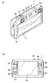
図1は、本発明に係る複眼撮像装置である複眼デジタルカメラ1の概略図であり、(a)は正面図であり、(b)は背面図である。複眼デジタルカメラ1は、複数(図1では2個を例示)の撮像系を備えた複眼デジタルカメラ1であって、同一被写体を複数視点(図1では左右二つの視点を例示)からみた立体画像や、単視点画像(2次元画像)が撮影可能である。また、複眼デジタルカメラ1は、静止画に限らず、動画、音声の記録再生も可能である。
<First Embodiment>
1A and 1B are schematic views of a compound-eye
複眼デジタルカメラ1のカメラボディ10は、略直方体の箱状に形成されており、その正面には、図1(a)に示すように、主として、バリア11、右撮像系12、左撮像系13、フラッシュ14、マイク15が設けられている。また、カメラボディ10の上面には、主として、レリーズスイッチ20、ズームボタン21が設けられている。
The
一方、カメラボディ10の背面には、図1(b)に示すように、モニタ16、モードボタン22、視差調整ボタン23、2D/3D切り替えボタン24、MENU/OKボタン25、十字ボタン26、DISP/BACKボタン27が設けられている。
On the other hand, on the back of the
バリア11は、カメラボディ10の前面に摺動可能に装着され、バリア11が上下に摺動することにより開状態と閉状態とが切り替えられる。通常は、図1(a)点線に示すように、バリア11は上端、すなわち閉状態に位置されており、対物レンズ12a、13a等はバリア11によって覆われている。これにより、レンズなどの破損が防止される。バリア11が摺動されることにより、バリアが下端、すなわち開状態に位置される(図1(a)実線参照)と、カメラボディ10前面に配設されたレンズ等が露呈される。図示しないセンサによりバリア11が開状態であることが認識されると、CPU110(図2参照)により電源がONされ、撮影が可能となる。
The
右目用の画像を撮影する右撮像系12及び左目用の画像を撮影する左撮像系13は、屈曲光学系を有する撮影レンズ群と絞り兼用メカシャッタ12d、13d(図2参照)とを含む光学ユニットである。右撮像系12及び左撮像系13の撮影レンズ群は、主として、被写体からの光を取り込む対物レンズ12a、13a、対物レンズから入射した光路を略垂直に折り曲げるプリズム(図示せず)、ズームレンズ12c、13c(図2参照)、フォーカスレンズ12b、13b(図2参照)等で構成される。
The
フラッシュ14は、キセノン管で構成されており、暗い被写体を撮影する場合や逆光時などに必要に応じて発光される。
The
モニタ16は、4:3の一般的なアスペクト比を有するカラー表示が可能な液晶モニタであり、立体画像と平面画像の両方が表示可能である。モニタ16の詳細な構造は図示しないが、モニタ16は、その表面にパララックスバリア表示層を備えたパララックスバリア式3Dモニタである。モニタ16は、各種設定操作を行なう際の使用者インターフェース表示パネルとして利用され、画像撮影時には電子ビューファインダとして利用される。
The
モニタ16は、立体画像を表示するモード(3Dモード)と、平面画像を表示するモード(2Dモード)とが切り替えが可能である。3Dモードにおいては、モニタ16のパララックスバリア表示層に光透過部と光遮蔽部とが交互に所定のピッチで並んだパターンからなるパララックスバリアを発生させるとともに、その下層の画像表示面に左右の像を示す短冊状の画像断片を交互に配列して表示する。2Dモードや使用者インターフェース表示パネルとして利用される場合には、パララックスバリア表示層には何も表示せず、その下層の画像表示面に1枚の画像をそのまま表示する。
The
なお、モニタ16は、パララックスバリア式には限定されず、レンチキュラー方式、マイクロレンズアレイシートを用いるインテグラルフォトグラフィ方式、干渉現象を用いるホログラフィー方式などが採用されてもよい。また、モニタ16は液晶モニタに限定されず、有機ELなどが採用されてもよい。
The
レリーズスイッチ20は、いわゆる「半押し」と「全押し」とからなる二段ストローク式のスイッチで構成されている。複眼デジタルカメラ1は、静止画撮影時(例えば、モードボタン22で静止画撮影モード選択時、又はメニューから静止画撮影モード選択時)、このレリーズスイッチ20を半押しすると撮影準備処理、すなわち、AE(Automatic Exposure:自動露出)、AF(Auto Focus:自動焦点合わせ)、AWB(Automatic White Balance:自動ホワイトバランス)の各処理を行い、全押しすると、画像の撮影・記録処理を行う。また、動画撮影時(例えば、モードボタン24で動画撮影モード選択時、又はメニューから動画撮影モード選択時)、このレリーズスイッチ20を全押しすると、動画の撮影を開始し、再度全押しすると、撮影を終了する。
The
ズームボタン21は、右撮像系12及び左撮像系13のズーム操作に用いられ、望遠側へのズームを指示するズームテレボタン21Tと、広角側へのズームを指示するズームワイドボタン21Wとで構成されている。
The
モードボタン22は、デジタルカメラ1の撮影モードを設定する撮影モード設定手段として機能し、このモードボタン22の設定位置により、デジタルカメラ1の撮影モードが様々なモードに設定される。撮影モードは、動画撮影を行う「動画撮影モード」と、静止画撮影を行う「静止画撮影モード」とに分けられ、「静止画撮影モード」は例えば、絞り、シャッタスピード等がデジタルカメラ1によって自動的に設定される「オート撮影モード」、人物の顔を抽出して撮影を行う「顔抽出撮影モード」、動体撮影に適した「スポーツ撮影モード」、風景の撮影に適した「風景撮影モード」、夕景及び夜景の撮影に適した「夜景撮影モード」、絞りの目盛りを使用者が設定し、シャッタスピードをデジタルカメラ1が自動的に設定する「絞り優先撮影モード」、シャッタスピードを使用者が設定し、絞りの目盛りをデジタルカメラ1が自動的に設定する「シャッタスピード優先撮影モード」、絞り、シャッタスピード等を使用者が設定する「マニュアル撮影モード」等がある。
The
視差調整ボタン23は、立体画像撮影時に視差を電子的に調整するボタンである。視差調整ボタン23の上側を押下することにより、右撮像系12で撮影された画像と左撮像系13で撮影された画像との視差が所定の距離だけ大きくなり、視差調整ボタン23の下側を押下することにより、右撮像系12で撮影された画像と左撮像系13で撮影された画像との視差が所定の距離だけ小さくなる。
The
2D/3D切り替えボタン24は、単視点画像を撮影する2D撮影モードと、多視点画像を撮影する3D撮影モードの切り替えを指示するためのスイッチである。
The 2D /
MENU/OKボタン25は、撮影及び再生機能の各種設定画面(メニュー画面)の呼び出し(MENU機能)に用いられるとともに、選択内容の確定、処理の実行指示等(OK機能)に用いられ、複眼デジタルカメラ1が持つ全ての調整項目の設定が行われる。撮影時にMENU/OKボタン25が押されると、モニタ16にたとえば露出値、色合い、ISO感度、記録画素数などの画質調整などの設定画面が表示され、再生時にMENU/OKボタン25が押されると、モニタ16に画像の消去などの設定画面が表示される。複眼デジタルカメラ1は、このメニュー画面で設定された条件に応じて動作する。
The MENU /
十字ボタン26は、各種のメニューの設定や選択あるいはズームを行うためのボタンであり、上下左右4方向に押圧操作可能に設けられており、各方向のボタンには、カメラの設定状態に応じた機能が割り当てられる。たとえば、撮影時には、左ボタンにマクロ機能のON/OFFを切り替える機能が割り当てられ、右ボタンにフラッシュモードを切り替える機能が割り当てられる。また、上ボタンにモニタ16の明るさを替える機能が割り当てられ、下ボタンにセルフタイマのON/OFFや時間を切り替える機能が割り当てられる。また、再生時には、右ボタンにコマ送りの機能が割り当てられ、左ボタンにコマ戻しの機能が割り当てられる。また、上ボタンに再生中の画像を削除する機能が割り当てられる。また、各種設定時には、モニタ16に表示されたカーソルを各ボタンの方向に移動させる機能が割り当てられる。
The
DISP/BACKボタン27は、モニタ16の表示切り替えを指示するボタンとして機能し、撮影中、このDISP/BACKボタン27が押されると、モニタ16の表示が、ON→フレーミングガイド表示→OFFに切り替えられる。また、再生中、このDISP/BACKボタン27が押されると、通常再生→文字表示なし再生→マルチ再生に切り替えられる。また、DISP/BACKボタン27は、入力操作のキャンセルや一つ前の操作状態に戻すことを指示するボタンとして機能する。
The DISP /
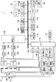
図2は、複眼デジタルカメラ1の主要な内部構成を示すブロック図である。複眼デジタルカメラ1は、主として、CPU110、操作手段(レリーズボタン20、MENU/OKボタン25、十字ボタン26等)112、SDRAM114、VRAM116、AF検出手段118、AE/AWB検出手段120、撮像素子122、123、CDS/AMP124、125、A/D変換器126、127、画像入力コントローラ128、画像信号処理手段130、立体画像信号処理部133、圧縮伸張処理手段132、ビデオエンコーダ134、メディアコントローラ136、音入力処理部138、記録メディア140、フォーカスレンズ駆動部142、143、ズームレンズ駆動部144、145、絞り駆動部146、147、タイミングジェネレータ(TG)148、149とで構成される。
FIG. 2 is a block diagram showing the main internal configuration of the compound-eye
CPU110は、複眼デジタルカメラ1の全体の動作を統括的に制御する。CPU110は、右撮像系12と左撮像系13の動作を制御する。右撮像系12と左撮像系13とは、基本的に連動して動作を行うが、各々個別に動作させることも可能である。また、CPU110は、右撮像系12及び左撮像系13で得られた2つの画像データを短冊状の画像断片とし、これがモニタ16に交互に表示されるような表示用画像データを生成する。3Dモードで表示を行う際に、パララックスバリア表示層に光透過部と光遮蔽部とが交互に所定のピッチで並んだパターンからなるパララックスバリアを発生させるとともに、その下層の画像表示面に左右の像を示す短冊状の画像断片を交互に配列して表示することで立体視を可能にする。
The
SDRAM114には、このCPU110が実行する制御プログラムであるファームウェア、制御に必要な各種データ、カメラ設定値、撮影された画像データ等が記録されている。
The
VRAM116は、CPU110の作業用領域として利用されるとともに、画像データの一時記憶領域として利用される。
The
AF検出手段118は、CPU110からの指令に従い、入力された画像信号からAF制御に必要な物理量を算出する。AF検出手段118は、右撮像系12から入力された画像信号に基づいてAF制御を行う右撮像系AF制御回路と、左撮像系13から入力された画像信号に基づいてAF制御を行う左撮像系AF制御回路とで構成される。本実施の形態のデジタルカメラ1では、撮像素子122、123から得られる画像のコントラストによりAF制御が行われ(いわゆるコントラストAF)、AF検出手段118は、入力された画像信号から画像の鮮鋭度を示す焦点評価値を算出する。CPU110は、このAF検出手段118で算出される焦点評価値が極大となる位置を検出し、その位置にフォーカスレンズ群を移動させる。すなわち、フォーカスレンズ群を至近から無限遠まで所定のステップで移動させ、各位置で焦点評価値を取得し、得られた焦点評価値が最大の位置を合焦位置として、その位置にフォーカスレンズ群を移動させる。
The
AE/AWB検出回路120は、CPU110からの指令に従い、入力された画像信号からAE制御及びAWB制御に必要な物理量を算出する。たとえば、AE制御に必要な物理量として、1画面を複数のエリア(たとえば16×16)に分割し、分割したエリアごとにR、G、Bの画像信号の積算値を算出する。CPU110は、このAE/AWB検出回路120から得た積算値に基づいて被写体の明るさ(被写体輝度)を検出し、撮影に適した露出値(撮影EV値)を算出する。そして、算出した撮影EV値と所定のプログラム線図から絞り値とシャッタスピードを決定する。また、AWB制御に必要な物理量として、1画面を複数のエリア(例えば、16×16)に分割し、分割したエリアごとにR、G、Bの画像信号の色別の平均積算値を算出する。CPU110は、得られたRの積算値、Bの積算値、Gの積算値から分割エリアごとにR/G及びB/Gの比を求め、求めたR/G、B/Gの値のR/G、B/Gの色空間における分布等に基づいて光源種判別を行う。そして、判別された光源種に適したホワイトバランス調整値に従って、たとえば各比の値がおよそ1(つまり、1画面においてRGBの積算比率がR:G:B≒1:1:1)になるように、ホワイトバランス調整回路のR、G、B信号に対するゲイン値(ホワイトバランス補正値)を決定する。
The AE /
撮像素子122、123は、所定のカラーフィルタ配列(例えば、ハニカム配列、ベイヤ配列)のR、G、Bのカラーフィルタが設けられたカラーCCDで構成されている。撮像素子122、123は、フォーカスレンズ12b、13b、ズームレンズ12c、13c等によって結像された被写体光を受光し、この受光面に入射した光は、その受光面に配列された各フォトダイオードによって入射光量に応じた量の信号電荷に変換される。撮像素子122、123の光電荷蓄積・転送動作は、TG148、149からそれぞれ入力される電荷排出パルスに基づいて電子シャッタ速度(光電荷蓄積時間)が決定される。
The
すなわち、撮像素子122、123に電荷排出パルスが入力されている場合には、撮像素子122、123に電荷が蓄えられることなく排出される。それに対し、撮像素子122、123に電荷排出パルスが入力されなくなると、電荷が排出されなくなるため、撮像素子122、123において電荷蓄積、すなわち露光が開始される。撮像素子122、123で取得された撮像信号は、TG148、149からそれぞれ与えられる駆動パルスに基づいてCDS/AMP124、125に出力される。
That is, when a charge discharge pulse is input to the
CDS/AMP124、125は、撮像素子122、123から出力された画像信号に対して相関二重サンプリング処理(撮像素子の出力信号に含まれるノイズ(特に熱雑音)等を軽減することを目的として、撮像素子の1画素毎の出力信号に含まれるフィードスルー成分レベルと画素信号成分レベルとの差をとることにより正確な画素データを得る処理)を行い、増幅してR、G、Bのアナログの画像信号を生成する。
The CDS /
A/D変換器126、127は、CDS/AMP124、125で生成されたR、G、Bのアナログの画像信号デジタルの画像信号に変換する。
The A /
画像入力コントローラ128は、所定容量のラインバッファを内蔵しており、CPU110からの指令に従い、CDS/AMP/AD変換部から出力された1画像分の画像信号を蓄積して、VRAM116に記録する。
The
画像信号処理手段130は、同時化回路(単板CCDのカラーフィルタ配列に伴う色信号の空間的なズレを補間して色信号を同時式に変換する処理回路)、ホワイトバランス補正回路、ガンマ補正回路、輪郭補正回路、輝度・色差信号生成回路等を含み、CPU110からの指令に従い、入力された画像信号に所要の信号処理を施して、輝度データ(Yデータ)と色差データ(Cr,Cbデータ)とからなる画像データ(YUVデータ)を生成する。
The image
圧縮伸張処理手段132は、CPU110からの指令に従い、入力された画像データに所定形式の圧縮処理を施し、圧縮画像データを生成する。また、CPU110からの指令に従い、入力された圧縮画像データに所定形式の伸張処理を施し、非圧縮の画像データを生成する。
The compression /
ビデオエンコーダ134は、モニタ16への表示を制御する。すなわち、記録メディア140などに保存された画像信号をモニタ16に表示するための映像信号(たとえば、NTSC信号やPAL信号、SCAM信号)に変換してモニタ16に出力するとともに、必要に応じて所定の文字、図形情報をモニタ16に出力する。
The
メディアコントローラ136は、圧縮伸張処理手段132で圧縮処理された各画像データを記録メディア140に記録する。
The
音入力処理部138は、マイク15に入力され、図示しないステレオマイクアンプで増幅された音声信号が入力され、この音声信号の符号化処理を行う。
The sound
記録メディア140は、複眼デジタルカメラ1に着脱自在なxDピクチャカード(登録商標)、スマートメディア(登録商標)に代表される半導体メモリカード、可搬型小型ハードディスク、磁気ディスク、光ディスク、光磁気ディスク等、種々の記録媒体である。
The
フォーカスレンズ駆動部142、143は、CPU110からの指令に従い、フォーカスレンズ12b、13bをそれぞれ光軸方向に移動させ、焦点位置を可変する。
The focus
ズームレンズ駆動部144、145は、CPU110からの指令に従い、ズームレンズ12c、13cそれぞれ光軸方向に移動させ、焦点距離を可変する。
The zoom
絞り兼用メカシャッタ12d、13dは、それぞれ絞り駆動部146、147のアイリスモータに駆動されることにより、その開口量を可変して、撮像素子122、123への入射光量を調整する。
The aperture /
絞り駆動部146、147は、CPU110からの指令に従い、絞り兼用メカシャッタ12d、13dの開口量を可変して、撮像素子122、123への入射光量をそれぞれ調整する。また、絞り駆動部146、147は、CPU110からの指令に従い、絞り兼用メカシャッタ12d、13dを開閉して、撮像素子122、123への露光/遮光それぞれを行う。
The
以上のように構成された複眼デジタルカメラ1の作用について説明する。バリア11を閉状態から開状態へと摺動させると、複眼デジタルカメラ1の電源が投入され、複眼デジタルカメラ1は、撮影モードの下で起動する。撮影モードとしては、2Dモードと、同一被写体を2視点からみた立体画像を撮影する3D撮影モードとが設定可能である。また、2Dモードとしては、右撮像系12又は左撮像系13のみを用いて平面画像を撮影する通常2D撮影モード、広い範囲の画像(ワイド側の画像)と、被写体を大きくズームアップした画像(テレ側の画像)との2枚の2次元画像を撮影するテレ/ワイド同時撮りモード等が設定可能である。撮影モードの設定は、複眼デジタルカメラ1が撮影モードで駆動中にMENU/OKボタン25が押下されることによりモニタ16に表示されるメニュー画面から設定可能である。
The operation of the compound eye
(1)通常2D撮影モード
CPU110は、右撮像系12又は左撮像系13(本実施の形態では左撮像系13)を選択し、左撮像系13の撮像素子123によってライブビュー画像用の撮影を開始する。すなわち、撮像素子123で連続的に画像が撮像され、その画像信号が連続的に処理されて、ライブビュー画像用の画像データが生成される。
(1) Normal 2D shooting mode The
CPU110は、モニタ16を2Dモードとし、生成された画像データを順次ビデオエンコーダ134に加え、表示用の信号形式に変換してモニタ16に出力する。これにより、撮像素子123で捉えた画像がモニタ16にスルー表示される。モニタ16の入力がデジタル信号に対応している場合にはビデオエンコーダ134は不要であるが、モニタ16の入力仕様に合致した信号形態に変換する必要がある。
The
ユーザ(使用者)は、モニタ16に表示されるスルー画像を見ながらフレーミングしたり、撮影したい被写体を確認したり、撮影後の画像を確認したり、撮影条件を設定したりする。
A user (user) performs framing while viewing a through image displayed on the
上記撮影スタンバイ状態時にレリーズスイッチ20が半押しされると、CPU110にS1ON信号が入力される。CPU110はこれを検知し、AE測光、AF制御を行う。AE測光時には、撮像素子123を介して取り込まれる画像信号の積算値等に基づいて被写体の明るさを測光する。この測光した値(測光値)は、本撮影時における絞り兼用メカシャッタ13dの絞り値、及びシャッタ速度の決定に使用される。同時に、検出された被写体輝度より、フラッシュ14の発光が必要かどうかを判断する。フラッシュ14の発光が必要と判断された場合には、フラッシュ14をプリ発光させ、その反射光に基づいて本撮影時のフラッシュ14の発光量を決定する。
When the
レリーズスイッチ20が全押しされると、CPU110にS2ON信号が入力される。CPU110は、このS2ON信号に応動して、撮影、記録処理を実行する。
When the
まず、CPU110は、前記測光値に基づいて決定した絞り値に基づいて絞り駆動部147を介して絞り兼用メカシャッタ13dを駆動するとともに、前記測光値に基づいて決定したシャッタ速度になるように撮像素子123での電荷蓄積時間(いわゆる電子シャッタ)を制御する。
First, the
また、CPU110は、AF制御時にはフォーカスレンズを至近から無限遠に対応するレンズ位置に順次移動させるとともに、レンズ位置毎に撮像素子123を介して取り込まれた画像のAFエリアの画像信号に基づいて画像信号の高周波成分を積算した評価値をAF検出手段118から取得し、この評価値がピークとなるレンズ位置を求め、そのレンズ位置にフォーカスレンズを移動させるコントラストAFを行う。
Further, the
この際、フラッシュ14を発光させる場合は、プリ発光の結果から求めたフラッシュ14の発光量に基づいてフラッシュ14を発光させる。
At this time, when the
被写体光は、フォーカスレンズ13b、ズームレンズ13c、絞り兼用メカシャッタ13d、赤外線カットフィルタ46、及び光学ローパスフィルタ48等を介して撮像素子123の受光面に入射する。
Subject light is incident on the light receiving surface of the
撮像素子123の各フォトダイオードに蓄積された信号電荷は、TG149から加えられるタイミング信号に従って読み出され、電圧信号(画像信号)として撮像素子123から順次出力され、CDS/AMP125に入力される。
The signal charges accumulated in each photodiode of the
CDS/AMP125は、CDSパルスに基づいてCCD出力信号を相関二重サンプリング処理し、CPU110から加えられる撮影感度設定用ゲインによってCDS回路から出力される画像信号を増幅する。
The CDS /
CDS/AMP125から出力されたアナログの画像信号は、A/D変換器127において、デジタルの画像信号に変換され、この変換された画像信号(R、G、BのRAWデータ)は、SDRAM114に転送され、ここに一旦蓄えられる。
The analog image signal output from the CDS /
SDRAM114から読み出されたR、G、Bの画像信号は、画像信号処理手段130に入力される。画像信号処理手段130では、ホワイトバランス調整回路によりR、G、Bの画像信号ごとにデジタルゲインをかけることでホワイトバランス調整が行われ、ガンマ補正回路によりガンマ特性に応じた階調変換処理が行われ、単板CCDのカラーフィルタ配列に伴う各色信号の空間的なズレを補間して色信号の位相を合わせる同時化処理が行われる。同時化されたR、G、Bの画像信号は、更に輝度・色差データ生成回路により輝度信号Yと色差信号Cr、Cb(YC信号)に変換され、Y信号は、輪郭補正回路により輪郭強調処理される。画像信号処理手段130で処理されたYC信号は再びSDRAM114に蓄えられる。
The R, G, and B image signals read from the
上記のようにしてSDRAM114に蓄えられたYC信号は、圧縮伸張処理手段132によって圧縮され、所定のフォーマットの画像ファイルとして、メディアコントローラ136を介して記録メディア140に記録される。静止画のデータは、Exif規格に従った画像ファイルとして記録メディア140に格納される。Exifファイルは、主画像のデータを格納する領域と、縮小画像(サムネイル画像)のデータを格納する領域とを有している。撮影によって取得された主画像のデータから画素の間引き処理その他の必要なデータ処理を経て、規定サイズ(例えば、160×120又は80×60ピクセルなど)のサムネイル画像が生成される。こうして生成されたサムネイル画像は、主画像とともにExifファイル内に書き込まれる。また、Exifファイルには、撮影日時、撮影条件、顔検出情報等のタグ情報が付属されている。
The YC signal stored in the
通常2D撮影モードから他の撮影モードへの切り替え(撮影モードの遷移)が入力された場合には、CPU110は、遷移先の撮影モードがテレ/ワイド同時撮りモードか3D撮影モードかを判断する。CPU110は、遷移先の撮影モードがテレ/ワイド同時撮りモードである場合には、モニタ16を2Dモードのままに他の撮影モードの処理を開始し、遷移先の撮影モードが3Dモードである場合には、モニタ16を3Dモードに切り替え、他の撮影モードの処理を開始する。
When switching from the normal 2D shooting mode to another shooting mode (shooting mode transition) is input, the
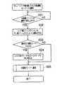
(2)テレ/ワイド同時撮りモード
図3は、テレ/ワイド同時撮りモードにおける撮影処理の流れを示すフローチャートである。以下、右撮像系12でワイド側の画像を撮影し、左撮像系13でテレ側の画像を撮影するとして説明する。右撮像系12でテレ側の画像を撮影し、左撮像系13でワイド側の画像を撮影してもよいことはいうまでもない。
(2) Tele / Wide Simultaneous Shooting Mode FIG. 3 is a flowchart showing the flow of shooting processing in the tele / wide simultaneous shooting mode. In the following description, it is assumed that the
テレ/ワイド同時撮りモードに設定されると、右撮像系12及び左撮像系13でライブビュー画像用の撮影を開始する。すなわち、撮像素子122、123で連続的に画像が撮像され、連続的に処理されて、ライブビュー画像用の画像データが生成される。撮像素子122、123の撮影範囲(ズーム画角)が異なる場合には、ズーム画角の差異によって右撮像系12及び左撮像系13のレンズの明るさが変わってしまう。また、ズームの画角が異なる場合には、撮像素子122、123が撮影している被写体が異なるため、一回のフラッシュ発光で2つの被写体に対して適正にフラッシュ調光することは困難である。そのため、CPU110は、テレ/ワイド同時撮りモードに設定された場合には、フラッシュ14の発光を禁止するようにしてもよい。これにより、フラッシュを照射することにより、被写体が明るくなりすぎ、白とびが発生する等の問題が発生することを防止することができる。
When the tele / wide simultaneous shooting mode is set, shooting for the live view image is started by the
CPU110は、モニタ16が2Dモードか否かを判断する(ステップS1)。2Dモードである場合(ステップS1でYES)には、CPU110は、左撮像系13で撮影されたライブビュー画像用の画像データをビデオエンコーダ134を介してモニタ16に出力する(ステップS2)。2Dモードで無い場合(ステップS1でNO)には、CPU110は、モニタ16を3Dモードから2Dモードに切り替え、左撮像系13で撮影されたライブビュー画像用の画像データをビデオエンコーダ134を介してモニタ16に出力する(ステップS3)。これにより、左撮像系13で撮影されたテレ側のスルー画像がモニタ16に全画面表示される。したがって、画像が誤って立体表示される等により、使用者が3D撮影モードであると誤解することを防止することができる。
CPU110は、右撮像系12及び左撮像系13のズーム位置がワイド端であるか否かを判断する(ステップS4)。右撮像系12及び左撮像系13のズーム位置がワイド端である場合(ステップS4でYES)には、CPU110は、テレ側の画像を撮影する左撮像系13のズーム位置を、ズームレンズ駆動部145を介して一段テレ側に移動させる(ステップS5)。右撮像系12及び左撮像系13のズーム位置がワイド端でない場合(ステップS4でNO)には、CPU110は、ワイド用の画像を撮影する右撮像系12のズーム位置を、ズームレンズ駆動部144を介してワイド端に移動させる(ステップS6)。これにより、右撮像系12のズームレンズ12cと左撮像系13のズームレンズ13cとのズームポジションを異ならせ、撮影範囲の異なる2枚の画像が撮影可能となる。本実施の形態では、ズームレンズ12cはワイド端に位置し、ズームレンズ13cはワイド端より少なくとも1段テレ側に位置する。
The
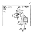
CPU110は、ステップS5、S6が行われた後のズームレンズ12c及びズームレンズ13cの位置に基づいてガイダンス30(図4参照)を生成する。ガイダンス30は、ワイド用の画像の撮影範囲を示す枠30aと、テレ用の画像の撮影範囲を示す枠30bとを、中心が一致するように重ねた図形である。CPU110は、生成したガイダンス30を、ビデオエンコーダ134を介してモニタ16に出力する(ステップS7)。
The
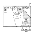
これにより、図4に示すように、テレ側のスルー画像にガイダンス30が重ねて表示される。したがって、使用者が複数の平面画像の撮影範囲をひと目で認識し、テレ側の画像としてどのような画像が撮影されるかに加え、ワイド側の画像としてどのような画像が撮影されるかを知ることができる。また、ワイド用の画像の撮影範囲を示す枠30aと、テレ用の画像の撮影範囲を示す枠30bとを、中心が一致するように重ねた図形をガイダンスとして出力することで、使用者は、テレ側の画像の撮影範囲とワイド側の画像の撮影範囲との比をひと目で認識することができる。さらに、テレ側のスルー画像がモニタ16全面に表示されているため、使用者はテレ側の画像を見ることにより、被写体の細かい部分まで認知することができる。
Thereby, as shown in FIG. 4, the
また、図4に示すように、テレ/ワイド同時撮りモードを示すアイコンがモニタ16の左上に表示される。したがって、撮影範囲の異なる2枚の平面画像(テレ側、ワイド側の画像)を撮影していることを使用者が認識することができる。更に、モニタ16の略中央には、静止画の撮影であることを示すターゲットマークが表示される。
As shown in FIG. 4, an icon indicating the tele / wide simultaneous shooting mode is displayed on the upper left of the
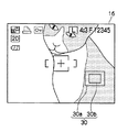
CPU110は、使用者によりズームボタン21が操作されたか否かを判断する(ステップS8)。ズームボタン21が操作された場合(ステップS8でYES)には、CPU110は、ズームボタン21に操作に応じて、ズームレンズ駆動部145を介して左撮像系13のズームレンズ13cのズームポジションを移動させ、ビデオエンコーダ134を介して左撮像系13で撮影されたライブビュー画像用の画像データをモニタ16に出力する。これにより、モニタ16に表示されるスルー画像が更新される。また、CPU110は、移動後のズームポジションに基づいてガイダンス30を更新する。
The
例えば、ズームポジションを2段テレ側に移動させることを示す指示がズームボタン21の操作により入力された場合には、図5に示すように、ズームポジションが2段テレ側に移動した後のスルー画像がモニタ16に表示されるとともに、ガイダンス30のテレ用の画像の撮影範囲を示す枠30bが小さくなる。このように、モニタ16の表示がテレ側のスルー画像表示となった後でズームポジションの移動を行うことで、ズームポジションの変更と表示とを連動させ、ズーム操作時に使用者が違和感を覚えることなく、操作性を向上させることができる。
For example, when an instruction indicating that the zoom position is to be moved to the second-stage telephoto side is input by operating the
ズームボタン21が操作されていない場合(ステップS8でNO)には、CPU110は、レリーズスイッチ20が半押しされたか否か、すなわちCPU110にS1ON信号が入力されか否かを判断する(ステップS10)。レリーズスイッチ20が半押しされていない場合(ステップS10でNO)には、再度ステップS10が行われる。レリーズスイッチ20が半押しされた場合(ステップS10でYES)には、CPU110は右撮像系12及び左撮像系13のそれぞれについてAE測光、AF制御を行う(ステップS11)。AE測光、AF制御は、通常2D撮影モードと同じであるため、詳細な説明は省略する。CPU110は、一度合焦状態になった場合には、フォーカスレンズ12b、13bのレンズ駆動を停止させてフォーカスロックを行う。そして、CPU110は、図6に示すように、合焦状態におけるテレ側の画像をモニタ16に全画面表示させる。
If the
CPU110は、レリーズスイッチ20が全押しされたか否か、すなわちCPU110にS2ON信号が入力されか否かを判断する(ステップS12)。レリーズスイッチ20が全押しされていない場合(ステップS12でNO)には、再度ステップS12が行われる。レリーズスイッチ20が全押しされた場合(ステップS12でYES)には、CPU110は、撮像素子122、123の各フォトダイオードに蓄積された信号電荷を取得して画像データを生成する(ステップS13)。ステップS13の処理については、通常2D撮影モードと同一であるため、説明を省略する。本実施の形態では、1度のS2ON信号入力によりテレ側の画像とワイド側の画像との画像データが取得されればよく、テレ側の画像とワイド側の画像とが同時に露光、処理されるようにしてもよいし、順次露光、処理されるようにしてもよい。
The
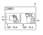
CPU110は、図7に示すように、ステップS13で撮影されたワイド側の画像31と、テレ側の画像32とを同じ大きさで並べた画像を生成し、その画像をいわゆるポストビューとしてモニタ16に表示する(ステップS14)。これにより、撮影されたワイド側の画像と、テレ側の画像とを撮影後、記録前に確認することができる。
As shown in FIG. 7, the
図8は、テレ/ワイド同時撮りモードで撮影された画像の記録処理の流れを示すフローチャートである。複眼デジタルカメラ1が撮影モードで駆動中にMENU/OKボタン25が押下されることによりモニタ16に表示されるメニュー画面から、記録処理に関する設定が可能である。本実施の形態では、記録前に画像を選択するか否かを設定可能である。
FIG. 8 is a flowchart showing the flow of recording processing of an image shot in the tele / wide simultaneous shooting mode. Settings relating to the recording process can be made from the menu screen displayed on the
CPU110は、記録処理に関して設定がされているか否かを判断する(ステップS20)。設定がされていない場合(ステップS20でNO)には、ワイド側の画像及びテレ側の画像を自動的に記録する(ステップS21)。
The
設定が記録されている場合(ステップS20でYES)には、CPU110は、モニタ16に画像の選択を誘導する表示を行い(ステップS22)、画像の選択が入力されたか否かを判断する(ステップS23)。画像の選択は、図示しない選択画面において操作部112を用いて画像を選択することにより行われる。画像の選択が入力されていない(ステップS23でNO)場合には、再度ステップS23が行われる。画像の選択が入力された場合(ステップS23でYES)には、選択が入力された画像を記録する(ステップS24)。
When the setting is recorded (YES in step S20),
これにより、使用者の選択により、画像を自動的に記録するか、希望する画像のみを記録するかを選択することができ、使用者の使い勝手が良くなる。なお、画像の記録処理は、通常2D撮影モードと同様の方法であるため、説明を省略する。 Accordingly, it is possible to select whether to automatically record an image or only a desired image according to the user's selection, and the user's convenience is improved. Note that the image recording process is the same method as in the normal 2D shooting mode, and a description thereof will be omitted.
図9は、テレ/ワイド同時撮りモードから他の撮影モードへの切り替え時の処理の流れを示すフローチャートである。 FIG. 9 is a flowchart showing the flow of processing when switching from the tele / wide simultaneous shooting mode to another shooting mode.
CPU110は、MENU/OKボタン25等が操作されることにより他の撮影モード(通常2D撮影モード、3D撮影モード等)に設定が変更されたか(他撮影モードへの遷移が発生したか)否かを判断する(ステップS31)。他撮影モードへの遷移が発生していない場合(ステップS31でNO)には、再度ステップS31が行われる。
Whether the setting has been changed to another shooting mode (normal 2D shooting mode, 3D shooting mode, etc.) by operating the MENU /
他撮影モードへの遷移が発生した場合(ステップS31でYES)には、CPU110は、ズームレンズ駆動部144を介して、ワイド側の画像を撮影する右撮像系12のズームポジションを、テレ側の画像を撮影する左撮像系13のズームポジションへ移動させる(ステップS32)。右撮像系12と左撮像系13のズームポジションが異なる撮影モードはテレ/ワイド同時撮りモードのみであるため、今後の処理のためには、遷移後の撮影モードが何であれ、右撮像系12と左撮像系13のズームポジションは揃えておく必要がある。しかしながら、スルー画像としてモニタ16に表示されているのはテレ側の画像であるため、左撮像系13のズームポジションを移動させると、モニタ16の表示が変わり、使用者が違和感を覚えることとなる。したがって、右撮像系12のズームポジションを移動させることにより、このような不具合を防止することができる。
When the transition to the other shooting mode occurs (YES in step S31), the
CPU110は、遷移先の撮影モードが3D撮影モードか否かを判断する(ステップS33)。遷移先の撮影モードが3D撮影モードである場合(ステップS33でYES)には、CPU110は、モニタ16を3Dモードに切り替え(ステップS34)、他の撮影モードの処理を開始する(ステップS35)。遷移先の撮影モードが3D撮影モードでない場合(ステップS34でNO)には、モニタ16は2Dモードのまま他の撮影モードの処理を開始する(ステップS35)。
The
(3)3D撮影モードに設定されている場合
撮像素子122及び撮像素子123によってライブビュー画像用の撮影を開始する。すなわち、撮像素子122及び撮像素子123で同じ被写体が連続的に撮像され、その画像信号が連続的に処理され、ライブビュー画像用の立体画像データが生成される。CPU110は、モニタ16を3Dモードに設定し、生成された画像データはビデオエンコーダ134で順次表示用の信号形式に変換されて、それぞれモニタ16に出力される。
(3) When set to 3D shooting mode Shooting for live view images is started by the
生成された画像データは、順次ビデオエンコーダ134に加えられ、表示用の信号形式に変換されて、モニタ16に出力される。これにより、ライブビュー画像用の立体画像データがモニタ16にスルー表示される。
The generated image data is sequentially added to the
ユーザ(使用者)は、モニタ16に表示されるスルー画像を見ながらフレーミングしたり、撮影したい被写体を確認したり、撮影後の画像を確認したり、撮影条件を設定したりする。
A user (user) performs framing while viewing a through image displayed on the
上記撮影スタンバイ状態時にレリーズスイッチ20が半押しされると、CPU110にS1ON信号が入力される。CPU110はこれを検知し、AE測光、AF制御を行う。AE測光は、右撮像系12又は左撮像系13(本実施の形態では左撮像系13)の一方で行う。また、AF制御は、右撮像系12及び左撮像系13のそれぞれで行う。AE測光、AF制御は通常2D撮影モードと同一であるため、詳細な説明を省略する。
When the
レリーズスイッチ20が全押しされると、CPU110にS2ON信号が入力される。CPU110は、このS2ON信号に応動して、撮影、記録処理を実行する。右撮像系12及び左撮像系13のそれぞれで撮影された画像データを生成する処理については、通常2D撮影モードと同一であるため、説明を省略する。
When the
CDS/AMP124、125でそれぞれ生成された2枚の画像データからは、通常2D撮影モードと同様の方法により、圧縮画像データが2個生成される。圧縮された2枚の画像データは、関連付けされた状態で記憶メディア137に記録される。
Two pieces of compressed image data are generated from the two pieces of image data respectively generated by the CDS /
3D撮影モードから他の撮影モードへの切り替えが入力された場合には、遷移先の撮影モードが通常2D撮影モードか、テレ/ワイド同時撮りモードであるため、CPU110は、モニタ16を2Dモードに切り替え、他の撮影モードの処理を開始する。
When switching from the 3D shooting mode to another shooting mode is input, since the shooting mode at the transition destination is the normal 2D shooting mode or the tele / wide simultaneous shooting mode, the
複眼デジタルカメラ1のモードを再生モードに設定すると、CPU110は、メディアコントローラ136にコマンドを出力し、記録メディア140に最後に記録された画像ファイルを読み出させる。
When the mode of the compound-eye
読み出された画像ファイルの圧縮画像データは、圧縮・伸張回路148に加えられ、非圧縮の輝度/色差信号に伸張され、立体画像信号処理部133で立体画像とされたのち、ビデオエンコーダ134を介してモニタ16に出力される。これにより、記録メディア140に記録されている画像がモニタ16に再生表示される(1枚画像の再生)。
The compressed image data of the read image file is added to the compression /
1枚画像の再生においては、通常2D撮影モードで撮影された画像は、画像がモニタ16全面に2Dモードで表示され、テレ/ワイド同時撮りモードで撮影された画像は、図7に示すようにテレ側の画像とワイド側の画像とが並んで表示され、3Dモードで撮影された画像は、画像がモニタ16全面に3Dモードで表示される。テレ/ワイド同時撮りモードで撮影された画像については、使用者の選択により、テレ側の画像又はワイド側の画像のみをモニタ16全面に2Dモードで表示させることもできるし、テレ側の画像とガイダンス30とを表示させることもできる。
In the reproduction of a single image, an image shot in the normal 2D shooting mode is displayed in the 2D mode on the entire surface of the
画像のコマ送りは、十字ボタン26の左右のキー操作によって行なわれ、十字ボタン26の右キーが押されると、次の画像ファイルが記録メディア140から読み出され、モニタ16に再生表示される。また、十字ボタンの左キーが押されると、一つ前の画像ファイルが記録メディア140から読み出され、モニタ16に再生表示される。
Image frame advance is performed by operating the left and right keys of the
モニタ16に再生表示された画像を確認しながら、必要に応じて、記録メディア140に記録された画像を消去することができる。画像の消去は、画像がモニタ16に再生表示された状態でMENU/OKボタン25が押下されることによって行われる。
While confirming the image reproduced and displayed on the
本実施の形態によれば、立体画像のみでなく、撮影範囲の異なる複数の平面画像を撮影することができる。 According to the present embodiment, not only a stereoscopic image but also a plurality of planar images with different shooting ranges can be taken.
また、本実施の形態によれば、ガイダンスを見ることにより、テレ側の画像の撮影範囲と、ワイド側の画像の撮影範囲とを知ることがきる。また、テレ側のスルー画像がモニタ全面に表示されているため、使用者はテレ側の画像を見ることにより、被写体の細かい部分まで認知することができる。 Further, according to the present embodiment, it is possible to know the shooting range of the tele-side image and the shooting range of the wide-side image by viewing the guidance. In addition, since the through image on the tele side is displayed on the entire monitor surface, the user can recognize the detailed portion of the subject by viewing the image on the tele side.
また、本実施の形態では、画像を自動的に記録するか、希望する画像のみを記録するかを選択することができ、使用勝手を良くすることができる。 In the present embodiment, it is possible to select whether to automatically record an image or only a desired image, and to improve usability.
なお、本実施の形態では、図4に示すように、ワイド用の画像の撮影範囲を示す枠30aと、テレ用の画像の撮影範囲を示す枠30bとを、中心が一致するように重ねた図形であるガイダンス30を、テレ側のスルー画像に重ねて表示したが、ガイダンスはこの形態に限られない。
In the present embodiment, as shown in FIG. 4, a
たとえば、図10に示すように、ワイド用の画像の撮影範囲を示す枠30aと、テレ用の画像の撮影範囲を示す枠30bとに加え、テレ用の画像の最小撮影範囲、すなわちテレ端の位置における撮影範囲を示す枠30cを中心が一致するように重ねてもよい。これにより、使用者は、撮影範囲の限界(最大の範囲と最小の範囲)を認識することができる。
For example, as shown in FIG. 10, in addition to a
また、図11に示すように、テレ側の画像をモニタ16に全画面表示したうえで、ワイド用の画像の撮影範囲を示す枠30a内に、ワイド側の画像30d(スルー画像であっても、撮影開始時に撮影された画像でもよい)を縮小表示するようにしてもよい。また、ワイド用の画像の撮影範囲を示す枠30aと、テレ用の画像の撮影範囲を示す枠30bとを並列表示してもよい。これにより、使用者は、複数の平面画像のうち最も撮影範囲が広い画像としてどのような画像が撮影されたかを確認することができる。
Further, as shown in FIG. 11, after the tele-side image is displayed on the
また、本実施の形態では、スルー画像の表示としてテレ側の画像とガイダンス30とを表示させたが、テレ側の画像とガイダンス30とを表示するのはスルー画像に限定されない。例えば、S1後のフォーカスロック時に、合焦状態において撮像素子123で捉えた画像とガイダンス30とを表示するようにしてもよい。
Further, in the present embodiment, the tele-side image and the
また、動画の撮影時にテレ側の画像とガイダンス30とを表示させてもよい。スルー画像の撮影時にレリーズスイッチ20が長押しされると、CPU110は、撮像素子122、123で同フレームレートで同タイミングで画像を連続して撮影することで、右撮像系12及び左撮像系12で同時に動画を撮影する。
Further, the tele-side image and the
図12は、動画撮影時のモニタ16表示の一例である。動画撮影時には、静止画撮影時と同様にテレ/ワイド同時撮りモードであることを示すアイコンが表示されるとともに、動画撮影であることを示すアイコンがモニタ16に表示される。なお、この場合にはターゲットマークは表示されない。
FIG. 12 is an example of display on the
動画撮影時にも、スルー画像撮影時と同様に、ズーム操作に応じてテレ側の画像を撮影する左撮像系13のズームレンズ13cが移動され、それに伴いモニタ16に表示される画像も変更される(図13参照)。また、図13に示すように、ワイド用の画像の撮影範囲を示す枠30a内にワイド側の画像30dを縮小表示するようにしてもよい。
Also during moving image shooting, as in through image shooting, the zoom lens 13c of the
動画撮影時には、所定の期間だけ撮影動作が継続している。したがって、動画撮影中にモニタ16に表示する画像が切り替えられるようにすることもできる。十字ボタン26等の操作手段を介して表示画像の切り替えを示す指示が入力されると、CPU110はこれを検出し、現在表示されている画像以外の画像をモニタ16に表示する。何も操作がされていない場合には、図14(a)に示すようにモニタ16にはテレ側の画像(本実施の形態では左撮像系13で撮影された画像)が表示されている。この状態で、CPU110が画像の切り替え指示が検出すると、右撮像系12で撮影されたワイド側の画像データがビデオエンコーダ134を介してモニタ16に出力される。これにより、図14(b)に示すようにモニタ16にワイド側の画像が表示される。このように、動画撮影時モニタ16に全面表示されている(メイン表示)画像を切り替えることができ、各撮像手段で撮影されている画像を確認することができる。このメイン表示の切り替えは、スルー画像撮影時にも行なえるようにしてもよい。
During moving image shooting, the shooting operation continues for a predetermined period. Therefore, the image displayed on the
また、本実施の形態では、図7に示すように、撮影直後にいわゆるポストビューとしてワイド側の画像31と、テレ側の画像32とを同じ大きさで並べた画像をモニタ16に表示したが、ポストビューはこの形態に限られない。
In the present embodiment, as shown in FIG. 7, an image in which the
例えば、図15に示すように、ワイド側の画像31と、テレ側の画像32とを同じ大きさで並べた上で、ワイド側の画像31にテレ側の画像の撮影範囲を示す枠33を重ねて表示するようにしてもよい。また、ワイド側の画像31と、テレ側の画像32とを同じ大きさで並べる必要はないし、左右上下どの方向に並べても良い。
For example, as shown in FIG. 15, a wide-
また、いわゆるポストビューとしてテレ側の画像とガイダンス30とを表示させてもよい。動画撮影の場合にも、いわゆるポストビューとしてワイド側の画像31と、テレ側の画像32とを同じ大きさで並べた画像をモニタ16に表示してもよいし、テレ側の画像とガイダンス30とを表示してもよい。
Further, the tele-side image and the
また、本実施の形態では、いわゆるポストビューとしてワイド側の画像31と、テレ側の画像32とを同じ大きさで並べた画像をモニタ16に表示したが、ワイド側の画像とテレ側の画像を並列表示するのはポストビューに限定されない。例えば、右撮像系12で撮影されたワイド側のライブビュー画像と、左撮像系13で撮影されたテレ側のライブビュー画像を並べてスルー画像としてモニタ16に表示してもよい。また、S1後のフォーカスロック時に、合焦状態において撮像素子122で捉えた画像と撮像素子123で捉えた画像とを並べて画像をS1後に表示してもよい。また、動画撮影時に、右撮像系12で撮影されたワイド側の動画と、左撮像系13で撮影されたテレ側の動画を並べて並列表示をしてもよい。
In the present embodiment, an image in which the wide-
また、本実施の形態では、テレ/ワイド同時撮りモードの時において、スルー画像の撮影前にモニタ16を2Dモードに設定したが、図16に示すように、3D撮影モードから2D撮影モードへの撮影モードの遷移を設定する場合のメニュー画面をモニタ16全体に表示するようにしてもよい。メニュー画面は2次元表示であるため、予めモニタ16を2Dモードにするのと同様の効果が得られる。
In the present embodiment, the
<第2の実施の形態>
本発明の第1の実施の形態は、テレ/ワイド同時撮りモードに設定された時に、右撮像系12及び左撮像系13のズームポジションを決定してからモニタ16を2Dモードに設定したが、順序はこれに限られない。
<Second Embodiment>
In the first embodiment of the present invention, when the tele / wide simultaneous shooting mode is set, the
本発明の第2の実施の形態は、テレ/ワイド同時撮りモードに設定された時に、モニタ16を2Dモードに設定してから右撮像系12及び左撮像系13のズームポジションを決定する形態である。第2の実施の形態の複眼デジタルカメラ2は、テレ/ワイド同時撮りモードにおける撮影処理のみが第1の実施の形態の複眼デジタルカメラ1と異なるため、テレ/ワイド同時撮りモードにおける撮影処理についてのみ説明し、その他の部分は説明を省略する。また、第1の実施の形態と同一の部分については、同一の符号を付し、説明を省略する。
In the second embodiment of the present invention, when the tele / wide simultaneous shooting mode is set, the zoom positions of the
図17は、テレ/ワイド同時撮りモードで撮影された画像の記録処理の流れを示すフローチャートである。テレ/ワイド同時撮りモードに設定されると、左撮像系13でライブビュー画像用の撮影を開始する。
FIG. 17 is a flowchart showing the flow of recording processing of an image shot in the tele / wide simultaneous shooting mode. When the tele / wide simultaneous shooting mode is set, the
CPU110は、右撮像系12及び左撮像系13のズーム位置がワイド端であるか否かを判断する(ステップS4)。右撮像系12及び左撮像系13のズーム位置がワイド端である場合(ステップS4でYES)には、CPU110は、テレ側の画像を撮影する左撮像系13のズーム位置を、ズームレンズ駆動部145を介して一段テレ側に移動させる(ステップS5)。右撮像系12及び左撮像系13のズーム位置がワイド端でない場合(ステップS4でNO)には、CPU110は、ワイド用の画像を撮影する右撮像系12のズーム位置を、ズームレンズ駆動部144を介してワイド端に移動させる(ステップS6)。
The
CPU110は、ステップS5、S6が行われた後のズームレンズ12c及びズームレンズ13cの位置に基づいてガイダンス30(図4参照)を生成し、ガイダンス30をビデオエンコーダ134を介してモニタ16に出力してスルー画像に重ねて表示させる(ステップS7)。
The
CPU110は、モニタ16が2Dモードか否かを判断する(ステップS1)。2Dモードである場合(ステップS1でYES)には、CPU110は、ビデオエンコーダ134を介して左撮像系13で撮影されたライブビュー画像用の画像データをビデオエンコーダ134を介してモニタ16に出力する(ステップS2)。2Dモードで無い場合(ステップS2でNO)には、CPU110は、ビデオエンコーダ134を介してモニタ16を3Dモードから2Dモードに切り替え、左撮像系13で撮影されたライブビュー画像用の画像データをビデオエンコーダ134を介してモニタ16に出力する(ステップS3)。
CPU110は、使用者によりズームボタン21が操作されたか否かを判断する(ステップS8)。ズームボタン21が操作された場合(ステップS8でYES)には、CPU110は、ズームボタン21に操作に応じて、ズームレンズ駆動部145を介して左撮像系13のズームレンズ13cのズームポジションを移動させ、ビデオエンコーダ134を介して左撮像系13で撮影されたライブビュー画像用の画像データをモニタ16に出力する。
The
ズームボタン21が操作されていない場合(ステップS8でNO)には、CPU110は、レリーズスイッチ20が半押しされたか否か、すなわちCPU110にS1ON信号が入力されか否かを判断する(ステップS10)。レリーズスイッチ20が半押しされていない場合(ステップS10でNO)には、再度ステップS10が行われる。レリーズスイッチ20が半押しされた場合(ステップS10でYES)には、CPU110は右撮像系12及び左撮像系13のそれぞれについてAE測光、AF制御を行う(ステップS11)。CPU110は、一度合焦状態になった場合には、フォーカスレンズ12b、13bのレンズ駆動を停止させてフォーカスロックを行う。そして、CPU110は、図6に示すように、合焦状態において撮像素子123で捉えた画像をモニタ16に表示させる。
If the
CPU110は、レリーズスイッチ20が全押しされたか否か、すなわちCPU110にS2ON信号が入力されか否かを判断する(ステップS12)。レリーズスイッチ20が全押しされていない場合(ステップS12でNO)には、再度ステップS12が行われる。レリーズスイッチ20が全押しされた場合(ステップS12でYES)には、CPU110は、撮像素子122、123の各フォトダイオードに蓄積された信号電荷を取得して画像データを生成する(ステップS13)。ステップS13の処理については、通常2D撮影モードと同一であるため、説明を省略する。本実施の形態では、1度のS2ON信号入力によりテレ側の画像とワイド側の画像との画像データが取得されればよく、テレ側の画像とワイド側の画像とが同時に露光、処理されるようにしてもよいし、順次露光、処理されるようにしてもよい。
The
CPU110は、ステップS13で撮影されたワイド側の画像31と、テレ側の画像32とを同じ大きさで並べた画像を生成し、その画像をいわゆるポストビューとしてモニタ16に表示する(ステップS14)。これにより、撮影されたワイド側の画像と、テレ側の画像とを撮影した後、記録メディアに記録する前に確認することができる。
The
<第3の実施の形態>
本発明の第1の実施の形態は、テレ/ワイド同時撮りモードから3D撮影モードに遷移する時に、右撮像系12及び左撮像系13のズームポジションを決定してからモニタ16を3Dモードに設定したが、順序はこれに限られない。
<Third Embodiment>
In the first embodiment of the present invention, the
本発明の第2の実施の形態は、テレ/ワイド同時撮りモードから3D撮影モードに遷移する時に、モニタ16を3Dモードに設定してから右撮像系12及び左撮像系13のズームポジションを決定する形態である。第3の実施の形態の複眼デジタルカメラ3は、テレ/ワイド同時撮りモードから3D撮影モードに遷移する処理のみが第1の実施の形態の複眼デジタルカメラ3と異なるため、テレ/ワイド同時撮りモードから3D撮影モードに遷移する処理についてのみ説明し、その他の部分は説明を省略する。また、第1の実施の形態と同一の部分については、同一の符号を付し、説明を省略する。
In the second embodiment of the present invention, the zoom positions of the
図18は、テレ/ワイド同時撮りモードから他の撮影モードへの切り替え時の処理の流れを示すフローチャートである。 FIG. 18 is a flowchart showing the flow of processing when switching from the tele / wide simultaneous shooting mode to another shooting mode.
CPU110は、MENU/OKボタン25等が操作されることにより他の撮影モード(通常2D撮影モード、3D撮影モード等)に設定が変更されたか(他撮影モードへの遷移が発生したか)否かを判断する(ステップS31)。他撮影モードへの遷移が発生していない場合(ステップS31でNO)には、再度ステップS31が行われる。
Whether the setting has been changed to another shooting mode (normal 2D shooting mode, 3D shooting mode, etc.) by operating the MENU /
他撮影モードへの遷移が発生した場合(ステップS31でYES)には、CPU110は、遷移先の撮影モードが3D撮影モードか否かを判断する(ステップS33)。遷移先の撮影モードが3D撮影モードである場合(ステップS33でYES)には、CPU110は、モニタ16を3Dモードに切り替える(ステップS34)。CPU110は、ズームレンズ駆動部144を介して、ワイド側の画像を撮影する右撮像系12のズームポジションを、テレ側の画像を撮影する左撮像系13のズームポジションへ移動させ(ステップS32)、他の撮影モードの処理を開始する(ステップS35)。
If a transition to another shooting mode has occurred (YES in step S31),
遷移先の撮影モードが3D撮影モードでない場合(ステップS34でNO)には、CPU110は、モニタ16を2Dモードに設定したまま、ズームレンズ駆動部144を介して、ワイド側の画像を撮影する右撮像系12のズームポジションを、テレ側の画像を撮影する左撮像系13のズームポジションへ移動させ(ステップS32)、他の撮影モードの処理を開始する(ステップS35)。
If the transition-destination shooting mode is not the 3D shooting mode (NO in step S34), the
なお、本発明の適用は、撮像系が2つの複眼デジタルカメラに限定されるものではなく、3つ以上の撮像系をもつ複眼デジタルカメラでもよい。3つ以上の撮像系をもつ複眼デジタルカメラの場合には、全ての撮像系を用いて撮影を行う必要はなく、少なくとも2つの撮像系を用いればよい。また、デジタルカメラに限らず、ビデオカメラなどの各種撮像装置、携帯電話などに適用することができる。また、複眼デジタルカメラ等に適用するプログラムとして提供することもできる。 The application of the present invention is not limited to the two-eye digital camera with the imaging system, but may be a compound-eye digital camera having three or more imaging systems. In the case of a compound-eye digital camera having three or more imaging systems, it is not necessary to perform imaging using all imaging systems, and at least two imaging systems may be used. Further, the present invention can be applied not only to a digital camera but also to various imaging devices such as a video camera, a mobile phone, and the like. It can also be provided as a program applied to a compound-eye digital camera or the like.
1:複眼デジタルカメラ、10:カメラボディ、11:バリア、12:右撮像系、13:左撮像系、14:フラッシュ、15:マイク、16:モニタ、20:レリーズスイッチ、21:ズームボタン、22:モードボタン、23:視差調整ボタン、24:2D/3D切り替えボタン、25:MENU/OKボタン、26:十字ボタン、27:DISP/BACKボタン、110:CPU、112:操作部、114:SDRAM、116:VRAM、118:AF検出回路、120:AE/AWB検出回路、122、123:撮像素子、124、125:CDS/AMP、126、127:A/D変換器、128:画像入力コントローラ、130:画像信号処理部、133:立体画像信号処理部、132:圧縮伸張処理部、134:ビデオエンコーダ、136:メディアコントローラ、140:記録メディア、138:音入力処理部、142、143:フォーカスレンズ駆動部、144、145:ズームレンズ駆動部、146、147:絞り駆動部、148、149:タイミングジェネレータ(TG)
1: compound eye digital camera, 10: camera body, 11: barrier, 12: right imaging system, 13: left imaging system, 14: flash, 15: microphone, 16: monitor, 20: release switch, 21: zoom button, 22 : Mode button, 23: Parallax adjustment button, 24: 2D / 3D switching button, 25: MENU / OK button, 26: Cross button, 27: DISP / BACK button, 110: CPU, 112: Operation unit, 114: SDRAM, 116: VRAM, 118: AF detection circuit, 120: AE / AWB detection circuit, 122, 123: Image sensor, 124, 125: CDS / AMP, 126, 127: A / D converter, 128: Image input controller, 130 : Image signal processing unit, 133: stereoscopic image signal processing unit, 132: compression / decompression processing unit, 134: video encoder 136: Media controller 140: Recording medium 138: Sound
Claims (14)
前記複数の撮像手段の各撮像手段毎に異なる撮影範囲で平面画像を撮影する複数枚撮影モードに設定する撮影モード設定手段と、
前記複数枚撮影モードに設定されると、前記複数の撮像手段のズームポジションを各撮像手段毎に異ならせるように前記ズームレンズを光軸方向に移動させるレンズ移動手段と、
前記レンズ移動手段により前記ズームレンズが移動されたら、前記複数の撮像手段を介して撮影範囲の異なる複数の平面画像を撮影する制御手段と、
平面画像又は立体画像が表示可能な表示手段と、
前記複数枚撮影モードに設定された場合には、前記複数の平面画像のうちの最も撮影範囲の狭い画像を前記表示手段に全画面表示させるとともに、前記複数の平面画像の撮影範囲を示す枠からなり、前記複数の平面画像の撮影範囲の関係を示すガイダンスを前記表示手段に表示させる表示制御手段と、
を備えたことを特徴とする複眼撮像装置。 A compound eye capable of photographing a subject image viewed from a plurality of viewpoints as a stereoscopic image, comprising a plurality of imaging means including a photographing optical system including a zoom lens and an imaging element on which a subject image is formed by the photographing optical system. In the imaging device,
A shooting mode setting means for setting a plurality of shooting modes for shooting a planar image in a different shooting range for each imaging means of the plurality of imaging means;
A lens moving unit configured to move the zoom lens in the optical axis direction so that the zoom positions of the plurality of imaging units differ for each imaging unit when set to the multiple-image shooting mode;
When the zoom lens is moved by the lens moving unit, a control unit that captures a plurality of planar images with different imaging ranges via the plurality of imaging units;
Display means capable of displaying a planar image or a stereoscopic image;
When the multiple-image shooting mode is set, an image having the narrowest shooting range among the plurality of plane images is displayed on the display unit on a full screen, and the frame indicating the shooting range of the plurality of plane images is displayed. Display control means for causing the display means to display guidance indicating the relationship between the imaging ranges of the plurality of planar images,
A compound eye imaging apparatus comprising:
前記制御手段は、被写体を示す画像信号を各撮像素子毎に連続的に取得することで前記複数の平面画像として複数の動画を撮影し、
前記表示制御手段は、前記切替手段により画像の切り替えが入力されると、前記最も撮影範囲の狭い画像に変えて、前記複数の平面画像のうちの前記最も撮影範囲が狭い画像以外の画像を前記表示手段に全画面表示させることを特徴とする請求項1から4のいずれかに記載の複眼撮像装置。 A switching unit for inputting switching of an image displayed on the full screen on the display unit;
The control means captures a plurality of moving images as the plurality of planar images by continuously acquiring an image signal indicating a subject for each imaging element,
When an image switching is input by the switching unit, the display control unit changes an image other than the image with the narrowest shooting range among the plurality of planar images, instead of the image with the narrowest shooting range. 5. The compound-eye imaging apparatus according to claim 1, wherein the display unit displays the entire screen.
前記複数の撮像手段の各撮像手段毎に異なる撮影範囲で平面画像を撮影する複数枚撮影モードに設定する撮影モード設定手段と、
前記複数枚撮影モードに設定されると、前記複数の撮像手段のズームポジションを各撮像手段毎に異ならせるように前記ズームレンズを光軸方向に移動させるレンズ移動手段と、
前記レンズ移動手段により前記ズームレンズが移動されたら、前記複数の撮像手段を介して撮影範囲の異なる複数の平面画像を撮影する制御手段と、
平面画像又は立体画像が表示可能な表示手段と、
前記複数枚撮影モードに設定された場合には、前記撮影範囲の異なる複数の平面画像を並べて前記表示手段に表示させる表示制御手段と、
を備えたことを特徴とする複眼撮像装置。 A compound eye that includes a plurality of imaging means including a photographic optical system including a zoom lens and an image sensor on which a subject image is formed by the photographic optical system, and that can shoot subject images viewed from a plurality of viewpoints as a stereoscopic image. In the imaging device,
A shooting mode setting means for setting a plurality of shooting modes for shooting a planar image in a different shooting range for each imaging means of the plurality of imaging means;
A lens moving unit configured to move the zoom lens in the optical axis direction so that the zoom positions of the plurality of imaging units differ for each imaging unit when set to the multiple-image shooting mode;
When the zoom lens is moved by the lens moving unit, a control unit that captures a plurality of planar images with different imaging ranges via the plurality of imaging units;
Display means capable of displaying a planar image or a stereoscopic image;
A display control unit configured to display a plurality of planar images with different shooting ranges side by side on the display unit when set to the multiple image shooting mode;
A compound eye imaging apparatus comprising:
前記撮影制御手段は、前記入力手段による入力に基づいて前記複数の平面画像のうちの撮影範囲の最も狭い画像を撮影する撮像手段のズームポジションを変更するように前記レンズ移動手段を制御し、
前記表示制御手段は、前記ズームポジションの変更に応じて前記表示手段に表示された画像を変更するとともに、前記撮影範囲を示す枠の大きさを変更することを特徴とする請求項1、2、3、4、5、6又は8に記載の複眼撮像装置。 An input means for inputting an instruction to change the shooting range is provided.
The imaging control unit controls the lens moving unit to change a zoom position of an imaging unit that captures an image having the narrowest imaging range among the plurality of planar images based on an input by the input unit;
The display control means changes an image displayed on the display means in accordance with the change of the zoom position, and changes a size of a frame indicating the photographing range. The compound eye imaging device according to 3, 4, 5, 6 or 8.
前記複数枚撮影モードに設定されると、前記立体画像を表示するモードから前記平面画像を表示するモードに切り替える切替手段を備えたことを特徴とする請求項1から11のいずれかに記載の複眼撮像装置。 The display means can switch between a mode for displaying a stereoscopic image and a mode for displaying a planar image,
12. The compound eye according to claim 1, further comprising switching means for switching from the mode for displaying the stereoscopic image to the mode for displaying the planar image when the multiple-image shooting mode is set. Imaging device.
前記選択手段により複数枚の平面画像を自動的に全て記憶することが選択された場合には前記複数の平面画像を記憶し、前記選択手段により所定の平面画像のみを記憶することが選択された場合には前記所定の平面画像を記憶する記憶手段と、
を備えたことを特徴とする請求項1から12のいずれかに記載の複眼撮像装置。 A selection means for selecting whether to automatically store all of a plurality of planar images taken by a single shutter release operation by the plurality of imaging means or to store only a predetermined planar image;
When the selection unit selects to automatically store all the plurality of plane images, the plurality of plane images are stored, and the selection unit selects only a predetermined plane image to be stored. Storage means for storing the predetermined plane image in the case,
The compound-eye imaging device according to claim 1, comprising:
前記複数枚撮影モードに設定されると、前記閃光手段の発光を停止するように前記閃光手段を制御する閃光制御手段と、
を備えたことを特徴とする請求項1から13のいずれかに記載の複眼撮像装置。 A flash means for emitting a flash to illuminate the subject;
A flash control means for controlling the flash means to stop the light emission of the flash means when set to the multiple-image shooting mode;
The compound-eye imaging device according to claim 1, comprising:
Priority Applications (2)
| Application Number | Priority Date | Filing Date | Title |
|---|---|---|---|
| JP2010051842A JP2011045039A (en) | 2009-07-21 | 2010-03-09 | Compound-eye imaging apparatus |
| US12/837,361 US20110018970A1 (en) | 2009-07-21 | 2010-07-15 | Compound-eye imaging apparatus |
Applications Claiming Priority (2)
| Application Number | Priority Date | Filing Date | Title |
|---|---|---|---|
| JP2009170248 | 2009-07-21 | ||
| JP2010051842A JP2011045039A (en) | 2009-07-21 | 2010-03-09 | Compound-eye imaging apparatus |
Publications (2)
| Publication Number | Publication Date |
|---|---|
| JP2011045039A true JP2011045039A (en) | 2011-03-03 |
| JP2011045039A5 JP2011045039A5 (en) | 2012-12-20 |
Family
ID=43496933
Family Applications (1)
| Application Number | Title | Priority Date | Filing Date |
|---|---|---|---|
| JP2010051842A Abandoned JP2011045039A (en) | 2009-07-21 | 2010-03-09 | Compound-eye imaging apparatus |
Country Status (2)
| Country | Link |
|---|---|
| US (1) | US20110018970A1 (en) |
| JP (1) | JP2011045039A (en) |
Cited By (5)
| Publication number | Priority date | Publication date | Assignee | Title |
|---|---|---|---|---|
| JP2013013050A (en) * | 2011-05-27 | 2013-01-17 | Ricoh Co Ltd | Imaging apparatus and display method using imaging apparatus |
| WO2013014716A1 (en) * | 2011-07-26 | 2013-01-31 | パナソニック株式会社 | Imaging device |
| US8804022B1 (en) | 2013-02-28 | 2014-08-12 | Lg Electronics Inc. | Digital device and method for controlling the same |
| US8994793B2 (en) | 2011-11-07 | 2015-03-31 | Panasonic Intellectual Property Management Co., Ltd. | Image capture device, controller and computer program |
| JP2018011310A (en) * | 2017-08-09 | 2018-01-18 | オリンパス株式会社 | Photographing apparatus, cooperative photographing method, and cooperative photographing program |
Families Citing this family (44)
| Publication number | Priority date | Publication date | Assignee | Title |
|---|---|---|---|---|
| JP5415170B2 (en) * | 2009-07-21 | 2014-02-12 | 富士フイルム株式会社 | Compound eye imaging device |
| TWI435160B (en) * | 2010-10-29 | 2014-04-21 | Altek Corp | Method for composing three dimensional image with long focal length and three dimensional imaging system |
| JP5682291B2 (en) * | 2010-12-20 | 2015-03-11 | ソニー株式会社 | Correction value calculation device, compound eye imaging device, and correction value calculation device control method |
| US20120206568A1 (en) * | 2011-02-10 | 2012-08-16 | Google Inc. | Computing device having multiple image capture devices and image modes |
| JP5351195B2 (en) * | 2011-03-08 | 2013-11-27 | 株式会社東芝 | Solid-state imaging device and portable information terminal |
| WO2012128226A1 (en) | 2011-03-18 | 2012-09-27 | 富士フイルム株式会社 | Lens control device and lens control method |
| JP2013046296A (en) * | 2011-08-25 | 2013-03-04 | Panasonic Corp | Compound-eye image pickup device |
| JP2013046292A (en) * | 2011-08-25 | 2013-03-04 | Panasonic Corp | Compound-eye image pickup device |
| US9521395B2 (en) * | 2011-10-04 | 2016-12-13 | Canon Kabushiki Kaisha | Imaging apparatus and method for controlling same |
| JP5861395B2 (en) * | 2011-11-02 | 2016-02-16 | リコーイメージング株式会社 | Portable device |
| JP5884421B2 (en) * | 2011-11-14 | 2016-03-15 | ソニー株式会社 | Image processing apparatus, image processing apparatus control method, and program |
| US9503645B2 (en) | 2012-05-24 | 2016-11-22 | Mediatek Inc. | Preview system for concurrently displaying multiple preview images generated based on input image generated by image capture apparatus and related preview method thereof |
| US8988538B2 (en) * | 2012-07-02 | 2015-03-24 | Canon Kabushiki Kaisha | Image pickup apparatus and lens apparatus |
| KR101954192B1 (en) * | 2012-11-15 | 2019-03-05 | 엘지전자 주식회사 | Array camera, Moblie terminal, and method for operating the same |
| US9568985B2 (en) * | 2012-11-23 | 2017-02-14 | Mediatek Inc. | Data processing apparatus with adaptive compression algorithm selection based on visibility of compression artifacts for data communication over camera interface and related data processing method |
| WO2014097789A1 (en) | 2012-12-20 | 2014-06-26 | ソニー株式会社 | Image processing device, image processing method, and recording medium |
| WO2014199338A2 (en) * | 2013-06-13 | 2014-12-18 | Corephotonics Ltd. | Dual aperture zoom digital camera |
| JP5877406B2 (en) * | 2013-12-06 | 2016-03-08 | パナソニックIpマネジメント株式会社 | Imaging apparatus and imaging system |
| JP6451141B2 (en) * | 2014-08-19 | 2019-01-16 | 株式会社リコー | Imaging device |
| US10368709B2 (en) * | 2014-10-02 | 2019-08-06 | Diversey, Inc. | Floor cleaning apparatus with offset cleaning unit |
| US9596393B2 (en) | 2015-01-27 | 2017-03-14 | Moment Inc | Smart case for mobile photography |
| EP3286915B1 (en) | 2015-04-23 | 2021-12-08 | Apple Inc. | Digital viewfinder user interface for multiple cameras |
| KR102140882B1 (en) * | 2015-12-29 | 2020-08-04 | 코어포토닉스 리미티드 | Dual-aperture zoom digital camera with automatic adjustable tele field of view |
| US11244478B2 (en) * | 2016-03-03 | 2022-02-08 | Sony Corporation | Medical image processing device, system, method, and program |
| US10009536B2 (en) | 2016-06-12 | 2018-06-26 | Apple Inc. | Applying a simulated optical effect based on data received from multiple camera sensors |
| DK180859B1 (en) | 2017-06-04 | 2022-05-23 | Apple Inc | USER INTERFACE CAMERA EFFECTS |
| US10834310B2 (en) | 2017-08-16 | 2020-11-10 | Qualcomm Incorporated | Multi-camera post-capture image processing |
| US11112964B2 (en) | 2018-02-09 | 2021-09-07 | Apple Inc. | Media capture lock affordance for graphical user interface |
| US11722764B2 (en) | 2018-05-07 | 2023-08-08 | Apple Inc. | Creative camera |
| US10375313B1 (en) | 2018-05-07 | 2019-08-06 | Apple Inc. | Creative camera |
| US11330191B2 (en) * | 2018-05-15 | 2022-05-10 | Sony Corporation | Image processing device and image processing method to generate one image using images captured by two imaging units |
| CN109144393B (en) * | 2018-08-28 | 2020-08-07 | 维沃移动通信有限公司 | Image display method and mobile terminal |
| DK201870623A1 (en) | 2018-09-11 | 2020-04-15 | Apple Inc. | User interfaces for simulated depth effects |
| US10674072B1 (en) | 2019-05-06 | 2020-06-02 | Apple Inc. | User interfaces for capturing and managing visual media |
| US11770601B2 (en) | 2019-05-06 | 2023-09-26 | Apple Inc. | User interfaces for capturing and managing visual media |
| US11128792B2 (en) | 2018-09-28 | 2021-09-21 | Apple Inc. | Capturing and displaying images with multiple focal planes |
| US11321857B2 (en) | 2018-09-28 | 2022-05-03 | Apple Inc. | Displaying and editing images with depth information |
| JP2020098412A (en) * | 2018-12-17 | 2020-06-25 | キヤノン株式会社 | Information processing apparatus, information processing method, and program |
| US11706521B2 (en) | 2019-05-06 | 2023-07-18 | Apple Inc. | User interfaces for capturing and managing visual media |
| JP7296817B2 (en) * | 2019-08-07 | 2023-06-23 | キヤノン株式会社 | Imaging device and its control method |
| US11054973B1 (en) | 2020-06-01 | 2021-07-06 | Apple Inc. | User interfaces for managing media |
| US11212449B1 (en) | 2020-09-25 | 2021-12-28 | Apple Inc. | User interfaces for media capture and management |
| US11778339B2 (en) | 2021-04-30 | 2023-10-03 | Apple Inc. | User interfaces for altering visual media |
| US11539876B2 (en) | 2021-04-30 | 2022-12-27 | Apple Inc. | User interfaces for altering visual media |
Family Cites Families (3)
| Publication number | Priority date | Publication date | Assignee | Title |
|---|---|---|---|---|
| JP4198449B2 (en) * | 2002-02-22 | 2008-12-17 | 富士フイルム株式会社 | Digital camera |
| US7629995B2 (en) * | 2004-08-06 | 2009-12-08 | Sony Corporation | System and method for correlating camera views |
| JP4692770B2 (en) * | 2006-12-27 | 2011-06-01 | 富士フイルム株式会社 | Compound eye digital camera |
-
2010
- 2010-03-09 JP JP2010051842A patent/JP2011045039A/en not_active Abandoned
- 2010-07-15 US US12/837,361 patent/US20110018970A1/en not_active Abandoned
Cited By (9)
| Publication number | Priority date | Publication date | Assignee | Title |
|---|---|---|---|---|
| JP2013013050A (en) * | 2011-05-27 | 2013-01-17 | Ricoh Co Ltd | Imaging apparatus and display method using imaging apparatus |
| WO2013014716A1 (en) * | 2011-07-26 | 2013-01-31 | パナソニック株式会社 | Imaging device |
| US8786773B2 (en) | 2011-07-26 | 2014-07-22 | Panasonic Corporation | Imaging apparatus |
| JP5584818B2 (en) * | 2011-07-26 | 2014-09-03 | パナソニック株式会社 | Imaging device |
| US8994793B2 (en) | 2011-11-07 | 2015-03-31 | Panasonic Intellectual Property Management Co., Ltd. | Image capture device, controller and computer program |
| US8804022B1 (en) | 2013-02-28 | 2014-08-12 | Lg Electronics Inc. | Digital device and method for controlling the same |
| WO2014133219A1 (en) * | 2013-02-28 | 2014-09-04 | Lg Electronics Inc. | Digital device and method for controlling the same |
| US8964091B2 (en) | 2013-02-28 | 2015-02-24 | Lg Electronics Inc. | Digital device and method for controlling the same |
| JP2018011310A (en) * | 2017-08-09 | 2018-01-18 | オリンパス株式会社 | Photographing apparatus, cooperative photographing method, and cooperative photographing program |
Also Published As
| Publication number | Publication date |
|---|---|
| US20110018970A1 (en) | 2011-01-27 |
Similar Documents
| Publication | Publication Date | Title |
|---|---|---|
| JP4783465B1 (en) | Imaging device and display device | |
| JP2011045039A (en) | Compound-eye imaging apparatus | |
| JP5415170B2 (en) | Compound eye imaging device | |
| JP2011205374A (en) | Display apparatus | |
| JP5474234B2 (en) | Monocular stereoscopic imaging apparatus and control method thereof | |
| JP5595499B2 (en) | Monocular stereoscopic imaging device | |
| JP4763827B2 (en) | Stereoscopic image display device, compound eye imaging device, and stereoscopic image display program | |
| JP2011048276A (en) | Stereoscopic imaging apparatus | |
| JP2011075675A (en) | Compound-eye imaging apparatus | |
| JP4764854B2 (en) | Imaging apparatus, image reproducing apparatus, imaging method, system, and program | |
| JP2010032969A (en) | Compound-eye imaging apparatus | |
| JP5231771B2 (en) | Stereo imaging device | |
| JP2010114760A (en) | Photographing apparatus, and fingering notification method and program | |
| JP4730616B2 (en) | Compound eye digital camera | |
| JP2010154310A (en) | Compound-eye camera, and photographing method | |
| JP5216711B2 (en) | Compound eye imaging apparatus, imaging method, and program | |
| JP2007225897A (en) | Focusing position determination device and method | |
| JP2010204385A (en) | Stereoscopic imaging apparatus and method | |
| JP5054214B2 (en) | Compound eye digital camera | |
| JP5087027B2 (en) | Compound eye imaging device | |
| JP2010200024A (en) | Three-dimensional image display device and three-dimensional image display method | |
| JP5370662B2 (en) | Imaging device | |
| JP2007226141A (en) | Photographing device and method | |
| JP5307189B2 (en) | Stereoscopic image display device, compound eye imaging device, and stereoscopic image display program |
Legal Events
| Date | Code | Title | Description |
|---|---|---|---|
| A621 | Written request for application examination |
Free format text: JAPANESE INTERMEDIATE CODE: A621 Effective date: 20120806 |
|
| A521 | Request for written amendment filed |
Free format text: JAPANESE INTERMEDIATE CODE: A523 Effective date: 20121106 |
|
| A762 | Written abandonment of application |
Free format text: JAPANESE INTERMEDIATE CODE: A762 Effective date: 20130620 |
|
| A977 | Report on retrieval |
Free format text: JAPANESE INTERMEDIATE CODE: A971007 Effective date: 20130626 |