JP2011075675A - Compound-eye imaging apparatus - Google Patents
Compound-eye imaging apparatus Download PDFInfo
- Publication number
- JP2011075675A JP2011075675A JP2009225037A JP2009225037A JP2011075675A JP 2011075675 A JP2011075675 A JP 2011075675A JP 2009225037 A JP2009225037 A JP 2009225037A JP 2009225037 A JP2009225037 A JP 2009225037A JP 2011075675 A JP2011075675 A JP 2011075675A
- Authority
- JP
- Japan
- Prior art keywords
- focus
- imaging
- image
- detected
- range
- Prior art date
- Legal status (The legal status is an assumption and is not a legal conclusion. Google has not performed a legal analysis and makes no representation as to the accuracy of the status listed.)
- Withdrawn
Links
- 238000003384 imaging method Methods 0.000 title claims abstract description 305
- 150000001875 compounds Chemical class 0.000 claims description 60
- 230000008859 change Effects 0.000 claims description 50
- 238000001514 detection method Methods 0.000 claims description 37
- 238000011156 evaluation Methods 0.000 claims description 33
- 230000003287 optical effect Effects 0.000 claims description 12
- 238000003860 storage Methods 0.000 claims description 12
- 230000004044 response Effects 0.000 abstract description 6
- 238000012545 processing Methods 0.000 description 50
- 238000000034 method Methods 0.000 description 48
- 230000008569 process Effects 0.000 description 37
- 230000004888 barrier function Effects 0.000 description 19
- 230000006870 function Effects 0.000 description 16
- 229920006227 ethylene-grafted-maleic anhydride Polymers 0.000 description 11
- 238000010586 diagram Methods 0.000 description 9
- 230000006835 compression Effects 0.000 description 8
- 238000007906 compression Methods 0.000 description 8
- 230000006837 decompression Effects 0.000 description 8
- 238000012937 correction Methods 0.000 description 6
- 230000000875 corresponding effect Effects 0.000 description 6
- 238000004364 calculation method Methods 0.000 description 5
- 238000003825 pressing Methods 0.000 description 5
- 125000003345 AMP group Chemical group 0.000 description 4
- 238000009825 accumulation Methods 0.000 description 4
- 239000012634 fragment Substances 0.000 description 3
- 238000009432 framing Methods 0.000 description 3
- 238000006243 chemical reaction Methods 0.000 description 2
- 230000002596 correlated effect Effects 0.000 description 2
- 239000000284 extract Substances 0.000 description 2
- 238000000605 extraction Methods 0.000 description 2
- 239000004973 liquid crystal related substance Substances 0.000 description 2
- 238000005375 photometry Methods 0.000 description 2
- 238000005070 sampling Methods 0.000 description 2
- 230000035945 sensitivity Effects 0.000 description 2
- 230000005236 sound signal Effects 0.000 description 2
- 238000005452 bending Methods 0.000 description 1
- 238000009826 distribution Methods 0.000 description 1
- 230000007274 generation of a signal involved in cell-cell signaling Effects 0.000 description 1
- 238000001093 holography Methods 0.000 description 1
- 230000010354 integration Effects 0.000 description 1
- 238000000120 microwave digestion Methods 0.000 description 1
- 238000002360 preparation method Methods 0.000 description 1
- 238000011084 recovery Methods 0.000 description 1
- 238000004645 scanning capacitance microscopy Methods 0.000 description 1
- 239000004065 semiconductor Substances 0.000 description 1
- 238000004904 shortening Methods 0.000 description 1
- 239000007787 solid Substances 0.000 description 1
- 230000001360 synchronised effect Effects 0.000 description 1
- 238000012546 transfer Methods 0.000 description 1
- 229910052724 xenon Inorganic materials 0.000 description 1
- FHNFHKCVQCLJFQ-UHFFFAOYSA-N xenon atom Chemical compound [Xe] FHNFHKCVQCLJFQ-UHFFFAOYSA-N 0.000 description 1
Images


Classifications
-
- H—ELECTRICITY
- H04—ELECTRIC COMMUNICATION TECHNIQUE
- H04N—PICTORIAL COMMUNICATION, e.g. TELEVISION
- H04N13/00—Stereoscopic video systems; Multi-view video systems; Details thereof
- H04N13/20—Image signal generators
- H04N13/204—Image signal generators using stereoscopic image cameras
- H04N13/239—Image signal generators using stereoscopic image cameras using two 2D image sensors having a relative position equal to or related to the interocular distance
-
- H—ELECTRICITY
- H04—ELECTRIC COMMUNICATION TECHNIQUE
- H04N—PICTORIAL COMMUNICATION, e.g. TELEVISION
- H04N23/00—Cameras or camera modules comprising electronic image sensors; Control thereof
- H04N23/45—Cameras or camera modules comprising electronic image sensors; Control thereof for generating image signals from two or more image sensors being of different type or operating in different modes, e.g. with a CMOS sensor for moving images in combination with a charge-coupled device [CCD] for still images
-
- H—ELECTRICITY
- H04—ELECTRIC COMMUNICATION TECHNIQUE
- H04N—PICTORIAL COMMUNICATION, e.g. TELEVISION
- H04N23/00—Cameras or camera modules comprising electronic image sensors; Control thereof
- H04N23/60—Control of cameras or camera modules
- H04N23/67—Focus control based on electronic image sensor signals
- H04N23/673—Focus control based on electronic image sensor signals based on contrast or high frequency components of image signals, e.g. hill climbing method
Landscapes
- Engineering & Computer Science (AREA)
- Multimedia (AREA)
- Signal Processing (AREA)
- Human Computer Interaction (AREA)
- Studio Devices (AREA)
- Testing, Inspecting, Measuring Of Stereoscopic Televisions And Televisions (AREA)
- Focusing (AREA)
- Cameras In General (AREA)
- Stereoscopic And Panoramic Photography (AREA)
- Automatic Focus Adjustment (AREA)
Abstract
Description
本発明は複眼撮像装置に係り、特に複数の撮像手段を備えた複眼撮像装置に関する。 The present invention relates to a compound eye imaging apparatus, and more particularly to a compound eye imaging apparatus provided with a plurality of imaging means.
特許文献1には、2個のビデオカメラからなる複眼撮像装置において、光軸が重なる時は同じ被写体、光軸が重ならない時は画角が重なる部分に対して合焦動作を行う複眼撮像装置が記載されている。また、特許文献1に記載の発明には、左右のレンズ群のバラツキにより画角の違い、ズーム時の光軸のずれ、フォーカシングのタイミングのずれが発生するため、画角を同一にするためのデータやフォーカシング位置の対応データ等が記憶されていることが記載されている。
特許文献2には、2つの撮像手段のうちの一方の撮像手段により得られた信号のみを用いて合焦動作を行う複眼撮像装置が記載されている。
特許文献3には、2つの撮像手段を同時に駆動して合焦処理を行い、先に合焦位置が発見された撮像手段の合焦位置にあわせて他の撮像手段を移動させる複眼撮像装置が記載されている。 Patent Document 3 discloses a compound-eye imaging apparatus that simultaneously drives two imaging units to perform focusing processing, and moves other imaging units according to the in-focus position of the imaging unit in which the in-focus position was previously found. Are listed.
特許文献4には、2つの撮像手段のうちの一方の撮像手段で動画を撮影し、他方の撮像手段で静止画を撮影し、動画を撮影する撮像手段で合焦位置を検索し続け、静止画を撮像する撮像手段は、動画を撮影する撮像手段から供給された合焦位置の情報に基づいて合焦動作を行う複眼撮像装置が記載されている。 In Patent Document 4, a moving image is shot by one of the two imaging means, a still image is shot by the other imaging means, and the in-focus position is continuously searched by the imaging means for shooting the moving image. As the image pickup means for picking up an image, there is described a compound eye image pickup apparatus that performs a focusing operation based on information on a focus position supplied from an image pickup means for picking up a moving image.
しかしながら、特許文献1〜3に記載された発明においては、2つの撮像手段のどちらでも合焦位置が求められることが前提であり、撮像手段の個体差により一方の撮像手段では合焦位置が検出されるが、他方の撮像手段では合焦位置を検出できない場合は想定されていない。
However, in the inventions described in
合焦処理は、フォーカスレンズ12b、13bをMOD(通常撮影領域の至近側の端)から無限遠までの間の所定の範囲(以下、AFサーチ範囲という)において所定のステップで移動させ、各位置で合焦評価値を取得し、得られた合焦評価値が最大の位置を合焦位置として、その位置にフォーカスレンズ12b、13bを移動させることによって行われる。工場出荷時には、図15(a)に示すように、右レンズと左レンズのAFサーチ範囲が常温(工場出荷時の温度)下で一致するように、右レンズ及び左レンズのAFサーチ範囲が調整される。
In the focusing process, the
しかしながら、複眼撮像装置が使用される環境は常温下とは限られず、高温下や低温下でも使用される。図15(b)に示すように、複眼撮像装置が高温下で使用される場合には、レンズや鏡筒の寸法変化等が原因で、右レンズと左レンズとでAFサーチ範囲が異なることとなる。図15(b)の点線で示す位置が合焦位置とすると、右レンズでは合焦位置が検出できるが、左レンズでは合焦位置が検出できない。 However, the environment in which the compound-eye imaging device is used is not limited to room temperature, and can be used at high and low temperatures. As shown in FIG. 15B, when the compound-eye imaging device is used at a high temperature, the AF search range is different between the right lens and the left lens due to a dimensional change of the lens or the lens barrel. Become. If the position indicated by the dotted line in FIG. 15B is the in-focus position, the in-focus position can be detected with the right lens, but the in-focus position cannot be detected with the left lens.
これを解決するために、合焦していない左レンズのAFサーチ範囲をマクロ領域まで広げるというという方法も考えられる。しかしながら、この方法では、マクロ領域をサーチせず、AFサーチ範囲をMODから望遠側に限定した趣旨、すなわちサーチ時間の短縮に反し、合焦までに時間がかかるという大きな問題が生じる。 In order to solve this problem, a method of extending the AF search range of the left lens which is not in focus to the macro area can be considered. However, with this method, the macro area is not searched and the AF search range is limited from the MOD to the telephoto side, that is, contrary to shortening the search time, there arises a serious problem that it takes time to focus.
また、性能の良い特殊な撮像手段を用いる、性能が近似している撮像手段を選別するという方法も考えられる。しかしならが、撮像手段の固体差を完全に無くすことは難しい。また、固体差の少ない高価なレンズ等を含む撮像手段を採用することによりコストアップにつながるという問題がある。特に複数の撮像手段を搭載する複眼力メラでは、撮像手段の数だけコストアップの幅が広がってしまう。これは必ずしもユーザが望む結果ではない。 Another possible method is to use special imaging means with good performance and to select imaging means with similar performance. However, it is difficult to completely eliminate individual differences in the imaging means. In addition, there is a problem in that the use of an imaging means including an expensive lens with a small difference in solids leads to an increase in cost. In particular, in a compound eye melody equipped with a plurality of imaging means, the range of cost increase is increased by the number of imaging means. This is not necessarily the result desired by the user.
本発明はこのような事情に鑑みてなされたもので、撮像手段の固体差により一部の撮像手段のみ合焦位置が取得できないという問題が発生しても、合焦位置が取得できなかった撮像手段の合焦位置を短時間で取得することができる複眼撮像装置を提供することを目的とする。 The present invention has been made in view of such circumstances, and even if there is a problem that the focus position cannot be acquired only by some of the image pickup means due to the individual difference of the image pickup means, the image pickup where the focus position could not be acquired. An object of the present invention is to provide a compound eye imaging apparatus capable of acquiring the in-focus position of the means in a short time.
請求項1に記載の複眼撮像装置は、フォーカスレンズをそれぞれ有する複数の撮影手段と、前記フォーカスレンズを移動させる移動手段であって、前記フォーカスレンズ毎に設けられた移動手段と、前記移動手段によりフォーカスレンズを所定の範囲で移動させることにより前記複数の撮像手段毎に合焦位置を取得する自動合焦手段と、前記自動合焦手段により合焦位置が取得されたか否かを検出する検出手段と、を備え、前記自動合焦手段は、前記検出手段により前記複数の撮像手段のうちの少なくとも1つは合焦位置が取得され、他の撮像手段は合焦位置が取得されていないことが検出されると、前記合焦位置が取得されていないことが検出された撮像手段のフォーカスレンズを前記所定の範囲外の追加範囲で移動させることにより合焦位置を取得することを特徴とする。
The compound-eye imaging device according to
請求項1に記載の複眼撮像装置によれば、複数の撮像手段毎に合焦位置を取得する処理が行われ、この処理により合焦位置が取得されたか否かが検出される。複数の撮像手段のうちの少なくとも1つは合焦位置が取得され、他の撮像手段は合焦位置が取得されていないことが検出されると、合焦位置が取得されていないことが検出された撮像手段のフォーカスレンズを所定の範囲外の追加範囲で移動させることにより合焦位置が取得される。これにより、サーチ時間を極端に増やすことなく、適切な合焦駆動が可能となる。 According to the compound eye imaging device of the first aspect, the process of acquiring the focus position is performed for each of the plurality of imaging units, and it is detected by this process whether or not the focus position is acquired. When it is detected that at least one of the plurality of imaging units has acquired the in-focus position and the other imaging units have not acquired the in-focus position, it is detected that the in-focus position has not been acquired. The in-focus position is acquired by moving the focus lens of the image pickup means in an additional range outside the predetermined range. As a result, it is possible to perform an appropriate in-focus drive without significantly increasing the search time.
請求項2に記載の複眼撮像装置は、請求項1に記載の複眼撮像装置において、前記撮像手段は、前記フォーカスレンズを含む撮影光学系により被写体像が結像される撮像素子と、前記撮像素子に結像された被写体像を画像信号に変換する画像信号取得手段と、を有し、前記自動合焦手段は、前記所定の範囲内の所定の位置毎に前記フォーカスレンズを停止させ、前記画像信号取得手段は、前記自動合焦手段により停止された各位置毎に画像信号を取得し、前記自動合焦手段は、前記画像信号取得手段により各位置毎に取得された画像信号の合焦評価値を算出する合焦評価値算出手段と、前記複数の撮像手段のそれぞれについて前記合焦評価値算出手段で算出された合焦評価値を比較することにより前記追加範囲を求める追加範囲算出手段とを有することを特徴とする。
The compound-eye imaging apparatus according to
請求項2に記載の複眼撮像装置によれば、所定の範囲内の所定の位置毎にフォーカスレンズが停止され、停止された各位置毎に画像信号が取得され、各位置毎に取得された画像信号の合焦評価値が算出される。そして、複数の撮像手段のそれぞれについて算出された合焦評価値を比較することにより追加範囲が求められる。これにより、適切な追加範囲を設定し、非合焦時のリカバリー処理を短時間で行うことが可能となる。
According to the compound eye imaging apparatus of
請求項3に記載の複眼撮像装置は、請求項2に記載の複眼撮像装置において、前記合焦位置が取得されていない撮像手段の前記所定の範囲の端部が、前記検出手段により合焦位置が取得された撮像手段の前記所定の範囲のうちのどの位置に対応するかを検出する手段と、当該検出された位置と前記検出手段により検出された合焦位置との距離を算出する手段と、前記所定の範囲の端部から当該算出された距離だけ離れた位置と、前記所定の範囲の端部とからなる範囲を前記追加範囲とする手段と、を有することを特徴とする。
The compound-eye imaging device according to claim 3 is the compound-eye imaging device according to
請求項3に記載の複眼撮像装置によれば、合焦位置が検出されていない撮像手段の所定の範囲の至近端が、合焦位置が検出された撮像手段の所定の範囲のうちのどの位置に対応するかが検出され、当該検出された位置と合焦位置との距離が算出される。そして、所定の範囲の端部から算出された距離だけ離れた位置と、所定の範囲の端部とからなる範囲が追加範囲とされる。これにより、確実に合焦位置が検出可能な追加範囲を設定することができる。 According to the compound eye imaging device of claim 3, the closest end of the predetermined range of the imaging unit in which the in-focus position is not detected is which of the predetermined range of the imaging unit in which the in-focus position is detected. Whether it corresponds to the position is detected, and the distance between the detected position and the in-focus position is calculated. Then, a range including a position separated from the end of the predetermined range by the calculated distance and the end of the predetermined range is set as the additional range. Thereby, it is possible to set an additional range in which the in-focus position can be reliably detected.
請求項4に記載の複眼撮像装置は、請求項1に記載の複眼撮像装置において、前記所定の範囲の変化量と、温度との関係を記憶する第1記憶手段と、前記複数の撮像手段の温度を検出する温度検出手段と、を備え、前記自動合焦手段は、前記第1記憶手段から前記温度検出手段により検出された温度に対応する所定の範囲の変化量を取得し、当該取得した変化量に基づいて前記追加範囲を求めることを特徴とする。 According to a fourth aspect of the present invention, there is provided the compound-eye imaging apparatus according to the first aspect, wherein a first storage unit that stores a relationship between a change amount of the predetermined range and a temperature, and the plurality of imaging units. Temperature detecting means for detecting a temperature, and the automatic focusing means obtains a change amount in a predetermined range corresponding to the temperature detected by the temperature detecting means from the first storage means, and obtains the obtained amount. The additional range is obtained based on the amount of change.
請求項4に記載の複眼撮像装置によれば、複数の撮像手段の温度が検出され、第1記憶手段に記憶された所定の範囲の変化量と温度との関係に基づいて、検出された温度に対応する所定の範囲の変化量が取得され、取得された変化量に基づいて追加範囲が求められる。これにより、簡単な処理で追加範囲を求めることができる。 According to the compound eye imaging device of claim 4, the temperatures of the plurality of imaging units are detected, and the detected temperatures are determined based on the relationship between the change amount of the predetermined range and the temperature stored in the first storage unit. A change amount in a predetermined range corresponding to is acquired, and an additional range is obtained based on the acquired change amount. Thereby, the additional range can be obtained by a simple process.
請求項5に記載の複眼撮像装置は、請求項4に記載の複眼撮像装置において、前記第1記憶手段は、前記所定の範囲の変化量として前記撮像手段の個体差を考慮した変化量の最大値を記憶することを特徴とする。 The compound eye imaging device according to claim 5 is the compound eye imaging device according to claim 4, wherein the first storage means takes a maximum change amount in consideration of individual differences of the image pickup means as the change amount of the predetermined range. A value is stored.
請求項5に記載の複眼撮像装置によれば、撮像手段の個体差を考慮した所定の範囲の変化量の最大値に基づいて追加範囲が求められる。これにより、確実に合焦位置が検出可能な追加範囲を設定することができる。 According to the compound eye imaging apparatus of the fifth aspect, the additional range is obtained based on the maximum value of the change amount in the predetermined range in consideration of individual differences of the imaging means. Thereby, it is possible to set an additional range in which the in-focus position can be reliably detected.
請求項6に記載の複眼撮像装置は、請求項4に記載の複眼撮像装置において、前記第1記憶手段は、前記所定の範囲の変化量として前記撮像手段の個体差を考慮した変化量の最大値と最小値とを記憶し、前記自動合焦手段は、前記前記第1記憶手段から前記温度検出手段により検出された温度に対応する所定の範囲の変化量の最大値と最小値とを取得し、当該取得した最大値と最小値との差分を前記追加範囲とすることを特徴とする。 The compound-eye imaging device according to claim 6 is the compound-eye imaging device according to claim 4, wherein the first storage unit takes the maximum amount of change in consideration of individual differences of the imaging unit as the amount of change in the predetermined range. A value and a minimum value are stored, and the automatic focusing means obtains a maximum value and a minimum value of a change amount in a predetermined range corresponding to the temperature detected by the temperature detection means from the first storage means. The difference between the acquired maximum value and minimum value is set as the additional range.
請求項6に記載の複眼撮像装置によれば、撮像手段の個体差を考慮した所定の範囲の変化量の最大値と最小値との差分に基づいて追加範囲が求められる。これにより、最低限の追加範囲を設定することができる。 According to the compound eye imaging device of the sixth aspect, the additional range is obtained based on the difference between the maximum value and the minimum value of the change amount in the predetermined range in consideration of individual differences of the imaging means. Thereby, a minimum additional range can be set.
請求項7に記載の複眼撮像装置は、請求項1から6のいずれかに記載の複眼撮像装置において、前記自動合焦手段は、前記合焦位置が取得されていないことが検出された撮像手段のフォーカスレンズを前記追加範囲に所定値を追加した範囲で移動させることにより合焦位置を取得することを特徴とする。
The compound eye imaging device according to claim 7 is the compound eye imaging device according to any one of
請求項7に記載の複眼撮像装置によれば、追加範囲に所定値を追加した範囲で追加サーチを行う。これにより、誤差等により追加範囲が足りない場合においても合焦位置を取得することができる。 According to the compound eye imaging device of the seventh aspect, the additional search is performed in the range in which the predetermined value is added to the additional range. Thereby, even when the additional range is insufficient due to an error or the like, the in-focus position can be acquired.
本発明によれば、撮像手段の固体差により一部の撮像手段のみ合焦位置が取得できないという問題が発生しても、合焦位置が取得できなかった撮像手段の合焦位置を短時間で取得することができる。 According to the present invention, even if a problem that the focus position cannot be obtained only for some of the image pickup means due to the individual difference of the image pickup means occurs, the focus position of the image pickup means for which the focus position could not be obtained can be quickly determined. Can be acquired.
以下、添付図面に従って本発明に係る複眼撮像装置を実施するための最良の形態について詳細に説明する。 The best mode for carrying out a compound eye imaging apparatus according to the present invention will be described below in detail with reference to the accompanying drawings.
<第1の実施の形態>
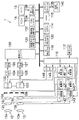
図1は、本発明に係る複眼撮像装置である複眼撮像装置1の外観図であり、(a)は正面斜視図であり、(b)は背面図である。複眼撮像装置1は、複数(図1では2個を例示)の撮像系を備えた複眼撮像装置1であって、同一被写体を複数視点(図1では左右二つの視点を例示)からみた立体画像や、単視点画像(2次元画像)が撮影可能である。また、複眼撮像装置1は、静止画に限らず、動画、音声の記録再生も可能である。
<First Embodiment>
1A and 1B are external views of a compound-
複眼撮像装置1のカメラボディ10は、略直方体の箱状に形成されており、その正面には、図1(a)に示すように、主として、バリア11、右撮像系12、左撮像系13、フラッシュ14、マイク15が設けられている。また、カメラボディ10の上面には、主として、レリーズスイッチ20、ズームボタン21が設けられている。
The
一方、カメラボディ10の背面には、図1(b)に示すように、モニタ16、モードボタン22、視差調整ボタン23、2D/3D切り替えボタン24、MENU/OKボタン25、十字ボタン26、DISP/BACKボタン27が設けられている。
On the other hand, on the back of the
バリア11は、カメラボディ10の前面に摺動可能に装着され、バリア11が上下に摺動することにより開状態と閉状態とが切り替えられる。通常は、図1(a)点線に示すように、バリア11は上端、すなわち閉状態に位置されており、対物レンズ12a、13a等はバリア11によって覆われている。これにより、レンズなどの破損が防止される。バリア11が摺動されることにより、バリアが下端、すなわち開状態に位置される(図1(a)実線参照)と、カメラボディ10前面に配設されたレンズ等が露呈される。図示しないセンサによりバリア11が開状態であることが認識されると、CPU110(図2参照)により電源がONされ、撮影が可能となる。
The barrier 11 is slidably attached to the front surface of the
右目用の画像を撮影する右撮像系12及び左目用の画像を撮影する左撮像系13は、撮影レンズ群と、絞り兼用メカシャッタ12d、13d(図2参照)と、これらを収納する鏡筒とを含む光学ユニットである。右撮像系12及び左撮像系13の撮影レンズ群は、屈曲光学系であり、主として、被写体からの光を取り込む対物レンズ12a、13a、対物レンズから入射した光路を略垂直に折り曲げるプリズム(図示せず)、フォーカスレンズ12b、13b(図2参照)、ズームレンズ12c、13c(図2参照)等で構成される。対物レンズ12a、13aは鏡筒前面に露出して設けられ、プリズム、フォーカスレンズ12b、13b、ズームレンズ12c、13c、絞り兼用メカシャッタ12d、13d等は鏡筒内部に設けられる。
The
フラッシュ14は、キセノン管で構成されており、暗い被写体を撮影する場合や逆光時などに必要に応じて被写体に閃光を照射する。
The
モニタ16は、4:3の一般的なアスペクト比を有するカラー表示が可能な液晶モニタであり、立体画像と平面画像の両方が表示可能である。モニタ16の詳細な構造は図示しないが、モニタ16は、その表面にパララックスバリア表示層を備えたパララックスバリア式3Dモニタである。モニタ16は、各種設定操作を行なう際の使用者インターフェース表示パネルとして利用され、画像撮影時には電子ビューファインダとして利用される。
The
モニタ16は、立体画像を表示するモード(3Dモード)と、平面画像を表示するモード(2Dモード)とが切り替えが可能である。3Dモードにおいては、モニタ16のパララックスバリア表示層に光透過部と光遮蔽部とが交互に所定のピッチで並んだパターンからなるパララックスバリアを発生させるとともに、その下層の画像表示面に左右の像を示す短冊状の画像断片を交互に配列して表示する。2Dモードや使用者インターフェース表示パネルとして利用される場合には、パララックスバリア表示層には何も表示せず、その下層の画像表示面に1枚の画像をそのまま表示する。
The
なお、モニタ16は、パララックスバリア式には限定されず、レンチキュラー方式、マイクロレンズアレイシートを用いるインテグラルフォトグラフィ方式、干渉現象を用いるホログラフィー方式などが採用されてもよい。また、モニタ16は液晶モニタに限定されず、有機ELなどが採用されてもよい。
The
レリーズスイッチ20は、いわゆる「半押し」と「全押し」とからなる二段ストローク式のスイッチで構成されている。複眼撮像装置1は、静止画撮影時(例えば、モードボタン22で静止画撮影モード選択時、又はメニューから静止画撮影モード選択時)、このレリーズスイッチ20を半押しすると撮影準備処理、すなわち、AE(Automatic Exposure:自動露出)、AF(Auto Focus:自動焦点合わせ)、AWB(Automatic White Balance:自動ホワイトバランス)の各処理を行い、全押しすると、画像の撮影・記録処理を行う。また、動画撮影時(例えば、モードボタン24で動画撮影モード選択時、又はメニューから動画撮影モード選択時)、このレリーズスイッチ20を全押しすると、動画の撮影を開始し、再度全押しすると、撮影を終了する。
The
ズームボタン21は、右撮像系12及び左撮像系13のズーム操作に用いられ、望遠側へのズームを指示するズームテレボタン21Tと、広角側へのズームを指示するズームワイドボタン21Wとで構成されている。
The
モードボタン22は、デジタルカメラ1の撮影モードを設定する撮影モード設定手段として機能し、このモードボタン22の設定位置により、デジタルカメラ1の撮影モードが様々なモードに設定される。撮影モードは、動画撮影を行う「動画撮影モード」と、静止画撮影を行う「静止画撮影モード」とに分けられ、「静止画撮影モード」は例えば、絞り、シャッタスピード等がデジタルカメラ1によって自動的に設定される「オート撮影モード」、人物の顔を抽出して撮影を行う「顔抽出撮影モード」、動体撮影に適した「スポーツ撮影モード」、風景の撮影に適した「風景撮影モード」、夕景及び夜景の撮影に適した「夜景撮影モード」、絞りの目盛りを使用者が設定し、シャッタスピードをデジタルカメラ1が自動的に設定する「絞り優先撮影モード」、シャッタスピードを使用者が設定し、絞りの目盛りをデジタルカメラ1が自動的に設定する「シャッタスピード優先撮影モード」、絞り、シャッタスピード等を使用者が設定する「マニュアル撮影モード」等がある。
The
視差調整ボタン23は、立体画像撮影時に視差を電子的に調整するボタンである。視差調整ボタン23の右側を押下することにより、右撮像系12で撮影された画像と左撮像系13で撮影された画像との視差が所定の距離だけ大きくなり、視差調整ボタン23の左側を押下することにより、右撮像系12で撮影された画像と左撮像系13で撮影された画像との視差が所定の距離だけ小さくなる。
The
2D/3D切り替えボタン24は、単視点画像を撮影する2D撮影モードと、多視点画像を撮影する3D撮影モードの切り替えを指示するためのスイッチである。
The 2D /
MENU/OKボタン25は、撮影及び再生機能の各種設定画面(メニュー画面)の呼び出し(MENU機能)に用いられるとともに、選択内容の確定、処理の実行指示等(OK機能)に用いられ、複眼撮像装置1が持つ全ての調整項目の設定が行われる。撮影時にMENU/OKボタン25が押されると、モニタ16にたとえば露出値、色合い、ISO感度、記録画素数などの画質調整などの設定画面が表示され、再生時にMENU/OKボタン25が押されると、モニタ16に画像の消去などの設定画面が表示される。複眼撮像装置1は、このメニュー画面で設定された条件に応じて動作する。
The MENU /
十字ボタン26は、各種のメニューの設定や選択あるいはズームを行うためのボタンであり、上下左右4方向に押圧操作可能に設けられており、各方向のボタンには、カメラの設定状態に応じた機能が割り当てられる。たとえば、撮影時には、左ボタンにマクロ機能のON/OFFを切り替える機能が割り当てられ、右ボタンにフラッシュモードを切り替える機能が割り当てられる。また、上ボタンにモニタ16の明るさを替える機能が割り当てられ、下ボタンにセルフタイマのON/OFFや時間を切り替える機能が割り当てられる。また、再生時には、右ボタンにコマ送りの機能が割り当てられ、左ボタンにコマ戻しの機能が割り当てられる。また、上ボタンに再生中の画像を削除する機能が割り当てられる。また、各種設定時には、モニタ16に表示されたカーソルを各ボタンの方向に移動させる機能が割り当てられる。
The
DISP/BACKボタン27は、モニタ16の表示切り替えを指示するボタンとして機能し、撮影中、このDISP/BACKボタン27が押されると、モニタ16の表示がON→フレーミングガイド表示→OFFに切り替えられる。また、再生中、このDISP/BACKボタン27が押されると、通常再生→文字表示なし再生→マルチ再生に切り替えられる。また、DISP/BACKボタン27は、入力操作のキャンセルや一つ前の操作状態に戻すことを指示するボタンとして機能する。
The DISP /
図2は、複眼撮像装置1の主要な内部構成を示すブロック図である。複眼撮像装置1は、主として、CPU110、操作手段(レリーズボタン20、MENU/OKボタン25、十字ボタン26等)112、SDRAM114、VRAM116、AF検手段118、AE/AWB検出手段120、撮像素子122、123、CDS/AMP124、125、A/D変換器126、127、画像入力コントローラ128、画像信号処理手段130、立体画像信号処理部133、圧縮伸張処理手段132、ビデオエンコーダ134、メディアコントローラ136、音入力処理部138、記録メディア140、フォーカスレンズ駆動部142、143、ズームレンズ駆動部144、145、絞り駆動部146、147、タイミングジェネレータ(TG)148、149とで構成される。
FIG. 2 is a block diagram showing a main internal configuration of the compound
CPU110は、複眼撮像装置1の全体の動作を統括的に制御する。CPU110は、右撮像系12と左撮像系13の動作を制御する。右撮像系12と左撮像系13とは、基本的に連動して動作を行うが、各々個別に動作させることも可能である。また、CPU110は、右撮像系12及び左撮像系13で得られた2つの画像データを短冊状の画像断片とし、これがモニタ16に交互に表示されるような表示用画像データを生成する。3Dモードで表示を行う際に、パララックスバリア表示層に光透過部と光遮蔽部とが交互に所定のピッチで並んだパターンからなるパララックスバリアを発生させるとともに、その下層の画像表示面に左右の像を示す短冊状の画像断片を交互に配列して表示することで立体視を可能にする。
The
SDRAM114には、このCPU110が実行する制御プログラムであるファームウェアを含む各種プログラム、制御に必要な各種データ、カメラ設定値等が記録されている。
The
VRAM116は、画像表示用の一時メモリであり、CPU110の作業用領域としても利用される。
The
AF検出手段118は、CPU110からの指令に従い、右撮像系12、左撮像系13からそれぞれ入力された画像信号から所定のフォーカスエリア(合焦評価領域)における合焦評価値を算出する。AF検出手段118は、入力された画像信号の高周波成分のみを通過させるハイパスフィルタ、絶対値化処理部、所定のフォーカスエリア内の信号を切り出すフォーカスエリア抽出部、そのフォーカスエリア内の絶対値データを積算する積算部等を備えて構成され、積算部で積算された値を合焦評価値としてCPU110に出力する。
The AF detection means 118 calculates a focus evaluation value in a predetermined focus area (focus evaluation area) from image signals input from the
本実施の形態の複眼撮像装置1では、撮像素子122、123から得られる画像のコントラストによりAF制御が行われ(いわゆるコントラストAF)、AF検出手段118は、入力された画像信号から画像の鮮鋭度を示す合焦評価値を算出する。CPU110は、このAF検出手段118で算出される合焦評価値が極大となる位置を検出し、その位置にフォーカスレンズ12b、13bを移動させる。すなわち、フォーカスレンズ12b、13bを所定のサーチ範囲(MODから無限遠まで)内で所定のステップで移動させ、各位置で合焦評価値を取得し、得られた合焦評価値が最大の位置を合焦位置として、その位置にフォーカスレンズ12b、13bを移動させる。なお、MODとは、通常撮影領域の至近側の限界を意味する言葉であり、AF時のフォーカスレンズ12b、13bの至近側の駆動限界も同じである。
In the compound
AE/AWB検出回路120は、CPU110からの指令に従い、入力された画像信号からAE制御及びAWB制御に必要な物理量を算出する。たとえば、AE制御に必要な物理量として、1画面を複数のエリア(たとえば16×16)に分割し、分割したエリアごとにR、G、Bの画像信号の積算値を算出する。CPU110は、このAE/AWB検出回路120から得た積算値に基づいて被写体の明るさ(被写体輝度)を検出し、撮影に適した露出値(撮影EV値)を算出する。そして、算出した撮影EV値と所定のプログラム線図から絞り値とシャッタスピードを決定する。また、AWB制御に必要な物理量として、1画面を複数のエリア(例えば、16×16)に分割し、分割したエリアごとにR、G、Bの画像信号の色別の平均積算値を算出する。CPU110は、得られたRの積算値、Bの積算値、Gの積算値から分割エリアごとにR/G及びB/Gの比を求め、求めたR/G、B/Gの値のR/G、B/Gの色空間における分布等に基づいて光源種判別を行う。そして、判別された光源種に適したホワイトバランス調整値に従って、たとえば各比の値がおよそ1(つまり、1画面においてRGBの積算比率がR:G:B≒1:1:1)になるように、ホワイトバランス調整回路のR、G、B信号に対するゲイン値(ホワイトバランス補正値)を決定する。
The AE /
撮像素子122、123は、所定のカラーフィルタ配列(例えば、ハニカム配列、ベイヤ配列)のR、G、Bのカラーフィルタが設けられたカラーCCDで構成されている。撮像素子122、123は、フォーカスレンズ12b、13b、ズームレンズ12c、13c等によって結像された被写体光を受光し、この受光面に入射した光は、その受光面に配列された各フォトダイオードによって入射光量に応じた量の信号電荷に変換される。撮像素子122、123の光電荷蓄積・転送動作は、TG148、149からそれぞれ入力される電荷排出パルスに基づいて電子シャッタ速度(光電荷蓄積時間)が決定される。
The
すなわち、撮像素子122、123に電荷排出パルスが入力されている場合には、撮像素子122、123に電荷が蓄えられることなく排出される。それに対し、撮像素子122、123に電荷排出パルスが入力されなくなると、電荷が排出されなくなるため、撮像素子122、123において電荷蓄積、すなわち露光が開始される。撮像素子122、123で取得された撮像信号は、TG148、149からそれぞれ与えられる駆動パルスに基づいてCDS/AMP124、125に出力される。
That is, when a charge discharge pulse is input to the
CDS/AMP124、125は、撮像素子122、123から出力された画像信号に対して相関二重サンプリング処理(撮像素子の出力信号に含まれるノイズ(特に熱雑音)等を軽減することを目的として、撮像素子の1画素毎の出力信号に含まれるフィードスルー成分レベルと画素信号成分レベルとの差をとることにより正確な画素データを得る処理)を行い、増幅してR、G、Bのアナログの画像信号を生成する。
The CDS /
A/D変換器126、127は、CDS/AMP124、125で生成されたR、G、Bのアナログの画像信号デジタルの画像信号に変換する。
The A /
画像入力コントローラ128は、所定容量のラインバッファを内蔵しており、CPU110からの指令に従い、CDS/AMP/AD変換部から出力された1画像分の画像信号を蓄積して、VRAM116に記録する。
The
画像信号処理手段130は、同時化回路(単板CCDのカラーフィルタ配列に伴う色信号の空間的なズレを補間して色信号の位相を合わせる処理回路)、ホワイトバランス補正回路、ガンマ補正回路、輪郭補正回路、輝度・色差信号生成回路等を含み、CPU110からの指令に従い、入力された画像信号に所要の信号処理を施して、輝度データ(Yデータ)と色差データ(Cr,Cbデータ)とからなる画像データ(YUVデータ)を生成する。
The image signal processing means 130 includes a synchronization circuit (a processing circuit that interpolates a spatial shift of the color signal associated with the color filter array of the single CCD and adjusts the phase of the color signal), a white balance correction circuit, a gamma correction circuit, It includes a contour correction circuit, a luminance / color difference signal generation circuit, etc., and performs necessary signal processing on the input image signal in accordance with a command from the
圧縮伸張処理手段132は、CPU110からの指令に従い、入力された画像データに所定形式の圧縮処理を施し、圧縮画像データを生成する。また、CPU110からの指令に従い、入力された圧縮画像データに所定形式の伸張処理を施し、非圧縮の画像データを生成する。
The compression /
ビデオエンコーダ134は、モニタ16への表示を制御する。すなわち、記録メディア140などに保存された画像信号をモニタ16に表示するための映像信号(たとえば、NTSC信号やPAL信号、SCAM信号)に変換してモニタ16に出力するとともに、必要に応じて所定の文字、図形情報をモニタ16に出力する。なお、モニタ16がデジタル信号に対応可能な場合は、ビデオエンコーダ134は不要であり、図示しない信号変換回路でモニタ16の仕様に合わせた形式のデジタル信号がモニタ16に入力される。
The
メディアコントローラ136は、圧縮伸張処理手段132で圧縮処理された各画像データを記録メディア140に記録する。
The media controller 136 records each image data compressed by the compression /
音入力処理部138には、マイク15から入力され、図示しないステレオマイクアンプで増幅された音声信号が入力され、この音声信号の符号化処理を行う。
A sound signal input from the
記録メディア140は、複眼撮像装置1に着脱自在なxDピクチャカード(登録商標)、SDカード(登録商標)に代表される半導体メモリカード、可搬型小型ハードディスク、磁気ディスク、光ディスク、光磁気ディスク等、種々の記録媒体である。
The
フォーカスレンズ駆動部142、143は、CPU110からの指令に従い、フォーカスレンズ12b、13bをそれぞれ光軸方向に移動させ、焦点位置を可変する。
The focus
ズームレンズ駆動部144、145は、CPU110からの指令に従い、ズームレンズ12c、13cそれぞれ光軸方向に移動させ、焦点距離を可変する。
The zoom
絞り兼用メカシャッタ12d、13dは、それぞれ絞り駆動部146、147のアイリスモータに駆動されることにより、その開口量を可変して、撮像素子122、123への入射光量を調整する。
The aperture /
絞り駆動部146、147は、CPU110からの指令に従い、絞り兼用メカシャッタ12d、13dの開口量を可変して、撮像素子122、123への入射光量をそれぞれ調整する。また、絞り駆動部146、147は、CPU110からの指令に従い、絞り兼用メカシャッタ12d、13dを開閉して、撮像素子122、123への露光/遮光それぞれを行う。
The
以上のように構成された複眼撮像装置1の作用について説明する。バリア11を閉状態から開状態へと摺動させると、複眼撮像装置1の電源が投入され、複眼撮像装置1は、撮影モードの下で起動する。撮影モードとしては、2Dモードと、同一被写体を2視点からみた立体画像を撮影する3D撮影モードとが設定可能である。撮影モードの設定は、複眼撮像装置1が撮影モードで駆動中にMENU/OKボタン25が押下されることによりモニタ16に表示されるメニュー画面から設定可能である。
以下の処理は、主としてCPU50で行われる。
The operation of the compound
The following processing is mainly performed by the CPU 50.
(1)2D撮影モード
CPU110は、右撮像系12又は左撮像系13(本実施の形態では左撮像系13)を選択し、左撮像系13の撮像素子123によってライブビュー画像用の撮影を開始する。すなわち、撮像素子123で連続的に画像が撮像され、その画像信号が連続的に処理されて、ライブビュー画像用の画像データが生成される。
(1) 2D shooting mode The
CPU110は、モニタ16を2Dモードとし、生成された画像データを順次ビデオエンコーダ134に加え、表示用の信号形式に変換してモニタ16に出力する。これにより、撮像素子123で捉えた画像がモニタ16にスルー表示される。モニタ16の入力がデジタル信号に対応している場合にはビデオエンコーダ134は不要であるが、モニタ16の入力仕様に合致した信号形態に変換する必要がある。
The
ユーザ(使用者)は、モニタ16に表示されるスルー画像を見ながらフレーミングしたり、撮影したい被写体を確認したり、撮影後の画像を確認したり、撮影条件を設定したりする。
A user (user) performs framing while viewing a through image displayed on the
上記撮影スタンバイ状態時にレリーズスイッチ20が半押しされると、CPU110にS1ON信号が入力される。CPU110はこれを検知し、AE測光、AF制御を行う。AE測光時には、撮像素子123を介して取り込まれる画像信号の積算値等に基づいて被写体の明るさを測光する。この測光した値(測光値)は、本撮影時における絞り兼用メカシャッタ13dの絞り値、及びシャッタ速度の決定に使用される。同時に、検出された被写体輝度より、フラッシュ14の発光が必要かどうかを判断する。フラッシュ14の発光が必要と判断された場合には、フラッシュ14をプリ発光させ、その反射光に基づいて本撮影時のフラッシュ14の発光量を決定する。
When the
また、CPU110は、AF制御時にはフォーカスレンズを至近から無限遠に対応するレンズ位置に順次移動させるとともに、レンズ位置毎に撮像素子123を介して取り込まれた画像のAFエリアの画像信号に基づいて画像信号の高周波成分を積算した合焦評価値をAF検出手段118から取得し、この評価値がピークとなるレンズ位置を求め、そのレンズ位置にフォーカスレンズを移動させるコントラストAFを行う。
Further, the
レリーズスイッチ20が全押しされると、CPU110にS2ON信号が入力される。CPU110は、このS2ON信号に応動して、撮影、記録処理を実行する。
When the
まず、CPU110は、前記測光値に基づいて決定した絞り値に基づいて絞り駆動部147を介して絞り兼用メカシャッタ13dを駆動するとともに、前記測光値に基づいて決定したシャッタ速度になるように撮像素子123での電荷蓄積時間(いわゆる電子シャッタ)を制御する。
First, the
この際、フラッシュ14を発光させる場合は、プリ発光の結果から求めたフラッシュ14の発光量に基づいてフラッシュ14を発光させる。
At this time, when the
被写体光は、フォーカスレンズ13b、ズームレンズ13c、絞り兼用メカシャッタ13d、赤外線カットフィルタ46、及び光学ローパスフィルタ48等を介して撮像素子123の受光面に入射する。
Subject light is incident on the light receiving surface of the
撮像素子123の各フォトダイオードに蓄積された信号電荷は、TG149から加えられるタイミング信号に従って読み出され、電圧信号(画像信号)として撮像素子123から順次出力され、CDS/AMP125に入力される。
The signal charges accumulated in each photodiode of the
CDS/AMP125は、CDSパルスに基づいてCCD出力信号を相関二重サンプリング処理し、CPU110から加えられる撮影感度設定用ゲインによってCDS回路から出力される画像信号を増幅する。
The CDS /
CDS/AMP125から出力されたアナログの画像信号は、A/D変換器127において、デジタルの画像信号に変換され、この変換された画像信号(R、G、BのRAWデータ)は、SDRAM114に転送され、ここに一旦蓄えられる。
The analog image signal output from the CDS /
SDRAM114から読み出されたR、G、Bの画像信号は、画像信号処理手段130に入力される。画像信号処理手段130では、ホワイトバランス調整回路によりR、G、Bの画像信号ごとにデジタルゲインをかけることでホワイトバランス調整が行われ、ガンマ補正回路によりガンマ特性に応じた階調変換処理が行われ、単板CCDのカラーフィルタ配列に伴う各色信号の空間的なズレを補間して色信号の位相を合わせる同時化処理が行われる。同時化されたR、G、Bの画像信号は、更に輝度・色差データ生成回路により輝度信号Yと色差信号Cr、Cb(YC信号)に変換され、Y信号は、輪郭補正回路により輪郭強調処理される。画像信号処理手段130で処理されたYC信号は再びSDRAM114に蓄えられる。
The R, G, and B image signals read from the
上記のようにしてSDRAM114に蓄えられたYC信号は、圧縮伸長処理手段132によって圧縮され、所定のフォーマットの画像ファイルとして、メディアコントローラ136を介して記録メディア140に記録される。静止画のデータは、Exif規格に従った画像ファイルとして記録メディア140に格納される。Exifファイルは、主画像のデータを格納する領域と、縮小画像(サムネイル画像)のデータを格納する領域とを有している。撮影によって取得された主画像のデータから画素の間引き処理その他の必要なデータ処理を経て、規定サイズ(例えば、160×120又は80×60ピクセルなど)のサムネイル画像が生成される。こうして生成されたサムネイル画像は、主画像とともにExifファイル内に書き込まれる。また、Exifファイルには、撮影日時、撮影条件、顔検出情報等のタグ情報が付属されている。
The YC signal stored in the
(2)3D撮影モード
CPU110は、撮像素子122及び撮像素子123によってライブビュー画像用の撮影を開始する。すなわち、撮像素子122及び撮像素子123で同じ被写体が連続的に撮像され、その画像信号が連続的に処理され、ライブビュー画像用の立体画像データが生成される。CPU110はモニタ16を3Dモードに設定し、生成された画像データはビデオエンコーダ134で順次表示用の信号形式に変換されて、それぞれモニタ16に出力される。
(2) 3D Shooting Mode The
生成された画像データは、順次ビデオエンコーダ134に加えられ、表示用の信号形式に変換されて、モニタ16に出力される。これにより、ライブビュー画像用の立体画像データがモニタ16にスルー表示される。
The generated image data is sequentially added to the
ユーザ(使用者)は、モニタ16に表示されるスルー画像を見ながらフレーミングしたり、撮影したい被写体を確認したり、撮影後の画像を確認したり、撮影条件を設定したりする。
A user (user) performs framing while viewing a through image displayed on the
上記撮影スタンバイ状態時にレリーズスイッチ20が半押しされると、CPU110にS1ON信号が入力される。CPU110はこれを検知し、AE測光、AF制御を行う。AE測光は、右撮像系12又は左撮像系13(本実施の形態では左撮像系13)の一方で行う。また、AF制御は、右撮像系12及び左撮像系13のそれぞれで行う。AE測光は2D撮影モードと同一であるため、詳細な説明を省略する。
When the
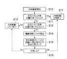
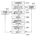
図3は、3D撮影モードのAF制御の処理の流れを示すフローチャートである。CPU110は、レリーズボタンの半押しに応じて合焦駆動を開始する(ステップS10)。
FIG. 3 is a flowchart showing a flow of AF control processing in the 3D shooting mode. The
すなわち、CPU110は、フォーカスレンズ駆動部142、143をそれぞれ制御して、フォーカスレンズ12b、13bの位置を初期位置に移動させる。CPU110は、フォーカスレンズ12b、13bを合焦のためのサーチ範囲(MODから無限遠まで)でステップ駆動により所定単位ずつ(例えばサーチ範囲を50の段階に等分割した場合の1単位)移動させる。フォーカスレンズ12b、13bの移動方向は、望遠側から至近側へでも良いし、至近側から望遠側でもよい。
That is, the
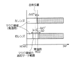
図4は、ユーザが工場出荷(以下、常温という)時の温度より高い温度(以下、高温という)で使用した場合のサーチ範囲を示す模式図である。複眼撮像装置1は、常温下で右撮像系12、左撮像系13のMOD(常温時MOD)が一致するように調整されているが、レンズや鏡筒の寸法変化等により温度により撮像系12、左撮像系13のMODが変化する。右撮像系12、左撮像系13は異なる鏡筒、異なるフォーカスレンズを用いているため、高温下でのMOD(高温時MOD)は右撮像系12、左撮像系13で異なることとなる。したがって、フォーカスレンズ12b、13bのサーチ範囲は異なる範囲となる。
FIG. 4 is a schematic diagram showing a search range when the user uses at a temperature (hereinafter referred to as high temperature) higher than the temperature at the time of factory shipment (hereinafter referred to as normal temperature). The compound-
CPU110は、所定単位ずつステップ駆動されるごとに撮像素子122、123を介して画像データを取得する。AF検出手段118は、取得された画像データのうち所定のエリア(例えば画面中心近傍の矩形領域)の画像データに基づいて被写体像の鮮鋭度を示す合焦評価値を算出する。
The
AF検出手段118は、全てのフォーカスレンズ位置で算出した合焦評価値に基づいて、各レンズ位置と合焦評価値との関係を表す合焦曲線を求める。CPU110は、右撮像系12及び左撮像系13の両方についての合焦曲線の極大点(ピーク)の位置が検出可能か否か、すなわち左右の両方の撮像系で合焦位置が見つかったか否かを判断する(ステップS11)。図4に示すように、右撮像系12、左撮像系13は同じ被写体が撮影対象であるため、フォーカスレンズの位置が同じであれば、合焦評価値はほぼ同じとなる。すなわち、フォーカスレンズの位置を一致させた場合には、右撮像系12、左撮像系13の合焦曲線はほぼ同じとなる。この場合には、右撮像系12の合焦曲線のからはピークが検出可能である。しかしながら、ピークが検出されたフォーカスレンズ12bの位置は左撮像系13のサーチ範囲からはずれているため、左撮像系13の合焦曲線からはピークが検出できない。したがって、この場合には、ステップS11において左右のいずれかの撮像系で合焦位置が見つかったと判断される。
The
左右の両方の撮像系で合焦位置が見つかった場合(ステップS11でYES)は、正常にAF処理が行われた場合であるため、AF制御処理が終了される(ステップS17)。 If the in-focus positions are found in both the left and right imaging systems (YES in step S11), the AF control process is terminated because the AF process is normally performed (step S17).
左右の両方の撮像系で合焦位置が見つからなかった場合(ステップS11でNO)には、左右のいずれの撮像系でも合焦位置が見つからなかったか否かが判断される(ステップS12)。左右のいずれの撮像系でも合焦位置が見つからなかった場合(ステップS12でYES)には、合焦位置が検出されない場合であるため、正常にAF処理が行われなかったとして、AF制御処理が終了される(ステップS13)。この時、CPU110は、モニタ16にAF制御ができなかったことを示すエラー表示を表示させる。
If the in-focus position is not found in both the left and right imaging systems (NO in step S11), it is determined whether or not the in-focus position is found in either of the left and right imaging systems (step S12). If the in-focus position is not found in either of the left and right imaging systems (YES in step S12), the in-focus position is not detected. The process is terminated (step S13). At this time, the
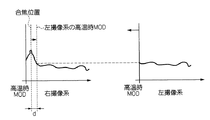
左右のいずれかの撮像系で合焦位置が見つかった場合(ステップS12でNO)には、温度によるサーチ範囲の変化により左右のいずれかの撮像系で合焦位置が見つからない場合である。したがって、CPU110は、右撮像系12の合焦曲線及び左撮像系13の合焦曲線に基づいて、合焦位置が見つからなかった撮像系の合焦位置を検出するためにフォーカスレンズを移動させる距離dを算出する(ステップS14)。フォーカスレンズの位置を一致させた場合には、右撮像系12、左撮像系13の合焦曲線はほぼ同じとなる。そこで、図5に示すように、右撮像系12の合焦曲線と左撮像系13の合焦曲線とを重ね合わせることで、ピークが検出されない左撮像系13の合焦曲線が、ピークが検出された右撮像系12の合焦曲線のどこに該当するのかを調べる。そして、左撮像系13の高温時MODの位置と、右撮像系12の合焦位置との差を距離dとして算出する。
When the in-focus position is found in either of the left and right imaging systems (NO in step S12), the in-focus position is not found in either of the left or right imaging systems due to a change in the search range due to temperature. Therefore, the
CPU110は、合焦位置が検出されなかった撮像系のフォーカスレンズを、MODから距離d+固定値分だけ至近側の位置とMODとの間の範囲を追加サーチ範囲としてステップS11と同様の方法により合焦動作を行い、合焦曲線を求める(ステップS15)。図4に示す場合では、CPU110は、追加サーチ範囲でフォーカスレンズ13bをステップ駆動により所定単位ずつ移動させ、画像データを取得し、合焦評価値を算出する処理を繰り返し行うことで、追加サーチ範囲についての合焦曲線を求める。フォーカスレンズ13bの移動方向は、望遠側から至近側へでも良いし、至近側から望遠側でもよい。なお、ステップS15において、距離dに固定値を追加するのは、誤差により合焦曲線のピークが検出されないことを防止するためであるが、固定値の追加は必須ではない。
The
CPU110は、ステップS15で行われた追加サーチにより、ステップS12で合焦位置が検出されなかった撮像系についてピークが検出されたか否か、すなわち合焦位置が検出されたか否かを判断する(ステップS16)。合焦位置が検出された場合(ステップS16でYES)には、正常にAF処理が行われたとして、AF制御処理が終了される(ステップS17)。合焦位置が検出されなかった場合(ステップS16でNO)には、正常にAF処理が行われなかったとしてAF処理が終了される(ステップS13)。これにより、撮像系の固体差が原因で、通常のAF処理では左右の撮像系のいずれか一方で合焦位置が検出されない場合にも、左右の撮像系の両方で合焦位置を検出することができる。
レリーズスイッチ20が全押しされると、CPU110にS2ON信号が入力される。CPU110は、このS2ON信号に応動して、撮影、記録処理を実行する。右撮像系12及び左撮像系13のそれぞれで撮影された画像データを生成する処理については、2D撮影モードと同一であるため、説明を省略する。
When the
CDS/AMP124、125でそれぞれ生成された2枚の画像データからは、2D撮影モードと同様の方法により、圧縮画像データが2個生成される。圧縮された2枚の画像データは、関連付けされた状態で記憶メディア137に記録される。
Two pieces of compressed image data are generated from the two pieces of image data respectively generated by the CDS /
複眼撮像装置1のモードを再生モードに設定すると、CPU110は、メディアコントローラ136にコマンドを出力し、記録メディア140に最後に記録された画像ファイルを読み出させる。
When the mode of the compound-
読み出された画像ファイルの圧縮画像データは、圧縮・伸張回路148に加えられ、非圧縮の輝度/色差信号に伸張され、立体画像信号処理部133で立体画像とされたのち、ビデオエンコーダ134を介してモニタ16に出力される。これにより、記録メディア140に記録されている画像がモニタ16に再生表示される(1枚画像の再生)。
The compressed image data of the read image file is added to the compression /
1枚画像の再生においては、2D撮影モードで撮影された画像は、画像がモニタ16全面に2Dモードで表示され、テレ/ワイド同時撮りモードで撮影された画像は、図7に示すようにテレ側の画像とワイド側の画像とが並んで表示され、3Dモードで撮影された画像は、画像がモニタ16全面に3Dモードで表示される。
In the reproduction of a single image, an image shot in the 2D shooting mode is displayed in the 2D mode on the entire surface of the
画像のコマ送りは、十字ボタン26の左右のキー操作によって行なわれ、十字ボタン26の右キーが押されると、次の画像ファイルが記録メディア140から読み出され、モニタ16に再生表示される。また、十字ボタンの左キーが押されると、一つ前の画像ファイルが記録メディア140から読み出され、モニタ16に再生表示される。モニタ16に再生表示された画像を確認しながら、必要に応じて、記録メディア140に記録された画像を消去することができる。画像の消去は、画像がモニタ16に再生表示された状態でMENU/OKボタン25が押下されることによって行われる。
Image frame advance is performed by operating the left and right keys of the
本実施の形態によれば、撮像系の固体差が原因で、通常のAF処理では左右の撮像系のいずれか一方で合焦位置が検出されない場合にも、左右の撮像系の両方で合焦位置を検出することができる。 According to the present embodiment, even when the focus position is not detected by one of the left and right imaging systems in the normal AF process due to the individual difference between the imaging systems, the focusing is performed by both the left and right imaging systems. The position can be detected.
また、本実施の携帯では、合焦評価値に基づいて追加サーチ範囲を決定するため、最初(ステップS11)のサーチで合焦位置が検出されなかった場合においても、追加サーチ(ステップS15)で確実に合焦位置を検出することができる。 In addition, since the additional search range is determined based on the focus evaluation value in the mobile phone of the present embodiment, even if the in-focus position is not detected in the initial search (step S11), the additional search (step S15) is performed. The in-focus position can be reliably detected.
なお、本実施の形態では、MODと無限遠との間をサーチ範囲としてAF制御をした場合に一方の撮像系で合焦位置が検出されなかった場合を例に説明したが、マクロ領域でも同様の処理が可能である。図6は、左撮像系13はマクロ領域で合焦位置が検出されたが右撮像系12はマクロ領域で合焦位置が検出されなかった場合を示す。この場合は、図7に示すように、右撮像系12の合焦曲線と左撮像系13の合焦曲線とを重ねることで距離dを算出し、距離dだけ望遠側にマクロ領域のサーチ範囲を広げることにより、右撮像系12についても合焦位置を検出することができる。
In the present embodiment, the case where the focus position is not detected by one imaging system when AF control is performed with the search range between MOD and infinity as an example has been described, but the same applies to the macro region. Can be processed. FIG. 6 shows a case where the
<第2の実施の形態>
本発明の第1の実施の形態は、通常のAF処理では左右の撮像系のいずれか一方で合焦位置が検出されない場合に、合焦曲線に基づいて追加サーチ範囲を算出するものであるが、追加サーチ範囲を算出する方法はこれに限らない。
<Second Embodiment>
The first embodiment of the present invention calculates an additional search range based on a focus curve when the focus position is not detected by either one of the left and right imaging systems in normal AF processing. The method for calculating the additional search range is not limited to this.
本発明の第2の実施の形態は、温度変化によるサーチ範囲の変化量に基づいて追加サーチ範囲を算出するものである。以下、第2の実施の形態の複眼撮像装置2について説明する。なお、第1の実施の形態と同一の部分については同一の符号を付し、説明を省略する。
In the second embodiment of the present invention, an additional search range is calculated based on a change amount of the search range due to a temperature change. Hereinafter, the compound
図8は、複眼撮像装置2の主要な内部構成を示すブロック図である。複眼撮像装置1は、主として、CPU110、操作手段(レリーズボタン20、MENU/OKボタン25、十字ボタン26等)112、SDRAM114、VRAM116、AF検手段118、AE/AWB検出手段120、撮像素子122、123、CDS/AMP124、125、A/D変換器126、127、画像入力コントローラ128、画像信号処理手段130、立体画像信号処理部133、圧縮伸張処理手段132、ビデオエンコーダ134、メディアコントローラ136、音入力処理部138、記録メディア140、フォーカスレンズ駆動部142、143、ズームレンズ駆動部144、145、絞り駆動部146、147、タイミングジェネレータ(TG)148、149、温度検出手段150とで構成される。
FIG. 8 is a block diagram showing the main internal configuration of the compound
温度検出手段150は、右撮像系12及び左撮像系13の温度を検出するものであり、右撮像系12の鏡筒表面に設けられる。左撮像系13の温度は直接測定されないが、右撮像系12及び左撮像系13は複眼撮像装置2の内部に近接して設けられるため、右撮像系12の温度と左撮像系13の温度が同じであると推定されるため、温度検出手段150で検出された温度を右撮像系12及び左撮像系13の温度とすればよい。なお、本実施の形態では、温度検出手段150は1つであり、右撮像系12の鏡筒表面に設けられたが、温度検出手段150の数、配設位置はこれに限られない。例えば、温度検出手段150を2つ備え、温度検出手段150が右撮像系12の鏡筒、左撮像系13の鏡筒のそれぞれに設けられるようにしてもよい。また、温度検出手段150を1つとし、カメラボディ11に設けるようにしてもよい。この場合には、温度検出手段150は、右撮像系12及び左撮像系13にできるだけ近い位置であって、右撮像系12と左撮像系13との中間地点近傍に設けられるのが望ましい。
The
以上のように構成された複眼撮像装置2の作用について説明する。複眼撮像装置2の作用のうち、3D撮影モードのAF制御の処理のみ複眼撮像装置1と異なるため、以下、3D撮影モードのAF制御の処理についてのみ説明する。
The operation of the compound
図9は、複眼撮像装置2の3D撮影モードのAF制御の処理の流れを示すフローチャートである。
FIG. 9 is a flowchart showing a flow of AF control processing in the 3D shooting mode of the compound
CPU110は、レリーズボタンの半押しに応じて合焦駆動を開始する(ステップS10)。AF検出手段118は、サーチ範囲内の全てのフォーカスレンズ位置で画像データを取得し、各画像データに基づいて被写体像の鮮鋭度を示す合焦評価値を算出する。算出した合焦評価値に基づいて、各レンズ位置と合焦評価値との関係を表す合焦曲線を求める。CPU110は、右撮像系12及び左撮像系13の両方についての合焦曲線の極大点(ピーク)の位置が検出可能か否か、すなわち左右の両方の撮像系で合焦位置が見つかったか否かを判断する(ステップS11)。
The
左右の両方の撮像系で合焦位置が見つかった場合(ステップS11でYES)は、正常にAF処理が行われた場合であるため、AF制御処理が終了される(ステップS17)。 If the in-focus positions are found in both the left and right imaging systems (YES in step S11), the AF control process is terminated because the AF process is normally performed (step S17).
左右の両方の撮像系で合焦位置が見つからなかった場合(ステップS11でNO)には、左右のいずれの撮像系でも合焦位置が見つからなかったか否かが判断される(ステップS12)。左右のいずれの撮像系でも合焦位置が見つからなかった場合(ステップS12でYES)には、合焦位置が検出されない場合であるため、正常にAF処理が行われなかったとして、AF制御処理が終了される(ステップS13)。この時、CPU110は、モニタ16にAF制御ができなかったことを示すエラー表示を表示させる。
If the in-focus position is not found in both the left and right imaging systems (NO in step S11), it is determined whether or not the in-focus position is found in either of the left and right imaging systems (step S12). If the in-focus position is not found in either of the left and right imaging systems (YES in step S12), the in-focus position is not detected. The process is terminated (step S13). At this time, the
左右のいずれかの撮像系で合焦位置が見つかった場合(ステップS12でNO)には、温度によるサーチ範囲の変化により左右のいずれかの撮像系で合焦位置が見つからない場合である。したがって、CPU110は、温度検出手段150で検出された温度を取得し(ステップS20)、温度特性テーブル(図10参照)から追加サーチ範囲を取得する(ステップS21)。 When the in-focus position is found in either of the left and right imaging systems (NO in step S12), the in-focus position is not found in either of the left or right imaging systems due to a change in the search range due to temperature. Therefore, CPU110 acquires the temperature detected by the temperature detection means 150 (step S20), and acquires an additional search range from a temperature characteristic table (refer FIG. 10) (step S21).
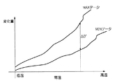
温度特性テーブルとは、図10に示すように、温度とサーチ範囲の変化量との関係を示すグラフであり、左右の撮像系の固体差により発生するサーチ範囲の差異を補正するために用いられる。温度特性テーブルは、あらかじめSDRAM114に記憶されている。サーチ範囲の変化量とは、常温時のサーチ範囲を基準としたときのサーチ範囲の変化量である。このサーチ範囲の変化量は、個体差を考慮した時の最大値であり、複数のサンプルを用いて温度を変化させながらサーチ範囲を測定したデータに基づいて、測定した各温度毎に求められる。
As shown in FIG. 10, the temperature characteristic table is a graph showing the relationship between the temperature and the amount of change in the search range, and is used to correct the difference in the search range caused by the individual difference between the left and right imaging systems. . The temperature characteristic table is stored in the
ステップS21では、CPU110は、この温度特性テーブルからステップS20で検出された温度におけるサーチ範囲の変化量ΔDを追加サーチ範囲として取得する。すなわち、CPU110は、MODから至近側へ変化量ΔDだけ離れた位置とMODとの間の範囲を追加サーチ範囲とする。
In step S21, the
そして、CPU110は、合焦位置が検出されなかった撮像系のフォーカスレンズを、MODから変化量ΔDだけ至近側の位置とMODとの間の範囲を追加サーチ範囲としてステップS11と同様の方法により合焦動作を行い、合焦曲線を求める(ステップS22)。図11に示す場合では、左撮像系13で合焦位置が検出されていないため、CPU110は、追加サーチ範囲でフォーカスレンズ13bをステップ駆動により所定単位ずつ至近側に移動させ、画像データを取得し、合焦評価値を算出する処理を繰り返し行うことで、追加サーチ範囲についての合焦曲線を求め、ピークを検出する。なお、第1の実施の形態において距離dに固定値を追加するのに対し、本実施の形態では固定値を追加しないが、これは変化量ΔDに誤差による許容量が含まれているため、すなわち、右撮像系12のサーチ範囲の変化量Δd1、左撮像系13のサーチ範囲の変化量Δd2ともにΔDよりも小さいためである。
Then, the
CPU110は、ステップS22で行われた追加サーチにより、ステップS12で合焦位置が検出されなかった撮像系について合焦位置が検出されたか否かを判断する(ステップS16)。合焦位置が検出された場合(ステップS16でYES)には、正常にAF処理が行われたとして、AF制御処理が終了される(ステップS17)。合焦位置が検出されなかった場合(ステップS16でNO)には、正常にAF処理が行われなかったとしてAF処理が終了される(ステップS13)。
本実施の形態によれば、撮像系の固体差が原因で、通常のAF処理では左右の撮像系のいずれか一方で合焦位置が検出されない場合にも、左右の撮像系の両方で合焦位置を検出することができる。 According to the present embodiment, even when the focus position is not detected by one of the left and right imaging systems in the normal AF process due to the individual difference between the imaging systems, the focusing is performed by both the left and right imaging systems. The position can be detected.
また、あらかじめ記憶された温度特性テーブルに基づいて追加サーチ範囲を決定するため、簡単な処理で追加サーチ範囲を決定することができる。 Further, since the additional search range is determined based on the temperature characteristic table stored in advance, the additional search range can be determined by a simple process.
なお、本実施の形態では、MODと無限遠との間をサーチ範囲としてAF制御をした場合に一方の撮像系で合焦位置が検出されなかった場合を例に説明したが、マクロ領域でも同様の処理が可能である。図12は、左撮像系13はマクロ領域で合焦位置が検出されたが右撮像系12はマクロ領域で合焦位置が検出されなかった場合を示す。この場合には、温度検出手段150で検出された温度におけるサーチ範囲の変化量ΔDを図10に示す温度特性テーブルから求め、サーチ範囲の変化量ΔDだけ望遠側をマクロ領域の追加サーチ範囲とし、合焦位置が検出されなかった右撮像系12について追加サーチ範囲を追加サーチすることにより、右撮像系12についても合焦位置を検出することができる。
In the present embodiment, the case where the focus position is not detected by one imaging system when AF control is performed with the search range between MOD and infinity as an example has been described, but the same applies to the macro region. Can be processed. FIG. 12 shows a case where the
<第3の実施の形態>
本発明の第2の実施の形態は、通常のAF処理では左右の撮像系のいずれか一方で合焦位置が検出されない場合に、温度変化によるサーチ範囲の変化量の最大値ΔDだけ追加してサーチするものであるが、追加サーチ範囲はΔDに限らない。
<Third Embodiment>
In the second embodiment of the present invention, when the in-focus position is not detected by either one of the left and right imaging systems in normal AF processing, only the maximum value ΔD of the search range change due to temperature change is added. Although the search is performed, the additional search range is not limited to ΔD.
本発明の第3の実施の形態は、温度変化によるサーチ範囲の変化量の最大値と最小値との差分ΔD’だけ追加してサーチするものである。以下、第3実施の形態の複眼撮像装置3について説明する。なお、複眼撮像装置3の構成は、複眼撮像装置2と同一であるため、説明を省略する。また、第1の実施の形態、第2の実施の形態と同一の部分については同一の符号を付し、説明を省略する。
In the third embodiment of the present invention, the search is performed by adding only the difference ΔD ′ between the maximum value and the minimum value of the change amount of the search range due to the temperature change. Hereinafter, the compound eye imaging device 3 of the third embodiment will be described. In addition, since the structure of the compound eye imaging device 3 is the same as the compound
以上のように構成された複眼撮像装置3の作用について説明する。複眼撮像装置3の作用のうち、3D撮影モードのAF制御の処理のみ複眼撮像装置1、2と異なるため、以下、3D撮影モードのAF制御の処理についてのみ説明する。
The operation of the compound eye imaging device 3 configured as described above will be described. Since only the AF control processing in the 3D shooting mode is different from the compound
図13は、複眼撮像装置3の3D撮影モードのAF制御の処理の流れを示すフローチャートである。 FIG. 13 is a flowchart showing the flow of AF control processing in the 3D shooting mode of the compound eye imaging apparatus 3.
CPU110は、レリーズボタンの半押しに応じて合焦駆動を開始する(ステップS10)。AF検出手段118は、サーチ範囲内の全てのフォーカスレンズ位置で画像データを取得し、各画像データに基づいて被写体像の鮮鋭度を示す合焦評価値を算出する。算出した合焦評価値に基づいて、各レンズ位置と合焦評価値との関係を表す合焦曲線を求める。CPU110は、右撮像系12及び左撮像系13の両方についての合焦曲線の極大点(ピーク)の位置が検出可能か否か、すなわち左右の両方の撮像系で合焦位置が見つかったか否かを判断する(ステップS11)。
The
左右の両方の撮像系で合焦位置が見つかった場合(ステップS11でYES)は、正常にAF処理が行われた場合であるため、AF制御処理が終了される(ステップS17)。 If the in-focus positions are found in both the left and right imaging systems (YES in step S11), the AF control process is terminated because the AF process is normally performed (step S17).
左右の両方の撮像系で合焦位置が見つからなかった場合(ステップS11でNO)には、左右のいずれの撮像系でも合焦位置が見つからなかったか否かが判断される(ステップS12)。左右のいずれの撮像系でも合焦位置が見つからなかった場合(ステップS12でYES)には、合焦位置が検出されない場合であるため、正常にAF処理が行われなかったとして、AF制御処理が終了される(ステップS13)。この時、CPU110は、モニタ16にAF制御ができなかったことを示すエラー表示を表示させる。
If the in-focus position is not found in both the left and right imaging systems (NO in step S11), it is determined whether or not the in-focus position is found in either of the left and right imaging systems (step S12). If the in-focus position is not found in either of the left and right imaging systems (YES in step S12), the in-focus position is not detected. The process is terminated (step S13). At this time, the
左右のいずれかの撮像系で合焦位置が見つかった場合(ステップS12でNO)には、温度によるサーチ範囲の変化により左右のいずれかの撮像系で合焦位置が見つからない場合である。したがって、CPU110は、温度検出手段150で検出された温度を取得し(ステップS20)、温度特性テーブル(図14参照)から追加サーチ範囲ΔD’を取得する(ステップS30)。
When the in-focus position is found in either of the left and right imaging systems (NO in step S12), the in-focus position is not found in either of the left or right imaging systems due to a change in the search range due to temperature. Therefore, the
本実施の形態では、図14に示すように、SDRAM114には、温度とサーチ範囲の変化量の個体差を考慮した時の最大値との関係、及び温度とサーチ範囲の変化量の個体差を考慮した時の最小値との関係を示す温度特性テーブルが記憶されている。サーチ範囲の変化量の個体差を考慮した時の最大値、最小値は、複数のサンプルを用いて温度を変化させながらサーチ範囲を測定したデータに基づいて、測定した各温度毎に求められる。
In the present embodiment, as shown in FIG. 14, the
ステップS30では、CPU110は、この温度特性テーブルからステップS20で検出された温度におけるサーチ範囲の変化量の最大値と最小値との差分ΔD’を取得する。
In step S30, the
そして、CPU110は、合焦位置が検出されなかった撮像系のフォーカスレンズを、MODから差分ΔD’だけ至近側の位置とMODとの間の範囲を追加サーチ範囲としてステップS11と同様の方法により合焦動作を行い、合焦曲線を求める(ステップS31)。図11に示すように左撮像系13で合焦位置が検出されていない場合には、CPU110は、追加サーチ範囲でフォーカスレンズ13bをステップ駆動により所定単位ずつ至近側に移動させ、画像データを取得し、合焦評価値を算出する処理を繰り返し行うことで、追加サーチ範囲についての合焦曲線を求め、ピークを検出する。
Then, the
CPU110は、ステップS31で行われた追加サーチにより、ステップS12で合焦位置が検出されなかった撮像系について合焦位置が検出されたか否かを判断する(ステップS16)。合焦位置が検出された場合(ステップS16でYES)には、正常にAF処理が行われたとして、AF制御処理が終了される(ステップS17)。合焦位置が検出されなかった場合(ステップS16でNO)には、正常にAF処理が行われなかったとしてAF処理が終了される(ステップS13)。
本実施の形態によれば、撮像系の固体差が原因で、通常のAF処理では左右の撮像系のいずれか一方で合焦位置が検出されない場合にも、左右の撮像系の両方で合焦位置を検出することができる。また、追加サーチする範囲を変化量の最大値と最小値との差分ΔD’とすることで、不必要に広い範囲を追加サーチすることなく、最小限の追加サーチ範囲で合焦位置を検出することができる。 According to the present embodiment, even when the focus position is not detected by one of the left and right imaging systems in the normal AF process due to the individual difference between the imaging systems, the focusing is performed by both the left and right imaging systems. The position can be detected. Further, by setting the additional search range as the difference ΔD ′ between the maximum value and the minimum value of the change amount, the in-focus position is detected with the minimum additional search range without performing an additional search over an unnecessarily wide range. be able to.
なお、本実施の形態では、MODと無限遠との間をサーチ範囲としてAF制御をした場合に一方の撮像系で合焦位置が検出されなかった場合を例に説明したが、マクロ領域でも同様の処理が可能である。図12に示す場合には、温度検出手段150で検出された温度におけるサーチ範囲の変化量の最大値と最小値との差分ΔD’を図14に示す温度特性テーブルから求め、サーチ範囲の変化量の最大値と最小値との差分ΔD’だけ望遠側をマクロ領域の追加サーチ範囲とし、合焦位置が検出されなかった右撮像系12について追加サーチ範囲を追加サーチすることにより、右撮像系12についても合焦位置を検出することができる。
In the present embodiment, the case where the focus position is not detected by one imaging system when AF control is performed with the search range between MOD and infinity as an example has been described, but the same applies to the macro region. Can be processed. In the case shown in FIG. 12, the difference ΔD ′ between the maximum value and the minimum value of the search range change at the temperature detected by the temperature detecting means 150 is obtained from the temperature characteristic table shown in FIG. The telephoto side is set as the additional search range of the macro area by the difference ΔD ′ between the maximum value and the minimum value of the left and the additional search range is additionally searched for the
なお、第2の実施の形態及び第3の実施の形態では、温度特性テーブルにサーチ範囲の変化量ΔDと温度との関係を示したが、サーチ範囲の変化量ΔDと温度との関係に限定されるものではない。例えば、サーチ範囲の変化率と温度との関係でも良いし、MODの位置の変化量と温度との関係でも良い。 In the second embodiment and the third embodiment, the relationship between the search range variation ΔD and the temperature is shown in the temperature characteristic table, but is limited to the relationship between the search range variation ΔD and the temperature. Is not to be done. For example, the relationship between the change rate of the search range and the temperature may be used, or the relationship between the change amount of the MOD position and the temperature may be used.
また、第2の実施の形態及び第3の実施の形態では、サーチ範囲の変化量ΔD又はサーチ範囲の変化量の最大値と最小値との差分ΔD’を追加サーチ範囲としたが、必要に応じてΔDやΔD’に固定値を追加した範囲を追加サーチ範囲としても良い。 In the second embodiment and the third embodiment, the search range change ΔD or the difference ΔD ′ between the maximum value and the minimum value of the search range change is used as the additional search range. Accordingly, a range in which a fixed value is added to ΔD or ΔD ′ may be used as the additional search range.
本発明は、複眼撮像装置に限らず、複数の撮像装置が接続され、複眼撮像装置として使用される場合にも適用可能である。 The present invention is not limited to a compound eye imaging device, and can be applied to a case where a plurality of imaging devices are connected and used as a compound eye imaging device.
1、2、3:複眼撮像装置、11:バリア、12:右撮像系、13:左撮像系、14:フラッシュ、15:マイク、20:レリーズスイッチ、21:ズームボタン、110:CPU、112:操作手段、114:SDRAM、116:VRAM、118:AF検手段、120:AE/AWB検出手段、122,123:撮像素子、124、125:CDS/AMP、126、127:A/D変換器、128:画像入力コントローラ、130:画像信号処理手段、132:圧縮伸張処理手段、133:立体画像信号処理部、134:ビデオエンコーダ、136:メディアコントローラ、138:音入力処理部、140:記録メディア、142、143:フォーカスレンズ駆動部、144、145:ズームレンズ駆動部、146、147:絞り駆動部、148、149:タイミングジェネレータ(TG)、150:温度検出手段 1, 2, 3: Compound eye imaging device, 11: Barrier, 12: Right imaging system, 13: Left imaging system, 14: Flash, 15: Microphone, 20: Release switch, 21: Zoom button, 110: CPU, 112: Operation means, 114: SDRAM, 116: VRAM, 118: AF detection means, 120: AE / AWB detection means, 122, 123: Image sensor, 124, 125: CDS / AMP, 126, 127: A / D converter, 128: Image input controller, 130: Image signal processing means, 132: Compression / decompression processing means, 133: Stereo image signal processing section, 134: Video encoder, 136: Media controller, 138: Sound input processing section, 140: Recording medium, 142, 143: Focus lens driving unit, 144, 145: Zoom lens driving unit, 146, 147: Aperture drive Parts, 148, 149: timing generator (TG), 0.99: temperature detection means
Claims (7)
前記フォーカスレンズを移動させる移動手段であって、前記フォーカスレンズ毎に設けられた移動手段と、
前記移動手段によりフォーカスレンズを所定の範囲で移動させることにより前記複数の撮像手段毎に合焦位置を取得する自動合焦手段と、
前記自動合焦手段により合焦位置が取得されたか否かを検出する検出手段と、
を備え、
前記自動合焦手段は、前記検出手段により前記複数の撮像手段のうちの少なくとも1つは合焦位置が取得され、他の撮像手段は合焦位置が取得されていないことが検出されると、前記合焦位置が取得されていないことが検出された撮像手段のフォーカスレンズを前記所定の範囲外の追加範囲で移動させることにより合焦位置を取得することを特徴とする複眼撮像装置。 A plurality of photographing means each having a focus lens;
Moving means for moving the focus lens, the moving means provided for each focus lens;
Automatic focusing means for acquiring a focus position for each of the plurality of imaging means by moving a focus lens within a predetermined range by the moving means;
Detecting means for detecting whether or not a focusing position is acquired by the automatic focusing means;
With
When it is detected by the detecting means that at least one of the plurality of imaging means acquires the in-focus position and the other imaging means has not acquired the in-focus position, the automatic focusing means A compound-eye imaging apparatus, wherein a focusing position is acquired by moving a focus lens of an imaging unit in which it is detected that the focusing position is not acquired in an additional range outside the predetermined range.
前記自動合焦手段は、前記所定の範囲内の所定の位置毎に前記フォーカスレンズを停止させ、
前記画像信号取得手段は、前記自動合焦手段により停止された各位置毎に画像信号を取得し、
前記自動合焦手段は、前記画像信号取得手段により各位置毎に取得された画像信号の合焦評価値を算出する合焦評価値算出手段と、前記複数の撮像手段のそれぞれについて前記合焦評価値算出手段で算出された合焦評価値を比較することにより前記追加範囲を求める追加範囲算出手段とを有することを特徴とする請求項1に記載の複眼撮像装置。 The imaging unit includes an imaging element on which a subject image is formed by a photographing optical system including the focus lens, and an image signal acquisition unit that converts the subject image formed on the imaging element into an image signal. ,
The automatic focusing means stops the focus lens at every predetermined position within the predetermined range,
The image signal acquisition means acquires an image signal for each position stopped by the automatic focusing means,
The automatic focusing unit includes a focusing evaluation value calculating unit that calculates a focusing evaluation value of the image signal acquired for each position by the image signal acquiring unit, and the focusing evaluation for each of the plurality of imaging units. The compound eye imaging apparatus according to claim 1, further comprising: an additional range calculating unit that obtains the additional range by comparing the focus evaluation values calculated by the value calculating unit.
前記合焦位置が取得されていない撮像手段の前記所定の範囲の端部が、前記検出手段により合焦位置が取得された撮像手段の前記所定の範囲のうちのどの位置に対応するかを検出する手段と、
当該検出された位置と前記検出手段により検出された合焦位置との距離を算出する手段と、
前記所定の範囲の端部から当該算出された距離だけ離れた位置と、前記所定の範囲の端部とからなる範囲を前記追加範囲とする手段と、
を有することを特徴とする請求項2に記載の複眼撮像装置。 The range calculating means includes
Detecting which position of the predetermined range of the imaging means for which the in-focus position is acquired by the detection means corresponds to the end of the predetermined range of the imaging means for which the in-focus position has not been acquired Means to
Means for calculating a distance between the detected position and the in-focus position detected by the detection means;
Means for setting the range consisting of a position separated from the end of the predetermined range by the calculated distance and the end of the predetermined range as the additional range;
The compound-eye imaging device according to claim 2, comprising:
前記複数の撮像手段の温度を検出する温度検出手段と、
を備え、
前記自動合焦手段は、前記第1記憶手段から前記温度検出手段により検出された温度に対応する所定の範囲の変化量を取得し、当該取得した変化量に基づいて前記追加範囲を求めることを特徴とする請求項1に記載の複眼撮像装置。 First storage means for storing a relationship between the amount of change in the predetermined range and the temperature;
Temperature detecting means for detecting temperatures of the plurality of imaging means;
With
The automatic focusing means acquires a change amount of a predetermined range corresponding to the temperature detected by the temperature detection means from the first storage means, and obtains the additional range based on the acquired change amount. The compound-eye imaging apparatus according to claim 1, wherein the compound-eye imaging apparatus is characterized.
前記自動合焦手段は、前記前記第1記憶手段から前記温度検出手段により検出された温度に対応する所定の範囲の変化量の最大値と最小値とを取得し、当該取得した最大値と最小値との差分を前記追加範囲とすることを特徴とする請求項4に記載の複眼撮像装置。 The first storage means stores a maximum value and a minimum value of a change amount in consideration of individual differences of the imaging means as the change amount of the predetermined range,
The automatic focusing means acquires a maximum value and a minimum value of a change amount in a predetermined range corresponding to the temperature detected by the temperature detection means from the first storage means, and the acquired maximum value and minimum value The compound eye imaging apparatus according to claim 4, wherein a difference from a value is set as the additional range.
Priority Applications (2)
| Application Number | Priority Date | Filing Date | Title |
|---|---|---|---|
| JP2009225037A JP2011075675A (en) | 2009-09-29 | 2009-09-29 | Compound-eye imaging apparatus |
| US12/892,722 US8284294B2 (en) | 2009-09-29 | 2010-09-28 | Compound-eye image pickup apparatus |
Applications Claiming Priority (1)
| Application Number | Priority Date | Filing Date | Title |
|---|---|---|---|
| JP2009225037A JP2011075675A (en) | 2009-09-29 | 2009-09-29 | Compound-eye imaging apparatus |
Publications (2)
| Publication Number | Publication Date |
|---|---|
| JP2011075675A true JP2011075675A (en) | 2011-04-14 |
| JP2011075675A5 JP2011075675A5 (en) | 2012-11-22 |
Family
ID=43779949
Family Applications (1)
| Application Number | Title | Priority Date | Filing Date |
|---|---|---|---|
| JP2009225037A Withdrawn JP2011075675A (en) | 2009-09-29 | 2009-09-29 | Compound-eye imaging apparatus |
Country Status (2)
| Country | Link |
|---|---|
| US (1) | US8284294B2 (en) |
| JP (1) | JP2011075675A (en) |
Cited By (4)
| Publication number | Priority date | Publication date | Assignee | Title |
|---|---|---|---|---|
| JP2012249168A (en) * | 2011-05-30 | 2012-12-13 | Pentax Ricoh Imaging Co Ltd | Camera capable of displaying stereoscopic image |
| WO2013031227A1 (en) * | 2011-09-01 | 2013-03-07 | パナソニック株式会社 | Image pickup device and program |
| JP2013130674A (en) * | 2011-12-21 | 2013-07-04 | Sony Corp | Imaging device, autofocus method, and program |
| JP2017504826A (en) * | 2014-03-21 | 2017-02-09 | ホアウェイ・テクノロジーズ・カンパニー・リミテッド | Image device, method for automatic focusing in an image device, and corresponding computer program |
Families Citing this family (9)
| Publication number | Priority date | Publication date | Assignee | Title |
|---|---|---|---|---|
| US9596453B2 (en) * | 2010-06-14 | 2017-03-14 | Lg Electronics Inc. | Electronic device and control method thereof |
| KR101645465B1 (en) * | 2010-07-23 | 2016-08-04 | 삼성전자주식회사 | Apparatus and method for generating a three-dimension image data in portable terminal |
| US9313390B2 (en) * | 2011-04-08 | 2016-04-12 | Qualcomm Incorporated | Systems and methods to calibrate a multi camera device |
| JP2012244346A (en) * | 2011-05-18 | 2012-12-10 | Sony Corp | Imaging apparatus and imaging method |
| JP2013008004A (en) * | 2011-05-25 | 2013-01-10 | Ricoh Co Ltd | Imaging apparatus |
| CN102572220A (en) * | 2012-02-28 | 2012-07-11 | 北京大学 | Bionic compound eye moving object detection method adopting new 3-2-2 spatial information conversion model |
| EP3190781B1 (en) * | 2014-09-30 | 2019-05-22 | Huawei Technologies Co. Ltd. | Autofocus method, device and electronic apparatus |
| US10429608B1 (en) * | 2016-09-23 | 2019-10-01 | Apple Inc. | Primary-subordinate camera focus based on lens position sensing |
| CN108540195B (en) * | 2018-03-05 | 2019-01-08 | 杭州掌门物联科技有限公司 | narrow space network relay system and method |
Family Cites Families (13)
| Publication number | Priority date | Publication date | Assignee | Title |
|---|---|---|---|---|
| JPH0767023A (en) | 1993-08-26 | 1995-03-10 | Canon Inc | Compound eye type image pickup device |
| US5864360A (en) | 1993-08-26 | 1999-01-26 | Canon Kabushiki Kaisha | Multi-eye image pick-up apparatus with immediate image pick-up |
| US6292634B1 (en) * | 1998-06-25 | 2001-09-18 | Minoru Inaba | Stereo camera |
| SE521735C2 (en) * | 1999-06-11 | 2003-12-02 | Minoru Inaba | Stereo camera; has right and left objectives spaced between spacing between centres of two images and spacing between optical axes of objectives for shortest picture distance |
| US6864910B1 (en) * | 1999-06-30 | 2005-03-08 | Canon Kabushiki Kaisha | Optical apparatus |
| JP2002131628A (en) | 2000-10-30 | 2002-05-09 | Canon Inc | Imaging apparatus, focusing method and storage medium |
| JP2005173270A (en) | 2003-12-11 | 2005-06-30 | Canon Inc | Optical device for stereoscopic photography, photographing device, and system and device for stereoscopic photography |
| JP4533735B2 (en) | 2004-12-07 | 2010-09-01 | 富士フイルム株式会社 | Stereo imaging device |
| JP4406937B2 (en) * | 2006-12-01 | 2010-02-03 | 富士フイルム株式会社 | Imaging device |
| JP4692770B2 (en) * | 2006-12-27 | 2011-06-01 | 富士フイルム株式会社 | Compound eye digital camera |
| JP4662071B2 (en) * | 2006-12-27 | 2011-03-30 | 富士フイルム株式会社 | Image playback method |
| JP4720785B2 (en) * | 2007-05-21 | 2011-07-13 | 富士フイルム株式会社 | Imaging apparatus, image reproducing apparatus, imaging method, and program |
| JP2009048181A (en) * | 2007-07-25 | 2009-03-05 | Fujifilm Corp | Stereoscopic image photographing device |
-
2009
- 2009-09-29 JP JP2009225037A patent/JP2011075675A/en not_active Withdrawn
-
2010
- 2010-09-28 US US12/892,722 patent/US8284294B2/en not_active Expired - Fee Related
Cited By (7)
| Publication number | Priority date | Publication date | Assignee | Title |
|---|---|---|---|---|
| JP2012249168A (en) * | 2011-05-30 | 2012-12-13 | Pentax Ricoh Imaging Co Ltd | Camera capable of displaying stereoscopic image |
| WO2013031227A1 (en) * | 2011-09-01 | 2013-03-07 | パナソニック株式会社 | Image pickup device and program |
| JPWO2013031227A1 (en) * | 2011-09-01 | 2015-03-23 | パナソニックIpマネジメント株式会社 | Imaging apparatus and program |
| US9523836B2 (en) | 2011-09-01 | 2016-12-20 | Panasonic Intellectual Property Management Co., Ltd. | Image pickup device and program |
| JP2013130674A (en) * | 2011-12-21 | 2013-07-04 | Sony Corp | Imaging device, autofocus method, and program |
| US9729774B2 (en) | 2011-12-21 | 2017-08-08 | Sony Corporation | Imaging device, autofocus method and program of the same |
| JP2017504826A (en) * | 2014-03-21 | 2017-02-09 | ホアウェイ・テクノロジーズ・カンパニー・リミテッド | Image device, method for automatic focusing in an image device, and corresponding computer program |
Also Published As
| Publication number | Publication date |
|---|---|
| US8284294B2 (en) | 2012-10-09 |
| US20110075018A1 (en) | 2011-03-31 |
Similar Documents
| Publication | Publication Date | Title |
|---|---|---|
| JP4783465B1 (en) | Imaging device and display device | |
| US8284294B2 (en) | Compound-eye image pickup apparatus | |
| US20110018970A1 (en) | Compound-eye imaging apparatus | |
| US7856181B2 (en) | Stereoscopic imaging device | |
| JP5415170B2 (en) | Compound eye imaging device | |
| JP5595499B2 (en) | Monocular stereoscopic imaging device | |
| JP4626684B2 (en) | Compound eye imaging apparatus and image blur correction method | |
| JP4763827B2 (en) | Stereoscopic image display device, compound eye imaging device, and stereoscopic image display program | |
| US20110234881A1 (en) | Display apparatus | |
| JP2011048276A (en) | Stereoscopic imaging apparatus | |
| JP4533735B2 (en) | Stereo imaging device | |
| JP5231771B2 (en) | Stereo imaging device | |
| JP4764854B2 (en) | Imaging apparatus, image reproducing apparatus, imaging method, system, and program | |
| JP2007263926A (en) | Range finder and method for the same | |
| JPWO2012002070A1 (en) | Monocular stereoscopic imaging device | |
| JP4730616B2 (en) | Compound eye digital camera | |
| JP2007212724A (en) | Focusing position determination method and device | |
| JP2007225897A (en) | Focusing position determination device and method | |
| JP2010245691A (en) | Compound-eye imaging device | |
| JP2009130681A (en) | Photographing apparatus and image recording method | |
| JP5087027B2 (en) | Compound eye imaging device | |
| JP2007226141A (en) | Photographing device and method | |
| JP5370662B2 (en) | Imaging device | |
| JP2011142661A (en) | Compound-eye digital camera | |
| JP4874923B2 (en) | Image recording apparatus and image recording method |
Legal Events
| Date | Code | Title | Description |
|---|---|---|---|
| A621 | Written request for application examination |
Free format text: JAPANESE INTERMEDIATE CODE: A621 Effective date: 20120727 |
|
| A521 | Request for written amendment filed |
Free format text: JAPANESE INTERMEDIATE CODE: A523 Effective date: 20121004 |
|
| A761 | Written withdrawal of application |
Free format text: JAPANESE INTERMEDIATE CODE: A761 Effective date: 20130423 |