JP7296817B2 - Imaging device and its control method - Google Patents
Imaging device and its control method Download PDFInfo
- Publication number
- JP7296817B2 JP7296817B2 JP2019145659A JP2019145659A JP7296817B2 JP 7296817 B2 JP7296817 B2 JP 7296817B2 JP 2019145659 A JP2019145659 A JP 2019145659A JP 2019145659 A JP2019145659 A JP 2019145659A JP 7296817 B2 JP7296817 B2 JP 7296817B2
- Authority
- JP
- Japan
- Prior art keywords
- image
- imaging
- display
- frame
- shooting
- Prior art date
- Legal status (The legal status is an assumption and is not a legal conclusion. Google has not performed a legal analysis and makes no representation as to the accuracy of the status listed.)
- Active
Links
Images


Classifications
-
- H—ELECTRICITY
- H04—ELECTRIC COMMUNICATION TECHNIQUE
- H04N—PICTORIAL COMMUNICATION, e.g. TELEVISION
- H04N23/00—Cameras or camera modules comprising electronic image sensors; Control thereof
- H04N23/60—Control of cameras or camera modules
- H04N23/69—Control of means for changing angle of the field of view, e.g. optical zoom objectives or electronic zooming
-
- H—ELECTRICITY
- H04—ELECTRIC COMMUNICATION TECHNIQUE
- H04N—PICTORIAL COMMUNICATION, e.g. TELEVISION
- H04N23/00—Cameras or camera modules comprising electronic image sensors; Control thereof
- H04N23/60—Control of cameras or camera modules
- H04N23/67—Focus control based on electronic image sensor signals
- H04N23/675—Focus control based on electronic image sensor signals comprising setting of focusing regions
-
- H—ELECTRICITY
- H04—ELECTRIC COMMUNICATION TECHNIQUE
- H04N—PICTORIAL COMMUNICATION, e.g. TELEVISION
- H04N23/00—Cameras or camera modules comprising electronic image sensors; Control thereof
- H04N23/10—Cameras or camera modules comprising electronic image sensors; Control thereof for generating image signals from different wavelengths
-
- H—ELECTRICITY
- H04—ELECTRIC COMMUNICATION TECHNIQUE
- H04N—PICTORIAL COMMUNICATION, e.g. TELEVISION
- H04N23/00—Cameras or camera modules comprising electronic image sensors; Control thereof
- H04N23/60—Control of cameras or camera modules
-
- H—ELECTRICITY
- H04—ELECTRIC COMMUNICATION TECHNIQUE
- H04N—PICTORIAL COMMUNICATION, e.g. TELEVISION
- H04N23/00—Cameras or camera modules comprising electronic image sensors; Control thereof
- H04N23/60—Control of cameras or camera modules
- H04N23/63—Control of cameras or camera modules by using electronic viewfinders
- H04N23/631—Graphical user interfaces [GUI] specially adapted for controlling image capture or setting capture parameters
- H04N23/632—Graphical user interfaces [GUI] specially adapted for controlling image capture or setting capture parameters for displaying or modifying preview images prior to image capturing, e.g. variety of image resolutions or capturing parameters
-
- H—ELECTRICITY
- H04—ELECTRIC COMMUNICATION TECHNIQUE
- H04N—PICTORIAL COMMUNICATION, e.g. TELEVISION
- H04N23/00—Cameras or camera modules comprising electronic image sensors; Control thereof
- H04N23/60—Control of cameras or camera modules
- H04N23/63—Control of cameras or camera modules by using electronic viewfinders
- H04N23/633—Control of cameras or camera modules by using electronic viewfinders for displaying additional information relating to control or operation of the camera
- H04N23/635—Region indicators; Field of view indicators
-
- H—ELECTRICITY
- H04—ELECTRIC COMMUNICATION TECHNIQUE
- H04N—PICTORIAL COMMUNICATION, e.g. TELEVISION
- H04N23/00—Cameras or camera modules comprising electronic image sensors; Control thereof
- H04N23/60—Control of cameras or camera modules
- H04N23/67—Focus control based on electronic image sensor signals
- H04N23/671—Focus control based on electronic image sensor signals in combination with active ranging signals, e.g. using light or sound signals emitted toward objects
-
- H—ELECTRICITY
- H04—ELECTRIC COMMUNICATION TECHNIQUE
- H04N—PICTORIAL COMMUNICATION, e.g. TELEVISION
- H04N23/00—Cameras or camera modules comprising electronic image sensors; Control thereof
- H04N23/60—Control of cameras or camera modules
- H04N23/67—Focus control based on electronic image sensor signals
- H04N23/672—Focus control based on electronic image sensor signals based on the phase difference signals
-
- H—ELECTRICITY
- H04—ELECTRIC COMMUNICATION TECHNIQUE
- H04N—PICTORIAL COMMUNICATION, e.g. TELEVISION
- H04N23/00—Cameras or camera modules comprising electronic image sensors; Control thereof
- H04N23/60—Control of cameras or camera modules
- H04N23/695—Control of camera direction for changing a field of view, e.g. pan, tilt or based on tracking of objects
-
- H—ELECTRICITY
- H04—ELECTRIC COMMUNICATION TECHNIQUE
- H04N—PICTORIAL COMMUNICATION, e.g. TELEVISION
- H04N23/00—Cameras or camera modules comprising electronic image sensors; Control thereof
- H04N23/60—Control of cameras or camera modules
- H04N23/698—Control of cameras or camera modules for achieving an enlarged field of view, e.g. panoramic image capture
-
- H—ELECTRICITY
- H04—ELECTRIC COMMUNICATION TECHNIQUE
- H04N—PICTORIAL COMMUNICATION, e.g. TELEVISION
- H04N23/00—Cameras or camera modules comprising electronic image sensors; Control thereof
- H04N23/70—Circuitry for compensating brightness variation in the scene
- H04N23/71—Circuitry for evaluating the brightness variation
-
- H—ELECTRICITY
- H04—ELECTRIC COMMUNICATION TECHNIQUE
- H04N—PICTORIAL COMMUNICATION, e.g. TELEVISION
- H04N23/00—Cameras or camera modules comprising electronic image sensors; Control thereof
- H04N23/70—Circuitry for compensating brightness variation in the scene
- H04N23/73—Circuitry for compensating brightness variation in the scene by influencing the exposure time
Description
本発明は撮像装置及びその制御方法に関し、特に表示部への表示制御の技術に関する。 The present invention relates to an imaging device and its control method, and more particularly to a technique for controlling display on a display unit.
従来よりデジタルカメラ等の撮像装置では、光学系により結像された光学像を表示する光学ビューファインダーや、撮像素子により変換された画像データを表示する電子ビューファインダーや液晶ディスプレイ等の表示装置を用いて、撮影構図を決めることができる。その際、望遠撮影のように撮影画角が狭い場合に、撮影者はビューファインダー等から一旦目を離したり、レンズのズーム倍率を広角側に変更したりするなどして、周囲の状況を把握した後、カメラを操作して再度望遠での撮影構図を決めることがある。 Conventionally, imaging devices such as digital cameras have used display devices such as an optical viewfinder that displays an optical image formed by an optical system, an electronic viewfinder that displays image data converted by an imaging device, and a liquid crystal display. can be used to determine the shooting composition. At that time, when the angle of view is narrow, such as when shooting telephoto, the photographer should temporarily take their eyes off the viewfinder or change the zoom ratio of the lens to the wide-angle side to grasp the surroundings. After that, the camera may be operated to decide the telephoto shooting composition again.
そのような場合に、望遠での撮影構図の決定をアシストする機能が提案されている。例えば、特許文献1では、実際にズーム操作をする前に、ズーム倍率に対応する画角を示す枠を、表示装置に表示されたライブビュー画像に重畳して表示する撮像装置が開示されている。
In such a case, a function has been proposed to assist in determining the telephoto shooting composition. For example,
また、記録用のメイン撮像部とは別にフレーミングを補助するための広角の画像を撮影するサブ撮像部を設けた撮像装置が知られている。例えば、特許文献2では、サブ撮像部で撮影された広角の画像内に、メイン撮像部の撮影画角に対応する領域が分かるような表示を行う技術が開示されている。 Further, there is known an imaging apparatus provided with a sub imaging section for capturing a wide-angle image for assisting framing in addition to a main imaging section for recording. For example, Japanese Patent Application Laid-Open No. 2002-200002 discloses a technique of displaying a wide-angle image captured by a sub imaging unit so that an area corresponding to the shooting angle of view of the main imaging unit can be recognized.
特許文献1及び特許文献2に開示された技術は、望遠撮影時の撮影画角の確認や同一被写体のフレーミングに対しては有効である。しかしながら、特定の構図を行き来して望遠撮影を繰り返すような場合においては、都度撮影者が広角画像内から望遠での撮影構図を探索する必要があるため、望遠撮影におけるスムーズな構図変更が容易ではなく、撮影機会を逃してしまう可能性がある。
The techniques disclosed in
本発明は上記問題点を鑑みてなされたものであり、望遠撮影時にスムーズな構図変更を行うことができるようにすることを目的とする。 SUMMARY OF THE INVENTION The present invention has been made in view of the above problems, and it is an object of the present invention to enable smooth composition change during telephoto shooting.
上記目的を達成するために、本発明の撮像装置は、結像光学部により結像された光を光電変換して得られた画像を出力する撮像手段と、前記結像光学部および前記撮像手段を制御する制御手段と、前記撮像手段から出力された画像を表示手段に表示するための制御を行う表示制御手段と、前記結像光学部を第1の焦点距離に制御した状態で前記撮像手段から出力された第1の画像を記憶する記憶手段と、を有し、前記表示制御手段は、前記結像光学部を前記第1の焦点距離よりも短い第2の焦点距離に制御した状態で前記撮像手段から出力されるライブビュー画像である第2の画像に、前記第2の画像と前記第1の画像とが一致する範囲を示す撮影枠を重畳して表示するように制御する。
In order to achieve the above object, an imaging apparatus according to the present invention includes imaging means for outputting an image obtained by photoelectrically converting light imaged by an imaging optical section, the imaging optical section and the imaging means. a control means for controlling the image output from the imaging means, a display control means for performing control for displaying the image output from the imaging means on the display means, and the imaging means in a state where the imaging optical section is controlled to the first focal length and storage means for storing the first image output from the display control means, in a state in which the imaging optical section is controlled to a second focal length shorter than the first focal length. A second image, which is a live view image output from the imaging means, is controlled so as to be superimposed and displayed with a shooting frame indicating a range where the second image and the first image match.
本発明によれば、望遠撮影時にスムーズな構図変更を行うことができる。 According to the present invention, composition can be smoothly changed during telephoto shooting.
以下、添付図面を参照して実施形態を詳しく説明する。尚、以下の実施形態は特許請求の範囲に係る発明を限定するものではない。実施形態には複数の特徴が記載されているが、これらの複数の特徴の全てが発明に必須のものとは限らず、また、複数の特徴は任意に組み合わせられてもよい。さらに、添付図面においては、同一若しくは同様の構成に同一の参照番号を付し、重複した説明は省略する。 Hereinafter, embodiments will be described in detail with reference to the accompanying drawings. In addition, the following embodiments do not limit the invention according to the scope of claims. Although multiple features are described in the embodiments, not all of these multiple features are essential to the invention, and multiple features may be combined arbitrarily. Furthermore, in the accompanying drawings, the same or similar configurations are denoted by the same reference numerals, and redundant description is omitted.
<第1の実施形態>
●撮像装置の構成
図1は、本発明の第1の実施形態に係る撮像装置であるデジタルカメラ100の構成を示すブロック図である。図1において、結像光学部101は、ズームレンズ、フォーカスレンズ、防振レンズを含む複数のレンズから成るレンズ群及び絞りを備えている。撮影の際、結像光学部101は、焦点距離の変更やフォーカス調節、露出調節、ブレ補正等を行い、撮像素子102に光学像を結像する。撮像素子102は、光学像を電気信号(アナログ画像信号)に変換する光電変換機能を有し、CCDやCMOSセンサ等で構成される。A/D変換部103は、撮像素子102からのアナログ画像信号をデジタル画像信号に変換する。変換後の画像データは、後段の画像処理部104に入力される。
<First Embodiment>
Configuration of Imaging Apparatus FIG. 1 is a block diagram showing the configuration of a
画像処理部104は、各種画像処理部及びバッファメモリ等から構成されており、画像データに対して、倍率色収差補正、現像処理、ノイズリダクション処理、幾何変形、拡大/縮小といったリサイズなどの処理を適切に行う。その他、画像処理部104は、A/D変換部103により変換された画像データに対して画素補正、黒レベル補正、シェーディング補正、傷補正などを適正に行う撮像補正部等も備える。
The
バス116は主にCPU114などから各ブロックへ制御信号を伝送するためのシステムバスであり、バス117は主に画像データを転送するためのデータバスである。
A
CPU114は、デジタルカメラ100全体の制御を司るマイクロコンピュータ等で構成され、各ブロックに対して動作指示を行い、各種の制御処理を実行する。また、各種制御処理の際に必要となる演算も行う。CPU114は、バス116を介して画像処理部104、データ転送部105、メモリ制御部106、不揮発性メモリ制御部108、記録メディア制御部110、表示制御部112、操作部115、撮像素子102を制御する。マイクロコンピュータは、ROM109に記録されたプログラムを実行することにより、本実施形態の各処理を実現する。さらに、CPU114は、結像光学部101のレンズ、絞りの制御や、焦点距離等の情報取得を行っている。
The
データ転送部105は、データ転送を行う複数のDMAC(Direct Memory Access Controller)で構成されている。
The
DRAM(メモリ)107は、データを記憶するメモリで、所定枚数の静止画像や所定時間の動画像、音声等のデータやCPU114の動作用の定数、プログラム等を格納するのに十分な記憶容量を備える。メモリ制御部106は、CPU114或いはデータ転送部105からの指示に応じて、DRAM107へのデータ書き込み及びデータ読み出しを行う。
A DRAM (memory) 107 is a memory for storing data, and has a storage capacity sufficient to store a predetermined number of still images, moving images for a predetermined time, data such as audio, constants for the operation of the
不揮発性メモリ制御部108は、CPU114からの指示に応じて、ROM(不揮発性メモリ)109に対してデータの書き込み及び読み出しを行う。ROM109は、電気的に消去・記録可能なメモリであり、EEPROM等が用いられる。ROM109には、CPU114の動作用の定数、プログラム等が記憶される。
A nonvolatile
記録メディア111は、SDカード等の記録媒体であり、記録メディア制御部110により制御され、画像データの記録や、記録データの読み出しを行う。
A
表示部113は、液晶ディスプレイや電子ビューファインダー等から成り、表示制御部112により制御され、画像処理部104から転送された各種の画像データやメニュー画面などを表示する。また、静止画撮影の撮影前や、動画撮影時には、A/D変換部103から入力され、画像処理部104により処理された画像データをリアルタイムで表示することで、ライブビューを実現する。
The
操作部115は、ユーザにより操作されるスイッチやボタン、タッチパネル等を含み、電源のON/OFF、シャッターのON/OFF等を含む各種操作に使用される。また、焦点距離を変更させるための指示をするためのスイッチ、ボタン、またはズームリングなどのズーム操作部材を含み、ズーム操作部材の操作に応じて、結像光学部101のズームレンズが光軸上で駆動される。
An
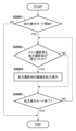
●拡大撮影領域の設定方法
次に、本第1の実施形態における拡大撮影領域の設定方法について説明する。図2Aは、ユーザが拡大撮影領域をそれぞれ指定して登録する個別登録処理のフローチャート、図2Bは、登録モードが設定されている間に撮影された複数の画像の履歴から自動的に拡大撮影領域を登録する履歴登録処理のフローチャートである。
●Method for Setting Enlarged Shooting Area Next, a method for setting an enlarged shooting area in the first embodiment will be described. FIG. 2A is a flowchart of individual registration processing in which a user designates and registers an enlarged imaging area, and FIG. 10 is a flowchart of history registration processing for registering .
まず、図2Aを参照して、個別登録処理について詳しく説明する。S201において、ユーザが、拡大撮影領域を登録するために、操作部115から拡大撮影領域の個別登録処理を行う個別登録モードを選択すると処理が開始され、次のS202に進む。
First, the individual registration process will be described in detail with reference to FIG. 2A. In S201, when the user selects an individual registration mode for performing individual registration processing of the enlarged imaging area from the
S202において、ユーザは、構図を決めた上で、実際の撮影と同様に操作部115の一部であるシャッターボタンを押して撮影を行い、S203に進む。
In S202, the user determines the composition, presses the shutter button, which is a part of the
S203で、S202で撮影された画像データ及び撮影情報は、画像処理部104、CPU114等を介して最終的に記録メディア制御部110により記録メディア111に記録され、拡大撮影領域として登録される。S203で拡大撮影領域の登録が完了すると、処理はS204に進む。なお、ここで記録される撮影情報は、拡大撮影領域を撮影したときの焦点距離、撮影日時、撮影位置を含む。
In S203, the image data and shooting information shot in S202 are finally recorded in the
S204において、ユーザは、個別登録モードを終えるかどうかを判断し、終える場合には、拡大撮影領域の個別登録処理を終了し、拡大撮影領域の登録処理を終了する。一方、拡大撮影領域の登録を続けたい場合は、S202、S203を繰り返し、拡大撮影領域の登録を続ける。なお、拡大撮影領域の登録数は、システム的な上限数以下でユーザが自由に決定できるものとする。 In S204, the user determines whether or not to end the individual registration mode, and if it ends, ends the individual registration processing of the enlarged photographing area, and ends the registration processing of the enlarged photographing area. On the other hand, if the user wants to continue registering the enlarged photographing area, S202 and S203 are repeated to continue registering the enlarged photographing area. It should be noted that the user can freely determine the number of registrations of the magnified photographing areas that is equal to or less than the system upper limit.
次に、図2Bを参照して、履歴登録処理について詳しく説明する。S221において、ユーザは、通常通り、任意の設定および構図で目的の被写体を撮影する。撮影が完了すると、処理はS222に進む。 Next, the history registration process will be described in detail with reference to FIG. 2B. In S221, the user shoots the target subject with arbitrary settings and composition as usual. When the shooting is completed, the process proceeds to S222.
S222においてCPU114は、ユーザによる操作部115の操作により、撮影履歴に基づいて拡大撮影領域を登録する履歴登録モードが設定されているか否かを判定する。履歴登録モードが設定されている場合、処理はS223に進み、設定されていない場合は、そのまま処理を終了する。
In S<b>222 , the
S223で、S221で撮影された画像データ及び撮影情報は、通常の撮影データとして記録メディア111に記録されると共に、S203と同様に、さらに拡大撮影領域として登録される。S223で拡大撮影領域の登録が完了すると、履歴登録処理を終了する。
In S223, the image data and shooting information shot in S221 are recorded in the
●拡大撮影枠の表示方法
次に、第1の実施形態において、図2A及び図2Bを参照して上述した様にして登録された拡大撮影領域を示す拡大撮影枠を、表示部113に表示されたライブビュー画像内の対応する位置に重畳表示する表示処理について、図2Cを参照して詳細に説明する。
Display method of enlarged photographing frame Next, in the first embodiment, the enlarged photographing frame indicating the enlarged photographing area registered as described above with reference to FIGS. 2A and 2B is displayed on the
S231でCPU114は、上述した個別登録処理及び履歴登録処理により登録された全ての拡大撮影領域を示す拡大撮影枠を表示する設定になっているか否かを判定する。全ての拡大撮影領域に対応する拡大撮影枠を表示する設定になっている場合、処理はS233に進み、そうで無ければ、S232に進む。
In S231, the
S232でCPU114は、個別登録処理により登録された拡大撮影領域に対応する拡大撮影枠のみを表示する設定になっているか否かを判定する。個別登録処理により登録された拡大撮影枠のみを表示する設定になっている場合、処理はS234に進み、そうで無ければS235に進む。
In S232, the
S233でCPU114は、記録メディア制御部110に対して指示を出し、個別登録処理で登録された拡大撮影領域と、履歴登録処理で登録された拡大撮影領域両方の、画像データ及び撮影情報を記録メディア111から読み出す。そして、読み出した画像データ及び撮影情報を、メモリ制御部106を介してDRAM107上に展開する。
In S233, the
なお、個別登録処理により登録された画像データ及び撮影情報の読み出し数は、登録時にユーザにより決定された登録数となる。また、履歴登録処理により登録された画像データ及び撮影情報の読み出し数は、予め設定された拡大撮影領域の表示上限数、撮影日時情報、撮影位置情報等に基づいて決定される。例えば、拡大撮影枠の表示上限数だけ最新の撮影履歴から読み出したり、撮影日時情報が撮影日当日のもの且つ撮影位置情報が現在の位置情報から所定範囲内のものを、拡大撮影枠の表示上限数だけ読み出したりといった方法がある。 Note that the number of readouts of image data and photographing information registered by the individual registration process is the number of registrations determined by the user at the time of registration. The number of readouts of the image data and shooting information registered by the history registration process is determined based on the preset display upper limit number of enlarged shooting areas, shooting date/time information, shooting position information, and the like. For example, the latest shooting history is read by the maximum display number of the enlarged shooting frame, or the shooting date and time information of the shooting date and the shooting location information within a predetermined range from the current location information are read out from the shooting history to the display upper limit of the enlarged shooting frame. There is a method such as reading only the number.
個別登録処理により登録された拡大撮影領域と、履歴登録処理により登録された拡大撮影領域の画像データ及び撮影情報の読み出し処理が完了すると、処理はS236に進む。 When the reading process of the enlarged photographing area registered by the individual registration process and the image data and photographing information of the enlarged photographing area registered by the history registration process is completed, the process proceeds to S236.
一方、S234においてCPU114は、記録メディア制御部110に対して指示を出し、個別登録処理により登録された拡大撮影領域の画像データ及び撮影情報をS233と同様に記録メディア111から読み出す。そして、読み出した画像データ及び撮影情報を、メモリ制御部106を介してDRAM107上に展開する。個別登録処理により登録された拡大撮影領域の画像データ及び撮影情報の読み出し処理が完了すると、処理はS236に進む。
On the other hand, in S234, the
また、S235ではCPU114は、記録メディア制御部110に対して指示を出し、履歴登録処理により登録された拡大撮影領域の画像データ及び撮影情報をS233と同様に記録メディア111から読み出す。そして、読み出した画像データ及び撮影情報を、メモリ制御部106を介してDRAM107上に展開する。履歴登録処理により登録された拡大撮影領域の画像データ及び撮影情報の読み出し処理が完了すると、処理はS236に進む。
Also, in S235, the
S236でCPU114(サイズ決定手段)は、S233、S234、S235のいずれかで読み出された拡大撮影領域の撮影情報に含まれる焦点距離情報と、ライブビュー画像を撮影している現在の焦点距離情報に基づいて、拡大撮影枠の表示サイズを算出する。より具体的には、CPU114は、拡大撮影領域の焦点距離と現在の焦点距離の比率を画角換算し、ライブビュー画像における拡大撮影枠の表示サイズを決定する。拡大撮影枠の表示サイズの算出が完了すると、処理はS237に進む。
In S236, the CPU 114 (size determining means) determines the focal length information included in the imaging information of the enlarged imaging area read out in any of S233, S234, or S235, and the current focal length information in which the live view image is being shot. , the display size of the enlarged photographing frame is calculated. More specifically, the
S237で画像処理部104(位置決定手段)は、S233、S234、S235のいずれかで読み出された拡大撮影領域の画像データと、ライブビュー画像データに基づいて、拡大撮影枠の表示位置を検出する。拡大撮影枠の表示位置の検出は、ライブビュー画像データから拡大撮影領域の画像データに対応する領域を検出することで行われ、例えば画像データのテンプレートマッチング処理を行う方法がある。 In S237, the image processing unit 104 (position determination unit) detects the display position of the enlarged shooting frame based on the image data of the enlarged shooting area read out in any one of S233, S234, and S235 and the live view image data. do. Detection of the display position of the enlarged shooting frame is performed by detecting an area corresponding to the image data of the enlarged shooting area from the live view image data. For example, there is a method of performing template matching processing of the image data.
テンプレートマッチングでは、まずS236で算出されたライブビュー画像に対する画角比率に基づいて、拡大撮影領域の画像データをリサイズしする。次に、リサイズした拡大撮影領域の画像データを原画像、ライブビュー画像データを参照画像とし、原画像をテンプレートブロックとし、参照画像の各位置においてテンプレートブロック内の画素値の分布との相関を求める。このとき、参照画像中で最も相関が高くなる位置がテンプレートブロックの対応位置であり、ライブビュー画像内における拡大撮影枠の表示位置となる。また、拡大撮影領域の全領域が必ずしもライブビュー画像内に含まれている必要はない。拡大撮影領域の一部領域がライブビュー画像内に含まれるような状態もS237の処理では検出可能としてもよい。拡大撮影枠の表示位置の検出が完了すると、処理はS238に進む。 In template matching, first, the image data of the enlarged imaging area is resized based on the angle of view ratio to the live view image calculated in S236. Next, the image data of the resized enlarged shooting area is used as the original image, the live view image data is used as the reference image, the original image is used as the template block, and the correlation with the pixel value distribution within the template block is obtained at each position of the reference image. . At this time, the position where the correlation is highest in the reference image is the corresponding position of the template block, and is the display position of the enlarged shooting frame in the live view image. Also, the entire area of the enlarged imaging area does not necessarily have to be included in the live view image. A state in which a partial area of the enlarged imaging area is included in the live view image may also be detected in the processing of S237. When the detection of the display position of the enlarged photographing frame is completed, the process proceeds to S238.
S238でCPU114は、ライブビュー画像内に拡大撮影枠の表示位置が検出されたか否かの判定を行う。S237の処理で画像処理部104によって出力される検出結果はテンプレートマッチングによる相関値が最も高い結果であるため、実際には対応する位置が存在しない場合でも出力されてしまう。このため、CPU114は、例えば、S238の処理で画像処理部104によって出力される相関値に対して閾値処理等を行い、信頼性の高い結果が得られた場合に、ライブビュー画像内に拡大撮影枠の表示位置が検出されたと判定する。ライブビュー画像内に拡大撮影枠の表示位置が検出された場合、処理はS239に進み、検出されなかった場合はS240に進む。
In S238, the
S239でCPU114は、表示制御部112に対して指示を出し、S238で判定された、ライブビュー画像内に表示可能な拡大撮影枠をライブビュー画像に重畳して表示部113に表示する。
In S<b>239 , the
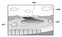
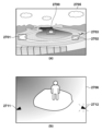
ここで、図3を参照して、拡大撮影枠の表示状態について説明する。図3は、ライブビュー画像に拡大撮影枠を表示した場合の表示例を示す模式図である。図3(a)は、表示部113に表示される広角端で撮像されたライブビュー画像300を示している。図3(b)及び(c)は、被写体が存在しない状態で予め個別登録処理により撮影して拡大撮影領域として登録した画像の一例を示す。これらの登録画像に基づいて、図3(a)のライブビュー画像300にはそれぞれに対応する拡大撮影枠301,302が表示される。
Here, the display state of the enlarged photographing frame will be described with reference to FIG. FIG. 3 is a schematic diagram showing a display example when an enlarged photographing frame is displayed in a live view image. FIG. 3A shows a
一方、図3(d)及び(e)は、履歴登録モード設定時に、ユーザによる通常撮影によって記録されている画像の一例を示している。これらの画像が拡大撮影領域として登録されていた場合、これらの画像に基づいて、図3(a)のライブビュー画像300にはそれぞれ対応する拡大撮影枠301,302が表示されることになる。
On the other hand, FIGS. 3(d) and 3(e) show an example of an image recorded by normal photography by the user when the history registration mode is set. If these images are registered as enlarged photographing areas, corresponding enlarged photographing
また、図3(b)に示す画像を拡大撮影領域としてユーザが個別登録し、図3(e)に示す画像が拡大撮影領域として履歴登録されていた場合も同様に、ライブビュー画像300には、それぞれ対応する拡大撮影枠301,302が表示されることになる。
Similarly, when the user individually registers the image shown in FIG. 3B as an enlarged photographing area and the image shown in FIG. , corresponding enlarged photographing
S239で、拡大撮影枠の表示処理が完了すると、処理はS240に進み、CPU114は、処理対象となっているすべての拡大撮影領域に対して拡大撮影枠の表示処理が完了したか否かを判定する。すべての拡大撮影領域に対して拡大撮影枠の表示処理が完了している場合、処理はS241に進み、すべての拡大撮影領域に対して拡大撮影枠の表示処理が完了していない場合、処理はS236に戻り、S236~S239を繰り返す。
In S239, when the display processing of the enlarged photographing frame is completed, the processing advances to S240, and the
S241でCPU114は、ライブビュー表示が終了したかを判定する。例えば、ユーザにより操作部115の電源スイッチがOFFにされた場合や、記録画像の再生ボタンが操作された場合等は、ライブビュー表示終了と判定し、拡大撮影枠の表示処理を終了する。一方、ライブビュー表示を続ける場合には処理はS231に戻り、S231~S240の処理を繰り返す。
In S241, the
図3(f)及び(g)は、ユーザがズーム倍率を拡大方向に変更している場合に、図2Cに示す表示処理を続けたときの表示例を示す。 FIGS. 3(f) and 3(g) show display examples when the display processing shown in FIG. 2C is continued when the user has changed the zoom magnification in the enlargement direction.
図3(a)に示す状態から、拡大撮影枠302が示す領域の画像を撮影しようとする場合、ユーザは、操作部115に含まれるズーム操作部材によりズーム倍率を高くすると共に、画角を拡大撮影枠302の方に移動させる。図3(f)は、この時に表示されるライブビュー画像の一例を示す。図3(g)は、更にズーム倍率を高くし、画角を拡大撮影枠302の方に移動させた場合に表示されるライブビュー画像の一例を示す。更にズーム倍率を高くしていき、ライブビュー画像の画角と拡大撮影領域が一致した場合には、図3(c)に示す様な画像が表示されることになる。
In the state shown in FIG. 3A, when the user attempts to capture an image of the area indicated by the
また、この状態から次に拡大撮影枠301の領域の画像を撮影したい場合には、一旦、ズーム倍率を低くして図3(a)に示す様に拡大撮影枠301を表示させることで、拡大撮影枠301の領域にスムーズに画角を合わせていくことが可能になる。
Further, when it is desired to photograph an image of the area of the enlarged photographing
以上説明したように、表示装置に表示されたライブビュー画像に、登録された拡大撮影領域に対応する拡大撮影枠をライブビュー画像内の対応する位置に重畳表示することで、広角画像内から望遠での撮影構図を探索する際の指標ができる。これにより、特定の領域の画像を繰り返し望遠撮影するような場合に、撮影構図を探索する時間を短縮することができ、スムーズな構図変更が可能となり、撮影機会の損失の低減につなげることができる。 As described above, by superimposing the enlarged shooting frame corresponding to the registered enlarged shooting area on the live view image displayed on the display device at the corresponding position in the live view image, the wide-angle image can be zoomed into the telephoto range. You can use it as an index when searching for a shooting composition. As a result, when repeatedly telephoto shooting an image of a specific area, the time to search for the shooting composition can be shortened, smooth composition changes are possible, and loss of shooting opportunities can be reduced. .
なお、上述した例では、拡大撮影枠の表示方法として、単写撮影で得られた拡大撮影領域に基づく表示例を説明したが、本発明はこれに限られるものでは無い。例えば、連続撮影モードで撮影された複数の画像を拡大撮影領域として登録した場合に対しては、図4の表示枠401に示すような連続撮影の最初と最後の画像に対応する拡大撮影枠のみ表示し、連続撮影とわかるようなグルーピングを示す表示をしても良い。また、図4の表示枠402に示すような最初と最後の画像に対応する拡大撮影枠に加えて、予め設定された間隔で間引いた複数の拡大撮影枠を表示し、連続撮影と分かるようなグルーピングを示す表示をしても良い。
In the above-described example, as a display method of the enlarged photographing frame, a display example based on the enlarged photographing area obtained by single-shot photographing has been described, but the present invention is not limited to this. For example, when a plurality of images shot in the continuous shooting mode are registered as the enlarged shooting area, only the enlarged shooting frames corresponding to the first and last images of the continuous shooting as shown in the
さらに、連続撮影に限らず、動画撮影で得られた拡大撮影領域を同様な表示で表現しても良い。また、図4の枠403近辺の点線枠で示されるような空間的、もしくは時間軸的に密集した撮影履歴の場合は、すべて表示すると煩雑となるため、重心等を利用して代表的な拡大撮影枠403のみ表示するようにしても良い。
Further, not limited to continuous shooting, an enlarged shooting area obtained by moving image shooting may be displayed in a similar manner. In addition, in the case of shooting histories that are densely spaced or temporally concentrated as indicated by the dotted line frame near the
また、本実施形態ではCPU114が処理を行う例を説明したが、専用のハードウェアで実現してもよい。
Also, in the present embodiment, an example in which the
<第2の実施形態>
次に、本発明の第2の実施形態について説明する。なお、第2の実施形態における撮像装置は、図1を参照して説明したものと同様であるため、ここでは説明を省略する。
<Second embodiment>
Next, a second embodiment of the invention will be described. Note that the image capturing apparatus in the second embodiment is the same as that described with reference to FIG. 1, so description thereof will be omitted here.
●拡大撮影領域の設定方法
図5Aは、第2の実施形態における個別登録処理のフローチャート、図5Bは、第2の実施形態における履歴登録処理のフローチャートである。なお、図5A及び図5Bにおいて、図2A及び図2Bと同じ処理には同じステップ番号を付して説明を省略する。
●Method for Setting Enlarged Shooting Area FIG. 5A is a flowchart of individual registration processing in the second embodiment, and FIG. 5B is a flowchart of history registration processing in the second embodiment. In addition, in FIGS. 5A and 5B, the same step numbers are given to the same processes as in FIGS. 2A and 2B, and the description thereof is omitted.
図5Aにおける処理と、図2Aにおける処理との違いは、図2AのS203においては拡大撮影領域の画像データ及び撮影情報を登録するのに対し、第2の実施形態ではS501において、更に、撮影条件を登録する点である。 The difference between the processing in FIG. 5A and the processing in FIG. 2A is that the image data of the enlarged imaging area and the imaging information are registered in S203 of FIG. is registered.
また、図5Bにおける処理と、図2Bにおける処理との違いは、図2BのS223においては拡大撮影領域の画像データ及び撮影情報を登録するのに対し、第2の実施形態ではS521において、更に、撮影条件を登録する点である。 Also, the difference between the processing in FIG. 5B and the processing in FIG. 2B is that the image data of the enlarged imaging area and the imaging information are registered in S223 of FIG. 2B, whereas in the second embodiment, in S521, The point is that the imaging conditions are registered.
なお、図5A及び図5Bで登録される撮影条件とは、例えば、撮影モード、絞り、露光時間、ISO感度、露出補正、フラッシュ使用の有無、特殊効果フィルタの使用の有無及び種類といった条件である。 Note that the shooting conditions registered in FIGS. 5A and 5B are, for example, shooting mode, aperture, exposure time, ISO sensitivity, exposure compensation, use of flash, use of special effect filter and type. .
●拡大撮影枠の表示方法
次に、第2の実施形態において、図5A及び図5Bに示す様にして登録した拡大撮影領域を示す拡大撮影枠を、表示部113に表示されたライブビュー画像内の対応する位置に重畳表示する表示処理について、図5C及び図5Dを参照して詳細に説明する。
Display Method of Enlarged Shooting Frame Next, in the second embodiment, an enlarged shooting frame indicating an enlarged shooting area registered as shown in FIGS. 5C and 5D, a detailed description will be given of the display processing for superimposing and displaying at the position corresponding to .
図5Cは、図5A及び図5Bに示す様にして登録された拡大撮影領域の拡大撮影枠を表示し、登録されている撮影条件を現在の撮影条件に設定する処理を示すフローチャートである。なお、図5Cにおいて、図2Cと同様の処理には同じ参照番号を付して、説明を省略する。 FIG. 5C is a flowchart showing processing for displaying an enlarged imaging frame of an enlarged imaging area registered as shown in FIGS. 5A and 5B and setting the registered imaging conditions as the current imaging conditions. In addition, in FIG. 5C, the same reference numerals are assigned to the same processes as in FIG. 2C, and the description thereof is omitted.
まず、S231~S240において、図2Cを参照して第1の実施形態で説明した拡大撮影枠の表示処理を行う。拡大撮影枠の表示処理が完了すると、処理はS532に進む。S532では、拡大撮影枠と現在の撮影領域であるライブビュー画像の位置関係を明示的に表現するための基準点を表示する処理を行う。 First, in S231 to S240, the processing for displaying the enlarged photographing frame described in the first embodiment with reference to FIG. 2C is performed. When the processing for displaying the enlarged photographing frame is completed, the processing advances to S532. In S532, a process of displaying a reference point for explicitly expressing the positional relationship between the enlarged shooting frame and the live view image, which is the current shooting area, is performed.
図5Dは、S532で行われる基準点を表示するための基準点表示処理のフローチャートである。基準点表示処理が開始されると、S541でCPU114は、基準点としてAF枠を使用する設定になっているか否かを判定する。基準点としてAF枠を使用する設定の場合、処理はS542に進む。一方で、基準点としてAF枠を使用しない設定の場合、処理はS543に進む。なお、ここで使用するAF枠は、表示部113の表示画面上の指定された位置に、表示部113に表示されるライブビュー画像の表示内容とは無関係に設定される。
FIG. 5D is a flow chart of the reference point display process for displaying the reference points performed in S532. When the reference point display process is started, in S541, the
S542でCPU114は更に、AF領域に、例えば自動選択などの特定領域指定などの指定があるか否かを判定する。AF領域に指定がある場合、処理はS544に進み、指定がされていない場合、処理はS543に進む。S543でCPU114は、基準点としてAF枠を使用する設定になっていない場合、もしくはAF領域に特に指定がない場合に、現在の撮影領域であるライブビュー画像の基準点を光学中心位置とし、基準点を示すシンボルを表示する。基準点を示すシンボルは、例えば、十字マークや丸点などである。
In S542, the
一方、S544でCPU114は、指定されたAF領域が現在の撮影領域であるライブビュー画像において、ユーザが主要被写体を配置しようと考えている領域として判断し、指定されたAF領域を示すAF枠を基準点として表示する。基準点の表示処理を行うと基準点表示処理は終了し、処理は図5CのS533に進む。
On the other hand, in S544, the
S533では、ユーザがデジタルカメラ100の向きを操作してフレーミングを変更したかどうかを判断し、変更しなかった場合にはS241に進み、変更した場合にはS534に進む。
In S533, it is determined whether or not the user has changed the framing by operating the direction of the
S534でCPU114は、基準点と拡大撮影枠が所定範囲内まで近接しているかどうかを判定する。予め決めておいた所定範囲内まで接近したと判定された場合、処理はS535に進み、所定範囲内まで近接していないと判定された場合、処理はS241に進む。
In S534, the
S535でCPU114は、基準点に近接した拡大撮影枠に対応する拡大撮影領域に登録されている撮影条件を、現在の撮影条件として設定する。撮影条件の設定を行うとS241に進み、ライブビュー表示が終了するまで、上述した処理を繰り返す。
In S535, the
図6は、ライブビュー画像300に、拡大撮影枠301,302及び基準点601を表示した場合の表示例と、対応する撮影条件を表す模式図である。
FIG. 6 is a schematic diagram showing a display example when the enlarged shooting frames 301 and 302 and the
図6(b)及び(c)は、それぞれ図6(a)のライブビュー画像上に表示されている拡大撮影枠301,302に対応する拡大撮影領域の画像であり、本実施形態では上述したような撮影条件も共に拡大撮影領域の情報として登録されている。フレーミングの変更により拡大撮影枠301または302と、基準点601とが接近すると、図6(b)または(c)に示す撮影条件が現在の撮影条件として設定される。
FIGS. 6B and 6C are images of enlarged photographing areas corresponding to the enlarged photographing
以上説明したように、拡大撮影領域の登録時に撮影条件も合わせて登録を行う。そして、現在の撮影領域の基準点と拡大撮影枠が所定範囲内まで接近した場合に、対応する拡大撮影領域の撮影条件を現在の撮影条件として設定することで、構図変更から撮影までの時間をより短縮することが可能となる。 As described above, the imaging conditions are also registered when registering the enlarged imaging area. When the reference point of the current shooting area and the enlarged shooting frame come close to each other within a predetermined range, the shooting conditions of the corresponding enlarged shooting area are set as the current shooting conditions. It is possible to shorten it further.
<第3の実施形態>
次に、本発明の第3の実施形態について説明する。なお、第3の実施形態における撮像装置は、図1を参照して説明したものと同様であるため、ここでは説明を省略する。また、第3の実施形態おいて、拡大撮影領域を登録する処理は、第1の実施形態において図2A及び図2B、または、第2の実施形態において図5A及び図5Bを参照して説明した処理と同様であるため、説明を省略する。
<Third Embodiment>
Next, a third embodiment of the invention will be described. Note that the imaging apparatus according to the third embodiment is the same as that described with reference to FIG. 1, and therefore description thereof is omitted here. Also, in the third embodiment, the process of registering the enlarged imaging area has been described with reference to FIGS. 2A and 2B in the first embodiment or FIGS. 5A and 5B in the second embodiment. Since it is the same as the processing, the description is omitted.
●拡大撮影枠の表示方法
次に、本第3の実施形態において、拡大撮影枠を表示部113に表示されたライブビュー画像内の対応する位置に重畳表示する表示処理について、図7及び図8を参照して詳細に説明する。
Display Method of Enlarged Shooting Frame Next, in the third embodiment, display processing for superimposing and displaying an enlarged shooting frame at a corresponding position in the live view image displayed on the
なお、本第3の実施形態では、第2の実施形態で図5C及び図5Dを参照して説明した拡大撮影枠及び基準点の表示処理が、例えば、ライビュー画像を取得する毎等の所定周期で繰り返し行われているものとする。ただし、S533~S535の処理に関しては、図2A及び図2Bで説明したような撮影条件が登録されていない場合には、行わない。 Note that, in the third embodiment, the processing for displaying the enlarged shooting frame and the reference point described in the second embodiment with reference to FIGS. It is assumed that the However, the processing of S533 to S535 is not performed if the imaging conditions described with reference to FIGS. 2A and 2B are not registered.
まず、図7のS701においてCPU114は、操作部115の操作により拡大撮影領域の拡大表示モードが指示されたかどうかを判断する。拡大表示モードが指示されていなければ、処理を終了する。この場合、例えば、図8(a)及び図8(b)に示す様な画像が表示される。なお、図8(a)及び図8(b)において、801は基準点、802は拡大撮影枠を示している。拡大表示モードが指示されると、S702に進む。
First, in S701 of FIG. 7, the
S702でCPU114は、基準点と拡大撮影枠との最短距離が予め決めておいた所定範囲内であるかどうかを判定する。ここでは、基準点と拡大撮影枠との最短距離をライブビュー画像の画面内の表示位置座標から計算し、所定範囲との比較を行う。所定範囲内である場合には、S703へ移行する。
In S702, the
図8(b)は、図8(a)の状態からデジタルカメラ100が右方向にパン動作され、基準点801と拡大撮影枠802との距離が近づき、S702において所定範囲内であると判定される直前の状態を示している。
In FIG. 8B, the
S703では、拡大撮影枠内の画像を、ライブビュー画面内で拡大表示する。図8(c)は、図8(b)に示す状態から、拡大撮影枠802内の画像を拡大表示した場合の表示例を示す。803は、拡大撮影枠802内の画像を拡大した部分画像を示している。なお、ここでは、電子ズームによる拡大処理を行う。
In S703, the image within the enlarged shooting frame is enlarged and displayed within the live view screen. FIG. 8(c) shows a display example when the image within the enlarged photographing
一方、S702で所定範囲内ではないと判定された場合には、拡大撮影枠内の画像の拡大表示は行わずに、そのままS705に遷移する。 On the other hand, if it is determined in S702 that it is not within the predetermined range, the process proceeds directly to S705 without enlarging and displaying the image within the enlarged imaging frame.
続くS705では、拡大表示モードが終了したかを判定し、ユーザによる操作部115の操作により拡大表示モードが終了していれば、処理を終了し、拡大表示モードが終了していなければ、再度S702の処理に戻る。 In subsequent S705, it is determined whether or not the enlarged display mode has ended. return to the process of
上記の通り第3の実施形態によれば、ライブビュー画像において、拡大撮影枠の画像を拡大表示することにより、拡大表示領域で得られる画像を確認し易くすることができる。 As described above, according to the third embodiment, it is possible to easily check the image obtained in the enlarged display area by enlarging and displaying the image of the enlarged shooting frame in the live view image.
なお、図8に示す例では、基準点として光学中心位置を表示しているが、図5Dを参照して説明したように、AF枠を表示するようにしても同様の効果を得ることができる。また、基準点801と拡大撮影枠802の距離が所定範囲内であるかを判定しているが、重なった場合を判定条件にしても良い。
Although the optical center position is displayed as the reference point in the example shown in FIG. 8, the same effect can be obtained by displaying the AF frame as described with reference to FIG. 5D. . Also, although it is determined whether the distance between the
また、上述した例では、操作部115により拡大表示モードが設定されている場合に、拡大撮影枠802の画像を拡大表示するものとして説明したが、基準点801と拡大撮影枠802の距離が所定範囲内である場合に、常に拡大表示する制御にしても良い。
Further, in the above example, when the enlarged display mode is set by the
また、拡大表示としては、図8(c)のような表示画面上の一部領域にではなく、全画面に拡大表示しても良い。また、拡大表示の際に、拡大撮影枠802の撮影条件に特殊処理モードの画像処理が設定されていれば、特殊処理した画像を拡大表示しても良い。例えば、特殊処理モードとして、モノクロ撮影モードが撮影条件として設定されていた場合には、モノクロ画像処理を施した、拡大撮影枠802の画像を拡大表示する。
Moreover, as the enlarged display, the enlarged display may be performed on the entire screen instead of the partial area on the display screen as shown in FIG. 8(c). Also, when displaying an enlarged image, if the image processing in the special processing mode is set as the imaging condition of the
さらに、拡大表示を行う際に、撮像素子102からの読み出し方法を、解像度が高くなるように変更してもよい。例えば、拡大表示前は撮像素子102内で隣接画素値を加算後に読み出し、拡大表示時は、拡大撮影枠802内の画像の各画素値を一画素ずつ加算せずに読み出す方式に変更してもよい。
Furthermore, when performing enlarged display, the reading method from the
<第4の実施形態>
次に、本発明の第4の実施形態について説明する。なお、第4の実施形態における撮像装置は、図1を参照して説明したものと同様であるため、ここでは説明を省略する。また、第4の実施形態おいて、拡大撮影領域を登録する処理は、第1の実施形態において図2A及び図2B、または、第2の実施形態において図5A及び図5Bを参照して説明した処理と同様であるため、説明を省略する。
<Fourth Embodiment>
Next, a fourth embodiment of the invention will be described. Note that the image capturing apparatus according to the fourth embodiment is the same as that described with reference to FIG. 1, so description thereof will be omitted here. Further, in the fourth embodiment, the process of registering the enlarged imaging area has been described with reference to FIGS. 2A and 2B in the first embodiment or FIGS. 5A and 5B in the second embodiment. Since it is the same as the processing, the description is omitted.
●画角制御
次に、本第4の実施形態における、表示部113のライブビュー画像内に表示された拡大撮影枠を利用した画角制御について、図9及び図10を参照して詳細に説明する。
Angle of View Control Next, the angle of view control using the enlarged shooting frame displayed in the live view image of the
なお、本第4の実施形態では、第2の実施形態で図5C及び図5Dを参照して説明した拡大撮影枠及び基準点の表示処理が、例えば、ライビュー画像を取得する毎等の所定周期で繰り返し行われているものとする。ただし、S533~S535の処理に関しては、図2A及び図2Bで説明したような撮影条件が登録されていない場合には、行わない。 Note that, in the fourth embodiment, the processing for displaying the enlarged shooting frame and the reference point described in the second embodiment with reference to FIG. 5C and FIG. It is assumed that the However, the processing of S533 to S535 is not performed if the imaging conditions described with reference to FIGS. 2A and 2B are not registered.
まず、図9のS901においてCPU114は、操作部115の操作によりズームモードが指示されたかどうかを判断する。ズームモードが指示されていなければ、処理を終了する。この場合、例えば、図10(a)及び図10(b)に示す様な画像が表示される。図10(a)及び図10(b)において、1001は基準点、1002は拡大撮影枠を示している。ズームモードが指示されると、S902に進む。
First, in S<b>901 of FIG. 9 , the
S902でCPU114は、基準点と拡大撮影枠が重なったかどうかを判定する。ここでは、基準点及び拡大撮影枠のライブビュー画像における表示位置座標から、重なったかどうかの判定を行う。重なっていなければ処理を終了し、重なっていれば、S903に進む。
In S902, the
図10(b)は、図10(a)の状態からデジタルカメラ100が右方向にパン動作され、基準点1001と拡大撮影枠1002が重なったと判定される直前の状態を示している。
FIG. 10B shows a state immediately before it is determined that the
S903では、拡大撮影枠1002に対応する拡大撮影領域の撮影情報に基づいて、結像光学部101に含まれるズームレンズの位置を登録されている焦点距離まで駆動してズーム倍率を上げる。図10(c)は、図10(b)の基準点1001を中心にズームして得られた画像の一例を示す図である。続くS904で、ズームモードが終了したかどうかを判断し、終了していなければS902に戻り、終了された場合には、処理を終了する。
In S903, the position of the zoom lens included in the imaging
上記の通り第4の実施形態によれば、第1の実施形態と同様の効果に加え、更に、撮影構図を変更する時間を短縮することができる。 As described above, according to the fourth embodiment, in addition to the same effect as the first embodiment, it is possible to shorten the time required to change the photographing composition.
なお、図10では、基準点として光学中心位置を表示しているが、図5Dを参照して説明したように、AF枠を表示するようにしても同様の効果を得ることができる。また、S902では、基準点1001と拡大撮影枠1002が重なった場合を判定条件としているが、基準点1001と拡大撮影枠1002との最短距離が所定範囲内であるかを判定条件にしても良い。
Although the optical center position is displayed as the reference point in FIG. 10, the same effect can be obtained by displaying the AF frame as described with reference to FIG. 5D. In S902, the determination condition is that the
また、上述した例では、操作部115によりズームモードが設定されている場合に、焦点距離を変更するものとして説明したが、基準点1001と拡大撮影枠1002が重なった場合に、常に焦点距離を変更するように制御にしても良い。
Further, in the above example, the focal length is changed when the zoom mode is set by the
なお、ズームの方法としては、ズームレンズを駆動する光学ズームの代わりに、電子ズームを実施しても良い。 As a zooming method, electronic zooming may be performed instead of optical zooming that drives a zoom lens.
<第5の実施形態>
次に、本発明の第5の実施形態について説明する。なお、第5の実施形態における撮像装置は、図1を参照して説明したものと同様であるため、ここでは説明を省略する。また、第5の実施形態おいて拡大撮影領域を登録する処理は、第1の実施形態において図2A及び図2B、または、第2の実施形態において図5A及び図5Bを参照して説明した処理と同様であるため、説明を省略する。
<Fifth Embodiment>
Next, a fifth embodiment of the invention will be described. Note that the image capturing apparatus according to the fifth embodiment is the same as that described with reference to FIG. 1, so description thereof will be omitted here. Further, the process of registering the enlarged imaging area in the fifth embodiment is the process described with reference to FIGS. 2A and 2B in the first embodiment, or the process described with reference to FIGS. 5A and 5B in the second embodiment. , so the description is omitted.
●画角制御
次に、本第5の実施形態における、表示部113のライブビュー画像内に表示された拡大撮影枠を利用した画角制御について、図11及び図12を参照して詳細に説明する。
Angle of View Control Next, the angle of view control using the enlarged shooting frame displayed in the live view image of the
なお、本第5の実施形態では、第1の実施形態で図2Cを参照して説明した拡大撮影枠の表示処理、または、第2の実施形態で図5C及び図5Dを参照して説明した拡大撮影枠及び基準点の表示処理が、例えば、ライビュー画像を取得する毎等の所定周期で繰り返し行われているものとする。ただし、S533~S535の処理に関しては、図2A及び図2Bで説明したような撮影条件が登録されていない場合には、行わない。 In addition, in the fifth embodiment, the display processing of the enlarged photographing frame described with reference to FIG. 2C in the first embodiment or the processing described with reference to FIGS. 5C and 5D in the second embodiment It is assumed that the process of displaying the enlarged photographing frame and the reference point is repeatedly performed at predetermined intervals, such as each time a live-view image is obtained. However, the processing of S533 to S535 is not performed if the imaging conditions described with reference to FIGS. 2A and 2B are not registered.
まず、図11のS1101においてCPU114は、操作部115の操作によりズームモードが指示されたかどうかを判断する。ズームモードが指示されていなければ、この処理を終了する。ズームモードが指示されると、S1102に進む。
First, in S<b>1101 of FIG. 11 , the
S1102においてCPU114は、拡大撮影枠1202がライブビュー画像の画角内に内包される焦点距離まで、結像光学部101に含まれるズームレンズを駆動してズーム動作を実施する。続くS1103では、ユーザの操作などにより、デジタルカメラ100の向きが操作されてフレーミングが変更されたかを判定する。変更された場合には、S1102の処理に戻って、ズーム動作を実施する。
In S1102, the
図12(b)は、図12(a)に示す状態からデジタルカメラ100が右方向にパン動作され、拡大撮影枠1202が画面中央(光学中心1201)に近づき、拡大撮影枠1202が撮像素子102の画角内に内包される焦点距離までズーム動作を実施したときに表示される画像を示す模式図である。このように、拡大撮影枠1202が光学中心1201に近づくにつれて、拡大撮影枠1202が撮像素子102の画角内に内包される焦点距離まで段階的にズーム動作が実施される。そして、拡大撮影枠1202と撮像素子102の画角が一致すると、図12(c)の様な画像が表示されることになる。
In FIG. 12B, the
一方、S1103で、フレーミングが変更されなかったと判定された場合にはS1104に遷移する。続くS1104で、ズームモードが終了した場合には処理を終了し、ズームモードを終了しない場合には、S1103の処理へ遷移する。
On the other hand, if it is determined in S1103 that the framing has not been changed, the process proceeds to S1104. In subsequent S1104, if the zoom mode has ended, the process ends, and if the zoom mode has not ended, the process proceeds to S1103.
上記の通り本第5の実施形態によれば、第1の実施形態と同様の効果に加え、更に、撮影構図を変更する時間を短縮することができる。 As described above, according to the fifth embodiment, in addition to the same effect as the first embodiment, it is possible to shorten the time required to change the photographing composition.
なお、ズームの方法としては、ズームレンズを駆動する光学ズームの代わりに、電子ズームを実施しても良い。 As a zooming method, electronic zooming may be performed instead of optical zooming that drives a zoom lens.
<第6の実施形態>
次に、本発明の第6の実施形態について説明する。なお、第6の実施形態における撮像装置は、図1を参照して説明したものと同様であるため、ここでは説明を省略する。また、第6の実施形態おいて拡大撮影領域を登録する処理は、第1の実施形態において図2A及び図2B、または、第2の実施形態において図5A及び図5Bを参照して説明した処理と同様であるため、説明を省略する。
<Sixth Embodiment>
Next, a sixth embodiment of the invention will be described. Note that the imaging apparatus according to the sixth embodiment is the same as that described with reference to FIG. 1, so description thereof will be omitted here. Further, the process of registering the enlarged imaging area in the sixth embodiment is the process described with reference to FIGS. 2A and 2B in the first embodiment, or the process described with reference to FIGS. 5A and 5B in the second embodiment. , so the description is omitted.
●画角制御
次に、本第6の実施形態における、表示部113のライブビュー画像内に表示された拡大撮影枠を利用した画角制御について、図13及び図14を参照して詳細に説明する。
Angle of View Control Next, the angle of view control using the enlarged shooting frame displayed in the live view image of the
なお、本第6の実施形態では、第1の実施形態で図2Cを参照して説明した拡大撮影枠の表示処理、または、第2の実施形態で図5C及び図5Dを参照して説明した拡大撮影枠及び基準点の表示処理が、例えば、ライビュー画像を取得する毎等の所定周期で繰り返し行われているものとする。ただし、S533~S535の処理に関しては、図2A及び図2Bで説明したような撮影条件が登録されていない場合には、行わない。 Note that in the sixth embodiment, the display processing of the enlarged photographing frame described with reference to FIG. 2C in the first embodiment, or the processing described with reference to FIGS. 5C and 5D in the second embodiment. It is assumed that the process of displaying the enlarged photographing frame and the reference point is repeatedly performed at predetermined intervals, such as each time a live-view image is obtained. However, the processing of S533 to S535 is not performed if the imaging conditions described with reference to FIGS. 2A and 2B are not registered.
まず、図13のS1301においてCPU114は、操作部115の操作ボタンの押下により、フレーミングアシストが指示されたかどうかを判定する。フレーミングアシストが指示されていなければ、この処理を終了する。フレーミングアシストが指示されると、S1303に進む。なお、本第6の実施形態において、S1302でフレーミングアシストが指示される直前の画像は、一例として、図14(a)に示されるように、デジタルカメラ100で、望遠画角にて人物1402を撮影しているものとする。また、図14(a)に示す画像の画角は、拡大撮影領域として登録されているものとする。
First, in S<b>1301 of FIG. 13 , the
フレーミングアシストが指示されると、S1303において、所定の広角側の焦点距離まで自動的に結像光学部101に含まれるズームレンズを駆動して、ズームアウト動作を実施する。図14(b)は、フレーミングアシストが実施され、ズームアウト後の広角画角となり、さらにデジタルカメラ100の撮影範囲が右方向にパンされた時に表示される画像の一例を示す。図14(b)において、点線枠1412は、目安としてフレーミングアシスト前の焦点距離の画角を光学中心位置に表示したものである。また、図14(a)に示す拡大撮影領域に対応する拡大撮影枠1411が表示される。
When the framing assist is instructed, in S1303, the zoom lens included in the imaging
次に、S1304では、操作部115の操作ボタンが放されたことにより、フレーミングアシストが解除されたかどうかを判定する。解除された場合はS1305に遷移し、解除されない場合にはS1303の処理を繰り返す。
Next, in S1304, it is determined whether or not the framing assist has been canceled by releasing the operation button of the
S1305では、拡大撮影枠1411が画角内に内包される焦点距離まで自動的に結像光学部101に含まれるズームレンズを駆動して、ズームイン動作を実施する。図14(c)は、図14(b)に示す状態から、フレーミングアシストが解除された後に、拡大撮影枠1411が画角内に内包される焦点距離までズームイン動作が実施された場合に表示される画像の一例を示す図である。
In S1305, the zoom lens included in the imaging
次のS1307では、デジタルカメラ100の向きを操作してフレーミングを変更したかどうかを判断する。変更した場合にはS1308に遷移し、変更しなかった場合にはS1307の処理を繰り返す。
In the next step S1307, it is determined whether or not the orientation of the
S1308では、拡大撮影枠1411が画角内に収まっているかを判定し、収まっている場合には、S1305に遷移する。一方、収まっていないと判定された場合にはS1309に遷移し、画角内に拡大撮影領域の方向を表示する。図14(d)は、人物1404を望遠で撮影し、表示部113にライブビュー表示している場合の画像の一例を示す図で、画角外にある拡大撮影枠1411の方向を示すアイコン1420を表示している。なお、S1309における拡大撮影枠1411の方向を示すアイコン1420を示す処理は、行わなくても構わない。
In S1308, it is determined whether the enlarged photographing
S1309の処理を終えると、本処理を終了する。 After finishing the processing of S1309, this processing ends.
上記の通り本第6の実施形態によれば、第1の実施形態と同様の効果に加え、望遠撮影時に被写体を見失った際などに、広角画角にすることにより、被写体を再度画角内に捕捉し直すことが容易になる。 As described above, according to the sixth embodiment, in addition to the same effect as the first embodiment, when the subject is lost during telephoto shooting, the subject can be relocated within the angle of view by changing the angle of view to a wide angle. It becomes easier to recapture the
なお、本実施形態では、拡大撮影領域が一つである例を用いて説明したが、複数存在する場合にも適用が可能である。例えば、S1305では全ての拡大撮影枠が画角内に内包される、または、直前に撮影した拡大撮影領域など特定の拡大撮影領域の拡大撮影枠が画角内に内包されるようにズームイン動作を行えばよい。そして、S1309において、画角外の全ての拡大撮影領域の方向を示すアイコンの表示を行う、または、直前に撮影した拡大撮影領域など特定の画角外の拡大撮影領域方向を示すアイコンの表示を行えばよい。 In this embodiment, an example in which there is one magnified imaging area has been described, but application is also possible when there are a plurality of magnified imaging areas. For example, in S1305, the zoom-in operation is performed so that all the enlarged shooting frames are included within the angle of view, or the enlarged shooting frame of a specific enlarged shooting area such as the immediately preceding enlarged shooting area is included within the angle of view. Do it. Then, in step S1309, an icon indicating the direction of all enlarged imaging areas outside the angle of view is displayed, or an icon indicating the direction of an enlarged imaging area outside a specific angle of view such as the immediately preceding enlarged imaging area is displayed. Do it.
<第7の実施形態>
次に、本発明の第7の実施形態について説明する。なお、第7の実施形態における撮像装置は、図1を参照して説明したものと同様であるため、ここでは説明を省略する。また、第7の実施形態おいて、拡大撮影領域を登録する処理は、第1の実施形態において図2A及び図2B、または、第2の実施形態において図5A及び図5Bを参照して説明した処理と同様であるため、説明を省略する。
<Seventh embodiment>
Next, a seventh embodiment of the invention will be described. Note that the imaging apparatus according to the seventh embodiment is the same as the one described with reference to FIG. 1, so description thereof will be omitted here. Also, in the seventh embodiment, the process of registering the enlarged imaging area has been described with reference to FIGS. 2A and 2B in the first embodiment, or with reference to FIGS. 5A and 5B in the second embodiment. Since it is the same as the processing, the description is omitted.
●拡大撮影枠の表示方法
次に、第7の実施形態における拡大撮影枠を利用した表示処理について、図15及び図16を参照して詳細に説明する。
Display Method of Enlarged Frame Next, display processing using the enlarged frame in the seventh embodiment will be described in detail with reference to FIGS. 15 and 16. FIG.
なお、第7の実施形態では、第1の実施形態で図2Cを参照して説明した拡大撮影枠の表示処理が、例えば、ライビュー画像を取得する毎等の所定周期で繰り返し行われているものとする。図16(a)は、図2Cの表示処理により表示部113に基本的に表示されるライブビュー画像1600であり、拡大撮影枠1601,1602が重畳表示されている。
It should be noted that in the seventh embodiment, the process of displaying the enlarged photographing frame described with reference to FIG. 2C in the first embodiment is repeated at a predetermined cycle, for example, each time a live-view image is acquired. and FIG. 16A shows a
図15のS1501において画像処理部104は、撮像素子102の画角内における移動体の検出を実施する。具体的には、一定間隔毎に得られるライブビュー画像のフレーム間の各画素値での差分を算出し、背景領域以外の差分の変化量が大きい領域を検出することで、移動体領域を検出する。なお、フレーム間の各画素値の差分の算出の前に、デジタルカメラ100が具備するジャイロセンサ(不図示)からの手振れ情報を基に、フレーム間での手振れ量を補正する位置合わせ処理を実施してもよい。図16(a)に示す例では、移動体1603が検出される。移動体が検出されなければ、S1501を繰り返し、検出されると、処理はS1502に移行する。
In S<b>1501 of FIG. 15 , the
S1502では、移動体1603の領域の座標を算出する。ここでは、例えば、移動体1603の領域の中心の座標を算出する。次のS1503では、算出した移動体1603の領域と拡大撮影枠1601,1602との距離をそれぞれ算出する。算出された距離が所定値より短いかどうか(すなわち、移動体1603が近接しているかどうか)を判定し、短い(近接している)場合にはS1504に遷移し、短くない(近接していない)場合には処理を終了する。
In S1502, the coordinates of the region of the moving
S1504では、移動体1603が近接していると判断された拡大撮影枠1602の強調表示を行う。強調表示の例としては、図16(b)に示すように拡大撮影枠1604を明滅表示させたり、図16(c)に示すように拡大撮影枠1602及び移動体1603を含む領域1605を拡大表示する、などの方法がある。他にも、表示部113にアイコン表示して通知したり、デジタルカメラ100の具備するスピーカーから音で通知するなど、様々な方法が考えられ、本発明は強調表示の方法により制限されるものでは無い。
In S1504, the enlarged photographing
強調表示が終了すると、処理を終了する。 When the highlighting ends, the process ends.
上記の通り本第7の実施形態によれば、第1の実施形態と同様の効果に加え、移動体の撮影機会の損失を低減することができる。 As described above, according to the seventh embodiment, in addition to the same effects as those of the first embodiment, it is possible to reduce the loss of opportunities to photograph a moving object.
<第8の実施形態>
次に、本発明の第8の実施形態について説明する。
<Eighth Embodiment>
Next, an eighth embodiment of the invention will be described.
●撮像装置の構成
図17は、本発明の第8の実施形態に係る撮像装置であるデジタルカメラ1700の構成を示すブロック図である。なお、図17において、図1に示すものと同様の構成には同じ参照番号を付して説明を省略する。デジタルカメラ1700は、図1に示すデジタルカメラ100と比較して、記録用のメイン撮像系とは別に、フレーミングを補助するための広角の画像を撮影するサブ撮像系を設けている点が異なる。
Configuration of Imaging Apparatus FIG. 17 is a block diagram showing the configuration of a
図17において、主に望遠撮影を行うメイン結像光学部1701は、ズームレンズ、フォーカスレンズ、防振レンズを含む複数のレンズから成るレンズ群及び絞りを備えている。撮影の際、メイン結像光学部1701は、焦点距離の変更やフォーカス調節、露出調節、ブレ補正等を行い、メイン撮像素子1702に光学像を結像する。メイン撮像素子1702は、光学像を電気信号(アナログ画像信号)に変換する光電変換機能を有し、CCDやCMOSセンサ等で構成される。メインA/D変換部1703は、メイン撮像素子1702からのアナログ画像信号をデジタル画像信号に変換する。変換後の画像データは、後段の画像処理部104に入力される。
In FIG. 17, a main imaging
また、サブ撮像系は、広角撮影を行う目的で同様の機能を有するサブ結像光学部1704、サブ撮像素子1705、サブA/D変換部1706を有する。変換後の画像データは、後段の画像処理部104に入力される。
The sub imaging system also has a sub imaging
次に、上記構成を有するデジタルカメラ1700による第8の実施形態における拡大撮影領域表示処理について詳細に述べる。
Next, the enlarged photographing area display processing in the eighth embodiment by the
●拡大撮影領域の設定方法
本実施形態における拡大撮影領域を登録する処理は、第1の実施形態において図2A及び図2B、または、第2の実施形態において図5A及び図5Bを参照して説明した処理と同様であるため、説明を省略する。ただし、拡大撮影領域として登録される画像は、メイン撮像素子1702により撮影された画像である。
A method for setting an enlarged imaging area The processing for registering an enlarged imaging area in the present embodiment will be described with reference to FIGS. 2A and 2B in the first embodiment, or FIGS. 5A and 5B in the second embodiment. Since the processing is the same as the processing performed in the above, the description is omitted. However, the image registered as the enlarged imaging area is the image captured by the
●拡大撮影枠及びメイン撮影枠の表示
次に、本実施形態における拡大撮影領域及び現在のメイン撮像素子1702の撮影領域に対応するメイン撮影枠を、表示部113に表示されたライブビュー画像内の対応する位置に重畳表示する表示処理について、図18を参照して詳細に説明する。なお、本実施形態では、サブ撮像素子1705により周期的に撮影される画像を、ライブビュー画像として表示部113に表示する。また、図18において、図2Cと同じ処理には同じ参照番号を付して、説明を省略する。
Display of Enlarged Shooting Frame and Main Shooting Frame Next, the main shooting frame corresponding to the enlarged shooting area in this embodiment and the current shooting area of the
処理が開始されると、S1801においてCPU114は、メイン撮像素子1702の現在の焦点距離情報とライブビュー画像を撮像しているサブ撮像素子1705の現在の焦点距離情報に基づいて、メイン撮影枠の表示サイズを算出する。
When the process starts, in S1801 the
次に、S1802において画像処理部104は、メイン撮像素子1702により得られている画像データと、サブ撮像素子1705から得られているライブビュー画像データに基づいて、メイン撮影枠の表示位置を検出する。メイン撮影枠の表示位置の検出は、例えば画像データのテンプレートマッチング処理を行う方法がある。
Next, in S1802, the
次のS1803でCPU114は、ライブビュー画像内にメイン撮影枠の表示位置が検出されたか否かの判定を行う。S1802の処理で画像処理部104によって出力される検出結果はテンプレートマッチングによる相関値が最も高い結果であるため、実際には対応する位置が存在しない場合でも出力されてしまう。このため、CPU114は、例えば、S1802の処理で画像処理部104によって出力される相関値に対して閾値処理等を行い、信頼性の高い結果が得られた場合に、ライブビュー画像内にメイン撮影枠の表示位置が検出されたと判定する。ライブビュー画像内にメイン撮影枠の表示位置が検出された場合、処理はS1804に進み、検出されなかった場合はS231に進む。
In next S1803, the
S1804でCPU114は、表示制御部112に対して指示を出し、S1803で判定された、ライブビュー画像内に表示可能なメイン撮影枠をライブビュー画像に重畳して表示部113に表示し、S231に進む。S213以降の処理は、図2Cと同様である。
In S1804, the
図19は、本実施形態において、表示部113に表示される画像の一例を示す図である。サブ撮像素子1705で撮影したライブビュー画像1900上に、第1の実施形態と同様に、個別登録処理及び履歴登録処理により登録された拡大撮影領域に対応する拡大撮影枠301,302が重畳表示される。これに加えて、本実施形態では、表示される拡大撮影枠301,302を指標として、メイン撮像素子1702の構図変更をよりスムーズに行えるよう、現在のメイン撮像素子1702の撮影領域に対応するメイン撮影枠1901が重畳表示されている。
FIG. 19 is a diagram showing an example of an image displayed on the
以上説明したように、電子ビューファインダー等の表示装置に、サブ撮像素子1705で撮影されたライブビュー画像内の対応する位置に登録された拡大撮影枠を重畳表示することで、広角画像内から望遠での撮影構図を探索する際の指標ができる。また、メインカメラとサブカメラの構成をとることにより、ユーザは望遠撮影用のメインカメラのズーム倍率を変更することなく、簡単な操作で素早くサブカメラでの広角のライブビュー画像と拡大撮影枠を確認できる。これにより、望遠撮影時の撮影構図を探索する時間が短縮され、スムーズな構図変更が可能となり、撮影機会の損失の低減につなげることができる。
As described above, by superimposing on a display device such as an electronic viewfinder, the enlarged shooting frame registered at the corresponding position in the live view image shot by the sub
<第9の実施形態>
次に、本発明の第9の実施形態について説明する。なお、第9の実施形態における撮像装置は、図17を参照して説明したものと同様であるため、ここでは説明を省略する。また、第9の実施形態において拡大撮影領域を登録する処理は、第1の実施形態において図2A及び図2B、または、第2の実施形態において図5A及び図5Bを参照して説明した処理と同様であるため、説明を省略する。ただし、拡大撮影領域として登録される画像は、メイン撮像素子1702により撮影された画像である。
<Ninth Embodiment>
Next, a ninth embodiment of the present invention will be described. Note that the imaging apparatus according to the ninth embodiment is the same as the one described with reference to FIG. 17, so description thereof will be omitted here. Further, the processing for registering the enlarged imaging area in the ninth embodiment is the same as the processing described with reference to FIGS. 2A and 2B in the first embodiment or FIGS. 5A and 5B in the second embodiment. Since it is the same, the explanation is omitted. However, the image registered as the enlarged imaging area is the image captured by the
●拡大撮影枠の表示方法
次に、第9の実施形態において、拡大撮影枠を表示部113に表示されたライブビュー画像内の対応する位置に重畳表示する表示処理について、図20及び図21を参照して詳細に説明する。
Display Method of Enlarged Shooting Frame Next, in the ninth embodiment, display processing for superimposing and displaying an enlarged shooting frame at a corresponding position in the live view image displayed on the
なお、第9の実施形態では、第8の実施形態で図18を参照して説明した拡大撮影枠及びメイン撮影枠の表示処理が、例えば、ライビュー画像を取得する毎等の所定周期で繰り返し行われているものとする。 Note that in the ninth embodiment, the process of displaying the enlarged photographing frame and the main photographing frame described in the eighth embodiment with reference to FIG. It is assumed that
まず、図20のS2001においてCPU114は、操作部115の操作により拡大撮影領域の拡大表示モードが指示されたかどうかを判断する。拡大表示モードが指示されていなければ、処理を終了する。この場合、例えば、図21(a)及び図21(b)に示す様に、サブ撮像素子1705により撮影されたライブビュー画像2100上に、メイン撮影枠2101及び拡大撮影枠2102が表示される。拡大表示モードが指示されると、S2003に進む。
First, in S<b>2001 of FIG. 20 , the
S2003では、メイン撮影枠2101と拡大撮影枠2102が重なったかを判定する。メイン撮影枠2101と拡大撮影枠2102の重なり判定は、ライブビュー画像2100内の表示位置座標から計算して行い、例えば、メイン撮影枠2101と拡大撮影枠2102の中心位置が予め決められた距離より短い場合に、重なっていると判定する。他に、メイン撮影枠2101と拡大撮影枠2102の面積に対する、重なっている領域の面積の割合により判定しても良く、判定方法は限られるものでは無い。重なっていると判定された場合には、S2004へ移行する。
In S2003, it is determined whether the
図21(b)は、図21(a)の状態からデジタルカメラ1700が右方向にパン動作され、メイン撮影枠2101と拡大撮影枠2102との距離が近づき、S2003において重なっていると判定される直前の状態を示している。
In FIG. 21(b), the
S2004では、拡大撮影枠2102内の画像を拡大表示する。図21(c)は、拡大撮影枠2102内の画像を拡大表示した場合の一例を示している。拡大表示の際には、拡大撮影枠2102がメイン撮像素子1702で撮影されるメイン撮影枠2101内に収まっている場合には、メイン撮影枠2101内における拡大撮影枠2102内の画像を拡大表示画面2103として表示する。収まっていない場合には、サブ撮像素子1705で撮影されたライブビュー画像2100における拡大撮影枠2102内の画像を画像処理部104により拡大処理した画像を拡大表示画面2103として表示する。
In S2004, the image within the enlarged photographing
一方、S2003において重なっていないと判定された場合には、拡大撮影枠2102内の画像の拡大表示を行わずに、そのままS2006に遷移する。
On the other hand, if it is determined in S2003 that they do not overlap, the process proceeds directly to S2006 without enlarging and displaying the image within the
S2006では、拡大表示モードが終了したかを判定し、ユーザによる操作部115の操作により拡大表示モードが終了していれば、処理を終了し、拡大表示モードが終了していなければ、S2003の処理に戻る。
In S2006, it is determined whether or not the enlarged display mode has ended. If the enlarged display mode has ended by the operation of the
上記の通り第9の実施形態によれば、ライブビュー画像において、拡大撮影枠の画像を拡大表示することにより、拡大表示領域で得られる画像を確認し易くすることができる。 As described above, according to the ninth embodiment, it is possible to easily check the image obtained in the enlarged display area by enlarging and displaying the image of the enlarged shooting frame in the live view image.
なお、上述した例では、操作部115により拡大表示モードが設定されている場合に、拡大撮影枠の画像を拡大表示するものとして説明したが、メイン撮影枠2101と拡大撮影枠2102の距離が所定範囲内である場合に、常に拡大表示する制御にしても良い。
In the above example, when the
また、拡大表示としては、図21(c)のような一部画面ではなく、全画面に拡大表示しても良い。また、拡大表示の際に、拡大撮影枠2102の撮影条件に特殊処理モードの画像処理が設定されていれば、特殊処理した画像を拡大表示しても良い。例えば、特殊処理モードとして、モノクロ撮影モードが撮影条件として設定されていた場合には、モノクロ画像処理を施した、拡大撮影枠2102の画像を拡大表示する。
Further, as the enlarged display, the entire screen may be enlarged instead of the partial screen as shown in FIG. 21(c). Further, when the image is enlarged and displayed, if image processing in the special processing mode is set as the imaging condition of the
さらに、拡大表示を行う際に、サブ撮像素子1705からの読み出し方法を、解像度が高くなるように変更してもよい。例えば、拡大表示前はサブ撮像素子1705内で隣接画素値を加算後に読み出し、拡大表示時は、拡大撮影枠2102内の画像の各画素値を一画素ずつ加算せずに読み出す方式に変更してもよい。
Furthermore, when performing enlarged display, the reading method from the
<第10の実施形態>
次に、本発明の第10の実施形態について説明する。なお、第10の実施形態における撮像装置は、図17を参照して説明したものと同様であるため、ここでは説明を省略する。また、第10の実施形態において拡大撮影領域を登録する処理は、第1の実施形態において図2A及び図2B、または、第2の実施形態において図5A及び図5Bを参照して説明した処理と同様であるため、説明を省略する。ただし、拡大撮影領域として登録される画像は、メイン撮像素子1702により撮影された画像である。
<Tenth Embodiment>
Next, a tenth embodiment of the present invention will be described. Note that the image capturing apparatus according to the tenth embodiment is the same as that described with reference to FIG. 17, so description thereof will be omitted here. Further, the process of registering the enlarged imaging area in the tenth embodiment is the same as the process described with reference to FIGS. 2A and 2B in the first embodiment or FIGS. 5A and 5B in the second embodiment. Since it is the same, the explanation is omitted. However, the image registered as the enlarged imaging area is the image captured by the
●画角制御
次に、本第5の実施形態における、表示部113のライブビュー画像内に表示された拡大撮影枠を利用した画角制御について、図22及び図23を参照して詳細に説明する。
Angle of View Control Next, the angle of view control using the enlarged shooting frame displayed in the live view image of the
なお、第10の実施形態では、第8の実施形態で図18を参照して説明した拡大撮影枠及びメイン撮影枠の表示処理が、例えば、ライビュー画像を取得する毎等の所定周期で繰り返し行われているものとする。 Note that in the tenth embodiment, the process of displaying the enlarged shooting frame and the main shooting frame described in the eighth embodiment with reference to FIG. It is assumed that
まず、図22のS2201においてCPU114は、操作部115の操作によりズームモードが指示されたかどうかを判断する。ズームモードが指示されていなければ、処理を終了する。この場合、例えば、図23(a)及び図23(b)に示す様な画像が表示される。図23(a)及び図23(b)において、2300は表示部113に表示されたライブビュー画像、2301はメイン撮影枠、2302は拡大撮影枠を示している。ズームモードが指示されると、S2203に進む。
First, in S<b>2201 of FIG. 22 , the
S2203でCPU114は、メイン撮影枠と拡大撮影枠が重なったかどうかを判定する。ここでは、メイン撮影枠と拡大撮影枠のライブビュー画像における表示位置座標から、重なったかどうかの判定を行う。なお、ここでの判定方法は、例えば、図20のS2003と同様の方法を利用することができる。重なっていなければ処理を終了し、重なっていれば、S2204に進む。
In S2203, the
図23(b)は、図23(a)の状態からデジタルカメラ1700が右方向にパン動作され、メイン撮影枠2301と拡大撮影枠2302が重なったと判定される直前の状態を示している。
FIG. 23B shows a state immediately before it is determined that the
S2204では、ユーザにより操作部115のメイン撮像素子1702により撮影された画像とサブ撮像素子1705により撮影されたライブビュー画像の切り替え用のUIボタン等の操作により、切り替えが指示されたかをCPU114が検出する。検出された場合にはS2205に進み、検出されない場合にはS2203の処理に戻る。
In S2204, the
S2205では、図23(c)に示すように、表示部113に表示される画像を、サブ撮像素子1705で撮影されたライブビュー画像2300から、メイン撮像素子1702で撮影された画像2303に切り替える。なお、この切り替えにより、図18で説明した表示処理は停止される。続く、S2206で、ズームモードが終了した場合には、処理を終了する。
In S2205, as shown in FIG. 23C, the image displayed on the
上記の通り第10の実施形態によれば、第8の実施形態と同様の効果に加え、撮影構図を容易に切り替えることができる。 As described above, according to the tenth embodiment, in addition to the same effect as the eighth embodiment, it is possible to easily switch the shooting composition.
また、上述した例では、操作部115によりズームモードが設定され、切り替え指示が為された場合に、メイン撮像素子1702に切り替えるものとして説明したが、メイン撮影枠2301と拡大撮影枠2302が重なった場合に、常に切り替えるように制御にしても良い。
Further, in the above example, when the zoom mode is set by the
<第11の実施形態>
次に、本発明の第11の実施形態について説明する。なお、第11の実施形態における撮像装置は、図17を参照して説明したものと同様であるため、ここでは説明を省略する。また、第11の実施形態において拡大撮影領域を登録する処理は、第1の実施形態において図2A及び図2B、または、第2の実施形態において図5A及び図5Bを参照して説明した処理と同様であるため、説明を省略する。ただし、拡大撮影領域として登録される画像は、メイン撮像素子1702により撮影された画像である。
<Eleventh Embodiment>
Next, an eleventh embodiment of the present invention will be described. Note that the imaging apparatus according to the eleventh embodiment is the same as the one described with reference to FIG. 17, so description thereof will be omitted here. Further, the process of registering the enlarged imaging area in the eleventh embodiment is the same as the process described with reference to FIGS. 2A and 2B in the first embodiment or FIGS. 5A and 5B in the second embodiment. Since it is the same, the explanation is omitted. However, the image registered as the enlarged imaging area is the image captured by the
●画角制御
次に、本第11の実施形態における、表示部113のライブビュー画像内に表示された拡大撮影枠を利用した画角制御について、図24及び図25を参照して詳細に説明する。
Angle of View Control Next, the angle of view control using the enlarged shooting frame displayed in the live view image of the
なお、第11の実施形態では、第8の実施形態で図18を参照して説明した拡大撮影枠及びメイン撮影枠の表示処理が、例えば、ライビュー画像を取得する毎等の所定周期で繰り返し行われているものとする。 Note that in the eleventh embodiment, the process of displaying the enlarged shooting frame and the main shooting frame described in the eighth embodiment with reference to FIG. It is assumed that
まず、図24のS2401においてCPU114は、操作部115の操作によりズームモードが指示されたかどうかを判断する。ズームモードが指示されていなければ、この処理を終了する。ズームモードが指示されると、S2403に進む。
First, in S<b>2401 of FIG. 24 , the
S2403においてCPU114は、拡大撮影枠2502がライブビュー画像の画角内に内包される焦点距離まで、ズーム動作を実施する。ここで、ズーム表示の方法としては、画像処理部104で、サブ撮像素子1705で撮影される画像を拡大処理してズームする電子ズームを実施する。続くS2404では、ユーザの操作などにより、デジタルカメラ1700の向きが操作されてフレーミングが変更されたかを判定する。フレーミングが変更された場合には、S2405に遷移し、変更されなかった場合には、S2407に遷移する。
In S2403, the
図25(b)は、図25(a)に示す状態からデジタルカメラ1700が右方向にパン動作され、メイン撮影枠2501と拡大撮影枠2502が近づき、拡大撮影枠2502が表示部113に表示されたライブビュー画像の画角内に内包される焦点距離までズーム動作を実施したときに表示される画像を示す模式図である。このように、メイン撮影枠2501と拡大撮影枠2502が近づくにつれて、拡大撮影枠2502がライブビュー画像の画角内に内包される焦点距離まで段階的にズーム動作が実施される。
In FIG. 25B, the
S2405では、メイン撮影枠2501と拡大撮影枠2502が重なったかを判定する。なお、ここでの判定方法は、例えば、図20のS2003と同様の方法を利用することができる。重なっていないと判定された場合には、S2403の処理へ戻る。重なったと判定された場合には、S2406に遷移する。
In S2405, it is determined whether the
図25(c)は、図25(b)に示す様に、メイン撮影枠2501と拡大撮影枠2502が近づいていき、最終的に拡大撮影枠2502がライブビュー画像2500に内包される焦点距離までズーム動作を実施したときの表示処理を示す模式図である。メイン撮影枠2501と拡大撮影枠2502が近づくにつれて、拡大撮影枠2502が撮像装置の画角内に内包される焦点距離まで段階的にズーム動作が実施される。
In FIG. 25(c), as shown in FIG. 25(b), the
S2406では、図25(c)のようにライブビュー画面表示をサブカメラ用撮像素子505で撮影される画像から、メイン撮像素子1702により得られた画像2503に切り替える。なお、この切り替えにより、図18で説明した表示処理は停止される。続く、S2407で、ズームモードが終了した場合には、処理を終了する。
In S2406, the live view screen display is switched from the image captured by the sub-camera image sensor 505 to the
上記の通り第11の実施形態によれば、第8の実施形態と同様の効果に加え、撮影構図を容易に切り替えることができる。 As described above, according to the eleventh embodiment, in addition to the same effects as those of the eighth embodiment, it is possible to easily switch the shooting composition.
<第12の実施形態>
次に、本発明の第12の実施形態について説明する。なお、第12の実施形態における撮像装置は、図17を参照して説明したものと同様であるため、ここでは説明を省略する。また、第12の実施形態において拡大撮影領域を登録する処理は、第1の実施形態において図2A及び図2B、または、第2の実施形態において図5A及び図5Bを参照して説明した処理と同様であるため、説明を省略する。ただし、拡大撮影領域として登録される画像は、メイン撮像素子1702により撮影された画像である。
<Twelfth Embodiment>
Next, a twelfth embodiment of the present invention will be described. Note that the image capturing apparatus according to the twelfth embodiment is the same as that described with reference to FIG. 17, so description thereof will be omitted here. Further, the processing for registering the enlarged imaging area in the twelfth embodiment is the same as the processing described with reference to FIGS. 2A and 2B in the first embodiment or FIGS. 5A and 5B in the second embodiment. Since it is the same, the explanation is omitted. However, the image registered as the enlarged imaging area is the image captured by the
●拡大撮影枠の表示方法
次に、第12の実施形態における拡大撮影枠を利用した表示処理について、図26及び図27を参照して詳細に説明する。
Display Method of Magnified Frame Next, display processing using the magnified frame in the twelfth embodiment will be described in detail with reference to FIGS. 26 and 27. FIG.
なお、第12の実施形態では、第8の実施形態で図18を参照して説明した拡大撮影枠及びメイン撮影枠の表示処理が、例えば、ライビュー画像を取得する毎等の所定周期で繰り返し行われているものとする。図27(a)は、図18の表示処理により表示部113に基本的に表示されるライブビュー画像2705であり、メイン撮影枠2700、拡大撮影枠2701,2702が重畳表示されている。
Note that in the twelfth embodiment, the process of displaying the enlarged shooting frame and the main shooting frame described in the eighth embodiment with reference to FIG. It is assumed that FIG. 27A shows a
この状態で、図26のS2600において、表示部113に表示する画像として、ユーザによる操作部115の制御によりメイン撮像素子1702からの画像に切り替えられたかどうかを判定する。切り替えられたと判定されなかった場合には、S2600の処理を繰り返し、切り替えられたと判定された場合にはS2601に進む。
In this state, in S2600 of FIG. 26, it is determined whether or not the image displayed on the
S2601では、図27(b)に示すように、表示部113に表示される画像を、サブ撮像素子1705で撮影されたライブビュー画像2705から、メイン撮像素子1702で撮影された画像2706に切り替える。なお、この切り替えにより、図18で説明した表示処理は停止される。
In S2601, as shown in FIG. 27B, the image displayed on the
次のS2602では、メイン撮影枠2700に対する拡大撮影枠2701,2702の方向を、各々、拡大撮影枠位置の方向を示す矢印2711,2712として、メイン撮像素子1702からのライブビュー表示画面に表示する。
In the next step S2602, the directions of the enlarged shooting frames 2701 and 2702 with respect to the
次のS2603では、サブ撮像素子1705により撮影されている画像における移動体の検出を実施する。具体的には、一定間隔毎のサブ撮像素子1705により撮影されている画像のフレーム間の各画素値での差分を算出して、背景領域以外の差分の変化量が大きい領域を移動体領域として判定を行う。なお、フレーム間の各画素値の差分の算出の前に、デジタルカメラ1700が具備するジャイロセンサ(不図示)からの手振れ情報を基に、フレーム間での手振れ量を補正する位置合わせ処理を実施してもよい。これにより、図27(a)における移動体2703が検出される。移動体が検出されなければ、S2603を繰り返し、検出されると、処理はS2604に移行する。
In the next step S2603, detection of a moving object in the image captured by the
S2604では、移動体2703の領域の座標位置を算出し、次のS2605では、算出した移動体2703の領域と拡大撮影枠2701及び2702との距離をそれぞれ算出する。そして、算出された距離が所定値より短いかどうか(すなわち、移動体1603が近接しているかどうか)を判定し、短い(近接している)場合にはS2606に遷移し、短くない(近接していない)場合には処理を終了する。
In S2604, the coordinate position of the area of the moving
S2506では、移動体2603が近接していると判断された拡大撮影枠2602の位置の方向を示す矢印2712の強調表示を行う。強調表示の例として、図27(b)に示されるように矢印2712を明滅表示させるなどの方法がある。
In S2506, an
なお、拡大撮影枠の強調表示は上記方法に限定されるものではなく、ユーザに拡大撮影枠に移動体が近接を知らせる方法として、表示部113にアイコン表示して通知する方法や、デジタルカメラ1700の具備するスピーカーから音で通知する方法などが挙げられる。
Note that the method of highlighting the magnifying frame is not limited to the above method. As a method of informing the user that a moving object is approaching the magnifying frame, a method of displaying an icon on the
強調表示が終了すると、処理を終了する。 When the highlighting ends, the process ends.
上記の通り第12の実施形態によれば、第8の実施形態と同様の効果に加え、移動体の撮影機会の損失をさらに低減することができる。 As described above, according to the twelfth embodiment, in addition to the same effects as those of the eighth embodiment, it is possible to further reduce the loss of opportunities to photograph moving objects.
<他の実施形態>
また、本発明は、上述の実施形態の1以上の機能を実現するプログラムを、ネットワーク又は記憶媒体を介してシステム又は装置に供給し、そのシステム又は装置のコンピュータにおける1つ以上のプロセッサーがプログラムを読出し実行する処理でも実現可能である。また、1以上の機能を実現する回路(例えば、ASIC)によっても実現可能である。
<Other embodiments>
Further, the present invention supplies a program that implements one or more functions of the above-described embodiments to a system or device via a network or a storage medium, and one or more processors in the computer of the system or device executes the program. It can also be realized by a process of reading and executing. It can also be implemented by a circuit (for example, ASIC) that implements one or more functions.
発明は上記実施形態に制限されるものではなく、発明の精神及び範囲から離脱することなく、様々な変更及び変形が可能である。従って、発明の範囲を公にするために請求項を添付する。 The invention is not limited to the embodiments described above, and various modifications and variations are possible without departing from the spirit and scope of the invention. Accordingly, the claims are appended to make public the scope of the invention.
100:デジタルカメラ(撮像装置)、101:結像光学部、102:撮像素子、104:画像処理部、107:DRAM、112:表示制御部、113:表示部、114:CPU、115:操作部、111:記録メディア、1701:メイン結像光学部、1702:メイン撮像素子、1704:サブ結像光学部、1705:サブ撮像素子 100: Digital camera (imaging device), 101: Imaging optical unit, 102: Imaging element, 104: Image processing unit, 107: DRAM, 112: Display control unit, 113: Display unit, 114: CPU, 115: Operation unit , 111: recording medium, 1701: main imaging optical section, 1702: main imaging element, 1704: sub imaging optical section, 1705: sub imaging element
Claims (31)
前記結像光学部および前記撮像手段を制御する制御手段と、
前記撮像手段から出力された画像を表示手段に表示するための制御を行う表示制御手段と、
前記結像光学部を第1の焦点距離に制御した状態で前記撮像手段から出力された第1の画像を記憶する記憶手段と、を有し、
前記表示制御手段は、前記結像光学部を前記第1の焦点距離よりも短い第2の焦点距離に制御した状態で前記撮像手段から出力されるライブビュー画像である第2の画像に、前記第2の画像と前記第1の画像とが一致する範囲を示す撮影枠を重畳して表示するように制御することを特徴とする撮像装置。 imaging means for outputting an image obtained by photoelectrically converting the light imaged by the imaging optical unit;
a control means for controlling the imaging optical section and the imaging means;
display control means for performing control for displaying an image output from the imaging means on a display means;
storage means for storing a first image output from the imaging means while the imaging optical unit is controlled to a first focal length;
The display control means controls the imaging optical unit to have a second focal length shorter than the first focal length, and the second image , which is a live-view image output from the imaging means, includes the 1. An image pickup apparatus characterized by performing control so as to superimpose and display a photographing frame indicating a range in which a second image and the first image match.
前記第2の画像に基づいて、前記第2の画像に対する前記第1の画像の位置を決定する位置決定手段を有し、
前記表示制御手段は、前記サイズ決定手段により決定された前記表示サイズと前記位置決定手段により決定された前記位置とに基づいて、前記撮影枠を前記第2の画像に重畳して表示するように制御することを特徴とする請求項1に記載の撮像装置。 size determining means for determining a display size of the shooting frame for the second image based on the relationship between the first focal length and the second focal length;
positioning means for determining the position of the first image relative to the second image based on the second image;
The display control means displays the photographing frame superimposed on the second image based on the display size determined by the size determination means and the position determined by the position determination means. 2. The image pickup apparatus according to claim 1, wherein the image pickup apparatus controls.
前記撮影情報は、少なくとも焦点距離を含むことを特徴とする請求項1乃至4のいずれか1項に記載の撮像装置。 The storage means further stores shooting information of the first image,
5. The imaging apparatus according to any one of claims 1 to 4, wherein the imaging information includes at least a focal length.
前記制御手段は、前記表示画面において前記基準点と前記撮影枠との距離が予め決められた閾値よりも短くなった場合に、前記撮影条件を用いて撮影を行うように制御することを特徴とする請求項6に記載の撮像装置。 The display control means sets a reference point on the display screen of the display means,
The control means is characterized in that, when the distance between the reference point and the shooting frame on the display screen becomes shorter than a predetermined threshold value, the control is performed so that shooting is performed using the shooting conditions. 7. The imaging device according to claim 6.
前記表示手段の表示画面上に基準点を設定し、
前記表示画面において前記基準点と前記撮影枠との距離が予め決められた閾値よりも短くなった場合に、前記第2の画像における前記撮影枠内の画像を拡大して表示する
ことを特徴とする請求項1乃至7のいずれか1項に記載の撮像装置。 The display control means is
setting a reference point on the display screen of the display means;
When the distance between the reference point and the imaging frame on the display screen becomes shorter than a predetermined threshold value, the image within the imaging frame in the second image is enlarged and displayed. The imaging device according to any one of claims 1 to 7.
前記制御手段は、前記表示画面において前記基準点と前記撮影枠との距離が予め決められた閾値よりも短くなった場合に、前記結像光学部を前記第1の焦点距離となるように制御することを特徴とする請求項1乃至7のいずれか1項に記載の撮像装置。 The display control means sets a reference point on the display screen of the display means,
The control means controls the imaging optical unit to have the first focal length when the distance between the reference point and the imaging frame on the display screen becomes shorter than a predetermined threshold. 8. The imaging apparatus according to any one of claims 1 to 7, characterized in that:
前記操作手段に対する所定の操作を検出した場合に、前記制御手段は、前記第2の焦点距離が短くなるように前記結像光学部を制御することを特徴とする請求項1乃至7のいずれか1項に記載の撮像装置。 further comprising operation means for receiving an operation by a user;
8. The imaging optical unit according to any one of claims 1 to 7, wherein when a predetermined operation on said operating means is detected, said control means controls said imaging optical section so as to shorten said second focal length. 1. The imaging device according to item 1.
前記検出手段により検出された動体と、前記撮影枠との距離が予め決められた閾値よりも短くなった場合に、当該撮影枠に動体が近づいたことを通知する通知手段と
を更に有することを特徴とする請求項1乃至13のいずれか1項に記載の撮像装置。 detection means for detecting a moving object from the second image;
and notification means for notifying that the moving body has approached the imaging frame when the distance between the moving body detected by the detecting means and the imaging frame becomes shorter than a predetermined threshold value. 14. An imaging device according to any one of claims 1 to 13.
前記表示制御手段は、前記検出手段により検出された動体と、前記第2の画像に対する前記第1の画像の位置との距離が予め決められた閾値よりも短くなった場合に、当該第1の画像の位置の方向を示す矢印を強調表示することを特徴とする請求項15に記載の撮像装置。 further comprising detecting means for detecting a moving object from the second image;
The display control means, when the distance between the moving object detected by the detection means and the position of the first image with respect to the second image becomes shorter than a predetermined threshold, 16. The imaging device according to claim 15, wherein an arrow indicating the direction of the position of the image is highlighted.
前記第1の結像光学部よりも焦点距離が短い第2の結像光学部により結像された光を光電変換して得られた第2の画像を出力する第2の撮像手段と、
前記第1および第2の結像光学部を制御する制御手段と、
前記第1の画像及び前記第2の画像を表示手段に表示するための制御を行う表示制御手段と、
予め決められた条件で撮影された前記第1の画像とその撮影情報とを記憶する記憶手段と、
前記第1の画像と前記第2の画像のいずれを前記表示手段に表示するかを選択する選択手段と、を有し、
前記表示制御手段は、前記選択手段により前記第2の画像が選択されている場合に、前記第2の画像を用いてライブビュー表示を行うように制御し、前記第2の画像を用いたライブビュー画像に対し、前記記憶手段に記憶された前記第1の画像が一致する範囲を示す第1の撮影枠と、現在前記第1の撮像手段から出力されている前記第1の画像が一致する範囲を示す第2の撮影枠とを重畳して表示するように制御することを特徴とする撮像装置。 a first imaging means for outputting a first image obtained by photoelectrically converting the light imaged by the first imaging optical section;
a second imaging means for outputting a second image obtained by photoelectrically converting light imaged by a second imaging optical section having a shorter focal length than the first imaging optical section;
a control means for controlling the first and second imaging optical units;
display control means for controlling display of the first image and the second image on a display means;
a storage means for storing the first image taken under predetermined conditions and its shooting information;
selecting means for selecting which of the first image and the second image to be displayed on the display means;
The display control means controls to perform live view display using the second image when the second image is selected by the selection means, and performs live view display using the second image. A first photographing frame indicating a range in which the first image stored in the storage means matches the view image, and the first image currently output from the first image pickup means. An imaging apparatus characterized by performing control so as to superimpose and display a second imaging frame indicating a matching range.
前記第2の画像に基づいて、前記第2の画像に対する前記第1および第2の撮影枠の位置を決定する位置決定手段を有し、
前記表示制御手段は、前記サイズ決定手段により決定された前記表示サイズと前記位置決定手段により決定された前記位置に基づいて、前記第1および第2の撮影枠を前記第2の画像に重畳して表示するように制御することを特徴とする請求項17に記載の撮像装置。 Display of the first and second shooting frames in the second image based on the relationship between the focal length when the first image is obtained and the focal length when the second image is obtained. a sizing means for determining size;
Position determination means for determining positions of the first and second shooting frames with respect to the second image based on the second image;
The display control means superimposes the first and second shooting frames on the second image based on the display size determined by the size determination means and the position determined by the position determination means. 18. The image pickup apparatus according to claim 17, wherein the image pickup apparatus is controlled so that the image is displayed on the screen.
前記表示制御手段は、前記検出手段により検出された動体と、前記第1の撮影枠との距離が予め決められた閾値よりも短くなった場合に、当該第1の撮影枠を強調表示することを特徴とする請求項17乃至24のいずれか1項に記載の撮像装置。 further comprising detecting means for detecting a moving object from the second image;
When the distance between the moving object detected by the detection means and the first shooting frame becomes shorter than a predetermined threshold value, the display control means highlights the first shooting frame. 25. The imaging apparatus according to any one of claims 17 to 24, characterized by:
前記表示制御手段は、前記検出手段により検出された動体と、前記第2の画像に対する前記第1の画像の位置との距離が予め決められた閾値よりも短くなった場合に、当該第1の画像の位置の方向を示す矢印を強調表示することを特徴とする請求項26に記載の撮像装置。 further comprising detecting means for detecting a moving object from the second image;
The display control means, when the distance between the moving object detected by the detection means and the position of the first image with respect to the second image becomes shorter than a predetermined threshold, 27. The imaging device of claim 26, wherein an arrow indicating the direction of the position of the image is highlighted.
制御手段が前記結像光学部を第1の焦点距離に制御した状態で、記憶手段が前記撮像手段から出力された第1の画像を記憶する記憶工程と、
表示制御手段が、前記結像光学部を前記第1の焦点距離よりも短い第2の焦点距離に制御した状態で前記撮像手段から出力されるライブビュー画像である第2の画像に、前記第2の画像と前記第1の画像とが一致する範囲を示す撮影枠を重畳して、表示手段に表示する表示工程と
を有することを特徴とする撮像装置の制御方法。 A control method for an imaging device having imaging means for outputting an image obtained by photoelectrically converting light imaged by an imaging optical unit, comprising:
a storage step of storing the first image outputted from the imaging means by the storage means in a state in which the control means controls the imaging optical section to the first focal length;
Display control means controls the imaging optical unit to have a second focal length shorter than the first focal length, and a second image, which is a live view image output from the imaging means, includes the second and a display step of superimposing a photographing frame indicating a range in which the image of No. 2 and the first image match, and displaying the superimposed image on a display means.
予め決められた条件で撮影された前記第1の画像とその撮影情報とを記憶手段に記憶する記憶工程と、
選択手段が、前記第1の画像と前記第2の画像のいずれを表示手段に表示するかを選択する選択工程と、
表示制御手段が、前記選択工程で前記第2の画像が選択されている場合に、前記第2の画像を用いてライブビュー表示を行うように制御し、前記第2の画像を用いたライブビュー画像に対し、前記記憶手段に記憶された前記第1の画像が一致する範囲を示す第1の撮影枠と、現在前記第1の撮像手段から出力されている前記第1の画像が一致する範囲を示す第2の撮影枠とを重畳して、表示手段に表示する表示工程と、
を有することを特徴とする撮像装置の制御方法。 a first imaging means for outputting a first image obtained by photoelectrically converting light formed by a first imaging optical section; and a second imaging means having a shorter focal length than the first imaging optical section. a second imaging means for outputting a second image obtained by photoelectrically converting the light imaged by the second imaging optical unit, the method for controlling an imaging apparatus comprising:
a storage step of storing the first image shot under predetermined conditions and the shooting information thereof in a storage means;
a selection step in which the selection means selects which of the first image and the second image to be displayed on the display means;
Display control means controls to perform live view display using the second image when the second image is selected in the selection step, and performs live view display using the second image. A first imaging frame indicating a range in which the first image stored in the storage means matches the image, and the first image currently output from the first imaging means matches. a display step of superimposing a second shooting frame indicating the range to be displayed on the display means;
A control method for an imaging device, comprising:
Priority Applications (2)
| Application Number | Priority Date | Filing Date | Title |
|---|---|---|---|
| JP2019145659A JP7296817B2 (en) | 2019-08-07 | 2019-08-07 | Imaging device and its control method |
| US16/935,006 US11196934B2 (en) | 2019-08-07 | 2020-07-21 | Image capturing apparatus and control method thereof |
Applications Claiming Priority (1)
| Application Number | Priority Date | Filing Date | Title |
|---|---|---|---|
| JP2019145659A JP7296817B2 (en) | 2019-08-07 | 2019-08-07 | Imaging device and its control method |
Publications (3)
| Publication Number | Publication Date |
|---|---|
| JP2021027522A JP2021027522A (en) | 2021-02-22 |
| JP2021027522A5 JP2021027522A5 (en) | 2022-08-15 |
| JP7296817B2 true JP7296817B2 (en) | 2023-06-23 |
Family
ID=74499039
Family Applications (1)
| Application Number | Title | Priority Date | Filing Date |
|---|---|---|---|
| JP2019145659A Active JP7296817B2 (en) | 2019-08-07 | 2019-08-07 | Imaging device and its control method |
Country Status (2)
| Country | Link |
|---|---|
| US (1) | US11196934B2 (en) |
| JP (1) | JP7296817B2 (en) |
Families Citing this family (1)
| Publication number | Priority date | Publication date | Assignee | Title |
|---|---|---|---|---|
| JP6964772B2 (en) * | 2018-06-21 | 2021-11-10 | 富士フイルム株式会社 | Imaging equipment, unmanned moving objects, imaging methods, systems, and programs |
Citations (2)
| Publication number | Priority date | Publication date | Assignee | Title |
|---|---|---|---|---|
| JP2010279022A (en) | 2009-04-30 | 2010-12-09 | Sanyo Electric Co Ltd | Imaging device |
| WO2016016984A1 (en) | 2014-07-31 | 2016-02-04 | 日立マクセル株式会社 | Image pickup device and tracking method for subject thereof |
Family Cites Families (13)
| Publication number | Priority date | Publication date | Assignee | Title |
|---|---|---|---|---|
| US6624846B1 (en) * | 1997-07-18 | 2003-09-23 | Interval Research Corporation | Visual user interface for use in controlling the interaction of a device with a spatial region |
| US6657667B1 (en) * | 1997-11-25 | 2003-12-02 | Flashpoint Technology, Inc. | Method and apparatus for capturing a multidimensional array of overlapping images for composite image generation |
| US6720997B1 (en) * | 1997-12-26 | 2004-04-13 | Minolta Co., Ltd. | Image generating apparatus |
| JP2001128051A (en) * | 1999-10-27 | 2001-05-11 | Ricoh Co Ltd | Image pickup device |
| US20020080257A1 (en) * | 2000-09-27 | 2002-06-27 | Benjamin Blank | Focus control system and process |
| US7656429B2 (en) * | 2004-02-04 | 2010-02-02 | Hewlett-Packard Development Company, L.P. | Digital camera and method for in creating still panoramas and composite photographs |
| JP4609315B2 (en) | 2005-12-28 | 2011-01-12 | カシオ計算機株式会社 | Imaging device, method of displaying angle frame at zoom, and program |
| EP2054007B1 (en) * | 2006-08-15 | 2011-10-19 | Philips Intellectual Property & Standards GmbH | Assistance system for visually handicapped persons |
| JP2008096582A (en) | 2006-10-10 | 2008-04-24 | Nikon Corp | Camera |
| JP2011045039A (en) * | 2009-07-21 | 2011-03-03 | Fujifilm Corp | Compound-eye imaging apparatus |
| US8228413B2 (en) * | 2009-09-01 | 2012-07-24 | Geovector Corp. | Photographer's guidance systems |
| JP4787906B1 (en) * | 2010-03-30 | 2011-10-05 | 富士フイルム株式会社 | Imaging apparatus, method and program |
| CN113542602A (en) * | 2016-06-20 | 2021-10-22 | 麦克赛尔株式会社 | Image pickup apparatus, display apparatus, and image pickup display system |
-
2019
- 2019-08-07 JP JP2019145659A patent/JP7296817B2/en active Active
-
2020
- 2020-07-21 US US16/935,006 patent/US11196934B2/en active Active
Patent Citations (2)
| Publication number | Priority date | Publication date | Assignee | Title |
|---|---|---|---|---|
| JP2010279022A (en) | 2009-04-30 | 2010-12-09 | Sanyo Electric Co Ltd | Imaging device |
| WO2016016984A1 (en) | 2014-07-31 | 2016-02-04 | 日立マクセル株式会社 | Image pickup device and tracking method for subject thereof |
Also Published As
| Publication number | Publication date |
|---|---|
| US11196934B2 (en) | 2021-12-07 |
| US20210044753A1 (en) | 2021-02-11 |
| JP2021027522A (en) | 2021-02-22 |
Similar Documents
| Publication | Publication Date | Title |
|---|---|---|
| JP6366395B2 (en) | Zoom control device, imaging device, control method for zoom control device, control program for subject detection device, and storage medium | |
| JP6370140B2 (en) | Zoom control device, imaging device, control method for zoom control device, control program for zoom control device, and storage medium | |
| JP2007081473A (en) | Imaging apparatus having plural optical system | |
| US7978254B2 (en) | Image capturing apparatus, its controlling method, and program | |
| JP5607260B2 (en) | Imaging apparatus, imaging method, and program | |
| CN110636211A (en) | Electronic device, lens unit, control method thereof, and computer-readable medium | |
| JP5709816B2 (en) | IMAGING DEVICE, ITS CONTROL METHOD, CONTROL PROGRAM, AND RECORDING MEDIUM | |
| JP2007219389A (en) | Imaging apparatus | |
| JP2012178820A (en) | Electronic apparatus | |
| KR20120002834A (en) | Image pickup apparatus for providing reference image and method for providing reference image thereof | |
| JP7296817B2 (en) | Imaging device and its control method | |
| JP2010160297A (en) | Imaging apparatus, automatic focusing method, and computer program | |
| JP6245923B2 (en) | IMAGING DEVICE, IMAGING DEVICE CONTROL METHOD, IMAGING DEVICE CONTROL PROGRAM, AND STORAGE MEDIUM | |
| JP2017126915A (en) | Imaging apparatus | |
| JP4788172B2 (en) | Imaging apparatus and program | |
| JP2011166497A (en) | Imaging device | |
| JP2016122939A (en) | Imaging device | |
| JP6768449B2 (en) | Imaging control device, control method and program of imaging device | |
| JP6224925B2 (en) | Control device and angle of view control method | |
| JP7309333B2 (en) | IMAGING DEVICE, CONTROL METHOD THEREOF, PROGRAM, AND RECORDING MEDIUM | |
| JP2015233211A (en) | Imaging apparatus, control method thereof, and program | |
| JP6376753B2 (en) | Imaging apparatus, display control apparatus control method, and recording apparatus control method | |
| JP2021027522A5 (en) | ||
| JP7204622B2 (en) | Zoom control device and its control method | |
| KR20130092213A (en) | Digital photographing apparatus and control method thereof |
Legal Events
| Date | Code | Title | Description |
|---|---|---|---|
| RD01 | Notification of change of attorney |
Free format text: JAPANESE INTERMEDIATE CODE: A7421 Effective date: 20210103 |
|
| A521 | Request for written amendment filed |
Free format text: JAPANESE INTERMEDIATE CODE: A523 Effective date: 20210113 |
|
| A521 | Request for written amendment filed |
Free format text: JAPANESE INTERMEDIATE CODE: A523 Effective date: 20220804 |
|
| A621 | Written request for application examination |
Free format text: JAPANESE INTERMEDIATE CODE: A621 Effective date: 20220804 |
|
| TRDD | Decision of grant or rejection written | ||
| A01 | Written decision to grant a patent or to grant a registration (utility model) |
Free format text: JAPANESE INTERMEDIATE CODE: A01 Effective date: 20230515 |
|
| A977 | Report on retrieval |
Free format text: JAPANESE INTERMEDIATE CODE: A971007 Effective date: 20230517 |
|
| A61 | First payment of annual fees (during grant procedure) |
Free format text: JAPANESE INTERMEDIATE CODE: A61 Effective date: 20230613 |
|
| R151 | Written notification of patent or utility model registration |
Ref document number: 7296817 Country of ref document: JP Free format text: JAPANESE INTERMEDIATE CODE: R151 |