JP6768449B2 - Imaging control device, control method and program of imaging device - Google Patents
Imaging control device, control method and program of imaging device Download PDFInfo
- Publication number
- JP6768449B2 JP6768449B2 JP2016205347A JP2016205347A JP6768449B2 JP 6768449 B2 JP6768449 B2 JP 6768449B2 JP 2016205347 A JP2016205347 A JP 2016205347A JP 2016205347 A JP2016205347 A JP 2016205347A JP 6768449 B2 JP6768449 B2 JP 6768449B2
- Authority
- JP
- Japan
- Prior art keywords
- item
- displayed
- face
- control device
- predetermined subject
- Prior art date
- Legal status (The legal status is an assumption and is not a legal conclusion. Google has not performed a legal analysis and makes no representation as to the accuracy of the status listed.)
- Active
Links
Images


Landscapes
- Indication In Cameras, And Counting Of Exposures (AREA)
- Automatic Focus Adjustment (AREA)
- Studio Devices (AREA)
- Focusing (AREA)
Description
本発明は、撮像制御装置に関し、特に所定の被写体に重畳してアイテムを表示する際の技術に関する。 The present invention relates to an image pickup control device, and more particularly to a technique for displaying an item superimposed on a predetermined subject.
撮像画像上において、特定の処理を行う位置をユーザに示すために画像上にアイテムを表示することがある。特許文献1にはAF処理を行う位置を示すために撮像画像上に枠を表示することが記載されている。また、撮像画像において特定の被写体のある位置を示す表示をすることもある。特許文献2には撮像画像において人物の顔が検出されたことに応じて、顔枠を表示することが記載されている。
On the captured image, an item may be displayed on the image to indicate to the user the position where a specific process is to be performed.
人物の顔が検出された位置に特定の処理を行う場合がある。特許文献1のように特定の処理を行う位置を表示した後に、特定の処理を行う領域内で人物の顔が検出された場合、特許文献2の方法では顔枠が新たに表示される。人物の顔の領域には予め特定の処理を行う位置として表示がされているので、人物の顔が見えにくくなってしまう可能性がある。
A specific process may be performed at the position where the face of a person is detected. When a person's face is detected in the area where the specific process is performed after displaying the position where the specific process is performed as in
本発明は上記のような点に鑑みてなされたものであり、特定の被写体に対して特定の処理を行うことを、視認性よくユーザに示すようにすることを目的とする。 The present invention has been made in view of the above points, and an object of the present invention is to show the user with good visibility that a specific process is to be performed on a specific subject.
本発明の撮像制御装置は、撮像部により撮像された画像中の所定の被写体を検出する検出手段と、前記撮像部により撮像されたライブビュー画像を表示部に表示する表示制御手段と、撮影準備指示がされる前に前記検出手段が前記所定の被写体を検出したことに応じて、前記ライブビュー画像に重畳して第1のアイテムを表示し、前記検出手段が前記所定の被写体を検出していない状態で撮影準備指示がされ、合焦したことに応じて、前記ライブビュー画像に重畳して第2のアイテムを表示し、前記第2のアイテムを表示した後に前記検出手段が前記所定の被写体を検出したことに応じて、前記第2のアイテムの表示形態を変えるように制御する制御手段とを有することを特徴とする。 The image pickup control device of the present invention includes a detection means for detecting a predetermined subject in an image captured by the image pickup unit, a display control means for displaying a live view image captured by the image pickup unit on the display unit, and an imaging preparation. In response to the detection means detecting the predetermined subject before the instruction is given, the first item is displayed by superimposing the live view image, and the detection means detects the predetermined subject. A shooting preparation instruction is given in the absence state, and in response to the focus , the second item is displayed by superimposing on the live view image, and after the second item is displayed, the detection means determines the predetermined image. It is characterized by having a control means for controlling so as to change the display form of the second item according to the detection of the subject.
本発明によれば、特定の被写体に対して特定の処理を行うことを、視認性よくユーザに示すことができる。 According to the present invention, it is possible to show the user with good visibility that a specific process is performed on a specific subject.
以下、添付図面を参照して、本発明の好適な実施形態について説明する。
図1(a)、(b)に本発明を適用した撮像制御装置として機能する撮像装置の一例としてのデジタルカメラの外観図を示す。図1(a)はデジタルカメラ100の前面斜視図であり、図1(b)はデジタルカメラ100の背面斜視図である。図1において、表示部28は、画像や各種情報を表示する、カメラ背面に設けられた表示部である。シャッターボタン61は、影準備指示や撮影指示を行うための操作部である。モード切替スイッチ60は、各種モードを切り替えるための操作部である。端子カバー40は、外部機器との接続ケーブルとデジタルカメラ100とを接続する接続ケーブル等のコネクタ(不図示)を保護するカバーである。
Hereinafter, preferred embodiments of the present invention will be described with reference to the accompanying drawings.
1A and 1B show external views of a digital camera as an example of an image pickup device that functions as an image pickup control device to which the present invention is applied. FIG. 1A is a front perspective view of the
メイン電子ダイヤル71は、回転操作部材であり、このメイン電子ダイヤル71を回すことで、シャッター速度や絞り等の設定値の変更等が行える。電源スイッチ72は、デジタルカメラ100の電源のON及びOFFを切り替える操作部材である。サブ電子ダイヤル73は、回転操作部材であり、選択枠の移動や画像送り等を行える。十字キー74は、上、下、左、右部分をそれぞれ押し込み可能なキー(4方向キー)である。十字キー74の押した部分に応じた操作が可能である。なお、十字キー74の代わりに、或いは十字キーに加えて、ポインティングスティックを設けても良い。SETボタン75は、押しボタンであり、主に選択項目の決定等に用いられる。
The main
LVボタン76は、静止画撮影モードにおいてライブビュー(以下、LV)のONとOFFを切り替えるボタンである。また、LVボタン76は、動画撮影モードにおいては、動画撮影(記録)の開始、停止の指示に用いられる。再生ボタン79は、撮影モードと再生モードとを切り替える操作ボタンである。撮影モード中に再生ボタン79を押下することで再生モードに移行し、記録媒体200に記録された画像のうち最新の画像を表示部28に表示させることができる。
The
レンズユニット150は、レンズを含んでおり、レンズ位置を変更することにより焦点を調整可能である。また、絞りやシャッター速度等についてもレンズユニットにおいて調整することができる。
接眼ファインダ16は、ファインダ内表示部41(図2)を観察することで、レンズユニット150(図2)を通して得た被写体の撮像画像の焦点や構図の確認を行うための覗き込み型のファインダー(以下、ファインダ16)である。蓋202は、記録媒体200(図2)を格納するためのスロットの蓋である。グリップ部90は、ユーザがデジタルカメラ100を構えた際に右手で握りやすい形状とした保持部である。
The
The
INFOボタン83は、表示部28に表示する画面を切り替えるのに用いられる。MENUボタン84は、表示部28の表示をメニュー画面に遷移させるための操作ボタンである。
The
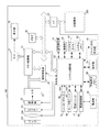
図2は、本実施形態に係るデジタルカメラ100の構成例を示すブロック図である。
図2において、撮影レンズ103はズームレンズ、フォーカスレンズを含むレンズ群である。シャッター101は絞り機能を備えるシャッターである。撮像部22は光学像を電気信号に変換するCCDやCMOS素子等で構成される撮像素子である。A/D変換器23は、撮像部22から出力されるアナログ信号をデジタル信号に変換するために用いられる。
FIG. 2 is a block diagram showing a configuration example of the
In FIG. 2, the photographing
画像処理部24は、A/D変換器23からのデータ、又は、メモリ制御部15からのデータに対し所定の画素補間、縮小といったリサイズ処理や色変換処理を行う。また、画像処理部24は、撮像した画像データを用いて所定の演算処理を行い、得られた演算結果に基づいてシステム制御部50が露光制御、測距制御を行う。これにより、TTL(スルー・ザ・レンズ)方式のAF処理(オートフォーカス処理)、AE処理(自動露出処理)、EF処理(フラッシュプリ発光処理)が行われる。画像処理部24では更に、撮像した画像データを用いて所定の演算処理を行い、得られた演算結果に基づいてTTL方式のAWB処理(オートホワイトバランス処理)も行う。
The
A/D変換器23からの出力データは、画像処理部24及びメモリ制御部15を介して、或いは、画像処理部24を介さずメモリ制御部15を介してメモリ32に直接書き込まれる。メモリ32は、撮像部22によって得られA/D変換器23によりデジタルデータに変換された画像データや、表示部28に表示するための画像データ(アイテム等)を格納する。メモリ32は、所定枚数の静止画像や所定時間の動画像及び音声を格納するのに十分な記憶容量を備えている。
また、メモリ32は画像表示用のメモリ(ビデオメモリ)を兼ねている。D/A変換器13は、メモリ32に格納されている画像表示用のデータをアナログ信号に変換して表示部28に供給する。こうして、メモリ32に書き込まれた表示用の画像データはD/A変換器13を介して表示部28により表示される。表示部28は、LCD等の表示器上に、D/A変換器13からのアナログ信号に応じた表示を行う。A/D変換器23によって一度A/D変換されメモリ32に蓄積されたデジタル信号をD/A変換器13においてアナログ変換し、表示部28に逐次転送して表示することで、電子ビューファインダとして機能し、スルー画像表示(ライブビュー表示)を行える。
The output data from the A /
Further, the
不揮発性メモリ56は、システム制御部50によって電気的に消去・記録・読出し可能な記録媒体としてのメモリであり、例えばEEPROM等が用いられる。不揮発性メモリ56には、システム制御部50の動作用の定数、プログラム等が記憶される。ここでいう、プログラムとは、本実施形態にて後述する各種フローチャートを実行するためのコンピュータプログラムのことである。
システム制御部50は、少なくとも1つのプロセッサーを内蔵し、デジタルカメラ100全体を制御する。前述した不揮発性メモリ56に記録されたプログラムを実行することで、後述する本実施形態の各処理を実現する。システムメモリ52には、RAMが用いられる。システムメモリ52には、システム制御部50の動作用の定数、変数、不揮発性メモリ56から読み出したプログラム等を展開する。また、システム制御部50はメモリ32、D/A変換器13、表示部28等を制御することにより表示制御も行う。
The
The
システムタイマー53は、各種制御に用いる時間や、内蔵された時計の時間を計測する計時部である。
通信部54は、無線又は有線ケーブルによって接続し、映像信号や音声信号の送受信を行う。通信部54は、無線LAN(Local Area Network)やインターネットとも接続可能である。通信部54は、撮像部22で撮像された画像(スルー画像を含む)や、記録媒体200に記録された画像を送信可能であり、また、外部機器から画像データやその他の各種情報を受信することができる。
姿勢検知部55は、重力方向に対するデジタルカメラ100の姿勢を検知する。姿勢検知部55で検知された姿勢に基づいて、撮像部22で撮影された画像が、デジタルカメラ100を横に構えて撮影された画像であるか、縦に構えて撮影された画像なのかを判別可能である。姿勢検知部55としては、加速度センサーやジャイロセンサー等を用いることができる。
The
The
The
モード切替スイッチ60、シャッターボタン61、操作部70はシステム制御部50に各種の動作指示を入力するための操作手段である。モード切替スイッチ60は、システム制御部50の動作モードを静止画記録モード、動画撮影モード、再生モード等のいずれかに切り替える。
第1シャッタースイッチ62は、デジタルカメラ100に設けられたシャッターボタン61の操作途中、いわゆる半押し(撮影準備指示)でONとなり第1シャッタースイッチ信号SW1を発生する。第1シャッタースイッチ信号SW1により、AF処理、AE処理、AWB処理、EF処理等の動作を開始する。
第2シャッタースイッチ64は、シャッターボタン61の操作完了、いわゆる全押し(撮影指示)でONとなり、第2シャッタースイッチ信号SW2を発生する。システム制御部50は、第2シャッタースイッチ信号SW2により、撮像部22による静止画撮像動作、撮像部22からの信号読み出しから記録媒体200に画像データを書き込むまでの一連の撮影処理の動作を開始する。
操作部70の各操作部材は、表示部28に表示される種々の機能アイコンを選択操作すること等により、場面ごとに適宜機能が割り当てられ、各種機能ボタンとして作用する。機能ボタンとしては、例えば終了ボタン、戻るボタン、画像送りボタン、ジャンプボタン、絞込みボタン、属性変更ボタン等がある。例えば、メニューボタンが押されると各種の設定可能なメニュー画面が表示部28に表示される。ユーザは、表示部28に表示されたメニュー画面と、上下左右の4方向ボタンやSETボタンとを用いて直感的に各種設定を行うことができる。
The
The
The
Each operation member of the
ファインダ内表示部41は、ファインダ16を介して視認可能な表示部であり、表示部28と同様にスルー画像や、アイテム等の表示をすることができる。
電源制御部80は、電池検出回路、DC−DCコンバータ、通電するブロックを切り替えるスイッチ回路等により構成され、電池の装着の有無、電池の種類、電池残量の検出を行う。また、電源制御部80は、その検出結果及びシステム制御部50の指示に基づいてDC−DCコンバータを制御し、必要な電圧を必要な期間、記録媒体200を含む各部に供給する。
電源部30は、アルカリ電池やリチウム電池等の一次電池やNiCd電池やNiMH電池、Li電池等の二次電池、ACアダプター等からなる。
記録媒体I/F18は、メモリカードやハードディスク等の記録媒体200とのインターフェースである。記録媒体200は、撮影時に画像を記録するためのメモリカード等の不揮発性の記録媒体であり、半導体メモリや光ディスク、磁気ディスク等から構成される。
The
The power
The
The recording medium I /
上述したデジタルカメラ100では、中央1点AFや顔AFを用いた撮影が可能である。中央1点AFとは、撮影画面内の中央位置1点に対してAFを行うことである。顔AFとは、顔検出機能によって検出された撮影画面内の顔に対してAFを行うことである。AFの方法は、コントラストAF、位相差AF等いずれの方法でもよい。
With the above-mentioned
顔検出機能について説明する。システム制御部50は、顔検出対象の画像データを画像処理部24に送る。システム制御部50の制御下で画像処理部24は、当該画像データに水平方向バンドパスフィルタを作用させる。また、システム制御部50の制御下で画像処理部24は、処理された画像データに垂直方向バンドパスフィルタを作用させる。これら水平及び垂直方向のバンドパスフィルタにより、画像データよりエッジ成分が検出される。その後、システム制御部50は、検出されたエッジ成分に関してパターンマッチングを行い、目及び鼻、口、耳の候補群を抽出する。そして、システム制御部50は、抽出された目の候補群の中から、予め設定された条件(例えば2つの目の距離、傾き等)を満たすものを、目の対と判断し、目の対があるもののみ目の候補群として絞り込む。システム制御部50は、絞り込まれた目の候補群とそれに対応する顔を形成する他のパーツ(鼻、口、耳)を対応付け、また、予め設定した非顔条件フィルタを通すことで、顔を検出する。その後、システム制御部50は、顔の検出結果に応じて上記顔情報を出力し、処理を終了する。このとき、顔の数等の特徴量をシステムメモリ52に記憶する。
The face detection function will be described. The
以上のようにライブビュー表示或いは再生表示される画像データを画像解析して、画像データの特徴量を抽出して被写体情報を検出することが可能である。本実施形態では、被写体情報として顔情報を例に挙げたが、被写体情報には他にも赤目判定や目の検出、目つむり検出、笑顔検出等の様々な情報がある。
なお、顔AFと同時に顔AE、顔FE、顔WBを行うことができる。顔AEとは、検出された顔の明るさに合わせて、画面全体の露出を最適化することである。顔FEとは、検出された顔を中心にフラッシュの調光をすることである。顔WBとは、検出された顔の色に合わせて画面全体のWBを最適化することである。
As described above, it is possible to perform image analysis on the image data displayed in the live view or reproduced, extract the feature amount of the image data, and detect the subject information. In the present embodiment, face information is taken as an example of subject information, but the subject information also includes various information such as red-eye determination, eye detection, eye blindness detection, and smile detection.
In addition, face AE, face FE, and face WB can be performed at the same time as face AF. Face AE is to optimize the exposure of the entire screen according to the detected brightness of the face. Face FE is to dimm the flash around the detected face. The face WB is to optimize the WB of the entire screen according to the detected face color.
図3は、本実施形態に係るデジタルカメラ100による処理動作を示すフローチャートである。この処理は、システム制御部50が、不揮発性メモリ56に記録されたプログラムをシステムメモリ52に展開して実行することで実現される。図3の処理動作に際して、撮像部22により撮像された画像を表示部28に逐次表示するライブビュー表示が実行されている。
ステップS301で、システム制御部50は、顔追尾AFに設定されているか、1点AFに設定されているかを判定する。顔追尾AFに設定されていると判定した場合、ステップS302に処理を進め、1点AFに設定されていると判定した場合、ステップS324に処理を進める。
FIG. 3 is a flowchart showing a processing operation by the
In step S301, the
ステップS301において顔追尾AFに設定されていると判定した場合、ステップS302で、システム制御部50は、顔領域でAFを実施するフラグ(顔領域AFフラグと呼ぶ)をOFFにする。顔領域AFフラグは、システムメモリ52に格納される。
ステップS303で、システム制御部50は、撮像部22で撮像された画像中に人物の顔が検出されているか否かを判定する。例えば撮像部22で撮像された画像において顔の大きさが所定の大きさ以上のときに、顔を検出可能であるとする。顔の検出は定期的に実施され、検出結果はシステムメモリ52に格納される。顔が検出されていると判定した場合、ステップS304に処理を進め、顔が検出されていないと判定した場合、ステップS305に処理を進める。
When it is determined in step S301 that the face tracking AF is set, the
In step S303, the
ステップS304で、システム制御部50は、システムメモリ52を参照し、図4(a)に示すように、表示部28に表示するスルー画像に重畳させて、顔領域を示す顔枠401を表示する。このようにシャッターボタン61の半押しによる撮影準備指示がされる前に顔を検出したことに応じて、表示部28に第1のアイテムとして顔枠401を表示する。顔枠401は、顔を囲うように、顔の大きさに基づいた大きさで表示される。なお、ステップS303において顔が検出されていない場合、顔枠401は表示されず、表示部28にはライブビュー画像のみが表示される。
In step S304, the
ステップS305で、システム制御部50は、第1シャッタースイッチ信号SW1がONであるか否か、すなわちシャッターボタン61の半押しによる撮影準備指示がされたか否かを判定する。撮影準備指示がされていないと判定した場合、ステップS303に処理を戻し、撮影準備指示がされたと判定した場合、ステップS306に処理を進める。
ステップS306で、システム制御部50は、ステップS303と同様、撮像部22で撮像された画像中に顔が検出されているか否かを判定する。顔が検出されていると判定した場合、ステップS307に処理を進め、顔が検出されていないと判定した場合、ステップS312に処理を進める。
In step S305, the
In step S306, the
ステップS307で、システム制御部50は、顔領域AFフラグをONにする。顔領域AFフラグは、システムメモリ52に格納される。顔領域AFフラグは、顔が検出された状態で撮影準備指示がされたことを示すフラグである。顔領域AFフラグがONである場合には、検出されていた顔領域においてAF処理を行うように制御する。
ステップS308で、システム制御部50は、顔領域、すなわち顔枠401が表示されている位置においてAF処理をし、顔領域への追尾を開始する。
ステップS309で、システム制御部50は、AF処理を実施した結果、顔領域で合焦したか否かを判定する。顔領域で合焦したと判定した場合、ステップS310に処理を進め、顔領域で合焦していないと判定した場合、ステップS311に処理を進める。
In step S307, the
In step S308, the
In step S309, the
ステップS310で、システム制御部50は、図4(b)に示すように、表示部28に表示するスルー画像に重畳させて、合焦用顔枠402を表示する。合焦用顔枠402は、顔枠401の表示形態を変えたものであり、顔を囲う一の枠として表示される。その後、システム制御部50は、ステップS319に処理を進める。
ステップS311で、システム制御部50は、図4(c)に示すように、表示部28に表示するスルー画像に重畳させて、非合焦用顔枠403を表示する。非合焦用顔枠403は、顔枠401の表示形態を変えたものである。その後、システム制御部50は、ステップS319に処理を進める。
In step S310, the
In step S311 the
ステップS312で、システム制御部50は、顔領域AFフラグをOFFにする。
ステップS313で、システム制御部50は、AF処理し、合焦した被写体への追尾を開始する。AF処理を実施する領域は画面全体でも良いし、画面の中央付近等の限定した領域でも良い。なお、限定した領域は画面の中央付近に限らない。また、限定した領域は、予め定められていても良いし、撮影準備指示の実施前にユーザが指定できるようにしても良い。この所定領域を所定数で分割した領域でAF処理を行い、各分割した領域で合焦したか否かを判定する。本実施形態では、画面の8割を所定領域とし、横7分割、縦7分割した各領域でAF処理を実施するものとする。
ステップS314で、システム制御部50は、ステップS313においてAF処理を実施した結果、合焦領域があるか否かを判定する。合焦領域があると判定した場合、ステップS315に処理を進め、合焦領域がないと判定した場合、ステップS318に処理を進める。
In step S312, the
In step S313, the
In step S314, the
ステップS315で、システム制御部50は、図5(a)に示すように、表示部28に表示するスルー画像に重畳させて、合焦枠501を表示する。合焦枠501は、合焦領域を示す枠として表示される。図5(a)に示す状態は、人物が写っているが、顔の大きさが所定の大きさ以上でないため、顔検出がなされていない。このように顔を検出していない状態でシャッターボタン61の半押しによる撮影準備指示がされたことに応じて、表示部28に第2のアイテムとして合焦枠501を表示する。さらにスルー画像内の人物の大きさが大きくなると合焦領域が大きくなり、図5(c)に示すように、図5(a)に比べて合焦枠501が広い範囲に表示される。よって、撮影準備指示がされる前に顔を検出した場合よりも顔の中で枠が重畳して表示されている領域が大きくなる。すなわち、合焦枠501(後述する顔用合焦枠503)が表示される場合には、顔枠401や合焦用顔枠402が表示される場合よりも顔に重畳して表示される領域が大きくなり、顔の視認性が低下しやすい。
ステップS316で、システム制御部50は、合焦枠501内において顔が検出されているか否かを判定する。顔が検出されていると判定した場合、ステップS317に処理を進め、顔が検出されていないと判定した場合、ステップS319に処理を進める。
In step S315, the
In step S316, the
ステップS317で、システム制御部50は、図5(d)に示すように、表示部28に表示するスルー画像に重畳させて、顔用合焦枠503を表示する。図5(d)は、顔の大きさが所定の大きさ以上となり、顔検出がされて、顔のある領域の表示が合焦枠501から顔用合焦枠503となった場合の表示例を示している。顔用合焦枠503は、合焦領域において人物の顔が検出されたことを示している。顔用合焦枠503は、合焦領域内において検出された人物の顔の位置を示す表示であり、人物の顔の視認性が低下しないようにしている。なお、顔の検出されなかった領域の合焦枠501の表示形態は変わらない。顔用合焦枠503は、合焦枠501の表示形態を変えて、顔の表情を見やすくするようにしたものである。この場合に、例えば図5(d)に示すように、顔用合焦枠503は、顔の大きさに応じて、その表示形態を可変とする。その後、システム制御部50は、ステップS319に処理を進める。
In step S317, as shown in FIG. 5D, the
図5(d)は顔用合焦枠の一例を示しており、合焦枠501の表示形態を実線から点線にした顔用合焦枠503を示している。顔用合焦枠の表示例は、図5(e)、(f)に示すものでもよい。図5(e)では、顔用合焦枠503の透過度を合焦枠のときよりも高くした表示例を示している。図5(f)では、顔用合焦枠503を四角形から角のみを示した表示にしている。その他にも、数を少なくしたり、枠の大きさを大きくしたりしてもよい。顔用合焦枠は合焦枠と比べて、顔に重畳して表示される部分(枠と重なって見えない顔の領域)が小さくなる、又は透過度が高くなることにより顔の部分の視認性を上げる表示である。また、合焦枠は合焦範囲を示すために顔に重畳して複数表示されるが、顔用合焦枠は検出された顔の大きさに合わせて表示をするので、合焦枠が複数合わさった大きさの枠となる。言い換えれば、顔用合焦枠は検出された顔の大きさに基づいた大きさで(顔の視認性が低下しないように)表示されるが、合焦枠は顔を検出していたとしても顔の大きさに基づかず表示されているので、顔に重なり視認性が低下してしまう。しかし、顔に重なって表示されていたとしても上述したように表示形態を変えることで視認性の低下を低減することができる。なお、図5(g)に示すように、顔用合焦枠503が顔に対して十分に小さいものとなれば、顔用合焦枠503の透過率を上げたり、線の数を少なくしたりするのを止めて、顔の表情を見やすくするよりも、合焦領域を示すようにしても良い。なお、顔用合焦枠の表示形態は、上述したものの他に、形状、サイズ、色等を変えてもよい。
ステップS318で、システム制御部50は、図5(b)に示すように、表示部28に表示するスルー画像に重畳させて、非合焦表示502を表示する。その後、システム制御部50は、ステップS319に処理を進める。
FIG. 5D shows an example of the focusing frame for the face, and shows the focusing
In step S318, the
ステップS319で、システム制御部50は、撮影準備指示が継続され、連続したAF処理が継続されているか否かを判定する。撮影準備指示が継続されていると判定した場合、ステップS320に処理を進め、撮影準備指示が継続されていないと判定した場合、ステップS321に処理を進める。
ステップS320で、システム制御部50は、顔領域AFフラグがONであるか否かを判定する。顔領域AFフラグがONであると判定した場合、ステップS308に処理を戻し、システムメモリ52に格納されている顔検出情報に基づき、顔領域においてAF処理を繰り返す。この処理を繰り返すことにより、顔を検出し続け、顔にピントを合わせ続けることができる。顔領域フラグがOFFであると判定した場合、ステップS313に処理を戻し、画面の所定領域にてAF処理を繰り返す。
ステップS321で、システム制御部50は、第2シャッタースイッチ信号SW2がONであるか否か、すなわちシャッターボタン61の全押しによる撮影指示がされたか否かを判定する。撮影指示がされていると判定した場合、ステップS322に処理を進め、撮影指示がされていないと判定した場合、ステップS323に処理を進める。
ステップS322で、システム制御部50は、撮影処理を実行して、処理を完了する。
ステップS323で、システム制御部50は、シャッターボタン61の押下が停止されて撮影準備指示が解除されたので、表示部28に表示するスルー画像に重畳させて表示していたアイテムを消して、処理を完了する。
In step S319, the
In step S320, the
In step S321, the
In step S322, the
In step S323, since the pressing of the
一方、ステップS301において1点AFに設定されていると判定した場合、ステップS324で、システム制御部50は、表示部28の画面の中央にAF枠を表示する。
ステップS325で、システム制御部50は、ユーザによりAF枠の移動操作がなされたか否かを判定する。AF枠の移動操作がなされたと判定した場合、ステップS326に処理を進め、AF枠の移動操作がなされていないと判定した場合、ステップS327に処理を進める。
ステップS326で、システム制御部50は、AF枠の移動操作に従ってAF枠を表示する位置を変更する。
On the other hand, if it is determined in step S301 that the one-point AF is set, in step S324, the
In step S325, the
In step S326, the
ステップS327で、システム制御部50は、シャッターボタン61の半押しによる撮影準備指示がされたか否かを判定する。撮影準備指示がされていないと判定した場合、ステップS325に処理を戻し、撮影準備指示がされたと判定した場合、ステップS328に処理を進める。
ステップS328で、システム制御部50は、AF枠が表示されている位置においてAF処理を実施し、合焦枠を表示する。1点AF時は、撮影準備指示がされた後にはAF枠は移動せず、合焦枠は例えばAF枠の線を太く表示したものとすれば良い。
In step S327, the
In step S328, the
ステップS329で、システム制御部50は、シャッターボタン61の全押しによる撮影指示がされたか否かを判定する。撮影指示がされていると判定した場合、ステップS330に処理を進め、撮影指示がされていないと判定した場合、ステップS331に処理を進める。
ステップS330で、システム制御部50は、撮影処理を実行して、処理を完了する。
ステップS331で、システム制御部50は、撮影準備指示が継続されているか否かを判定する。撮影準備指示が継続されていると判定した場合、ステップS329に処理を戻し、撮影準備指示が継続されていないと判定した場合、ステップS324に処理を戻す。
In step S329, the
In step S330, the
In step S331, the
以上述べたように、追尾対象とする人物の顔が未検出の状態で合焦しているときに、顔が検出された場合、合焦領域に顔があると、合焦枠501の表示形態を変えた顔用合焦枠503を表示するようにして、顔の表情を見やすくすることができる。このように撮像された画像と共にアイテムを表示部28に表示するときに、所定の被写体の状態を視認しやすくすることができる。
顔を検出する前に、AF処理を行い、追尾を開始すると合焦枠が表示され、スルー画像における顔の大きさが大きくなっても、顔に重なるように合焦枠501が表示されてしまう。しかし、顔が検出されたことに応じて顔の領域の合焦枠の表示形態を変え、顔の視認性が向上するようにするので、ユーザは顔の表情を確認しつつ、顔に合焦していることを認識することができる。一方で、AF処理を行う前に顔が検出されていた場合には、顔を囲うように顔枠401が表示されている。よって、スルー画像内における顔の大きさが変わったり、位置が変わったりしても、検出済みの顔の大きさに合わせて顔枠を表示するので、途中で顔の視認性が低下しない。
なお、上述の実施形態では表示部28において合焦枠等の表示を行うことを説明したがユーザがファインダを覗いており、ファインダ内表示部41に表示をしているときにはファインダ内表示部41において表示を行うようにしてもよい。
As described above, if a face is detected when the face of the person to be tracked is in focus in an undetected state, and if there is a face in the focusing area, the display form of the focusing
If AF processing is performed before the face is detected and tracking is started, the focusing frame is displayed, and even if the size of the face in the through image becomes large, the focusing
In the above-described embodiment, it has been described that the in-focus frame and the like are displayed on the
以上、本発明を実施形態と共に説明したが、上記実施形態は本発明を実施するにあたっての具体化の例を示したものに過ぎず、これらによって本発明の技術的範囲が限定的に解釈されてはならないものである。すなわち、本発明はその技術思想、又はその主要な特徴から逸脱することなく、様々な形で実施することができる。
本実施形態では、所定の被写体として人物の顔を例としたが、それに限られるものではない。例えば色や形に特徴があり、その状態を確認したいとの要求がありえるので、色や形といった特徴量に基づいて検出される被写体を対象としても良い。
また、システム制御部50が行うものとして説明した各種処理は、1つのハードウェアが行っても良いし、複数のハードウェア(例えば複数のプロセッサや回路)が処理を分担すること行っても良い。
Although the present invention has been described above together with the embodiments, the above-described embodiments merely show examples of embodiment of the present invention, and the technical scope of the present invention is interpreted in a limited manner by these. It should not be. That is, the present invention can be implemented in various forms without departing from the technical idea or its main features.
In the present embodiment, a person's face is taken as an example as a predetermined subject, but the present invention is not limited thereto. For example, since there is a feature in color and shape and there may be a request to confirm the state, a subject detected based on a feature amount such as color and shape may be targeted.
Further, the various processes described as those performed by the
また、実施形態においては、本発明をデジタルカメラに適用した例を説明したが、本発明は、ライブビュー画像上に、検出された所定の被写体を示すアイテムの表示を制御可能な撮像制御装置であれば適用可能である。すなわち、本発明は、カメラ以外にも、カメラ機能付きの各種端末(携帯電話端末、タブレット端末、スマートフォン等)にも適用可能である。
(その他の実施形態)
本発明は、上述の実施形態の1以上の機能を実現するプログラムを、ネットワーク又は記憶媒体を介してシステム又は装置に供給し、そのシステム又は装置のコンピュータにおける1つ以上のプロセッサーがプログラムを読出し実行する処理でも実現可能である。また、1以上の機能を実現する回路(例えば、ASIC)によっても実現可能である。
Further, in the embodiment, an example in which the present invention is applied to a digital camera has been described, but the present invention is an imaging control device capable of controlling the display of an item indicating a detected predetermined subject on a live view image. If there is, it is applicable. That is, the present invention can be applied not only to a camera but also to various terminals having a camera function (mobile phone terminal, tablet terminal, smartphone, etc.).
(Other embodiments)
The present invention supplies a program that realizes one or more functions of the above-described embodiment to a system or device via a network or storage medium, and one or more processors in the computer of the system or device reads and executes the program. It can also be realized by the processing to be performed. It can also be realized by a circuit (for example, ASIC) that realizes one or more functions.
22:撮像部、24:画像処理部、28:表示部、50:システム制御部、52:システムメモリ、56:不揮発性メモリ、100:デジタルカメラ 22: Imaging unit, 24: Image processing unit, 28: Display unit, 50: System control unit, 52: System memory, 56: Non-volatile memory, 100: Digital camera
Claims (17)
前記撮像部により撮像されたライブビュー画像を表示部に表示する表示制御手段と、
撮影準備指示がされる前に前記検出手段が前記所定の被写体を検出したことに応じて、前記ライブビュー画像に重畳して第1のアイテムを表示し、
前記検出手段が前記所定の被写体を検出していない状態で撮影準備指示がされ、合焦したことに応じて、前記ライブビュー画像に重畳して第2のアイテムを表示し、
前記第2のアイテムを表示した後に前記検出手段が前記所定の被写体を検出したことに応じて、前記第2のアイテムの表示形態を変えるように制御する制御手段とを有することを特徴とする撮像制御装置。 A detection means for detecting a predetermined subject in an image captured by an imaging unit, and
A display control means for displaying a live view image captured by the imaging unit on the display unit, and
In response to the detection means detecting the predetermined subject before the shooting preparation instruction is given, the first item is displayed by superimposing it on the live view image.
A shooting preparation instruction is given in a state where the detection means has not detected the predetermined subject, and in response to the focus , the second item is displayed by superimposing the live view image.
Imaging characterized by having a control means for controlling the display form of the second item to be changed in response to the detection means detecting the predetermined subject after displaying the second item. Control device.
前記撮像部により撮像されたライブビュー画像を表示部に表示するステップと、
撮影準備指示がされる前に前記所定の被写体を検出したことに応じて、前記ライブビュー画像に重畳して第1のアイテムを表示し、
前記所定の被写体を検出していない状態で撮影準備指示がされ、合焦したことに応じて、前記ライブビュー画像に重畳して第2のアイテムを表示し、
前記第2のアイテムを表示した後に前記所定の被写体を検出したことに応じて、前記第2のアイテムの表示形態を変えるように制御するステップとを有することを特徴とする撮像装置の制御方法。 It is a control method of an image pickup apparatus having a function of detecting a predetermined subject in an image captured by an image pickup unit.
A step of displaying the live view image captured by the imaging unit on the display unit, and
In response to the detection of the predetermined subject before the shooting preparation instruction is given, the first item is displayed by superimposing it on the live view image.
When the shooting preparation instruction is given in a state where the predetermined subject is not detected and the subject is in focus , the second item is displayed by superimposing it on the live view image.
A control method for an imaging device, which comprises a step of controlling the display form of the second item to be changed according to the detection of the predetermined subject after displaying the second item.
Priority Applications (1)
| Application Number | Priority Date | Filing Date | Title |
|---|---|---|---|
| JP2016205347A JP6768449B2 (en) | 2016-10-19 | 2016-10-19 | Imaging control device, control method and program of imaging device |
Applications Claiming Priority (1)
| Application Number | Priority Date | Filing Date | Title |
|---|---|---|---|
| JP2016205347A JP6768449B2 (en) | 2016-10-19 | 2016-10-19 | Imaging control device, control method and program of imaging device |
Publications (2)
| Publication Number | Publication Date |
|---|---|
| JP2018067802A JP2018067802A (en) | 2018-04-26 |
| JP6768449B2 true JP6768449B2 (en) | 2020-10-14 |
Family
ID=62086406
Family Applications (1)
| Application Number | Title | Priority Date | Filing Date |
|---|---|---|---|
| JP2016205347A Active JP6768449B2 (en) | 2016-10-19 | 2016-10-19 | Imaging control device, control method and program of imaging device |
Country Status (1)
| Country | Link |
|---|---|
| JP (1) | JP6768449B2 (en) |
Families Citing this family (2)
| Publication number | Priority date | Publication date | Assignee | Title |
|---|---|---|---|---|
| JP7293025B2 (en) | 2019-07-29 | 2023-06-19 | キヤノン株式会社 | Imaging device and its control method |
| JP6882417B2 (en) * | 2019-10-10 | 2021-06-02 | キヤノン株式会社 | Display control device |
Family Cites Families (6)
| Publication number | Priority date | Publication date | Assignee | Title |
|---|---|---|---|---|
| JP2003107335A (en) * | 2001-09-28 | 2003-04-09 | Ricoh Co Ltd | Image pickup device, automatic focusing method, and program for making computer execute the method |
| JP4182117B2 (en) * | 2006-05-10 | 2008-11-19 | キヤノン株式会社 | IMAGING DEVICE, ITS CONTROL METHOD, PROGRAM, AND STORAGE MEDIUM |
| JP5233720B2 (en) * | 2009-02-12 | 2013-07-10 | ソニー株式会社 | IMAGING DEVICE, IMAGING DEVICE CONTROL METHOD, AND PROGRAM |
| JP2014017665A (en) * | 2012-07-09 | 2014-01-30 | Canon Inc | Display control unit, control method for display control unit, program, and recording medium |
| JP6418827B2 (en) * | 2014-07-16 | 2018-11-07 | キヤノン株式会社 | Imaging apparatus and control method thereof |
| JP5911557B2 (en) * | 2014-12-16 | 2016-04-27 | オリンパス株式会社 | Imaging device |
-
2016
- 2016-10-19 JP JP2016205347A patent/JP6768449B2/en active Active
Also Published As
| Publication number | Publication date |
|---|---|
| JP2018067802A (en) | 2018-04-26 |
Similar Documents
| Publication | Publication Date | Title |
|---|---|---|
| CN110636211B (en) | Electronic device, lens unit, control method thereof, and computer-readable medium | |
| CN108377329B (en) | Image pickup apparatus and control method thereof | |
| US9036073B2 (en) | Imaging apparatus and for controlling an automatic focus (AF) area and an enlargement area in a live view | |
| US9819857B2 (en) | Electronic apparatus, control method for the same, and image capturing apparatus | |
| CN107040718B (en) | Display control apparatus and control method thereof | |
| JP6512961B2 (en) | Imaging control apparatus, control method therefor, program, and storage medium | |
| JP2014228629A (en) | Imaging apparatus, control method and program thereof, and storage medium | |
| JP6460868B2 (en) | Display control apparatus and control method thereof | |
| US10388035B2 (en) | Image processing apparatus, image processing method, and storage medium | |
| JP7293025B2 (en) | Imaging device and its control method | |
| JP2014017665A (en) | Display control unit, control method for display control unit, program, and recording medium | |
| US10511761B2 (en) | Image capturing control apparatus, control method, and storage medium | |
| JP2009060291A (en) | Image processing apparatus, image processing method and program | |
| US20190149730A1 (en) | Image capturing control apparatus and control method therefor | |
| JP6768449B2 (en) | Imaging control device, control method and program of imaging device | |
| JP2019219584A (en) | Electronic device and control method therefor | |
| JP6324278B2 (en) | Imaging apparatus, image processing apparatus, and control method thereof | |
| CN107800956B (en) | Image pickup apparatus, control method, and storage medium | |
| JP6758843B2 (en) | Shooting control device and its control method | |
| JP2015034895A (en) | Imaging device and control method for the same | |
| JP7532042B2 (en) | IMAGING CONTROL DEVICE, CONTROL METHOD FOR IMAGING CONTROL DEVICE, PROG | |
| EP3879813B1 (en) | Electronic apparatus and control method thereof | |
| JP7077022B2 (en) | Electronic devices and their control methods | |
| JP6851788B2 (en) | Focus control device, control method and program of focus control device | |
| JP6971709B2 (en) | Imaging device and its control method |
Legal Events
| Date | Code | Title | Description |
|---|---|---|---|
| A621 | Written request for application examination |
Free format text: JAPANESE INTERMEDIATE CODE: A621 Effective date: 20190709 |
|
| A977 | Report on retrieval |
Free format text: JAPANESE INTERMEDIATE CODE: A971007 Effective date: 20200227 |
|
| A131 | Notification of reasons for refusal |
Free format text: JAPANESE INTERMEDIATE CODE: A131 Effective date: 20200310 |
|
| A521 | Request for written amendment filed |
Free format text: JAPANESE INTERMEDIATE CODE: A523 Effective date: 20200401 |
|
| TRDD | Decision of grant or rejection written | ||
| A01 | Written decision to grant a patent or to grant a registration (utility model) |
Free format text: JAPANESE INTERMEDIATE CODE: A01 Effective date: 20200825 |
|
| A61 | First payment of annual fees (during grant procedure) |
Free format text: JAPANESE INTERMEDIATE CODE: A61 Effective date: 20200923 |
|
| R151 | Written notification of patent or utility model registration |
Ref document number: 6768449 Country of ref document: JP Free format text: JAPANESE INTERMEDIATE CODE: R151 |