CN107040718B - Display control apparatus and control method thereof - Google Patents
Display control apparatus and control method thereof Download PDFInfo
- Publication number
- CN107040718B CN107040718B CN201710062543.XA CN201710062543A CN107040718B CN 107040718 B CN107040718 B CN 107040718B CN 201710062543 A CN201710062543 A CN 201710062543A CN 107040718 B CN107040718 B CN 107040718B
- Authority
- CN
- China
- Prior art keywords
- focus
- display
- index
- unit
- control
- Prior art date
- Legal status (The legal status is an assumption and is not a legal conclusion. Google has not performed a legal analysis and makes no representation as to the accuracy of the status listed.)
- Active
Links
Images


Classifications
-
- H—ELECTRICITY
- H04—ELECTRIC COMMUNICATION TECHNIQUE
- H04N—PICTORIAL COMMUNICATION, e.g. TELEVISION
- H04N23/00—Cameras or camera modules comprising electronic image sensors; Control thereof
- H04N23/60—Control of cameras or camera modules
- H04N23/63—Control of cameras or camera modules by using electronic viewfinders
- H04N23/633—Control of cameras or camera modules by using electronic viewfinders for displaying additional information relating to control or operation of the camera
- H04N23/635—Region indicators; Field of view indicators
-
- H—ELECTRICITY
- H04—ELECTRIC COMMUNICATION TECHNIQUE
- H04N—PICTORIAL COMMUNICATION, e.g. TELEVISION
- H04N23/00—Cameras or camera modules comprising electronic image sensors; Control thereof
- H04N23/10—Cameras or camera modules comprising electronic image sensors; Control thereof for generating image signals from different wavelengths
-
- H—ELECTRICITY
- H04—ELECTRIC COMMUNICATION TECHNIQUE
- H04N—PICTORIAL COMMUNICATION, e.g. TELEVISION
- H04N23/00—Cameras or camera modules comprising electronic image sensors; Control thereof
- H04N23/60—Control of cameras or camera modules
- H04N23/61—Control of cameras or camera modules based on recognised objects
- H04N23/611—Control of cameras or camera modules based on recognised objects where the recognised objects include parts of the human body
-
- H—ELECTRICITY
- H04—ELECTRIC COMMUNICATION TECHNIQUE
- H04N—PICTORIAL COMMUNICATION, e.g. TELEVISION
- H04N23/00—Cameras or camera modules comprising electronic image sensors; Control thereof
- H04N23/60—Control of cameras or camera modules
- H04N23/62—Control of parameters via user interfaces
-
- H—ELECTRICITY
- H04—ELECTRIC COMMUNICATION TECHNIQUE
- H04N—PICTORIAL COMMUNICATION, e.g. TELEVISION
- H04N23/00—Cameras or camera modules comprising electronic image sensors; Control thereof
- H04N23/60—Control of cameras or camera modules
- H04N23/63—Control of cameras or camera modules by using electronic viewfinders
- H04N23/631—Graphical user interfaces [GUI] specially adapted for controlling image capture or setting capture parameters
-
- H—ELECTRICITY
- H04—ELECTRIC COMMUNICATION TECHNIQUE
- H04N—PICTORIAL COMMUNICATION, e.g. TELEVISION
- H04N23/00—Cameras or camera modules comprising electronic image sensors; Control thereof
- H04N23/60—Control of cameras or camera modules
- H04N23/67—Focus control based on electronic image sensor signals
- H04N23/672—Focus control based on electronic image sensor signals based on the phase difference signals
-
- H—ELECTRICITY
- H04—ELECTRIC COMMUNICATION TECHNIQUE
- H04N—PICTORIAL COMMUNICATION, e.g. TELEVISION
- H04N25/00—Circuitry of solid-state image sensors [SSIS]; Control thereof
- H04N25/10—Circuitry of solid-state image sensors [SSIS]; Control thereof for transforming different wavelengths into image signals
- H04N25/11—Arrangement of colour filter arrays [CFA]; Filter mosaics
- H04N25/13—Arrangement of colour filter arrays [CFA]; Filter mosaics characterised by the spectral characteristics of the filter elements
- H04N25/134—Arrangement of colour filter arrays [CFA]; Filter mosaics characterised by the spectral characteristics of the filter elements based on three different wavelength filter elements
-
- H—ELECTRICITY
- H04—ELECTRIC COMMUNICATION TECHNIQUE
- H04N—PICTORIAL COMMUNICATION, e.g. TELEVISION
- H04N25/00—Circuitry of solid-state image sensors [SSIS]; Control thereof
- H04N25/70—SSIS architectures; Circuits associated therewith
- H04N25/703—SSIS architectures incorporating pixels for producing signals other than image signals
- H04N25/704—Pixels specially adapted for focusing, e.g. phase difference pixel sets
Landscapes
- Engineering & Computer Science (AREA)
- Multimedia (AREA)
- Signal Processing (AREA)
- Human Computer Interaction (AREA)
- Physics & Mathematics (AREA)
- Spectroscopy & Molecular Physics (AREA)
- Studio Devices (AREA)
- Focusing (AREA)
- Automatic Focus Adjustment (AREA)
- Adjustment Of Camera Lenses (AREA)
- Camera Bodies And Camera Details Or Accessories (AREA)
- Indication In Cameras, And Counting Of Exposures (AREA)
Abstract
The invention relates to a display control apparatus and a control method thereof. The display control means acquires focus state information indicating a focus state of a specific region having a different aspect ratio in a captured image; controlling to display a first display element representing the specific area and a second display element representing an in-focus state together with the captured image on a display unit; detecting a posture of the display control apparatus; and controlling to rotate and display the second display element without rotating the first display element in a case where the posture of the display control apparatus is changed from the first posture by 90 degrees to the second posture.
Description
Technical Field
The present invention relates to a display control apparatus and a control method thereof, and more particularly, to a focus guidance display control technique for enabling a user to perform focus adjustment.
Background
A display control apparatus (such as a digital camera) for taking moving images and still images has a focus guide function that allows a user to easily perform a focusing operation when the user manually performs focus adjustment. Examples of the focus guide function include a function of displaying a rotational direction of a focus ring serving as a focus operation unit for enabling a user to focus on a desired subject as a focus index (see japanese patent laid-open No. 5-308552), and a function of displaying a change in a focus angle with respect to the subject as a focus index (see japanese patent laid-open No. 2005-140943). Another example includes setting an arbitrary focus detection area, displaying a focusing frame, and acquiring distance information on a distance from an object included in the set focus detection area.
In recent years, there has also appeared a function of displaying a combination of the above-described focus index and focus frame as a focus guide, which enables a user to manually perform focus adjustment in a more accurate and intuitive manner.
The above-described focus guide can be a convenient indication for the user if configured as follows, for example, the focus guide is rotated by 90 degrees according to the posture of the camera when the posture of the camera is changed to the upright posture. However, if the focus frame (focus detection area) of the focus guide is rotated according to the change of the posture, the following problem may occur.
Specifically, the focus frame is not changed despite the fact that the camera posture is changed, and therefore if the range of the focus detection area is changed by changing the orientation of the focus frame, an image focused on a desired subject may not be captured. On the contrary, if only the focusing frame is rotated without changing the focus detection area, the focusing frame indicates an area different from the area where the focus detection is actually performed, which means that correct display cannot be achieved. In other words, this means that the direction of the focus detection area and the direction of the focus frame do not coincide with each other in a configuration in which the focus detection areas have different aspect ratios due to limitations in pixel configuration and the like in the image sensor.
Disclosure of Invention
The present invention has been made in consideration of the foregoing problems, and realizes a display control technique with which a focused state can be correctly displayed even when the posture of the apparatus is changed, and a guidance display that enables the user to easily perform focus adjustment is provided.
In order to solve the foregoing problems, the present invention provides a display control apparatus including: an acquisition unit configured to acquire focus state information indicating a focus state of a specific region having a different aspect ratio in a captured image obtained by the image capturing unit; a display control unit configured to control to display, on a display unit, a first display element indicating a specific area and a second display element indicating an in-focus state acquired by the acquisition unit together with a captured image; a posture detection unit configured to detect a posture of the display control apparatus; and a control unit configured to control to rotate and display the second display element without rotating the first display element, in a case where the posture detection unit detects that the posture of the display control apparatus is changed from the first posture to a second posture that is different by 90 degrees from the first posture.
In order to solve the foregoing problems, the present invention provides a control method of a display control apparatus, the control method including: acquiring focusing state information representing a focusing state of a specific region having a different aspect ratio in a captured image obtained by an image capturing unit; controlling to display, on the display unit, a first display element indicating a specific area and a second display element indicating an acquired in-focus state together with the captured image; and controlling to rotate and display the second display element without rotating the first display element in response to the posture detection unit detecting that the posture of the display control apparatus is changed from the first posture to the second posture which is different by 90 degrees from the first posture.
According to the present invention, it is possible to correctly display a focused state even when the posture of the apparatus is changed, and provide a guidance display that enables the user to easily perform focus adjustment.
Further features of the invention will become apparent from the following description of exemplary embodiments (with reference to the attached drawings).
Drawings
Fig. 1 is a block diagram of the configuration of a digital camera 10.
Fig. 2A and 2B are diagrams illustrating a light receiving surface of the image pickup element 102.
Fig. 3A-1 to 3B-2 show a flowchart illustrating a shooting mode process.
Fig. 4 is a flowchart illustrating the focus guide display process.
Fig. 5A and 5B are flowcharts illustrating focus guide display form determination processing.
Fig. 6 is a flowchart illustrating a process of determining whether the rotation of the focus index is valid or invalid.
Fig. 7A to 7C show display examples of the focus guide.
Fig. 8A to 8I show display examples of the focus guide screen when the face detection function is off.
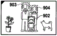
Fig. 9A to 9I show display examples of the focus guide screen when the face detection function is on.
Detailed Description
Hardware structure
Fig. 1 illustrates an example of a hardware configuration of a digital camera 10 as an example of a display control apparatus according to the present invention.
The housing 100 is an outer jacket enclosing many constituent elements of the digital camera 10 and various types of operation units, the display unit 107, and the external output unit 121 are exposed to the surface of the housing 100.
The interchangeable lens 101 is an imaging lens composed of a plurality of lens groups and has a focus lens, a zoom lens, a shift lens, and an aperture stop arranged therein.
The image pickup element 102 has a configuration in which a plurality of pixels each including a photoelectric conversion element are two-dimensionally arranged. In the image pickup element 102, an optical image of an object formed by the interchangeable lens 101 is photoelectrically converted by pixels, and further subjected to analog/digital conversion by an a/D conversion circuit to output an image signal (RAW image data) in units of pixels. A detailed description of the image pickup element 102 and the associated focus detection unit 108 used in the present embodiment will be given later with reference to fig. 2A and 2B.
The ND filter 103 is provided in the digital camera 10 so as to adjust the amount of incident light separately from an aperture stop provided in a lens.
The image processing unit 118 corrects a level difference caused by the image pickup element 102. For example, the image processing unit 118 corrects the level of pixels in the effective area by using pixels in an OB (optical black) area, and corrects defective pixels by using pixels around the defective pixels. The image processing unit 118 also performs various operation processes such as light attenuation correction at the frame edge, color correction, edge enhancement, noise removal, gamma correction, debayering (debayering), and compression. After the above-described processing is performed on the RAW image data input from the image pickup device 102, the image processing unit 118 outputs the corrected image data to the control unit.
Further, the image processing unit 118 detects an edge component from the image data by applying horizontal and vertical band pass filters to the image data. The main microcontroller 119 performs pattern matching with respect to the detected edge component to detect a subject such as a human face. In the case of face detection, candidate groups for eyes, nose, mouth, and ears are extracted, and a candidate group satisfying a preset condition (e.g., distance between eyes, inclination angle of eyes, color of eyes, etc.) is selected as a strong candidate group from among the extracted candidate groups. Then, the main microcontroller 119 associates the selected candidate group with corresponding other information (for example, in the case where the candidate group is an eye, other parts of the face than the eye, such as a nose, a mouth, and an ear), and performs filtering by using a preset conditional filter to extract the face. The user can specify an AF frame (main face frame) to any one face within the real-time display image displayed on the display unit 107.
The recording medium I/F unit 104 is an interface between the recording medium 105 and the digital camera 10, and is configured to control recording of image data input from the image processing unit 118 to the recording medium 105 and reading of the recorded image data.
The recording medium 105 is a recording medium including a semiconductor memory or the like for recording a captured video or image data, and is configured to record the image data and read the recorded image data in response to control of the recording medium I/F unit 104. The recording medium 105 is a removable memory card or the like, and may be a recording medium built in a camera.
The GPU 115 is a rendering engine (rendering engine) that renders various types of information displays and menu screens of the digital camera 10 in the VRAM. The GPU 115 has a zoom-in/zoom-out rendering function, a rotation rendering function, and a lamination success function in addition to a rendering function of rendering a character string and graphics. The VRAM for rendering includes an alpha channel representing transparency, and can display rendered contents on a camera image or a reproduction image in a screen display manner (on-screen display manner) through the display I/F unit 106.
The display I/F unit 106 performs superimposition/composition processing and resize (resize) processing on video data (captured image or reproduced image) from the image processing unit 118 and display content rendered into the VRAM by the GPU 115, and then outputs (displays on the display unit 107) the result to the display unit 107. In the case where the enlargement display mode is set, the display I/F unit 106 performs superimposition/composition processing and resizing processing on a partial area of the video data. As a result, in the enlarged display mode, an enlarged video larger than that in the normal mode is displayed on the display unit 107, which enables the user to perform a focus adjustment operation (focusing operation) with higher accuracy during manual focusing.
The display unit 107 may be an external monitor that displays image data output from the display I/F unit 106 to enable a user to check the angle of view and can be viewed from the housing 100 side, or may be a display unit provided inside a viewfinder. The display unit 107 may be a liquid crystal display or an organic EL display (organic light emitting diode display) or the like.
The main controller 119 is a control unit that controls the overall operation of the digital camera 10, and may be a microcomputer or the like. The main microcontroller 119 includes a CPU119a, ROM 119b and RAM119 c. The CPU119a performs various types of operations in a flowchart to be described later by extracting a program stored in the ROM 119b to the RAM119c and executing the program.
A gain control unit 109, a shutter control unit 110, an ND control unit 111, and an aperture stop control unit 112, which will be described below, are functional blocks for exposure control. The main microcontroller 119 controls the respective image data output from the image processing unit 118 based on the calculation results of the luminance levels of these units (these calculations are performed by the main microcontroller 119) or based on the operation parameters manually set by the user.
The gain control unit 109 controls the gain of the image pickup element 102. The shutter control unit 110 controls the shutter speed of the image pickup element 102. The ND control unit 111 controls the amount of light incident on the image pickup element 102 via the ND filter 103. The aperture stop control unit 112 controls the aperture stop of the interchangeable lens 101.
The focus control unit 113 performs different operations depending on whether the focus control mode stored in the main microcontroller 119 is set to an autofocus mode (hereinafter also referred to as AF mode) or a manual focus mode (hereinafter also referred to as MF mode).
In the case of the AF mode, the main microcontroller 119 calculates focus information by referring to image data output from the image processing unit 118, and the focus control unit 113 controls a focus lens provided in the interchangeable lens based on the calculated focus information. Alternatively, the focus control unit 113 controls a focus lens provided in the interchangeable lens 101 based on the defocus amount output from the focus detection unit 108 by the image plane phase difference detection method.
The focusing information may be calculated based only on the subject within the AF frame set in the partial area of the image data. The AF mode also includes two operation modes according to processing performed by the main microcontroller 119. One mode is a single shot AF mode in which AF control is performed only when the single shot AF key 129 is pressed, and AF control by the focus control unit 113 is terminated after determining whether focusing is successful. The other mode is a continuous AF mode (servo AF) in which AF control is continuously performed. Then, even in the continuous AF mode, when the AF lock state is set by pressing the AF lock key 130, the AF control by the focus control unit 113 is terminated. The above-described two AF modes can be switched by performing a setting change operation on the menu screen.
In the case of the MF mode, the focus control unit 113 terminates the AF control. Then, when the user manually rotates the focus ring 134 provided on the interchangeable lens 101, an arbitrary focus adjustment operation can be performed.
The anti-vibration control unit 114 calculates a motion vector of the object with reference to the image data output from the image processing unit 118 using the main microcontroller 119, and performs optical anti-vibration processing for controlling the shift lens included in the interchangeable lens 101 to compensate for camera shake caused by the hand based on the calculated motion vector. Alternatively, the anti-vibration control unit 114 performs an electronic anti-vibration process for cutting out an image in each frame of a moving image in a direction in which image blur caused by camera shake caused by a hand is compensated.
A memory I/F (interface) unit 116 writes values of all pixels of the RAW image data output from the image pickup element 102 in a memory 117, and reads out the RAW image data stored in the memory 17 to output the read RAW image data to an image processing unit 118.
The memory 117 is a volatile storage medium having a capacity capable of storing values of all pixels of RAW image data of several frames.
The image processing unit 118 performs image processing necessary to control the values of all pixels of the RAW image data sent from the memory I/F unit 116.
The external output I/F unit 120 performs a modified size process on the video data generated by the image processing unit 118. Further, the external output I/F unit 120 performs signal conversion to obtain a signal conforming to the specification of the external output unit 121 and performs application of a control signal, and outputs the result to the external output unit 121.
The external output unit 121 is a terminal that outputs video data to the outside, and may be, for example, an SDI (serial digital interface) terminal or (high definition multimedia interface) terminal. The
 external output unit 121 may be connected to external devices such as a monitor display and an external recording apparatus.
The external operation I/F unit 122 is a function module that receives a control instruction from the external operation unit 123 and notifies the main microcontroller 119 of the control instruction, and the external operation I/F unit 122 may be, for example, an infrared remote control light receiving unit, a wireless LAN (local area network) interface, or (local application control bus system).
The external operation unit 123 sends a control instruction (control command) to the external operation I/F unit 122. The external operation unit 123 is capable of transmitting instructions (commands) corresponding to operations in the operation units 124 to 135 included in the housing 100 and operations of the interchangeable lens 101, and transmitting setting change information on a menu screen displayed on the display unit 107.
The operation units 124 to 135 are operation members such as keys (buttons), dials, touch switches, and rings. Further, the operation units 124 to 135 include a touch panel that can detect a touch to the display unit 107. These operation units have a function of receiving a user operation and notifying the main microcontroller 119 of a control instruction. The main microcontroller 119 determines whether a touch operation is performed on the touch panel, and calculates the coordinates of the touch position. The menu keys 124 to DISPLAY key 131 are main body side operation units provided on the casing 100. The focus ring 134 and the AF/MF switch 135 are lens-side operation units disposed on the interchangeable lens 101. Some operation units may exchange their key functions or may have other functions assigned to them in accordance with a change in setting of the menu screen.
The menu key 124 provides an instruction to display a menu screen on the display unit 107 or to close a menu screen that has been displayed on the display unit 107.
Both the cross key 125 and the dial 126 provide an instruction to move a cursor (cursor) for selecting an item on the menu screen or an instruction to move the display position of the focus frame in a direction designated by the user. The cross key 125 is a direction key composed of an upper key, a lower key, a left key, and a right key, which may be separate operation members or may be constructed as a single operation member, so that an instruction to move in any one of up, down, left, and right directions can be provided depending on a pressed position. The dial 126 is a rotatable operation member that can be turned clockwise and counterclockwise.
The SET key 127 is used to select an item pointed to by a cursor on a menu screen or to provide an instruction to input (enter) any setting operation.
The cancel key 128 is used to provide an instruction to return to the immediately preceding hierarchy when a deep hierarchy is selected on the menu screen, or an instruction to discard any setting operation.
The one-shot AF key 129 is used to provide an instruction for causing the focus control unit 113 to perform an AF operation when the AF mode is set to one-shot AF.
When the AF mode is set to the continuous AF mode, the AF lock key 130 is used to provide a termination instruction for terminating AF control by the focus control unit 113 and a release instruction for releasing the termination state.
The moving image release key 132 is used to provide an instruction to start recording of a moving image by the recording medium I/F unit 104 and an instruction to terminate recording.
The still image release key 133 is a key having two stages such as a half-pressed state and a fully-pressed state. If the still image release key 133 is half-pressed, the main microcontroller 119 performs AF control, exposure control, and the like as recording preparation operations for a still image. If the still image release key 133 is fully pressed, the main microcontroller 119 performs operations of a series of processes including an exposure process, a development process, and a recording process by the recording medium I/F unit 104.
The DISPLAY key 131 is used to provide instructions to change the setting of the Disp level stored in the main microcontroller 119. The user can select the Disp level to limit various types of information displayed on the display unit 107, display more detailed information, or display video more clearly.
When the focus control mode is set to the MF mode, the focus ring 134 enables the user to manually move the focus lens in the interchangeable lens 101 to perform a focus adjustment operation.
The AF/MF switch 135 is used to provide an instruction to switch the focus control mode between the AF mode and the MF mode.
The posture detection unit 136 is an acceleration sensor, a gyro sensor, or the like that detects posture information (a rotation angle and a rotation direction) of the digital camera 10 with respect to the gravity direction. The main microcontroller 119 can determine which of the following poses the digital camera 10 is in based on the pose information detected by the pose detection unit 136: normal pose (pose information indicates +0 degree, horizontal pose); +90 degree attitude (rotated 90 degrees to the right (clockwise direction), upright attitude); -90 degree attitude (rotated 90 degrees to the left (counterclockwise direction), upright attitude); +180 degree pose and-180 degree pose (180 degree rotation to right or left, horizontal pose)
Image plane phase difference detection
Fig. 2A and 2B illustrate a part of a light receiving surface of the image pickup element 102 serving as an image sensor.
In order to make the image plane phase difference AF possible, the image pickup element 102 includes pixel portions arranged in an array, each pixel portion including one microlens and two photodiodes which are light receiving portions serving as photoelectric conversion units. With this configuration, each pixel portion can receive a bundle of light rays subjected to division of the exit pupil of the interchangeable lens 101.
Fig. 2A is a schematic diagram showing, as a reference, a part of the surface of an image sensor having a bayer distribution of red (R) pixels, blue (B) pixels, and green (Gb, Gr) pixels. Fig. 2B shows pixel portions each including one microlens and two photodiodes serving as photoelectric conversion units in a manner corresponding to the arrangement of the color filters shown in fig. 2A.
The image sensor having the above configuration is configured in such a manner that two phase difference detection signals (hereinafter also referred to as an image signal a and an image signal B) can be output from each pixel portion. Further, the image sensor can output a captured image recording signal (image signal a + image signal B) obtained by adding signals of two photodiodes. In the case of a signal obtained by adding signals, a signal equivalent to the output of the image sensor having the bayer arrangement briefly described with reference to fig. 2A is output.
The focus detection unit 108 performs correlation calculation of the two image signals by using an output signal from the image pickup element 102 serving as the image sensor as described above to calculate various types of information such as a defocus amount and reliability. The defocus amount refers to a defocus amount on the image plane calculated based on a deviation between the image signal a and the image signal B. The defocus amount has a positive value and a negative value, and whether the state is the front-in-focus state or the rear-in-focus state can be determined depending on whether the defocus amount has a positive value or a negative value. The degree of focusing can also be determined by using the absolute value of the defocus amount. If the defocus amount is 0, it is determined that the in-focus state is an in-focus (in-focus) state. That is, the focus detection unit 108 outputs information indicating whether the state is the front focus state or the rear focus state, which is obtained based on whether the defocus amount calculated with respect to the focus detection position (focus detection area, focus detection position, and focus detection area) is a positive value or a negative value, to the CPU119a or the like of the main microcontroller 119. Further, the focus detection unit 108 outputs information indicating the degree of focus (the degree of defocus) (information indicating the in-focus state) obtained based on the absolute value of the defocus amount to the CPU119a or the like. Further, if it is determined that the defocus amount exceeds the predetermined value, the focus detection unit 108 outputs information indicating that the state is the front focus state or the rear focus state, and if the focus detection unit 108 determines that the absolute value of the defocus amount is less than or equal to the predetermined value, the focus detection unit 108 outputs information indicating that the state is the in-focus state. The in-focus degree information is output as a value obtained by converting the defocus amount to an operation amount required to rotate the focus ring 134 until the in-focus state is achieved.
The image pickup element 102 according to the present embodiment outputs three kinds of signals in total: an image pickup signal and two phase difference detection signals, but the configuration of the image pickup element 102 is not limited to this. For example, the image pickup element 102 may be configured to output two kinds of signals in common: an image pickup signal and one of a pair of phase difference detection image signals. In this case, the other of the pair of phase difference detection image signals is calculated by using the two output signals from the image pickup unit 102 after output.
Further, in the example shown in fig. 2A and 2B, pixel portions each including one microlens and two photodiodes serving as photoelectric conversion units are arranged in an array, but a configuration may also be used in which pixel portions each including one microlens and three or more photodiodes serving as photoelectric conversion units are arranged in an array. Further, a plurality of pixel portions may be provided, each having a different opening position of the light receiving area with respect to the microlens. That is, it is sufficient if two phase difference detection signals (such as an image signal a and an image signal B) capable of phase difference detection can be acquired as a result.
Fig. 3A-1 to 6 are flowcharts illustrating various types of control processing performed by the digital camera 10. The operations in the flowchart are implemented by the main microcontroller 119 (specifically, the CPU119 a) extracting a program stored in the ROM 119b into the RAM119c and the CPU119a controlling the constituent elements of the digital camera 10 based on the program.
Shooting mode processing
First, the shooting mode process performed by the digital camera 10 according to the present embodiment will be described with reference to the flowcharts shown in fig. 3A-1 to 3B-2. The process shown in fig. 3A-1 to 3B-2 starts when the digital camera 10 is started and set to the shooting mode.
In S301, the CPU119a determines the display form of the focus guide output to the display unit 107. The focus guide display form is decided based on information such as whether the face detection function is on or off, whether the focus control mode is set to the AF mode or the MF mode, the posture of the digital camera 10, and whether the focus guide display function is on or off. This process will be described in detail later with reference to fig. 5A, 5B, and 6.
In S302, the CPU119a determines whether the display form decided in S301 is a form capable of displaying the focus guide. More specifically, it is determined whether or not "focus guide: is displayed "as a result of the processing shown in fig. 5A and 5B which will be described later. If it is determined that the display form is a form capable of displaying the focus guide, the process proceeds to S303. Otherwise, the process proceeds to S305.
In S303, the CPU119a determines whether the Disp level is set to "no information displayed". As used herein, the Disp level refers to a display level of information having a plurality of stages in which different settings are made with respect to how much detail of various types of information superimposed on a captured image should be displayed and which type of information should be displayed. If it is determined that the Disp level is set to "no information is displayed", no information is displayed on the captured image. The setting of the Disp level will be described later in S334. If it is determined that the Disp level is set to "no information is displayed", the process proceeds to S305. If it is determined that the Disp level is set to a level other than "no information is displayed", the process proceeds to S304.
In S304, the CPU119a performs focus guide display processing. This processing is processing of displaying a focus guide including a display element (display element) indicating a degree of focus and an operation direction required to achieve an in-focus state, based on information obtained from the focus detection unit 108, for a subject located at a specific position (focus detection position ) in a captured image. This process will be described in detail later with reference to fig. 4.
In S305, the CPU119a displays the live display image without displaying the focus guide on the display unit 107. As used herein, the live view image is an image captured by the image pickup element 102 and subjected to live view image processing by the image processing unit 118, and the live view image is continuously updated at a predetermined frame rate.
In S306, the CPU119a determines whether the dial 126 is operated (whether a movement instruction is received). If it is determined that the dial 126 is operated, the process proceeds to S307. Otherwise, the process proceeds to S308.
In S307, the CPU119a jumps (moves) the focus detection position (focus detection area, focus detection position, focus detection area) to any one of a plurality of specific positions according to the operation of the dial 126. For example, the CPU119a causes the focus detection position to jump from one of four intersections of a golden ratio (about 5: 8) grid, which is obtained by dividing the video horizontally and vertically, closest to the immediately preceding focus detection position to the next intersection (changing the focus detection position) corresponding to the rotational direction of the dial 126. Further, the CPU119a updates the focus detection position stored in the RAM119c to the moved focus detection position. As a result of moving the focus detection position, the display position of the focus guide also moves together with the focus detection position. In general, by placing a main subject at one of the intersections of the golden ratio mesh of a video, the composition can be stabilized. For this reason, in the case of performing image capturing in consideration of the golden ratio mesh, it is highly likely that an object requiring focus adjustment is placed at one of the above-described four intersections. As described above, with a configuration in which the focus detection position sequentially jumps to one of the intersections of the golden ratio mesh in accordance with the operation of the dial 126, it is possible to quickly change the focus detection position to the position of the subject, which needs to be subjected to focus adjustment, placed at one of the intersections of the golden ratio mesh. Only when the setting of displaying the auxiliary lines (grid lines) in the golden ratio is made, the processing of S306 and S307 is performed. Otherwise, the image capturing may be an image capturing without taking the golden ratio mesh into account, and therefore, a configuration that prevents the focus detection position from jumping even when the dial 126 is operated may be used. Further, the focus detection position does not need to jump to one of the intersections of the golden ratio grid, and may jump to one of the intersections of the 3 × 3 grid, the center of the screen, or the like. Further, the focus detection position may jump to a different position according to the type of the displayed grid lines. For example, if the grid lines of the golden ratio grid are displayed, the focus detection position is sequentially moved to one of the intersections of the golden ratio grid in accordance with the operation of the dial 126, as described above. If, on the other hand, the grid lines of the 3 × 3 grid are displayed, the focus detection position is sequentially moved to one of the intersection points of the 3 × 3 grid in accordance with the operation of the dial 126.
In S308, the CPU119a determines whether the cross key 125 is operated (whether a movement instruction is received). If it is determined that the cross key 125 is operated, the process proceeds to S309. Otherwise, the process proceeds to S310.
In S309, the CPU119a moves the focus detection position by a fixed amount in a direction (in any one of the up, down, right, and left directions) corresponding to the operated one of the cross keys 125. Further, the CPU119a updates the focus detection position stored in the RAM119c to the moved focus detection position. As a result of moving the focus detection position, the display position of the focus guide also moves together with the focus detection position. There may be a configuration in which, if the cross key 125 is continuously operated (continuously pressed for a predetermined length of time or longer), the moving speed of the focus detection position is increased according to the time of the operation. With this configuration, it is possible to quickly move the focus detection position onto the object at a position farther from the focus detection position before the movement. The operation of moving the focus detection position according to the operation of the dial 126 is an operation for moving the focus detection position by jumping the focus detection position to any one of a plurality of predetermined positions, and the operation of moving the focus detection position according to the operation of the cross key 125 is an operation for moving the focus detection position to any position on the screen. A configuration is also possible in which, if face detection control is performed by the image processing unit 118, the focus detection position is moved to the position of the detected face presented in the operation direction of the operation cross key 125. With this configuration, the focus detection position can also be immediately moved to the face at the distant position.
As described in S306 to S309, only when the face detection function (which will be described later in S314) is turned off, the focus detection position can be moved according to the user operation. When the face detection function is turned on, the focus detection position is automatically moved to a face position determined as a main face among the detected faces. Therefore, when the face detection function is on, the focus detection position does not move even if the user operates the dial 126 or the cross key 125.
In S310, the CPU119a determines whether the menu key 124 is pressed. If it is determined that the menu key 124 is pressed, the process proceeds to S311. Otherwise, the process proceeds to S322 shown in FIG. 3B-1.
In S311, the CPU119a displays a menu screen listing setting items (menu items) regarding the digital camera 10 on the display unit 107. In the menu screen, the settings for various types of functions of the digital camera 10 can be changed by: any one of the menu items is selected by using the cross key 125 or the dial 126, and a selection operation or an input operation is performed by using the SET key 127.
In S312, the CPU119a determines whether the following operations are performed: a menu item for switching the focus guide display function between on and off is selected, and then the focus guide display function is switched between on and off by the selected item. If it is determined that an operation of switching the focus guide display function between on and off is performed, the process proceeds to S313. Otherwise, the process proceeds to S314.
In S313, the CPU119a changes the on/off setting of the focus guide display function. If the focus guide display function is set to on, information indicating that the focus guide display function is set to on is stored in the ROM 119 b. If the focus guide display function is set to off, information indicating that the focus guide display function is set to off is stored in the ROM 119 b. Once the focus guide display function is set to off by the menu item as described above, the focus guide is not displayed in any case. On the other hand, even if the focus guide display function is set to on by the menu item, the focus guide is not necessarily continuously displayed but is displayed according to the situation based on the condition whether the focus control mode is set to the AF mode or the MF mode or various types of conditions such as the Disp level or the like.
In S314, the CPU119a determines whether the following operations are performed: a menu item for switching the face detection function between on and off is selected, and then the face detection function is switched between on and off by the selected item. If it is determined that an operation of switching the face detection function between on and off is performed, the process proceeds to S315. Otherwise, the process proceeds to S316.
In S315, the CPU119a sets the face detection function to on or off based on an operation of switching the face detection function between on and off, and stores information indicating the setting state in the ROM 119 b. If the face detection function is set to on, a face region (specific subject region) of a person is detected from a captured real-time display image (captured image) and a face frame is placed around the detected face region and displayed. Further, in a case where the AF mode is set, autofocus (face AF) is performed on a face (main face) determined as the most dominant face among a plurality of detected face regions, the main face being determined based on conditions such as whether the face is large in size, is located near the center of the screen, or is authenticated as a specific person registered in advance. If the face detection function is set to on and the face is successfully detected, the focus detection position is overwritten by the position of the main face area. That is, a focus guide display position to be described later is linked with the position of the detected main face (main face frame).
In S316, the CPU119a determines whether a menu item for changing the setting of the AF mode is selected and an operation for changing the AF mode is performed. If it is determined that an operation of changing the AF mode is performed, the process proceeds to S317. Otherwise, the process proceeds to S318. In the present embodiment, it is assumed that the AF mode includes two modes: a single shot AF mode and a continuous AF mode. The single-shot AF mode is an operation mode as follows: in this mode, in response to the user pressing the single-shot AF key 129 once, one example of an AF operation is performed, but in addition to this, the focus position is not moved. The AF operation is performed every time the single-shot AF key 129 is pressed. On the other hand, the continuous AF mode is a mode as follows: in this mode, a continuous AF operation is performed on a predetermined object to bring the object into focus. Even if the user does not perform any operation, the focus position is appropriately adjusted in response to the movement of the subject that needs to be focused or in response to the movement of the digital camera 10. The present embodiment has been described using two AF modes as an example of the AF mode, but the present invention is not limited thereto, and may be configured such that any other AF mode can be selected.
In S317, the CPU119a sets an AF mode (either the single shot AF mode or the continuous AF mode in the present embodiment) selected by the user in response to an operation to change the AF mode and stores information indicating the set AF mode in the ROM 119 b.
In S318, the CPU119a determines whether a setting change operation is performed on the menu screen for setting items other than the setting items described in S312 to S316 above. If it is determined that the setting change operation is performed, the process proceeds to S319. Otherwise, the process proceeds to S320.
In S319, the CPU119a performs the setting change operation according to the operation performed in S318.
In S320, the CPU119a determines whether an operation to close the menu screen is performed. As used herein, the operation of closing the menu screen refers to any one of the following operations: an operation of pressing the menu key 124; an operation of pressing the cancel key 128 on the initial menu screen; and an operation of pressing the SET key 127 in a state where the option of ending the display of the menu screen is selected. If it is determined that an operation to close the menu screen is performed, the process proceeds to S321. Otherwise, the process returns to S312, and the process is repeated.
In S321, the CPU119a ends the display of the menu screen and redisplays the live display image, and then the process proceeds to S322 shown in fig. 3B-1.
In S322 shown in fig. 3B-1, the CPU119a determines whether an operation of switching between the AF mode and the MF mode is performed by the AF/MF switch 135, and if it is determined that an operation of switching between the AF mode and the MF mode is performed, the process proceeds to S323. Otherwise, the process proceeds to S324.
In S323, the CPU119a switches between the AF mode and the MF mode according to the operation of the AF/MF switch 135. If the focus control mode is switched to the AF mode, information indicating that the focus control mode has been switched to the AF mode is stored in the ROM 119b, and AF control is started. Further, if the focus control mode is switched to the AF mode, AF control is performed in one of the single-shot AF mode and the continuous AF mode described above, which is indicated by the current AF mode.
In S324, the CPU119a determines whether the AF mode is set by the AF/MF switch 135 and sets the AF mode to the one-shot AF mode. If it is determined that the AF mode is set to the one-shot AF mode, the process proceeds to S325. Otherwise, the process proceeds to S327.
In S325 the CPU119a determines whether the one-shot AF key 129 is pressed (whether an instruction to execute AF is received). If it is determined that the single-shot AF key 129 is pressed, the process proceeds to S326. Otherwise, the process proceeds to S327.
In S326, the CPU119a performs AF by controlling the focus control unit 113 to bring the object at the focus detection position corresponding to the AF frame into focus.
In S327, the CPU119a determines whether the AF mode is set by the AF/MF switch 135 and sets the AF mode to the continuous AF mode. If it is determined that the AF mode is set to the continuous AF mode, the process proceeds to S328. Otherwise, the process proceeds to S333.
In S328, the CPU119a determines whether the camera is in the AF lock state as a result of pressing the AF lock key 130. If it is determined that the camera is in the AF-locked state, the process proceeds to S329. Otherwise, the process proceeds to S330. As used herein, the AF lock state is a state in which the in-focus position is fixed by temporarily stopping AF during the continuous AF mode.
In S329, the CPU119a determines whether the AF lock key 130 is pressed (whether an instruction to terminate AF or an instruction to cancel termination of AF is received). If it is determined that the AF lock key 130 has been pressed, the process proceeds to S330. Otherwise, the process proceeds to S335.
In S330, the CPU119a releases the AF lock state, and performs continuous AF to continuously control the focus control unit 130 to bring the object corresponding to the AF frame into focus.
In S331, the CPU119a determines whether the AF lock key 130 is pressed. If it is determined that the AF lock key 130 has been pressed, the process proceeds to S332. Otherwise, the process proceeds to S333.
In S332 the CPU119a terminates the continuous AF and the lock AF (brings the camera into the AF lock state). That is, the AF control by the focus control unit 113 is terminated. This prevents AF from changing the in-focus position, but enables the user to perform manual focus by operating the focus ring 134.
In S333, the CPU119a determines whether the DISPLAY key 131 is pressed. If it is determined that the DISPLAY key 131 is pressed, the process proceeds to S336. Otherwise, the process proceeds to S335.
In S334, the CPU119a switches the Disp level in response to pressing the DISPLAY key 131, stores the changed Disp level in the ROM 119b, and DISPLAYs information indicating the changed Disp level.
In S335, the CPU119a determines whether the moving image release key 132 is pressed. If it is determined that the moving image release key 132 is pressed, the process proceeds to S336. Otherwise, the process proceeds to S339.
In S336, the CPU119a determines whether or not the moving image recording operation is currently being performed (whether or not the shooting is currently being recorded). If it is determined that the moving image recording operation is currently being performed, the process proceeds to S338. Otherwise (if the camera is currently in a photographing standby state), the process proceeds to S337.
In S337, the CPU119a starts moving image recording. That is, a moving image captured by the image pickup element 102 and subjected to processing for recording by the image processing unit 118 is recorded in the recording medium 105 as a moving image file in a predetermined file format.
In S338, the CPU119a terminates the moving image recording. After terminating the moving image recording, the CPU119a performs moving image end processing such as assigning an attribute to a recorded moving image file and closing the file.
In S339 the CPU119a determines whether the still image release key 133 is pressed. If it is determined that the still image release key 133 is pressed, the process proceeds to S340. Otherwise, the process proceeds to S343.
In S340 the CPU119a determines whether the still image release key 133 is half pressed. If it is determined that the still image release key 133 is half pressed, the process proceeds to S341. Otherwise, the process proceeds to S342.
In S341, when the still image release key 133 is half-pressed, the CPU119a performs AF control, exposure control, and the like as still image recording preparation operations.
In S342, when the still image release key 133 is fully pressed, the CPU119a starts the processing operation. That is, a still image captured by the image pickup element 102 and subjected to a process for recording by the image processing unit 118 is recorded in the recording medium 105 as a still image file in a predetermined file format. The processing operation when the still image release key 133 is fully pressed may be performed after the preparation operation when the still image release key 133 is half pressed is completed, or may be performed before the preparation operation when the still image release key 133 is half pressed is completed. However, only after the operation when the still image release key 133 is fully pressed is completed, the operation when the still image release key 133 is half pressed can be started.
In S343, the CPU119a determines whether an event other than the events in the above-described processing steps is generated. If it is determined that other events are generated, the process proceeds to S344. Otherwise, the process proceeds to S345. In S344, the CPU119a performs processing corresponding to the event generated in S343.
In S345, the CPU119a determines whether an event to end the shooting mode process is generated. If it is determined that the end event is generated, the photographing mode is ended. Otherwise, the process returns to S301, and the process is repeated. The end event may be, for example, an operation of turning off the power of the digital camera 10, a power-off due to a decrease in the power supply voltage, an automatic power-off in response to no operation for a predetermined length of time in the photographing standby state, an operation of shifting to an operation mode other than the photographing mode, such as a reproduction mode or a communication mode, or the like.
Focus guide display processing
The focus guide display process performed in S304 shown in fig. 3A-1 and 3B-2 will be described in detail. Fig. 4 shows a flowchart illustrating the focus guide display process described in S304 shown in fig. 3A-1.
In S401, the CPU119a reads the focus detection position (focus detection position) stored in the RAM119 c.
In S402, the CPU119a acquires focus information from the focus detection unit 108 for the object corresponding to the focus detection position acquired in S401. As described above, the in-focus information includes information calculated based on the defocus amount, which indicates any one of the in-focus state, the front-focus state, and the rear-focus state, and the in-focus degree information.
In S403, the CPU119a decides display contents in the focus guide to be rendered by the GPU 115 based on the focus guide display form decided in S301 shown in fig. 3A-1 and the information acquired in steps S401 and S402. The display contents in the focusing guide include the display position of the focusing frame, the angle of the focusing index, and the display color. The display position of the focusing frame is determined as a focus detection position. The angle of the focus index is determined based on information indicating any one of the in-focus state, the front focus state, and the rear focus state, and information of the degree of focus in the case of the front focus state and the rear focus state. The display color is decided based on information indicating any one of a focused state, a front focused state, and a rear focused state.
In S404, the CPU119a determines whether the object is in an in-focus state or an out-of-focus state with respect to the in-focus information acquired in S402. If it is determined that the object is in the in-focus state, the process proceeds to S406. If it is determined that the object is in the defocus state, the process proceeds to S405.
In S405, the CPU119a determines whether the object is in the front focus state or in the rear focus state with respect to the focus information acquired in S402. If it is determined that the subject is in the front focus state, the process proceeds to S407. If it is determined that the subject is in the rear focus state, the process proceeds to S408.
In S406, the CPU119a selects the focus guide display data of the index type a (index pattern a) (or in other words, in the case where the subject is in the in-focus state). Fig. 7A shows a display example of display data using index type a. The index 701 shows a focused state (a state in which the camera is focused with respect to an object in a focus detection area), and the index 701 is in a state in which three indexes (including an index 703, an index 704, and an index 705, which will be described later with reference to fig. 7B and 7C) overlap each other and are merged together. Further, the indicator 701 is displayed in a color (for example, green) different from that of the other states. By configuring the displayed content in the manner as described above, the display area of the index is reduced in comparison with other states in the in-focus state and the state close to the in-focus state, and therefore the influence when the user views the video can be reduced. A block 702 indicates a subject region in the live-view display image corresponding to the focus detection position obtained in S401.
In S407, the CPU119a selects the focus guide display data of the index type b (index pattern b) (or in other words, in the case where the subject is in the front focus state). Fig. 7B shows a display example of display data using index type B. The index 703 represents target points of the index 704 and the index 705 for reaching the in-focus state, and the index 703 is represented by a triangle pointing to the block 702. The index 704 and the index 705 each indicate the degree of focusing of the focus detection position by the display distance therebetween. Since the degree of focusing varies in response to a change in the distance between the subject and the digital camera 10, the display position is dynamically changed in such a manner that the index 704 and the index 705 move closer to or farther from each other. The distance (angle) between the index 704 and the index 705 is changed based on the in-focus degree information so that the display distance is smaller (or narrowed, the angle is smaller) in the case where the deviation from the in-focus state in the focus detection region is large, as compared with the case where the deviation from the in-focus state in the focus detection region is small. Further, an arrow 706 indicates a direction in which the focus ring 134 needs to be rotated to reach the in-focus state. With this configuration, even if the user has no experience in operating the focus ring 134, the user can smoothly operate the focus ring 134 in the in-focus direction without being unable to decide the rotation direction. In the case where the display unit 107 is a variable angle monitor, a tilt monitor, or the like in which the direction of the focus ring 134 can be changed, any direction of the display unit 107 can be dealt with by detecting the direction of the display unit 107 and changing the direction of the arrow 706.
In S408, the CPU119a selects the focus guide display data of the index type c (index pattern c) (or in other words, in the case where the subject is in the rear focus state). Fig. 7C shows a display example of display data using index type C. The index configuration is different from that shown in fig. 7B, and specifically, the positions of the index 704 and the index 705 are reversed. By configuring the displayed contents as described above, the user can determine at a glance whether the subject is in the front focus state or the rear focus state. Further, the arrow 706 points in the direction opposite to the direction shown in fig. 7B, and thus it can be seen that the direction of rotation of the focus ring 134 that needs to be performed in the in-focus direction is different.
In S409, the CPU119a causes the GPU 115 to render the focus guidance display data selected in any one of steps S406 to S408 to the display VRAM by using the display content decided in S403.
In S410, the CPU119a causes the display I/F unit 106 to display the focus guide rendered in S409 on the video (real-time display image) in an overlapping manner on the display unit 107.
As described above, the in-focus guide presents the user with the operation direction and the operation amount of the focus ring 134 required to bring the object located at the in-focus detection position (focus detection position) into the in-focus state. In other words, the focus guide shows the degree of focus (degree of defocus) of the object located at the focus detection position. In still other words, the focus guide shows a deviation between the current focal length and the focal length when the camera is focused on the subject located at the focus detection position. In still other words, the focus guide shows the relationship between the in-focus position (the distance between the current in-focus position and the digital camera 10) and the distance to the subject located at the focus detection position (the distance between the digital camera 10 and the subject).
Focus guide display format determination processing
Next, the focus guide display form decision processing in S301 shown in fig. 3A-1 will be described with reference to the flowcharts shown in fig. 5A and 5B.
In S501, the CPU119a determines whether the face detection function is set to on by referring to the setting information stored in the ROM 119 b. If the face detection function is switched on in steps S314 and S315 shown in fig. 3A-2, it is determined that the face detection function is on. If it is determined that the face detection function is set to on, the process proceeds to S512. Otherwise, the process proceeds to S502.
In S502, the CPU119a determines whether the AF mode is set by the AF/MF switch 135. If it is determined that the AF mode is set, the process proceeds to S511. Otherwise (in other words, if it is determined that the MF mode is set), the process proceeds to S503.
In S503, the CPU119a determines whether the focus guide display function is set to on by referring to the setting information stored in the ROM 119 b. If the focus guide display function is set to on in S313 shown in fig. 3A-2, it is determined that the focus guide display function is on. If it is determined that the focus guide display function is set to on, the process proceeds to S504. Otherwise, the process proceeds to S511.
In S504a, the CPU119a determines whether the rotation of the focus index is valid or invalid. The process of determining whether the rotation of the focus index is valid or invalid will be described in detail later with reference to fig. 6.
In S504b, the CPU119a determines that the rotation of the focus index is effective as a result of the determination made in S504a, and the process proceeds to S505. Otherwise, the process proceeds to S510.
In S505, the CPU119a detects the attitude information of the digital camera 10 by using the attitude detection unit 136. If the posture information represents +0 degrees (normal posture), the process proceeds to S506. If the posture information represents +90 degrees (rotated 90 degrees to the right), the process proceeds to S507. If the posture information represents-90 degrees (rotated 90 degrees to the left), the process proceeds to S508. If the posture information represents +180 degrees (180 degrees rotated to the right or left), the process proceeds to S509.
In S506, the CPU119a sets the focus guide display form to "focus guide: display, focusing frame: non-rotation, focus index: not rotated ", and the setting of the focus guidance display form is stored in the RAM119 c. As a result, a screen shown in fig. 8B, which will be described later, is displayed on the display unit 107.
In S507, the CPU119a sets the focus guide display form to "focus guide: display, focusing frame: non-rotation, focus index: rotated by-90 degrees (rotated by 90 degrees to the left) ", and the setting of the focus guidance display form is stored in the RAM119 c. As a result, a screen shown in fig. 8C, which will be described later, is displayed on the display unit 107.
In S508, the CPU119a sets the focus guide display form to "focus guide: display, focusing frame: non-rotation, focus index: rotation by +90 degrees (rotation by 90 degrees to the right) ", and stores the setting of the focus guidance display form in the RAM119 c. As a result, a screen shown in fig. 8D, which will be described later, is displayed on the display unit 107.
In S509, the CPU119a sets the focus guide display form to "focus guide: display, focusing frame: non-rotation, focus index: rotated by-180 degrees (rotated by 180 degrees to the right or left) ", and the setting of the focus guidance display form is stored in the RAM119 c. As a result, a screen shown in fig. 8E, which will be described later, is displayed on the display unit 107.
In S510, the CPU119a sets the focus guide display form to "focus guide: display, focusing frame: non-rotation, focus index: not rotated ", and the setting of the focus guidance display form is stored in the RAM119 c. As a result, screens shown in fig. 8F to 8I, which will be described later, are displayed on the display unit 107.
In S511, the CPU119a sets the focus guide display form to "focus guide: not displayed, and the setting of the focus guide display form is stored in the RAM119 c. As a result, a screen shown in fig. 8A to be described later is displayed on the display unit 107.
In S512, the CPU119a determines whether the AF mode is set by the AF/MF switch 135. If it is determined that the AF mode is set, the process proceeds to S513. Otherwise (in other words, if it is determined that the MF mode is set), the process proceeds to S514.
In S513, the CPU119a determines whether the user has performed the MF operation. If it is determined that the MF operation is performed, the process proceeds to S514. Otherwise, the process proceeds to S522.
In S514, as in S503 described above, the CPU119a determines whether the focus guide display function is set to on by referring to the setting information stored in the ROM 119 b. If it is determined that the focus guide display function is set to on, the process proceeds to S515 a. Otherwise, the process proceeds to S522.
In S515a, the CPU119a determines whether the rotation of the focus index is valid or invalid, as in S504a described above. The process of determining whether the rotation of the focus index is valid or invalid will be described in detail later with reference to fig. 6.
In S515b, as in S504b described above, if the CPU119a determines that the rotation of the focus index is valid as a result of the determination made in S515a, the process proceeds to S516. Otherwise, the process proceeds to S521.
In S516, as in S505 described above, the CPU119a detects the attitude information of the digital camera 10. If the posture information represents +0 degrees (normal posture), the process proceeds to S517. If the posture information represents +90 degrees (90 degrees rotated to the right), the process proceeds to S518. If the posture information indicates-90 degrees (rotated 90 degrees to the left), the process proceeds to S519. If the gesture information represents +180 degrees (180 degrees rotated to the right or left), the process proceeds to S520.
In S517, the CPU119a sets the focus guide display form to "focus guide: display, focusing frame: change to face frame, focus index: not rotated ", and the setting of the focus guidance display form is stored in the RAM119 c. As a result, a screen shown in fig. 9B to be described later is displayed on the display unit 107.
In S518, the CPU119a sets the focus guide display form to "focus guide: display, focusing frame: change to face frame, focus index: rotated by-90 degrees (rotated by 90 degrees to the left) ", and the setting of the focus guide display form is stored in the RAM119 c. As a result, a screen shown in fig. 9C, which will be described later, is displayed on the display unit 107.
In S519, the CPU119a sets the focus guide display form to "focus guide: display, focusing frame: change to face frame, focus index: rotation by +90 degrees (rotation by 90 degrees to the right) ", and stores the setting of the focus guide display form in the RAM119 c. As a result, a screen shown in fig. 9D, which will be described later, is displayed on the display unit 107.
In S520, the CPU119a sets the focus guide display form to "focus guide: display, focusing frame: change to face frame, focus index: rotated by-180 degrees (rotated by 180 degrees to the right or left) ", and the setting of the focus guidance display form is stored in the RAM119 c. As a result, a screen shown in fig. 9E, which will be described later, is displayed on the display unit 107.
In S521, the CPU119a sets the focus guide display form to "focus guide: display, focusing frame: change to face frame, focus index: not rotated ", and the setting of the focus guidance display form is stored in the RAM119 c. As a result, screens shown in fig. 9F to 9I, which will be described later, are displayed on the display unit 107.
In S522, the CPU119a sets the focus guide display form to "focus guide: not display ", and stores the setting of the focus guide display form in the RAM119 c. As a result, a screen shown in fig. 9A to be described later is displayed on the display unit 107.
Example of display of focus guide screen
Next, an example of display of a focus guide screen obtained by the focus guide display form decision processing shown in fig. 5A and 5B will be described.
Fig. 8A to 8I and fig. 9A to 9I illustrate display examples of screens output to the display unit 107. Here, although not illustrated in fig. 8A to 8I and 9A to 9I, unless the setting of the Disp level is set to "not display information", information such as grid lines, the remaining battery power, the shooting remaining time, and the like is displayed in a superimposed manner on the live display image according to the Disp level. Further, a black triangle 801 shown in fig. 8A indicates that the upper left corner of the display unit 107 in the case where the digital camera 10 is in the normal attitude (in the case where the attitude information indicates +0 degrees), and the black triangle 801 in other figures such as fig. 8B to 8I and fig. 9A to 9I have the same function. The triangle 801 is illustrated only for the purpose of easily understanding the change of the camera attitude (the rotation direction of the screen), and therefore it is not actually displayed on the display unit 107. Further, in the following description, the case where the face detection function described in steps S314 and S315 in fig. 3A-2 is set to on is simply referred to as "face detection on", and the case where the face detection function is set to off is simply referred to as "face detection off".
Fig. 8A shows an example of display of a screen displayed in a case where the face detection is off and the AF mode is set, and in a case where the face detection is off, the MF mode is set, and the focus guide display function is set to on. In this case, a real-time display image is displayed on the display unit 107, and the focus guide and the face frame are not displayed.
Fig. 8B shows an example of display of a screen displayed in the case where the face detection is off, the setting is in the MF mode, the focus guidance display function is set to on, the rotation of the focus index is effective, and the posture information represents +0 degrees (normal posture). The focus guide 802 is displayed on the display unit 107 by being superimposed on the live display image. Since the posture information of the digital camera 10 indicates +0 degrees (normal posture), the focusing frame 806 and the focusing indices 803 to 805 of the focusing guide 802 are displayed at the normal posture (+0 degrees). The process of determining whether the rotation of the focus indices 803 to 805 is valid or invalid will be described in detail later with reference to fig. 6.
Fig. 8C shows an example of display of a screen displayed in the case where the face detection is off, the setting is in the MF mode, the focus guide display function is set to on, the rotation of the focus index is effective, and the posture information indicates +90 degrees (90 degrees rotation to the right). The focus guide 802 is displayed on the display unit 107 by being superimposed on the live display image. In response to the digital camera 10 rotating 90 degrees to the right (rotating +90 degrees), the focusing frame 806 of the focusing guide 802 rotates 90 degrees to the right (rotating +90 degrees) from the position shown in fig. 8B and the focusing indices 803 to 805 rotate 90 degrees to the left (rotating-90 degrees) from their positions shown in fig. 8B.
Fig. 8D shows an example of display of a screen displayed in the case where the face detection is off, the setting is in the MF mode, the focus guide display function is set to on, the rotation of the focus index is effective, and the posture information indicates-90 degrees (90 degrees to the left). The focus guide 802 is displayed on the display unit 107 by being superimposed on the live display image. In response to the digital camera 10 being rotated 90 degrees to the left (rotated-90 degrees), the focusing frame 806 of the focusing guide 802 is rotated 90 degrees to the left (rotated-90 degrees) and the focusing indices 803 to 805 are rotated 90 degrees to the right (rotated +90 degrees) from their positions shown in fig. 8B.
Fig. 8E shows an example of display of a screen displayed in the case where the face detection is off, the setting is in the MF mode, the focus guide display function is set to on, the rotation of the focus index is effective, and the posture information indicates +180 degrees (180 degrees rotated to the right or left). The focus guide 802 is displayed on the display unit 107 by being superimposed on the live display image. In response to the digital camera 10 rotating 180 degrees to the right or left (rotating +180 degrees or rotating-180 degrees), the focusing frame 806 of the focusing guide 802 rotates 180 degrees to the right or left (rotating +180 degrees or rotating-180 degrees) and the focusing indices 803 to 805 rotate 180 degrees to the right or left (rotating-180 degrees or rotating +180 degrees) from their positions shown in fig. 8B.
Fig. 8F shows an example of display of a screen displayed in the case where the face detection is off, the setting is in the MF mode, the focus guidance display function is set to on, the rotation of the focus index is invalid, and the posture information indicates +0 degrees (normal posture). As in fig. 8B, the focus guide 802 is displayed on the display unit 107 in a manner superimposed on the live display image.
Fig. 8G shows an example of display of a screen displayed in the case where the face detection is off, the setting is in the MF mode, the focus guide display function is set to on, the rotation of the focus index is invalid, and the posture information indicates +90 degrees (90 degrees rotated rightward). The focus guide 802 is displayed on the display unit 107 by being superimposed on the live display image. Despite the fact that the digital camera 10 has rotated 90 degrees (rotated +90 degrees) to the right from the attitude shown in fig. 8F, the focus indices 803 to 805 of the focus guide 802 do not rotate together with the focus frame 806.
Fig. 8H shows an example of display of a screen displayed in the case where the face detection is off, the setting is in the MF mode, the focus guide display function is set to on, the rotation of the focus index is invalid, and the posture information indicates-90 degrees (90 degrees rotated to the left). The focus guide 802 is displayed on the display unit 107 by being superimposed on the live display image. Despite the fact that the digital camera 10 is rotated 90 degrees (rotated-90 degrees) to the left from the attitude shown in fig. 8F, the focus indices 803 to 805 of the focus guide 802 are not rotated together with the focus frame 806.
Fig. 8I shows an example of display of a screen displayed in the case where the face detection is off, the setting is in the MF mode, the focus guide display function is set to on, the rotation of the focus index is invalid, and the posture information indicates +180 degrees (180 degrees rotated to the right or left). The focus guide 802 is displayed on the display unit 107 by being superimposed on the live display image. Despite the fact that the digital camera 10 has rotated 180 degrees (rotated +180 degrees or-180 degrees) to the right or left from the attitude shown in fig. 8F, the focus indices 803 to 805 of the focus guide 802 do not rotate together with the focus frame 806.
Fig. 9A shows an example of display of a screen displayed in a case where the face detection is on, the AF mode is set, and the MF operation is not performed, and in a case where the face detection is on, the MF mode is set, and the focus guide display function is set to off. In this case, a real-time display screen is displayed on the display unit 107 and the face frames 902, 903, and 904 are displayed without displaying the focus guide. Face boxes 902 to 904 are displayed at positions of faces detected from the captured image. A face box 902 is a box representing a primary face, and face boxes 903 and 904 are boxes representing faces other than the primary face (secondary faces). Even when the AF mode is set to the one-shot AF mode and the AF mode is set by the AF/MF switch 135 in S317 shown in fig. 3A-2, for example, as a result of the user operating the focus ring 134, the MF operation can be performed. Further, even when the AF mode is set to continuous AF and the camera is brought into the AF lock state as a result of pressing the AF lock key 130, the MF operation can be performed.
Fig. 9B shows an example of display of a screen displayed in the case where the face detection is on, the setting is the MF mode, the focus guidance display function is set to on, the rotation of the focus index is effective, and the posture information represents +0 degrees (normal posture). The face frames 902, 903, and 904 and the focus guide 901 are displayed on the display unit 107 in a manner superimposed on the live display image. Further, the display position of the focus guide 901 is the same as that of the main face frame 902, and the focus frame 806 shown in fig. 8A to 8I is replaced with the main face frame 902. Since the attitude information of the digital camera 10 indicates +0 degrees (normal attitude), the focus indices 905 to 907 of the focus guide 901 are displayed at the normal attitude (+0 degrees).
Fig. 9C shows an example of display of a screen displayed in the case where the face detection is on, the setting is in the MF mode, the focus guide display function is set to on, the rotation of the focus index is effective, and the posture information indicates +90 degrees (90 degrees rotation to the right). The face frames 902, 903, and 904 and the focus guide 901 are displayed on the display unit 107 in a manner superimposed on the live display image. Further, the display position of the focus guide 901 is the same as that of the main face frame 902, and the focus frame 806 shown in fig. 8A to 8I is replaced with the main face frame 902. In response to the digital camera 10 rotating 90 degrees to the right (rotating +90 degrees), the focus indices 905 to 907 of the focus guide 901 rotate 90 degrees to the left (rotating-90 degrees).
Fig. 9D shows an example of display of a screen displayed in the case where the face detection is on, the setting is in the MF mode, the focus guide display function is set to on, the rotation of the focus index is effective, and the posture information indicates-90 degrees (90 degrees to the left). The face frames 902, 903, and 904 and the focus guide 901 are displayed on the display unit 107 in a manner superimposed on the live display image. Further, the display position of the focus guide 901 is the same as that of the main face frame 902, and the focus frame 806 shown in fig. 8A to 8I is replaced with the main face frame 902. In response to the digital camera 10 rotating 90 degrees to the left (rotating-90 degrees), the focus indices 905 to 907 of the focus guide 901 rotate 90 degrees to the right (rotating +90 degrees).
Fig. 9E shows an example of display of a screen displayed in the case where the face detection is on, the setting is made to the MF mode, the focus guide display function is set to on, the rotation of the focus index is effective, and the posture information indicates +180 degrees (180 degrees rotated to the right or left). The face frames 902, 903, and 904 and the focus guide 901 are displayed on the display unit 107 in a manner superimposed on the live display image. Further, the display position of the focus guide 901 is the same as that of the main face frame 902, and the focus frame 806 shown in fig. 8A to 8I is replaced with the main face frame 902. In response to the digital camera 10 rotating 180 degrees to the right or left (rotating +180 degrees or rotating-180 degrees), the focus indices 905 to 907 of the focus guide 901 rotate 180 degrees to the left or right (rotating-180 degrees or rotating +180 degrees).
Fig. 9F shows an example of display of a screen displayed in the case where the face detection is on, the setting is the MF mode, the focus guidance display function is set to on, the rotation of the focus index is invalid, and the posture information indicates +0 degrees (normal posture). As in fig. 9B, face frames 902, 903, and 904 and a focus guide 901 are displayed on the display unit 107 by being superimposed on the live display image. Further, the display position of the focus guide 901 is the same as that of the main face frame 902, and the focus frame 806 shown in fig. 8A to 8I is replaced with the main face frame 902.
Fig. 9G shows an example of display of a screen displayed in the case where the face detection is on, the setting is the MF mode, the focus guide display function is set to on, the rotation of the focus index is invalid, and the posture information indicates +90 degrees (90 degrees rotated rightward). The face frames 902, 903, and 904 and the focus guide 901 are displayed on the display unit 107 in a manner superimposed on the live display image. Further, the display position of the focus guide 901 is the same as that of the main face frame 902, and the focus frame 806 shown in fig. 8A to 8I is replaced with the main face frame 902. The focus indices 905 to 907 of the focus guide 901 are not rotated despite the fact that the digital camera 10 is rotated 90 degrees (rotated +90 degrees) to the right.
Fig. 9H shows an example of display of a screen displayed in the case where the face detection is on, the setting is the MF mode, the focus guide display function is set to on, the rotation of the focus index is invalid, and the posture information indicates-90 degrees (90 degrees rotated to the left). The face frames 902, 903, and 904 and the focus guide 901 are displayed on the display unit 107 in a manner superimposed on the live display image. Further, the display position of the focus guide 901 is the same as that of the main face frame 902, and the focus frame 806 shown in fig. 8A to 8I is replaced with the main face frame 902. The focus indices 905 to 907 of the focus guide 901 do not rotate despite the fact that the digital camera 10 is rotated 90 degrees (rotated-90 degrees) to the left.
Fig. 9I shows an example of display of a screen displayed in the case where the face detection is on, the setting is made to the MF mode, the focus guide display function is set to on, the rotation of the focus index is invalid, and the posture information indicates +180 degrees (180 degrees rotated to the right or left). The face frames 902, 903, and 904 and the focus guide 901 are displayed on the display unit 107 in a manner superimposed on the live display image. Further, the display position of the focus guide 901 is the same as that of the main face frame 902, and the focus frame 806 shown in fig. 8A to 8I is replaced with the main face frame 902. The focus indices 905 to 907 of the focus guide 901 do not rotate despite the fact that the digital camera 10 rotates 180 degrees (rotates +180 degrees or rotates-180 degrees) to the right or left.
Processing for determining whether rotation of focusing frame is valid or invalid
Next, the process of determining whether the rotation of the focus frame is valid or invalid, which is performed in steps S504a and S515B shown in fig. 5A and 5B, will be described in detail with reference to the flowchart shown in fig. 6.
This processing is processing of returning a "valid" value or an "invalid" value as a determination result. The RAM119c in the main microcontroller 119 has a memory for storing a return value (hereinafter referred to as a determination result). It is also possible to take a "valid" value or an "invalid" value as a result of the determination, and the same applies to the initial value.
In S601, as in S328 described above, the CPU119a determines whether the camera is in the AF lock state as a result of the AF lock key 130 being pressed. If it is determined that the camera is in the AF-locked state, the process proceeds to S609. Otherwise, the process proceeds to S602.
In S602, as in S336 described above, the CPU119a determines whether or not a moving image recording operation is currently being performed (whether or not recording shooting is currently being performed). If it is determined that the moving image recording operation is currently being performed, the process proceeds to S609. Otherwise (if the camera is currently in a shooting standby state), the process proceeds to S603.
In S603, the CPU119a determines whether a still image recording operation is currently being performed. That is, as in the steps from S339 to S342 described above, the CPU119a determines whether the still image release key 133 is half-pressed or fully pressed. If it is determined that the still image recording operation is currently being performed, the process proceeds to S609. Otherwise, the process proceeds to S604.
In S604, the CPU119a determines whether a touch operation (touch detection) is detected on the touch panel. If it is determined that the touch operation is detected, the process proceeds to S605. Otherwise, the process proceeds to S608.
In S605, the CPU119a determines whether the return value stored in the RAM119c as a result of the determination is "valid" or "invalid". If it is determined that the return value indicates "valid", the process proceeds to S607. If it is determined that the return value indicates "invalid", the process proceeds to S606.
In S606, the CPU119a stores the value "valid" as the determination result. In S607, the CPU119a stores the value "invalid" as the determination result. In S608, the CPU119a returns the value stored as the determination result. In S609, the CPU119a returns the value "invalid". Note that the value stored as the determination result is not updated.
The menu items of the digital camera 10 may include items that enable the user to switch the setting of the rotation of the focus index between enabled and disabled. In this case, the CPU119a determines whether the set value of the menu item is switched, and stores the set value as a determination result.
As described above, according to the present embodiment, display control is performed in the following manner: in the focusing guide, the focus index is rotated in response to a change in the camera posture from one posture to a posture different by 90 degrees, however, the focusing frame is not rotated despite the fact that the camera posture has changed. With this configuration, it is possible to solve the problem that the direction of the focus detection area and the direction of the focus frame do not coincide with each other in a configuration in which the focus detection area has different aspect ratios due to the pixel configuration or the like in the image sensor. As described above, according to the present embodiment, the degree of focus can be correctly displayed even when the camera posture is changed, and a guidance display that enables the user to easily perform focus adjustment can be provided.
Other embodiments
Note that a single item of hardware may control the CPU119a of the main body microcomputer 119, or the entire apparatus may be controlled by a plurality of items of hardware sharing processing.
Although the present invention has been explained above based on appropriate embodiments, the present invention is by no means limited to these specific embodiments and includes various modifications without departing from the concept of the present invention. The above-described embodiments are merely exemplary embodiments of the present invention and may be combined where appropriate.
Further, in the embodiment given above, the example in which the present invention is applied to the digital camera 10 is described, but the present invention is not limited to this example and is applicable to any display control apparatus capable of displaying focus information for a focus detection position. As described above, the present invention is applicable not only to a digital camera including an image sensor in the body of the digital camera but also to a device not including an image sensor in the camera body, and is capable of displaying a focus state for a focus detection position by remotely receiving a real-time display image captured by another image capturing device. The present invention is suitable for performing display control when an image is remotely captured by a smartphone, a tablet PC, or the like connected to an imaging apparatus wirelessly or by wire, for example. As described above, the present invention is applicable to personal computers, PDAs, mobile phone terminals, portable image viewers, music players, game consoles, electronic book readers, and the like.
Embodiments of the present invention may also be implemented by a computer of a system or apparatus that reads and executes computer-executable instructions (e.g., one or more programs) recorded on a storage medium (also more fully referred to as "non-transitory computer-readable storage medium") to perform the functions of one or more of the above-described embodiments, and/or includes one or more circuits (e.g., Application Specific Integrated Circuits (ASICs)) for performing the functions of one or more of the above-described embodiments, and methods may be utilized by a computer of a system or apparatus, for example, that reads and executes computer-executable instructions from a storage medium to perform the functions of one or more of the above-described embodiments, and/or controls one or more circuits to perform the functions of one or more of the above-described embodiments, to implement embodiments of the present invention. The computer may include one or more processors (e.g., a Central Processing Unit (CPU), a Micro Processing Unit (MPU)), and may include a separate computer or a network of separate processors to read out and execute the computerThe instructions may be executed. The computer-executable instructions may be provided to the computer, for example, from a network or a storage medium. The storage medium may include, for example, a hard disk, Random Access Memory (RAM), Read Only Memory (ROM), memory of a distributed computing system, an optical disk such as a Compact Disk (CD), Digital Versatile Disk (DVD), or blu-ray disk (BD)TM) A flash memory device, a memory card, and the like.
The embodiments of the present invention can also be realized by a method in which software (programs) that perform the functions of the above-described embodiments are supplied to a system or an apparatus through a network or various storage media, and a computer or a Central Processing Unit (CPU), a Micro Processing Unit (MPU) of the system or the apparatus reads out and executes the methods of the programs.
While the present invention has been described with reference to exemplary embodiments, it is to be understood that the invention is not limited to the disclosed exemplary embodiments. The scope of the following claims is to be accorded the broadest interpretation so as to encompass all such modifications and equivalent structures and functions.
Claims (19)
1. A display control apparatus, comprising:
an acquisition unit configured to acquire focus state information indicating a focus state of a specific region having a different aspect ratio in a captured image obtained by the image capturing unit;
a display control unit configured to control to display, on a display unit, a focusing frame indicating a specific area and a focusing index indicating a focusing state acquired by the acquisition unit together with a captured image;
a posture detection unit configured to detect a posture of the display control apparatus; and
a control unit configured to control to rotate and display the focus index without rotating the focus frame, in a case where the posture detection unit detects that the posture of the display control apparatus is changed from the first posture to a second posture that is different by 90 degrees from the first posture.
2. The apparatus of claim 1, wherein,
the acquisition unit acquires information on a degree of focusing as focusing state information, and
the display control unit controls to display a focus index representing a degree of focus.
3. The apparatus of claim 1, wherein,
the acquisition unit acquires information indicating any one of a focused state, a front focused state, and a rear focused state as focused state information, and
the display control unit controls to display a focusing index indicating any one of a focused state, a front focused state, and a rear focused state.
4. The apparatus according to claim 3, wherein the control unit controls to display a focus index in a different configuration between a front focus state and a rear focus state.
5. The apparatus of claim 1, wherein the in-focus state information is a defocus amount.
6. The apparatus of claim 1, wherein,
displaying the focusing frame at a position corresponding to the specific area, and
and displaying the focusing index at a position corresponding to the display position of the focusing frame.
7. The apparatus of claim 1, the display control apparatus further comprising:
a still image recording unit configured to perform a still image recording preparation operation and a still image recording operation,
wherein the control unit:
performing control to display and not rotate the focus index when the still image recording unit performs a still image recording preparation operation or a still image recording operation; and
control is performed to rotate and display the focus index when the still image recording unit does not perform a still image recording preparation operation or a still image recording operation.
8. The apparatus of claim 1, the display control apparatus further comprising:
a moving image recording unit configured to perform a moving image recording operation,
wherein the control unit:
control to display and not rotate the focus index when the moving image recording unit performs a moving image recording operation; and
control is performed to rotate and display the focus index when the moving image recording unit does not perform a moving image recording operation.
9. The apparatus of claim 1, the display control apparatus further comprising:
a focus control unit configured to perform focus control,
wherein the control unit:
control to display and not rotate the focus index when focus control by the focus control unit is terminated;
control is performed to rotate and display the focus index when termination of focus control is released.
10. The apparatus of claim 1, the display control apparatus further comprising:
a subject detection unit configured to detect a subject region from a captured subject image;
a decision unit configured to decide any one of the object regions detected by the object detection unit as the specific region; and
an operation unit configured to accept a manual focus operation from a user,
wherein the display control unit displays the focusing frame in a position of the specific region when a manual focusing operation is performed by the operation unit during detection of the object region by the object detection unit.
11. The apparatus of claim 1, the display control apparatus further comprising:
a touch detection unit configured to detect a touch operation to the display unit,
wherein the control unit determines whether to rotate and display the focus index whenever the touch detection unit detects a touch operation.
12. The apparatus of claim 1, the display control apparatus further comprising:
a setting unit configured to set whether to rotate and display the focus index.
13. The apparatus according to claim 1, wherein the focusing frame is a frame that is superimposed on a captured image and displayed in the specific area.
14. The apparatus of claim 10, wherein,
the focusing frame is a frame displayed in the subject area decided by the decision unit, and
the display control unit changes the shape of the frame when the object detection unit performs detection of the object region.
15. The apparatus of claim 1, wherein,
the focus index includes a plurality of indexes representing a focus state in a specific area where the focus frame is displayed,
the plurality of indices include at least a first index, a second index, and a third index, the first index and the second index representing a degree of focus based on display positions of the first index and the second index relative to each other, the third index representing a focused position, and the plurality of indices represent that an object represented by the focusing frame is in focus as a result of the first index and the second index being merged together at a position represented by the third index.
16. The apparatus of claim 15, wherein the control unit,
controlling to change a display distance between the first index and the second index according to the degree of focusing; and
the display distance is controlled to be smaller when the deviation from the in-focus position is small, as compared with when the deviation from the in-focus position is large.
17. The apparatus according to claim 1, wherein the focus index includes a display element indicating an operation direction according to which a focus operation is performed to bring the subject into focus.
18. The apparatus according to claim 1, wherein the display control means is an image pickup means that picks up an image.
19. A control method of a display control apparatus, the control method comprising:
acquiring focusing state information representing a focusing state of a specific region having a different aspect ratio in a captured image obtained by an image capturing unit;
performing control to display, on the display unit, a focusing frame indicating the specific area and a focusing index indicating the acquired focusing state together with the captured image; and
control to rotate and display the focus index without rotating the focus frame in response to the posture detection unit detecting that the posture of the display control apparatus is changed from the first posture to the second posture that is different by 90 degrees from the first posture.
Applications Claiming Priority (2)
| Application Number | Priority Date | Filing Date | Title |
|---|---|---|---|
| JP2016019247A JP6659148B2 (en) | 2016-02-03 | 2016-02-03 | Display control device, control method therefor, program, and storage medium |
| JPJP2016-019247 | 2016-02-03 |
Publications (2)
| Publication Number | Publication Date |
|---|---|
| CN107040718A CN107040718A (en) | 2017-08-11 |
| CN107040718B true CN107040718B (en) | 2020-03-03 |
Family
ID=59387706
Family Applications (1)
| Application Number | Title | Priority Date | Filing Date |
|---|---|---|---|
| CN201710062543.XA Active CN107040718B (en) | 2016-02-03 | 2017-01-25 | Display control apparatus and control method thereof |
Country Status (3)
| Country | Link |
|---|---|
| US (1) | US10122930B2 (en) |
| JP (1) | JP6659148B2 (en) |
| CN (1) | CN107040718B (en) |
Families Citing this family (8)
| Publication number | Priority date | Publication date | Assignee | Title |
|---|---|---|---|---|
| US10334152B2 (en) * | 2016-08-08 | 2019-06-25 | Fotonation Limited | Image acquisition device and method for determining a focus position based on sharpness |
| JP6752681B2 (en) * | 2016-10-19 | 2020-09-09 | キヤノン株式会社 | Display control device, control method and program of display control device, and storage medium |
| JP6625093B2 (en) * | 2017-05-24 | 2019-12-25 | キヤノン株式会社 | Display control device and imaging device |
| JP7079161B2 (en) * | 2018-06-29 | 2022-06-01 | キヤノン株式会社 | Imaging device and its control method |
| CN109686254B (en) * | 2019-01-30 | 2022-03-08 | 苏州佳世达电通有限公司 | Display device and color correction method thereof |
| JP7435592B2 (en) * | 2019-03-27 | 2024-02-21 | ソニーグループ株式会社 | Image processing device, image processing method, program, imaging device |
| US11245851B2 (en) * | 2019-07-31 | 2022-02-08 | Canon Kabushiki Kaisha | Display control apparatus and method for controlling the same |
| CN110796041B (en) | 2019-10-16 | 2023-08-18 | Oppo广东移动通信有限公司 | Principal identification method and apparatus, electronic device, and computer-readable storage medium |
Citations (5)
| Publication number | Priority date | Publication date | Assignee | Title |
|---|---|---|---|---|
| CN102760027A (en) * | 2011-04-27 | 2012-10-31 | 联想(北京)有限公司 | Display processing method and device as well as electronic equipment |
| CN103475823A (en) * | 2013-08-29 | 2013-12-25 | Tcl光电科技(惠州)有限公司 | Display device and image processing method for same |
| CN104133663A (en) * | 2013-08-02 | 2014-11-05 | 腾讯科技(深圳)有限公司 | Method, device and terminal for realizing floating window capable of automatically rotating along with screen |
| CN104735355A (en) * | 2015-03-13 | 2015-06-24 | 广东欧珀移动通信有限公司 | Camera shooting method and device for intelligent terminal |
| CN104822024A (en) * | 2015-04-23 | 2015-08-05 | 广东欧珀移动通信有限公司 | Method and apparatus for controlling rotation of camera |
Family Cites Families (21)
| Publication number | Priority date | Publication date | Assignee | Title |
|---|---|---|---|---|
| US5264889A (en) * | 1990-04-17 | 1993-11-23 | Minolta Camera Kabushiki Kaisha | Apparatus having an automatic focus detecting device |
| JPH04109232A (en) * | 1990-08-29 | 1992-04-10 | Minolta Camera Co Ltd | Automatic focusing camera |
| JP3298144B2 (en) | 1992-04-28 | 2002-07-02 | ソニー株式会社 | Imaging recording device |
| JP4476535B2 (en) * | 2002-02-13 | 2010-06-09 | 株式会社ニコン | camera |
| JP2005140943A (en) | 2003-11-06 | 2005-06-02 | Canon Inc | Focusing-assisting device, drive unit, photographic lens, and photographic system |
| JP2005215574A (en) * | 2004-02-02 | 2005-08-11 | Canon Inc | Zoom lens with display function |
| US20080002963A1 (en) * | 2006-06-28 | 2008-01-03 | Media Tek Inc. | Systems and methods for capturing images of objects |
| JP2009058834A (en) * | 2007-08-31 | 2009-03-19 | Fujifilm Corp | Imaging apparatus |
| JP4823342B2 (en) * | 2009-08-06 | 2011-11-24 | 株式会社スクウェア・エニックス | Portable computer with touch panel display |
| JP5127792B2 (en) * | 2009-08-18 | 2013-01-23 | キヤノン株式会社 | Information processing apparatus, control method therefor, program, and recording medium |
| US8570402B2 (en) * | 2010-02-05 | 2013-10-29 | Canon Kabushiki Kaisha | Imaging apparatus for obtaining a user-intended image when orientation of the imaging apparatus changes in applying a special effect that changes the image quality in a set direction |
| JP5289354B2 (en) * | 2010-02-05 | 2013-09-11 | キヤノン株式会社 | Imaging device |
| JP6084982B2 (en) * | 2012-09-19 | 2017-02-22 | 富士フイルム株式会社 | Imaging device |
| JP2014110523A (en) * | 2012-11-30 | 2014-06-12 | Fujifilm Corp | Imaging apparatus |
| JP6071543B2 (en) * | 2012-12-27 | 2017-02-01 | キヤノン株式会社 | Electronic device and control method of electronic device |
| JP2014165609A (en) * | 2013-02-22 | 2014-09-08 | Olympus Imaging Corp | Imaging apparatus |
| JP6112925B2 (en) * | 2013-03-15 | 2017-04-12 | オリンパス株式会社 | Display device and display method |
| US9509913B2 (en) * | 2013-06-18 | 2016-11-29 | Olympus Corporation | Image pickup apparatus, method of controlling image pickup apparatus, image pickup apparatus system, and image pickup control program stored in storage medium of image pickup apparatus |
| JP2015022719A (en) * | 2013-07-23 | 2015-02-02 | シャープ株式会社 | Electronic apparatus, control method, and control program |
| JP2015145970A (en) * | 2014-02-03 | 2015-08-13 | キヤノン株式会社 | Imaging device, control method of the same, program abd recording medium |
| JP2015154245A (en) * | 2014-02-14 | 2015-08-24 | セイコーエプソン株式会社 | Projector and control method of projector |
-
2016
- 2016-02-03 JP JP2016019247A patent/JP6659148B2/en active Active
-
2017
- 2017-01-25 CN CN201710062543.XA patent/CN107040718B/en active Active
- 2017-01-30 US US15/419,099 patent/US10122930B2/en active Active
Patent Citations (5)
| Publication number | Priority date | Publication date | Assignee | Title |
|---|---|---|---|---|
| CN102760027A (en) * | 2011-04-27 | 2012-10-31 | 联想(北京)有限公司 | Display processing method and device as well as electronic equipment |
| CN104133663A (en) * | 2013-08-02 | 2014-11-05 | 腾讯科技(深圳)有限公司 | Method, device and terminal for realizing floating window capable of automatically rotating along with screen |
| CN103475823A (en) * | 2013-08-29 | 2013-12-25 | Tcl光电科技(惠州)有限公司 | Display device and image processing method for same |
| CN104735355A (en) * | 2015-03-13 | 2015-06-24 | 广东欧珀移动通信有限公司 | Camera shooting method and device for intelligent terminal |
| CN104822024A (en) * | 2015-04-23 | 2015-08-05 | 广东欧珀移动通信有限公司 | Method and apparatus for controlling rotation of camera |
Also Published As
| Publication number | Publication date |
|---|---|
| US20170223275A1 (en) | 2017-08-03 |
| JP6659148B2 (en) | 2020-03-04 |
| US10122930B2 (en) | 2018-11-06 |
| CN107040718A (en) | 2017-08-11 |
| JP2017138478A (en) | 2017-08-10 |
Similar Documents
| Publication | Publication Date | Title |
|---|---|---|
| CN107040718B (en) | Display control apparatus and control method thereof | |
| KR101983543B1 (en) | Display control apparatus and control method of the same | |
| US9888182B2 (en) | Display apparatus | |
| CN108377329B (en) | Image pickup apparatus and control method thereof | |
| JP2019219583A (en) | Electronic device and control method therefor | |
| CN107968913B (en) | Display control apparatus, control method of display control apparatus, and storage medium | |
| JP6537325B2 (en) | Display control device and control method thereof | |
| JP7049163B2 (en) | Electronic devices and their control methods, programs and storage media | |
| JP6566695B2 (en) | Display control apparatus and control method thereof | |
| JP2019219584A (en) | Electronic device and control method therefor | |
| JP6525688B2 (en) | Display control device and control method thereof | |
| JP6768449B2 (en) | Imaging control device, control method and program of imaging device | |
| CN107800956B (en) | Image pickup apparatus, control method, and storage medium | |
| JP2019109550A (en) | Display control device and control method of the same | |
| JP7374952B2 (en) | display control device | |
| JP6529312B2 (en) | Display control device and control method thereof | |
| JP6604736B2 (en) | Display control apparatus and control method thereof | |
| JP7027205B2 (en) | Image control device, control method and program of image control device | |
| JP2014062926A (en) | Autofocus system | |
| JP2018155904A (en) | Display control device and method for controlling the same | |
| US20230281768A1 (en) | Electronic apparatus, control method of electronic apparatus, and non-transitory computer readable medium |
Legal Events
| Date | Code | Title | Description |
|---|---|---|---|
| PB01 | Publication | ||
| PB01 | Publication | ||
| SE01 | Entry into force of request for substantive examination | ||
| SE01 | Entry into force of request for substantive examination | ||
| GR01 | Patent grant | ||
| GR01 | Patent grant |