JP6566695B2 - Display control apparatus and control method thereof - Google Patents

Display control apparatus and control method thereof Download PDF

Info

Publication number
JP6566695B2
JP6566695B2 JP2015077207A JP2015077207A JP6566695B2 JP 6566695 B2 JP6566695 B2 JP 6566695B2 JP 2015077207 A JP2015077207 A JP 2015077207A JP 2015077207 A JP2015077207 A JP 2015077207A JP 6566695 B2 JP6566695 B2 JP 6566695B2
Authority
JP
Japan
Prior art keywords
display
focus
mode
setting
displayed
Prior art date
Legal status (The legal status is an assumption and is not a legal conclusion. Google has not performed a legal analysis and makes no representation as to the accuracy of the status listed.)
Active
Application number
JP2015077207A
Other languages
Japanese (ja)
Other versions
JP2016197181A5 (en
JP2016197181A (en
Inventor
孝一 岡田
孝一 岡田
Current Assignee (The listed assignees may be inaccurate. Google has not performed a legal analysis and makes no representation or warranty as to the accuracy of the list.)
Canon Inc
Original Assignee
Canon Inc
Priority date (The priority date is an assumption and is not a legal conclusion. Google has not performed a legal analysis and makes no representation as to the accuracy of the date listed.)
Filing date
Publication date
Application filed by Canon Inc filed Critical Canon Inc
Priority to JP2015077207A priority Critical patent/JP6566695B2/en
Priority to US15/083,103 priority patent/US10491828B2/en
Priority to DE102016105879.3A priority patent/DE102016105879B4/en
Priority to KR1020160039956A priority patent/KR101955987B1/en
Priority to GB1816881.5A priority patent/GB2569429B/en
Priority to GB1605619.4A priority patent/GB2539308B/en
Priority to GB1909526.4A priority patent/GB2572718B/en
Priority to CN201610206787.6A priority patent/CN106060377B/en
Priority to CN201910284765.5A priority patent/CN110012228B/en
Priority to CN202010543512.8A priority patent/CN111756994B/en
Publication of JP2016197181A publication Critical patent/JP2016197181A/en
Publication of JP2016197181A5 publication Critical patent/JP2016197181A5/ja
Priority to KR1020180097236A priority patent/KR101983543B1/en
Priority to US16/222,033 priority patent/US10812725B2/en
Application granted granted Critical
Publication of JP6566695B2 publication Critical patent/JP6566695B2/en
Active legal-status Critical Current
Anticipated expiration legal-status Critical

Links

Images

Landscapes

  • Indication In Cameras, And Counting Of Exposures (AREA)
  • Automatic Focus Adjustment (AREA)
  • Studio Devices (AREA)
  • Focusing (AREA)

Description

本発明は、表示制御装置及びその制御方法に関し、特に、フォーカスに関する情報の表示技術に関する。   The present invention relates to a display control apparatus and a control method thereof, and more particularly to a display technique for information related to focus.

撮像装置におけるフォーカス調整の手法には、AF(オートフォーカス)とMF(マニュアルフォーカス)がある。AFには、撮像面の特定の領域の情報に基づいて継続的にAFを行う方式(コンティニュアスAF)や、AF動作指示操作を行った場合だけAFを行う方式、顔を検出して行う方式などがある。これらは、メニュー等でどのような種類のAFを使用するかを選択することによって、機能の使い分けが行われているのが一般的である。また、MFにおけるフォーカス調整を行いやすくするために、フォーカス位置をガイドする表示を行うものも知られている。   Focus adjustment methods in the imaging apparatus include AF (autofocus) and MF (manual focus). In AF, a method of continuously performing AF based on information on a specific area on the imaging surface (continuous AF), a method of performing AF only when an AF operation instruction operation is performed, and detecting a face There are methods. In general, these functions are selectively used by selecting what type of AF to use in a menu or the like. In addition, in order to facilitate the focus adjustment in the MF, there is also known one that performs display for guiding the focus position.

特許文献1には、検出した顔の範囲で測距する顔AFを行えるが提案されている。また、AFモード時においても、所定の操作部材の一度の操作によりMFモードへ簡便に変更し、フォーカス位置の調整の状況(どの位置にフォーカス位置が移動しているか)を表示するダイアログを表示してフォーカス位置の調整が行えることが提案されている。   Japanese Patent Application Laid-Open No. H10-228688 proposes that face AF can be performed for distance measurement within the detected face range. Even in the AF mode, a dialog for displaying the status of the focus position adjustment (where the focus position has moved) is displayed by simply changing to the MF mode by a single operation of a predetermined operation member. It has been proposed that the focus position can be adjusted.

特許文献2には、マニュアルでフォーカスを合わせる際に合焦位置からのフォーカス位置のずれに応じてオフセットさせたマーカーを回転対称の位置関係に配置して表示することが提案されている。   Japanese Patent Application Laid-Open No. 2004-228620 proposes that markers that are offset according to the deviation of the focus position from the focus position when manually focusing are arranged and displayed in a rotationally symmetric positional relationship.

特開2011−039206号公報Japanese Patent Application Laid-Open No. 2011-039206 特開2007−279334号公報JP 2007-279334 A

AFモードにおいても、AFの動作状態によっては合焦の度合いを示す表示を行うと有用である場合があるが、上述の特許文献1、2には、そのような場合について十分な検討がなされていなかった。すなわち、上述の特許文献1,2では、AFモードにおけるAFの動作状態に応じた好適な合焦度合いのガイド表示を行うことができなかった。   Even in the AF mode, depending on the operating state of the AF, it may be useful to display the degree of focus. However, Patent Documents 1 and 2 described above have been sufficiently studied. There wasn't. In other words, in Patent Documents 1 and 2 described above, it is impossible to perform guide display with a suitable degree of focus according to the AF operation state in the AF mode.

本発明は上記課題に鑑み、AFの動作状態に応じて、より好適に合焦度合いのガイド表示を行うことのできる表示制御装置、表示制御装置の制御方法、プログラム並びに記録媒体を提供することを目的とする。   In view of the above problems, the present invention provides a display control device, a control method for the display control device, a program, and a recording medium that can perform guide display of the degree of focus more appropriately according to the operating state of AF. Objective.

本発明の表示制御装置は、上記課題に鑑み、
継続してオートフォーカス(AF)動作を行う第1のAFモードに設定するモード設定手段と、
前記第1のAFモードに設定され、継続したAFを行っている場合に、AFでフォーカスを合わせる対象の位置であるAF位置を示す第1の表示アイテムをライブビュー上に表示するように制御する表示制御手段と、
前記第1のAFモードに設定され、継続したAFを行っている場合に、前記継続したAFを停止させ、AFを行わずにフォーカス位置を固定したAFロック状態にする停止指示を受け付ける受付手段と、
前記受付手段で前記停止指示を受け付けて前記AFロック状態にしたことに応じて、前記第1の表示アイテムに代えて、前記AF位置に対応する位置に合焦の度合いを示す第2の表示アイテムを表示するように制御する制御手段と
を有することを特徴とする。
In view of the above problems, the display control device of the present invention is
Mode setting means for setting to a first AF mode for continuously performing autofocus (AF) operation;
When the first AF mode is set and continuous AF is performed, control is performed so that the first display item indicating the AF position, which is the position to be focused by AF, is displayed on the live view. Display control means;
The set to the first AF mode, when you have made continued AF, the continued AF stopped, accepting means for accepting a stop instruction you the AF lock state of fixing the focus position without AF When,
A second display item indicating the degree of focus at a position corresponding to the AF position, instead of the first display item, in response to accepting the stop instruction by the accepting means and entering the AF locked state. And control means for controlling to display.

本発明によれば、AFの動作状態に応じて、より好適に合焦度合いのガイド表示を行うことができる。   According to the present invention, it is possible to perform guide display of the degree of focus more suitably according to the operating state of AF.

デジタルカメラ10の構成ブロック図Configuration block diagram of the digital camera 10 撮像素子102の受光面の説明図Explanatory drawing of the light-receiving surface of the image sensor 102 撮影モード処理のフローチャートFlowchart of shooting mode processing 画面種別決定処理のフローチャートFlowchart of screen type determination process フォーカスアシスト表示処理のフローチャートFocus assist display process flowchart 画面サイズ設定切替処理のフローチャートFlowchart of screen size setting switching process 拡大処理のフローチャートEnlargement process flowchart フォーカスアシストの表示例Example of focus assist display フォーカスアシスト表示中の画面表示例Screen display example during focus assist display フォーカスアシストの他の表示例Other display examples of focus assist 画面種別決定後の画面表示例Screen display example after determining the screen type 最大サイズでの画面表示例とクロップモードでの画面表示例Screen display example at maximum size and screen display example in crop mode フォーカスアシスト機能の設定に応じた拡大処理前後の画面表示例Screen display example before and after enlargement processing according to the setting of the focus assist function Dispレベルに応じた拡大処理前後の画面表示例Screen display example before and after enlargement processing according to the Disp level 拡大倍率毎の画面表示例1Screen display example 1 for each magnification 拡大倍率毎の画面表示例2Screen display example 2 for each magnification 拡大倍率毎の画面表示例3Screen display example 3 for each magnification

<ハードウェア構成>
図1に、本発明の表示制御装置の一例としてのデジタルカメラ10のハードウェア構成の一例を示す。
<Hardware configuration>
FIG. 1 shows an example of a hardware configuration of a digital camera 10 as an example of the display control apparatus of the present invention.

筺体100は、デジタルカメラ10の構成要素の多くを内包する外装である。各種の操作部や表示部107、外部出力部121は筺体100の表面に露出している。   The housing 100 is an exterior that contains many of the components of the digital camera 10. Various operation units, the display unit 107, and the external output unit 121 are exposed on the surface of the housing 100.

交換レンズ101は、複数のレンズ群からなる撮影レンズであり、フォーカスレンズ、ズームレンズ、シフトレンズを内部に備えるほか、絞りを含む。   The interchangeable lens 101 is a photographing lens composed of a plurality of lens groups, and includes a focus lens, a zoom lens, a shift lens, and an aperture.

撮像素子102は、光電変換素子を有する画素が複数、二次元状に配列された構成を有する。撮像素子102は、交換レンズ101により結像された被写体光学像を各画素で光電変換し、さらにA/D変換回路によってアナログ・デジタル変換して、画素単位の画像信号(RAW画像データ)を出力する。本実施形態に用いる撮像素子102と、関連する測距部108の詳細は、図2とともに後述する。   The imaging element 102 has a configuration in which a plurality of pixels each having a photoelectric conversion element are arranged two-dimensionally. The image sensor 102 photoelectrically converts the subject optical image formed by the interchangeable lens 101 at each pixel, and further performs analog / digital conversion by an A / D conversion circuit to output an image signal (RAW image data) in units of pixels. To do. Details of the image sensor 102 used in the present embodiment and the related distance measuring unit 108 will be described later with reference to FIG.

NDフィルタ103はレンズに備えられた絞りとは別に入射光量を調整するためにデジタルカメラ10に設けられたものである。   The ND filter 103 is provided in the digital camera 10 to adjust the amount of incident light separately from the diaphragm provided in the lens.

画像処理部118は、撮像素子102に起因するレベル差を補正する。例えば、OB領域(optical black領域)の画素を用いて、有効領域の画素のレベルを補正するほか、欠陥画素に対して周囲画素を用いた補正を行う。また、周辺光量落ちに対する補正、色補正、輪郭強調、ノイズ除去、ガンマ補正、ディベイヤー、圧縮などの各処理を行う。画像処理部118は、撮像素子102から入力されたRAW画像データに対して上記処理を行うと、その他の制御部へ補正した画像データを出力する。   The image processing unit 118 corrects a level difference caused by the image sensor 102. For example, using the pixels in the OB area (optical black area), the level of the pixels in the effective area is corrected, and the defective pixels are corrected using the surrounding pixels. In addition, various processes such as correction for peripheral light loss, color correction, contour enhancement, noise removal, gamma correction, debayer, and compression are performed. When the above processing is performed on the RAW image data input from the image sensor 102, the image processing unit 118 outputs the corrected image data to other control units.

記録媒体I/F部104は、記録媒体105とデジタルカメラ10とのインターフェースであり、記録媒体105に対して、画像処理部118から入力された画像データの記録や記録した画像データの読み出しを制御する。   The recording medium I / F unit 104 is an interface between the recording medium 105 and the digital camera 10, and controls recording of image data input from the image processing unit 118 and reading of recorded image data with respect to the recording medium 105. To do.

記録媒体105は、撮影された映像あるいは画像データを記録するための半導体メモリ等で構成される記録媒体であり、記録媒体I/F部104による制御に応じて画像データの記録や記録された画像データの読み出しを実行する。記録媒体105は、着脱可能なメモリーカード等である。なお、内蔵の記録媒体でもよい。   The recording medium 105 is a recording medium composed of a semiconductor memory or the like for recording captured video or image data. Recording of the image data and recorded images are performed according to control by the recording medium I / F unit 104. Read data. The recording medium 105 is a removable memory card or the like. A built-in recording medium may be used.

GPU115は、ビデオカメラの各種情報表示やメニュー画面をVRAMに描画するレンダリングエンジンである。文字列や図形の描画機能のほか、拡大縮小描画機能や、回転描画機能、レイヤ合成機能を備えている。VRAMは透過度を表すアルファチャネルを備えており、VRAMに描画された表示物を表示用I/F部106によって撮像画像や再生画像上にオンスクリーン表示することができる。   The GPU 115 is a rendering engine that draws various information displays and menu screens of the video camera in the VRAM. In addition to a character string and figure drawing function, an enlargement / reduction drawing function, a rotation drawing function, and a layer composition function are provided. The VRAM has an alpha channel representing transparency, and a display object drawn on the VRAM can be displayed on-screen on a captured image or a reproduced image by the display I / F unit 106.

表示用I/F部106は、画像処理部118からの映像データ(撮影画像、再生画像)およびGPU115でVRAMに描画した表示物に対して、重畳合成およびリサイズ処理を行い、表示部107へ出力する(表示する)。拡大表示モードになっているときは、表示用I/F部106は映像データの部分領域に対して重畳合成およびリサイズ処理を行う。その結果、拡大表示モードでは、通常時よりも拡大された映像が表示部107に表示されるため、撮影者がマニュアルフォーカス(以下、MF)での焦点調整操作をより正確に行いやすくなる。   The display I / F unit 106 performs superposition synthesis and resizing processing on the video data (captured image, reproduced image) from the image processing unit 118 and the display object drawn on the VRAM by the GPU 115, and outputs the result to the display unit 107. Yes (display). When in the enlarged display mode, the display I / F unit 106 performs superposition synthesis and resizing processing on the partial area of the video data. As a result, in the enlarged display mode, an enlarged image is displayed on the display unit 107 as compared with the normal time, which makes it easier for the photographer to perform a focus adjustment operation with manual focus (hereinafter referred to as MF) more accurately.

表示部107は、表示用I/F部106から出力された画像データを画角確認用に表示する筐体100の側から視認可能な外部モニタや、ファインダ内の表示部である。表示部107は、液晶ディスプレイや有機ELディスプレイ(Organic Light−Emitting Diode Display)などで構成可能である。   The display unit 107 is an external monitor that is visible from the side of the housing 100 that displays the image data output from the display I / F unit 106 for angle of view confirmation, or a display unit in the viewfinder. The display unit 107 can be configured by a liquid crystal display, an organic EL display (Organic Light-Emitting Diode Display), or the like.

本体マイコン119は、デジタルカメラ10の全体の動作を制御する制御部であり、マイクロコンピュータなどで構成される。本体マイコン119は、CPU119a、ROM119b、RAM119cを備える。CPU119aは、ROM119bに記憶されたプログラムを、RAM119cに展開して実行することにより、後述の各種フローチャートの動作を実行する。   The main body microcomputer 119 is a control unit that controls the entire operation of the digital camera 10 and is configured by a microcomputer or the like. The main body microcomputer 119 includes a CPU 119a, a ROM 119b, and a RAM 119c. The CPU 119a executes operations of various flowcharts to be described later by expanding and executing the program stored in the ROM 119b in the RAM 119c.

以下に説明するゲイン制御部109、シャッター制御部110、ND制御部111および絞り制御部112は、いずれも露出制御のためのブロックである。これらは、それぞれ画像処理部118の出力した画像データの輝度レベルを本体マイコン119で算出した結果に基づいて、あるいは撮影者がマニュアル設定した動作パラメータに基づいて、本体マイコン119によって制御される。ゲイン制御部109は、撮像素子102のゲインを制御する。   The gain control unit 109, the shutter control unit 110, the ND control unit 111, and the aperture control unit 112 described below are all blocks for exposure control. These are controlled by the main body microcomputer 119 based on the result of calculating the luminance level of the image data output from the image processing unit 118 by the main body microcomputer 119 or based on the operation parameters manually set by the photographer. The gain control unit 109 controls the gain of the image sensor 102.

シャッター制御部110は、撮像素子102のシャッタースピードを制御する。   The shutter control unit 110 controls the shutter speed of the image sensor 102.

ND制御部111は、NDフィルタ103を介して撮像素子102に入射する光量を制御する。   The ND control unit 111 controls the amount of light incident on the image sensor 102 via the ND filter 103.

絞り制御部112は、交換レンズ101の絞りを制御する。   A diaphragm control unit 112 controls the diaphragm of the interchangeable lens 101.

フォーカス制御部113は、本体マイコン119で保持されるフォーカス駆動状態がAF(オートフォーカス)かMF(マニュアルフォーカス)かによって異なる動作を行う。   The focus control unit 113 performs different operations depending on whether the focus drive state held by the main body microcomputer 119 is AF (autofocus) or MF (manual focus).

AFのときは、画像処理部118から出力された画像データを参照して本体マイコン119でフォーカスの合焦情報を算出し、それをもとにフォーカス制御部113が交換レンズ101内部のフォーカスレンズを制御する。あるいは、撮像面位相差検出によって測距部108から出力されたデフォーカス量を元にフォーカス制御部113が交換レンズ101内部のフォーカスレンズを制御する。   At the time of AF, the main body microcomputer 119 calculates focus focus information with reference to the image data output from the image processing unit 118, and the focus control unit 113 determines the focus lens inside the interchangeable lens 101 based on the calculated focus focus information. Control. Alternatively, the focus control unit 113 controls the focus lens inside the interchangeable lens 101 based on the defocus amount output from the distance measuring unit 108 by detecting the imaging surface phase difference.

画像データの部分領域にAF枠を設定し、AF枠内の被写体のみに基づいてフォーカス情報を算出することもできる。AFは、本体マイコン119の振る舞いによって、さらに2つの動作モードを備えている。一つはワンショットAFモードであり、ワンショットAFキー129が押下されたときだけAF制御を行い、合焦成功または合焦失敗が確定した後はフォーカス制御部113の制御を停止するモードである。もう一つはコンティニュアスAFモード(サーボAF)であり、常にAF制御を行うモードである。ただし、コンティニュアスAFモードであっても、AFロックキー130の押下によってAFロック状態になっているときは、フォーカス制御部113の制御を停止する。2つのモードの切り替えはメニュー画面内の設定変更によって行う。   It is also possible to set an AF frame in a partial area of the image data and calculate focus information based only on the subject in the AF frame. The AF further has two operation modes depending on the behavior of the main body microcomputer 119. One is a one-shot AF mode, in which AF control is performed only when the one-shot AF key 129 is pressed, and after focus success or focus failure is confirmed, control of the focus control unit 113 is stopped. . The other is a continuous AF mode (servo AF), in which AF control is always performed. However, even in the continuous AF mode, when the AF lock key 130 is pressed to enter the AF lock state, the control of the focus control unit 113 is stopped. Switching between the two modes is performed by changing the setting in the menu screen.

MFのときは、フォーカス制御部113はAF制御を停止する。この場合、撮影者が交換レンズ101に組み込まれたフォーカスリング134を回転させることによって、任意のフォーカス調整を行うことができる。   In the case of MF, the focus control unit 113 stops AF control. In this case, an arbitrary focus adjustment can be performed by rotating the focus ring 134 incorporated in the interchangeable lens 101 by the photographer.

防振制御部114は、画像処理部118から出力された画像データを参照して本体マイコン119で被写体の動きベクトルを算出し、算出した動きベクトルをもとに手ブレを相殺するように交換レンズ101内部のシフトレンズを制御する光学式防振処理を行う。あるいは、防振制御部114は手ブレによる像ブレを相殺する方向に動画の各フレームで画像を切り出す電子式防振処理を行う。   The image stabilization control unit 114 refers to the image data output from the image processing unit 118, calculates the motion vector of the subject with the main body microcomputer 119, and the interchangeable lens so as to cancel out camera shake based on the calculated motion vector. An optical image stabilization process for controlling the shift lens 101 is performed. Alternatively, the image stabilization control unit 114 performs an electronic image stabilization process that cuts out an image at each frame of the moving image in a direction that cancels image blur due to camera shake.

メモリI/F部116は、撮像素子102から出力された全画素分のRAW画像データをメモリ117に書き込み、また、メモリ117に保持されたRAW画像データを読み出して画像処理部118に出力する。   The memory I / F unit 116 writes RAW image data for all the pixels output from the image sensor 102 to the memory 117, reads out the RAW image data held in the memory 117, and outputs it to the image processing unit 118.

メモリ117は、数フレームの全画素分のRAW画像データを格納する揮発性の記憶媒体である。   The memory 117 is a volatile storage medium that stores RAW image data for all pixels of several frames.

画像処理部118は、メモリI/F部116から送られた全画素分のRAW画像データに対し、制御に必要な画像処理を行う。   The image processing unit 118 performs image processing necessary for control on the RAW image data for all the pixels sent from the memory I / F unit 116.

外部出力I/F部120は、画像処理部118からの映像データにリサイズ処理を行う。また、外部出力部121の規格に適した信号変換および制御信号の付与を行い、外部出力部121へ出力する。   The external output I / F unit 120 performs resizing processing on the video data from the image processing unit 118. In addition, signal conversion and control signal application suitable for the standard of the external output unit 121 are performed, and output to the external output unit 121.

外部出力部121は、映像データを外部出力する端子であり、例えばSDI(Serial Digital Interface)端子やHDMI(登録商標)(High−Definition Multimedia Interface)端子である。外部機器であるモニターディスプレイや、外部記録装置が接続可能である。   The external output unit 121 is a terminal that outputs video data to the outside, and is, for example, an SDI (Serial Digital Interface) terminal or an HDMI (registered trademark) (High-Definition Multimedia Interface) terminal. A monitor display, which is an external device, or an external recording device can be connected.

外部操作用I/F部122は、外部操作部123による制御指示を受信し、本体マイコン119へ通知するインターフェースである。例えば、赤外線リモコン受光部や、無線LAN(Local Area Network)インターフェースや、LANC(登録商標)(Local Application Control bus system)が相当する。   The external operation I / F unit 122 is an interface that receives a control instruction from the external operation unit 123 and notifies the main body microcomputer 119 of the control instruction. For example, an infrared remote control light receiving unit, a wireless LAN (Local Area Network) interface, or a LANC (Registered Trademark) (corresponding to a local application control bus system) is equivalent.

外部操作部123は、外部操作用I/F部122に対して制御指示(制御コマンド)を送信する。筺体100や交換レンズ101に組み込まれた操作部124〜135の各部の操作に相当する指示(コマンド)を送信することができるほか、表示部107で表示するメニュー画面における設定変更情報を送信することができる。   The external operation unit 123 transmits a control instruction (control command) to the external operation I / F unit 122. In addition to transmitting instructions (commands) corresponding to the operations of the respective units of the operation units 124 to 135 incorporated in the housing 100 and the interchangeable lens 101, setting change information on the menu screen displayed on the display unit 107 is transmitted. Can do.

メニューキー124〜AF/MFスイッチ135は操作部であり、キー(ボタン)やダイヤル、タクトスイッチ、リング、タッチパネル等の部材からなる。いずれも撮影者の操作を受けつけ、本体マイコン119に対して制御指示を通知する役割を担っている。メニューキー124〜START/STOPキー133は筺体100に組みつけられている本体側の操作部である。フォーカスリング134とAF/MFスイッチ135は、交換レンズ101に組みつけられているレンズ側の操作部である。これらの操作部の一部は、メニュー画面内の設定によって、キーの役割を交換したり、別の機能にアサインしたりすることも可能である。   The menu keys 124 to AF / MF switch 135 are operation units, and are composed of members such as keys (buttons), dials, tact switches, rings, and touch panels. Each of them takes a role of accepting a photographer's operation and notifying the main body microcomputer 119 of a control instruction. The menu keys 124 to START / STOP key 133 are operation units on the main body side assembled to the housing 100. The focus ring 134 and the AF / MF switch 135 are lens side operation units assembled to the interchangeable lens 101. Some of these operation units can exchange the role of keys or be assigned to another function according to the setting in the menu screen.

メニューキー124は、表示部107にメニュー画面を表示する指示、あるいはすでに開いているメニュー画面を閉じる指示を行う。   The menu key 124 instructs the display unit 107 to display a menu screen or closes an already opened menu screen.

十字キー125およびダイヤル126は、どちらもメニュー画面内で項目を選択するためのカーソルを移動したり、フォーカスに関する枠表示を撮影者の望む方向へ移動したりする指示を行う。十字キー125は、上キー、下キー、左キー、右キーよりなる方向キーであり、それぞれ別体の操作部材であってもいいし、同一の操作部材として構成して押下する位置に応じて上下左右の何れか指示が行えるように構成しても良い。ダイヤル126は、時計回りの操作と反時計回りの操作が行える回転操作部材である。   Both the cross key 125 and the dial 126 give an instruction to move a cursor for selecting an item in the menu screen or to move a frame display relating to the focus in a direction desired by the photographer. The cross key 125 is a direction key composed of an up key, a down key, a left key, and a right key, and each may be a separate operation member, or may be configured as the same operation member according to the position to be pressed. You may comprise so that instruction | indication of either up and down, right and left can be performed. The dial 126 is a rotation operation member that can perform a clockwise operation and a counterclockwise operation.

SETキー127は、メニュー画面内でカーソルの当たっている項目を選択したり、各種の設定操作を確定したりする指示を行う。   The SET key 127 gives an instruction to select the item on which the cursor is placed on the menu screen or to confirm various setting operations.

キャンセルキー128は、メニュー画面で深い階層の選択を行っているときにひとつ前の階層へ戻ったり、各種の設定操作を破棄したりする指示を行う。   A cancel key 128 gives an instruction to return to the previous layer or to discard various setting operations when a deep layer is selected on the menu screen.

ワンショットAFキー129は、AFモードがワンショットAFであるときに、フォーカス制御部113によってAFを駆動する指示を行う。   The one-shot AF key 129 instructs the focus control unit 113 to drive AF when the AF mode is one-shot AF.

AFロックキー130は、AFモードがコンティニュアスAFであるときに、フォーカス制御部113による制御を停止させる停止指示、制御停止状態を解除する解除指示を行う。   The AF lock key 130 issues a stop instruction for stopping control by the focus control unit 113 and a release instruction for releasing the control stop state when the AF mode is continuous AF.

拡大キー131は、表示部107に表示される映像を拡大したり元に戻したりする指示を行う。   The enlargement key 131 gives an instruction to enlarge or restore the image displayed on the display unit 107.

DISPLAYキー132は、本体マイコン119で保持されるDispレベルを変更する指示を行う。選択されたDispレベルに基づいて、表示部107に表示される各種情報表示が制限され、より詳細な情報を表示したり、映像をよりクリアに表示したりすることができる。   The DISPLAY key 132 gives an instruction to change the Disp level held by the main body microcomputer 119. Based on the selected Disp level, the display of various information displayed on the display unit 107 is limited, so that more detailed information can be displayed and the video can be displayed more clearly.

START/STOPキー133は、記録媒体I/F部104による記録の開始と停止の指示を行う。   A START / STOP key 133 instructs the recording medium I / F unit 104 to start and stop recording.

フォーカスリング134は、フォーカス駆動状態がMFであるときに、交換レンズ101内のフォーカスレンズを移動し、フォーカス調整を行うことができる。   The focus ring 134 can move the focus lens in the interchangeable lens 101 and perform focus adjustment when the focus drive state is MF.

AF/MFスイッチ135は、フォーカス駆動状態、すなわちAFとMFを相互に切り替える指示を行う。   The AF / MF switch 135 gives an instruction to switch the focus driving state, that is, AF and MF to each other.

<撮像面位相差検出>
図2は、画像センサーとしての撮像素子102の受光面の一部を示している。
<Imaging surface phase difference detection>
FIG. 2 shows a part of the light receiving surface of the image sensor 102 as an image sensor.

撮像素子102は、撮像面位相差AFを可能にするために、一つのマイクロレンズに対して光電変換手段として受光部であるフォトダイオードを2つ保持している画素部をアレイ状に並べている。これにより、各画素部で、交換レンズ101の射出瞳を分割した光束を受光することが可能になっている。   In order to enable imaging surface phase difference AF, the image sensor 102 arranges pixel portions holding two photodiodes as light receiving portions as photoelectric conversion means for one microlens in an array. Thereby, each pixel unit can receive a light beam obtained by dividing the exit pupil of the interchangeable lens 101.

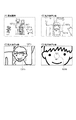
図2(A)は、参考として、赤(R)、青(B)、緑(Gb、Gr)のベイヤー配列例の画像センサー表面の一部の模式図である。図2(B)は、図2(A)のカラーフィルターの配列に対応させて、一つのマイクロレンズに対して光電変換手段としてのフォトダイオードを2つ保持している画素部例である。   FIG. 2A is a schematic diagram of a part of the image sensor surface of an example of Bayer arrangement of red (R), blue (B), and green (Gb, Gr) for reference. FIG. 2B shows an example of a pixel portion in which two photodiodes as photoelectric conversion means are held for one microlens corresponding to the arrangement of the color filters in FIG.

こうした構成を有する画像センサーは、各画素部から位相差検出用の2つの信号(以下、A像信号、B像信号ともいう。)を出力できるようになっている。また、2つのフォトダイオードの信号を加算した撮像の記録用の信号(A像信号+B像信号)も出力できるようになっている。この加算した信号の場合には、図2(A)で概略説明したベイヤー配列例の画像センサーの出力と同等の信号が出力される。   The image sensor having such a configuration can output two signals (hereinafter also referred to as an A image signal and a B image signal) for detecting a phase difference from each pixel unit. Further, an image recording signal (A image signal + B image signal) obtained by adding the signals of the two photodiodes can be output. In the case of this added signal, a signal equivalent to the output of the image sensor of the Bayer array example schematically described in FIG.

このような画像センサーとしての撮像素子102からの出力信号を使って、測距部108が2つの像信号の相関演算を行い、デフォーカス量や各種信頼性などの情報を算出する。デフォーカス量は、A像信号、B像信号のズレに基づき、像面でのデフォーカス量を算出する。デフォーカス量は正負の値を持っており、デフォーカス量が正の値であるか負の値であるかによって、前ピンか後ピンかがわかる。また、デフォーカス量の絶対値によって、合焦までの度合いが分かり、デフォーカス量が0であれば合焦である。すなわち、測距部108は、測距位置(測距領域、焦点検出位置、焦点検出領域)について算出したデフォーカス量の正負を元に前ピンか後ピンかの情報をCPU119aなどに出力する。また、デフォーカス量の絶対値に基づいて、合焦の度合い(ピントのズレの度合い)である合焦度合い情報をCPU119aなどに出力する。前ピンか後ピンかの情報は、デフォーカス量が所定値を超える場合に出力し、デフォーカス量の絶対値が所定値以内である場合には、合焦であるという情報を出力する。なお、合焦度合い情報は、デフォーカス量を、合焦させるまでにフォーカスリング134を回転させる操作量に換算した値として出力する。   Using the output signal from the image sensor 102 as such an image sensor, the distance measuring unit 108 performs correlation calculation between the two image signals, and calculates information such as the defocus amount and various reliability. The defocus amount is calculated based on the deviation between the A image signal and the B image signal. The defocus amount has a positive or negative value, and it can be determined whether the defocus amount is a positive value or a negative value depending on whether the defocus amount is a positive value or a negative value. In addition, the absolute value of the defocus amount indicates the degree of focusing, and if the defocus amount is 0, the focus is achieved. That is, the distance measuring unit 108 outputs information on whether the front pin or the rear pin is based on the sign of the defocus amount calculated for the distance measurement position (range measurement area, focus detection position, focus detection area) to the CPU 119a and the like. Further, based on the absolute value of the defocus amount, focus degree information that is the degree of focus (degree of focus shift) is output to the CPU 119a and the like. Information about whether the front pin or the rear pin is present is output when the defocus amount exceeds a predetermined value, and when the absolute value of the defocus amount is within the predetermined value, information indicating that the focus is achieved is output. The in-focus degree information is output as a value obtained by converting the defocus amount into an operation amount for rotating the focus ring 134 before focusing.

なお、本実施形態は撮像用の信号及び位相差検出用の2つの信号の2つの計3つの信号を撮像素子102から出力している。この点、このような方法に限定されない。例えば、撮像用の信号と位相差AF用の像信号の2つの信号のうちの1つの計2つ信号を出力するようにしてもよい。この場合、出力後に位相差検出用の像信号の2つの信号のうちの他の1つの信号は、撮像素子102からの2つの出力信号を利用して算出される。   In this embodiment, a total of three signals, that is, two signals for imaging and two signals for phase difference detection are output from the imaging element 102. This point is not limited to such a method. For example, a total of two signals out of two signals of an imaging signal and an image signal for phase difference AF may be output. In this case, after output, the other one of the two signals of the image signal for phase difference detection is calculated using the two output signals from the image sensor 102.

また、図2では、一つのマイクロレンズに対して光電変換手段としてのフォトダイオードを2つ保持している画素部をアレイ状に並べている例を示した。この点、一つのマイクロレンズに対して光電変換手段としてのフォトダイオードを3つ以上保持している画素部をアレイ状に並べているようにしてもよい。また、マイクロレンズに対して受光部の開口位置が異なる画素部を複数有するようにしてもよい。つまり、結果としてA像信号とB像信号といった位相差検出可能な位相差検出用の2つの信号が得られるようになっていれば足りる。   FIG. 2 shows an example in which pixel portions holding two photodiodes as photoelectric conversion means are arranged in an array for one microlens. In this regard, pixel portions holding three or more photodiodes as photoelectric conversion means may be arranged in an array for one microlens. Moreover, you may make it have multiple pixel parts from which the opening position of a light-receiving part differs with respect to a micro lens. That is, it is only necessary to obtain two phase difference detection signals capable of detecting a phase difference, such as an A image signal and a B image signal.

図3から図6は、デジタルカメラ10が行う制御を示すフローチャートである。なお、これらフローチャートの動作は、本体マイコン119(より詳細にはCPU119a)がROM119bに記憶されたプログラムに基づいて、デジタルカメラ10の各部を制御することによって実現される。   3 to 6 are flowcharts showing the control performed by the digital camera 10. The operations of these flowcharts are realized by the main body microcomputer 119 (more specifically, the CPU 119a) controlling each part of the digital camera 10 based on a program stored in the ROM 119b.

<撮影モード処理>
図3(A),図3(B)は、デジタルカメラ10が撮影モードにあるときの全体的な動作をしたフローチャートである。デジタルカメラ10を起動して撮影モードに設定すると、図3(A)の処理を開始する。
<Shooting mode processing>
FIGS. 3A and 3B are flowcharts showing the overall operation when the digital camera 10 is in the shooting mode. When the digital camera 10 is activated and set to the photographing mode, the processing of FIG.

S301では、CPU119aは、表示部107に表示する画面種別を決定する。この処理では、顔検出機能のON/OFF,フォーカスの設定がAFであるかMFであるか、AFの結果合焦したか否か、フォーカスアシストの設定のON/OFF、などの情報に基づき、AF枠、顔枠、フォーカスアシスト枠の表示要否及び表示形態を決定する。この処理の詳細は図4を用いて後述する。   In S301, the CPU 119a determines a screen type to be displayed on the display unit 107. In this process, based on information such as ON / OFF of the face detection function, whether the focus setting is AF or MF, whether the AF is in focus, ON / OFF of the focus assist setting, etc. The necessity of display and the display form of the AF frame, the face frame, and the focus assist frame are determined. Details of this processing will be described later with reference to FIG.

S302では、CPU119aは、S301で決定した画面種別が、フォーカスアシスト表示可能な状態の画面であるか否かを判定する。より詳しくは、後述する図4の処理により、フォーカスアシスト表示:あり、となったか否かを判定する。フォーカスアシスト表示可能な状態であればS303へ進み、そうでない場合はS305へ進む。   In S302, the CPU 119a determines whether or not the screen type determined in S301 is a screen in a state where focus assist display is possible. More specifically, it is determined whether or not the focus assist display is present by the processing of FIG. 4 described later. If the focus assist display is possible, the process proceeds to S303, and if not, the process proceeds to S305.

S303では、CPU119aは、Dispレベルが情報非表示状態であるか否かを判定する。Dispレベルとは、撮影画像に重畳して表示する各種情報表示を、どの程度詳細に表示するか、どの種別の情報を表示するかがそれぞれ異なる複数段階の情報表示レベルのことである。Dispレベルが情報非表示状態に設定されている場合には、撮像画像に対してどの情報も表示されない。Dispレベルの設定については、S336で後述する。Dispレベルが情報非表示状態である場合にはS305へ進み、それ以外のDispレベルあればS304へ進む。   In S303, the CPU 119a determines whether or not the Disp level is an information non-display state. The Disp level is a multiple-level information display level in which various information displays to be displayed superimposed on a captured image are displayed in detail, and which type of information is displayed. When the Disp level is set to the information non-display state, no information is displayed on the captured image. The setting of the Disp level will be described later in S336. If the Disp level is in the information non-display state, the process proceeds to S305, and if other Disp level, the process proceeds to S304.

S304では、CPU119aは、フォーカスアシスト表示処理を行う。この処理は、撮影画像のうち特定の箇所(測距位置、焦点検出位置)の被写体について、測距部108から取得した情報に基づいて、合焦度合いと、合焦させるまでの操作方向を示す表示アイテムであるフォーカスアシストを表示する処理である。この処理の詳細は図5を用いて後述する。   In S304, the CPU 119a performs a focus assist display process. This process indicates the degree of focusing and the operation direction until focusing is performed on the subject at a specific location (ranging position, focus detection position) in the captured image based on information acquired from the ranging section 108. This is processing for displaying focus assist, which is a display item. Details of this processing will be described later with reference to FIG.

S305では、CPU119aは、フォーカスアシスト表示を行わずに、ライブビュー画像を表示部107に表示する。ライブビュー画像とは、撮像素子102で撮像され、画像処理部118でライブビュー用の画像処理を施された撮像画像であり、所定のフレームレートで逐次更新される画像のことである。   In S305, the CPU 119a displays the live view image on the display unit 107 without performing the focus assist display. The live view image is a captured image captured by the image sensor 102 and subjected to image processing for live view by the image processing unit 118, and is an image that is sequentially updated at a predetermined frame rate.

S306では、CPU119aは、ダイヤル126が操作されたか否かを判定する(移動指示受付)。ダイヤル126が操作された場合はS307へ進み、そうでない場合はS308へ進む。   In S306, the CPU 119a determines whether or not the dial 126 has been operated (movement instruction reception). If the dial 126 is operated, the process proceeds to S307, and if not, the process proceeds to S308.

S307は、ダイヤル126の操作に基づいて、測距位置(測距領域、焦点検出位置、焦点検出領域)をジャンプ(複数の特定箇所の何れかに移動)する。例えば、映像を縦横に黄金比(およそ5:8)に分割した交点4箇所のうち、直前の測距位置に最も近い交点からダイヤル126の回転方向に応じた次の交点の位置へジャンプ(測距位置を変更)する。移動した測距位置で、RAM119cに保持された測距位置を更新する。測距位置が移動すると、フォーカスアシストの表示位置も測距位置に連動して移動する。一般に、映像中において主要な被写体を黄金比の交点に配置すると構図が安定するとされている。そのため、黄金比を意識した撮影を行っている場合には、上述の交点4箇所のいずれかに、焦点調節を行うべき被写体を配置している可能性が高い。このように、ダイヤル126の操作に応じて測距位置を黄金比の交点に順次ジャンプするようにすれば、黄金比の交点に配置した焦点調節を行いたい被写体の位置に素早く測距位置を変更することができる。なお、S306、S307の処理は、黄金比の補助線(グリッドライン)を表示している動作モードの場合にのみ行い、そうでない場合には黄金比を意識した撮影とは限らないのでダイヤル126を操作しても測距位置をジャンプしない構成としても良い。また、黄金比の交点に限らず、3分割線の交点や、画面中央などにジャンプするようにしても良い。さらに、表示しているグリッドラインの種別に応じて異なる位置にジャンプするようにしても良い。例えば、黄金比のグリッドラインを表示している場合にはダイヤル126の操作に応じて上述のように黄金比の交点に順次測距位置を移動させる。一方、3分割のグリッドラインを表示している場合にはダイヤル126の操作に応じて3分割線の交点に順次測距位置を移動させる。   In step S307, based on the operation of the dial 126, the distance measurement position (range measurement area, focus detection position, focus detection area) is jumped (moved to any one of a plurality of specific locations). For example, among the four intersections obtained by dividing the image vertically and horizontally into a golden ratio (approximately 5: 8), jump from the intersection closest to the previous distance measurement position to the position of the next intersection according to the rotation direction of the dial 126 (measurement). Change the distance position). The distance measurement position held in the RAM 119c is updated with the moved distance measurement position. When the distance measurement position moves, the focus assist display position also moves in conjunction with the distance measurement position. In general, it is considered that the composition is stable when the main subject is arranged at the intersection of the golden ratio in the video. For this reason, when photographing taking account of the golden ratio, there is a high possibility that a subject to be subjected to focus adjustment is placed at any of the four intersections described above. In this way, if the distance measuring position is sequentially jumped to the intersection of the golden ratio according to the operation of the dial 126, the distance measuring position is quickly changed to the position of the subject to be focused at the intersection of the golden ratio. can do. Note that the processing of S306 and S307 is performed only in the operation mode in which the golden ratio auxiliary line (grid line) is displayed. Otherwise, the photographing is not necessarily conscious of the golden ratio. A configuration may be adopted in which the distance measurement position is not jumped even when operated. Further, the jump is not limited to the intersection of the golden ratios, but may be made to jump to the intersection of three dividing lines or the center of the screen. Furthermore, you may make it jump to a different position according to the kind of displayed grid line. For example, when the golden ratio grid line is displayed, the distance measurement position is sequentially moved to the intersection of the golden ratio as described above according to the operation of the dial 126. On the other hand, when a three-divided grid line is displayed, the distance measurement position is sequentially moved to the intersection of the three-divided lines according to the operation of the dial 126.

S308では、CPU119aは、十字キー125が操作されたか否かを判定する(移動指示受付)。十字キー125が操作された場合にはS309へ進み、そうでない場合はS310へ進む。   In S308, the CPU 119a determines whether or not the cross key 125 has been operated (movement instruction reception). If the cross key 125 is operated, the process proceeds to S309, and if not, the process proceeds to S310.

S309は、CPU119aは、十字キー125のうち操作されたキーに対応する方向(上下左右の何れかの方向)へ測距位置を一定量移動する。移動した測距位置で、RAM119cに保持された測距位置を更新する。測距位置を移動すると、フォーカスアシスト表示の位置も連動して移動させる。十字キー125が操作され続けた場合(所定時間以上継続して押下された場合)は長さに応じて測距位置の移動速度を加速するようにしてもよい。このようにすると、移動前の測距位置から離れた位置の被写体に対しても素早く測距位置を移動することができる。ダイヤル126の操作に応じた測距位置の移動が、複数の予め定まった位置の何れかに測距位置をジャンプさせる移動であるのに対し、十字キー125の操作に応じた測距位置の移動は、ユーザー画面上の任意の位置に測距位置を移動させる操作である。また、画像処理部118で顔検出制御が行われていれば、十字キー125の操作方向に存在する、検出された顔の位置へ測距位置を移動するようにしてもよい。このようにすれば、離れた顔に対しても即座に測距位置を当てることができる。   In step S309, the CPU 119a moves the distance measurement position by a certain amount in a direction corresponding to the operated key of the cross key 125 (any one of up, down, left, and right directions). The distance measurement position held in the RAM 119c is updated with the moved distance measurement position. When the distance measurement position is moved, the position of the focus assist display is also moved in conjunction with it. When the cross key 125 is continuously operated (when the cross key 125 is continuously pressed for a predetermined time or more), the moving speed of the distance measurement position may be accelerated according to the length. In this way, the distance measurement position can be quickly moved even with respect to the subject at a position away from the distance measurement position before the movement. While the movement of the distance measurement position according to the operation of the dial 126 is a movement for jumping the distance measurement position to any of a plurality of predetermined positions, the movement of the distance measurement position according to the operation of the cross key 125 is performed. Is an operation of moving the ranging position to an arbitrary position on the user screen. If the image processing unit 118 performs face detection control, the distance measurement position may be moved to the detected face position that exists in the direction of operation of the cross key 125. In this way, the distance measuring position can be immediately applied to a distant face.

なお、S306〜S309で説明したようにユーザーの操作に応じて測距位置を移動できるのは、S314で後述する顔検出機能がOFFとなっている場合に限るものとする。顔検出機能がONとなっている場合には、検出された顔のうち、主顔と判定されている顔の位置に測距位置を連動させる。そのため、顔検出機能がONとなっている場合はユーザーによるダイヤル126の操作や十字キー125の操作が行われても測距位置を移動しない。   Note that, as described in S306 to S309, the distance measurement position can be moved according to the user's operation only when the face detection function described later in S314 is OFF. When the face detection function is ON, the distance measurement position is linked to the position of the face determined as the main face among the detected faces. Therefore, when the face detection function is ON, the distance measurement position is not moved even if the user operates the dial 126 or the cross key 125.

S310では、CPU119aは、メニューキー124が押下されたか否かを判定する。メニューキー124が押下された場合はS311へ進み、そうでない場合は図3(B)のS324へ進む。   In S310, the CPU 119a determines whether the menu key 124 has been pressed. If the menu key 124 is pressed, the process proceeds to S311. Otherwise, the process proceeds to S324 in FIG.

S311は、CPU119aは、表示部107に、デジタルカメラ10に関する設定項目(メニュー項目)を一覧したメニュー画面を表示する。メニュー画面内では、十字キー125またはダイヤル126によってメニュー項目の何れかを選択し、SETキー127で選択や確定の操作を行うことによって、デジタルカメラ10の各種機能の設定を変更することができる。   In S <b> 311, the CPU 119 a displays a menu screen that lists setting items (menu items) related to the digital camera 10 on the display unit 107. In the menu screen, setting of various functions of the digital camera 10 can be changed by selecting any of the menu items with the cross key 125 or the dial 126 and performing a selection or confirmation operation with the SET key 127.

S312は、CPU119aは、フォーカスアシスト機能のON/OFF設定を切り替えるメニュー項目が選択され、その項目からフォーカスアシスト機能のON/OFFの切替操作が行われたか否かを判定する。フォーカスアシスト機能のON/OFFの切替操作が行われた場合はS313へ進み、そうでない場合はS314へ進む。   In step S312, the CPU 119a determines whether a menu item for switching ON / OFF of the focus assist function is selected, and whether or not the focus assist function ON / OFF switching operation is performed from that item. If the focus assist function ON / OFF switching operation has been performed, the process proceeds to S313, and if not, the process proceeds to S314.

S313では、CPU119aは、フォーカスアシスト機能のON/OFF設定(アシスト表示の表示設定)を変更する。フォーカスアシスト機能がONに設定された場合は、ONに設定されていることを示す情報をROM119bに記録する。フォーカスアシスト機能がOFFに設定された場合は、OFFに設定されていることを示す情報をROM119bに記録する。このようにメニューの設定項目からフォーカスアシスト機能をOFFにした場合は、いずれの場合でもフォーカスアシスト表示を行わない。一方、メニューの設定項目からフォーカスアシスト機能をONにした場合には、常にフォーカスアシストが表示されるわけではなく、AF設定かMF設定かといった条件や、Dispレベルなどの各種条件に基づき、状況によってフォーカスアシスト表示を行う。   In S313, the CPU 119a changes ON / OFF setting (assist display display setting) of the focus assist function. When the focus assist function is set to ON, information indicating that the focus assist function is set to ON is recorded in the ROM 119b. When the focus assist function is set to OFF, information indicating that the focus assist function is set to OFF is recorded in the ROM 119b. As described above, when the focus assist function is turned off from the setting item of the menu, the focus assist display is not performed in any case. On the other hand, when the focus assist function is turned on from the menu setting item, the focus assist is not always displayed, and depending on the situation based on conditions such as AF setting or MF setting and various conditions such as the Disp level. Perform focus assist display.

S314では、CPU119aは、顔検出機能のON/OFF設定を切り替えるメニュー項目が選択され、その項目から顔検出機能のON/OFFの切替操作が行われたか否かを判定する。切替操作が行われた場合はS315に進み、そうでない場合はS316へ進む。   In S <b> 314, the CPU 119 a determines whether a menu item for switching ON / OFF of the face detection function is selected, and whether the operation for switching ON / OFF of the face detection function has been performed from that item. If the switching operation has been performed, the process proceeds to S315, and if not, the process proceeds to S316.

S315では、CPU119aは、顔検出機能のON/OFF設定の切替操作に基づき、顔検出機能をONまたはOFFに設定し、設定された状態を示す情報をROM119bに記録する。顔検出機能がONになった場合は、撮像されているライブビュー画像(撮影画像)から人物の顔(特定の被写体)の領域を検出する。検出された顔の領域には顔枠を付して表示する。また、AFに設定されている場合には、検出された複数の顔のうち、サイズが大きい、画面中央に近い、登録されている特定個人であると個人認識された等の条件に基づいてもっとも主要な顔と判定された顔(主顔)にAF(顔AF)する。顔検出機能がONに設定され、顔が検出出来た場合には、測距位置を、主顔の位置で上書きする。すなわち、後述するフォーカスアシストを行う位置を、検出された主顔の位置に連動させる。   In S315, the CPU 119a sets the face detection function to ON or OFF based on the face detection function ON / OFF setting switching operation, and records information indicating the set state in the ROM 119b. When the face detection function is turned on, the area of the person's face (specific subject) is detected from the captured live view image (captured image). The detected face area is displayed with a face frame. In addition, when the AF is set, the size of the detected faces is large, close to the center of the screen, or personally recognized as a registered specific individual. AF (face AF) is performed on the face (main face) determined to be the main face. When the face detection function is set to ON and a face can be detected, the distance measurement position is overwritten with the position of the main face. That is, a position for performing focus assist described later is linked to the detected position of the main face.

S316は、AFモード設定を変更するメニュー項目が選択され、AFモードの変更操作が行われたか否かを判定する。本実施形態においては、AFモードとしてワンショットAFとコンティニュアスAFの2つがあるものとする。ワンショットAFは、ユーザーがワンショットAFキー129を1回押下したことに応じて1回のAFを行い、それ以外の場合はフォーカス位置を動かさない動作モードである。ワンショットAFキー129の押下の度にAFを行う。一方コンティニュアスAFは、所定の被写体に対して合焦するように継続してAFを行い続ける動作モードである、ユーザーが操作を行わなくとも、合焦させるべき被写体が動いた場合やデジタルカメラ10が移動した場合にはフォーカス位置が随時調整される。なお、本実施形態ではAFモードとしてこの2種類を例に挙げるが、これに限るものではなく、他のAFモードを選択可能であっても良い。AFモードの変更操作が行われた場合にはS317へ進み、そうでない場合はS320へ進む。   In step S316, it is determined whether a menu item for changing the AF mode setting has been selected and an AF mode changing operation has been performed. In the present embodiment, it is assumed that there are two AF modes, one-shot AF and continuous AF. One-shot AF is an operation mode in which one AF is performed in response to the user pressing the one-shot AF key 129 once, and the focus position is not moved in other cases. AF is performed each time the one-shot AF key 129 is pressed. On the other hand, continuous AF is an operation mode in which AF is continuously performed so that a predetermined subject is focused. When the subject to be focused moves without a user operation, a digital camera When 10 moves, the focus position is adjusted at any time. In the present embodiment, these two types are exemplified as AF modes. However, the present invention is not limited to this, and other AF modes may be selectable. If an AF mode change operation has been performed, the process proceeds to S317, and if not, the process proceeds to S320.

S317では、CPU119aは、AFモードの変更操作に応じて、ユーザーに選択されたAFモード(本実施形態ではワンショットAFとコンティニュアスAFの何れか)に設定する。そして、設定されたAFモードを示す情報を、ROM119bに記録する。   In S317, the CPU 119a sets the AF mode selected by the user (in this embodiment, one-shot AF or continuous AF) according to the AF mode changing operation. Then, information indicating the set AF mode is recorded in the ROM 119b.

S318では、CPU119aは、画像サイズ設定のメニュー項目が選択され、画像サイズ設定の変更操作が行われたか否かを判定する。画像サイズ設定の変更が行われた場合はS319へ進み、そうでない場合はS320へ進む。   In step S318, the CPU 119a determines whether an image size setting menu item has been selected and an image size setting change operation has been performed. If the image size setting has been changed, the process proceeds to S319, and if not, the process proceeds to S320.

S319は、CPU119aは、ユーザーの操作に応じて画像サイズ設定を変更する。変更された画像サイズ設定の設定値を示す情報を、ROM119bに記録する。撮影・記録が行われた場合、ここで設定された画像サイズで記録される。なお、この処理の詳細は図6を用いて後述する。   In S319, the CPU 119a changes the image size setting according to the user's operation. Information indicating the set value of the changed image size setting is recorded in the ROM 119b. When shooting / recording is performed, the image is recorded with the image size set here. Details of this processing will be described later with reference to FIG.

S320は、CPU119aは、メニュー画面において、上述のS312〜S319で説明した設定項目以外の設定項目に関して、設定変更操作が行われたか否かを判定する。設定変更操作があった場合はS321へ進み、そうでない場合はS322へ進む。S321では、CPU119aは、S320で行われた操作に応じて設定を変更する。   In S320, the CPU 119a determines whether or not a setting change operation has been performed on setting items other than the setting items described in S312 to S319 described above on the menu screen. If there is a setting change operation, the process proceeds to S321, and if not, the process proceeds to S322. In S321, the CPU 119a changes the setting according to the operation performed in S320.

S322では、CPU119aは、メニュー画面を閉じる操作が行われたか否かを判定する。メニュー画面を閉じる操作とは、メニューキー124が押下されるか、メニューの初期画面でキャンセルキー128を押下するか、もしくはメニュー終了の項目を選択した状態でSETキー127を押下するかのいずれかの操作である。メニュー画面を閉じる操作が行われた場合はS323に進み、そうでない場合はS312に戻って処理を繰り返す。   In S322, the CPU 119a determines whether or not an operation for closing the menu screen has been performed. The operation of closing the menu screen is either pressing the menu key 124, pressing the cancel key 128 on the initial menu screen, or pressing the SET key 127 with the menu end item selected. Operation. If an operation to close the menu screen is performed, the process proceeds to S323, and if not, the process returns to S312 and the process is repeated.

S323では、CPU119aは、メニュー画面表示を終了し、ライブビュー画面を再表示し、図3(B)のS324に進む。   In S323, the CPU 119a ends the menu screen display, redisplays the live view screen, and proceeds to S324 in FIG.

図3(B)のS324では、CPU119aは、AF/MFスイッチ135によってAFとMFの切替操作が行われたか否かを判定する。AFとMFの切替が行われた場合はS325に進み、そうでない場合はS326へ進む。   In S324 of FIG. 3B, the CPU 119a determines whether or not the AF / MF switch 135 has performed switching operation between AF and MF. If switching between AF and MF is performed, the process proceeds to S325, and if not, the process proceeds to S326.

S325では、CPU119aは、AF/MFスイッチ135の操作に応じてAFとMFを切り替える。AFに切り替えられた場合には、AFに切り替えられた旨を示す情報をROM119bに記録し、AF設定での動作を開始する。AF設定に切り替えられた場合は、前述のワンショットAFモードとコンティニュアスAFモードとのうち、現在のAFモードが示すモードの動作を行う。   In S325, the CPU 119a switches between AF and MF in accordance with the operation of the AF / MF switch 135. When switched to AF, information indicating that the mode has been switched to AF is recorded in the ROM 119b, and the operation with AF setting is started. When the AF setting is switched, the operation of the mode indicated by the current AF mode is performed among the one-shot AF mode and the continuous AF mode described above.

S326では、CPU119aは、AF/MFスイッチ135でAFに設定されており、かつ、AFモードがワンショットAFモードであるか否かを判定する。真であればS327へ、そうでない場合はS329へ進む。   In S326, the CPU 119a determines whether or not the AF / MF switch 135 is set to AF and the AF mode is the one-shot AF mode. If true, the process proceeds to S327, and if not, the process proceeds to S329.

S327は、CPU119aは、ワンショットAFキー129が押下されたか否かを判定する(AF実行指示の受付)。ワンショットAFキー129が押下された場合はS328へ進み、そうでない場合はS329へ進む。   In S327, the CPU 119a determines whether or not the one-shot AF key 129 has been pressed (accepting an AF execution instruction). If the one-shot AF key 129 is pressed, the process proceeds to S328, and if not, the process proceeds to S329.

S328では、CPU119aは、AF枠に対応する測距位置の被写体が合焦するように、フォーカス制御部113を制御してAFを行う。   In S328, the CPU 119a performs AF by controlling the focus control unit 113 so that the subject at the distance measurement position corresponding to the AF frame is in focus.

S329では、CPU119aは、AF/MFスイッチ135でAFに設定されており、かつ、AFモードがコンティニュアスAFモードであるか否かを判定する。真であればS330へ進み、そうでない場合はS335へ進む。   In S329, the CPU 119a determines whether or not the AF / MF switch 135 is set to AF and the AF mode is the continuous AF mode. If true, the process proceeds to S330, and if not, the process proceeds to S335.

S330では、CPU119aは、AFロックキー130の押下によってAFロック状態にあるか否かを判定する。AFロック状態であればS331へ進み、そうでない場合はS332へ進む。AFロック状態では、コンティニュアスAFを行う動作モード中に、一時的にAFを行わずにフォーカス位置を固定している状態である。   In S330, the CPU 119a determines whether or not the AF lock state is established by pressing the AF lock key 130. If it is in the AF lock state, the process proceeds to S331, and if not, the process proceeds to S332. The AF lock state is a state in which the focus position is fixed without performing AF temporarily during the operation mode in which continuous AF is performed.

S331では、CPU119aは、AFロックキー130が押下されたか否かを判定する(停止指示または解除指示の受付)。AFロックキー130が押下された場合はS332へ進み、そうでない場合はS335へ進む。   In S331, the CPU 119a determines whether or not the AF lock key 130 is pressed (accepts a stop instruction or a release instruction). If the AF lock key 130 is pressed, the process proceeds to S332, and if not, the process proceeds to S335.

S332では、CPU119aは、AFロック状態を解除し、コンティニュアスAFを行い、AF枠に対応する被写体が合焦するようフォーカス制御部113を継続して制御する。   In S332, the CPU 119a releases the AF lock state, performs continuous AF, and continuously controls the focus control unit 113 so that the subject corresponding to the AF frame is in focus.

S333では、CPU119aは、AFロックキー130が押下されたか否かを判定する。AFロックキー130が押下された場合はS334へ進み、そうでない場合はS335へ進む。   In S333, the CPU 119a determines whether or not the AF lock key 130 has been pressed. If the AF lock key 130 is pressed, the process proceeds to S334, and if not, the process proceeds to S335.

S334では、CPU119aは、コンティニュアスAFを停止し、AFをロックする(AFロック状態にする)。すなわちフォーカス制御部113によるAF制御を停止する。これによってAFによるフォーカス位置の変更は停止されるが、フォーカスリング134の操作によるマニュアルフォーカスは可能である。   In S334, the CPU 119a stops the continuous AF and locks the AF (sets the AF lock state). That is, the AF control by the focus control unit 113 is stopped. As a result, the change of the focus position by AF is stopped, but manual focus by operating the focus ring 134 is possible.

S335では、CPU119aは、DISPLAYキー132が押下されたか否かを判定する。DISPLAYキー132が押下された場合はS336へ進み、そうでない場合はS337へ進む。   In S335, the CPU 119a determines whether or not the DISPLAY key 132 has been pressed. If the DISPLAY key 132 is pressed, the process proceeds to S336, and if not, the process proceeds to S337.

S336では、CPU119aは、DISPLAYキー132の押下に応じてDispレベルを切り替える。変更されたDispレベルをROM119bに記録し、変更されたDispレベルに応じた情報表示を行う。   In S336, the CPU 119a switches the Disp level in response to pressing of the DISPLAY key 132. The changed Disp level is recorded in the ROM 119b, and information display according to the changed Disp level is performed.

S337では、CPU119aは、拡大キー131が押下されたか否かを判定する。拡大キー131が押下された場合はS338へ進み、そうでない場合はS339へ進む。   In S337, the CPU 119a determines whether or not the enlargement key 131 has been pressed. If the enlargement key 131 is pressed, the process proceeds to S338, and if not, the process proceeds to S339.

S338では、CPU119aは、拡大処理を行う。この処理の詳細は図7を用いて後述する。   In S338, the CPU 119a performs enlargement processing. Details of this processing will be described later with reference to FIG.

S339では、CPU119aは、START/STOPキー133が押下されたか否かを判定する。START/STOPキー133が押下された場合はS340へ進み、そうでない場合はS343へ進む。   In S339, the CPU 119a determines whether or not the START / STOP key 133 has been pressed. If the START / STOP key 133 is pressed, the process proceeds to S340; otherwise, the process proceeds to S343.

S340では、CPU119aは、動画の記録動作中(撮影記録中)であるか否かを判定する。記録動作中あればS342へ進み、そうでない場合(撮影待機中である場合)はS341へ進む。   In S340, the CPU 119a determines whether or not the moving image recording operation is being performed (during shooting recording). If the recording operation is in progress, the process proceeds to S342, and if not (when shooting is in standby), the process proceeds to S341.

S341では、CPU119aは、動画記録を開始する。すなわち、撮像素子102で撮像され、画像処理部118で記録用に処理された動画を、所定のファイルフォーマットに従って記録媒体105に動画ファイルとして記録していく。   In S341, the CPU 119a starts moving image recording. That is, a moving image captured by the image sensor 102 and processed for recording by the image processing unit 118 is recorded as a moving image file on the recording medium 105 in accordance with a predetermined file format.

S342では、CPU119aは、動画記録を停止する。動画記録を停止すると、記録していた動画ファイルに対して属性付与を行ったり、ファイルをクローズするなどの動画終了処理を行う。   In S342, the CPU 119a stops moving image recording. When the moving image recording is stopped, the moving image ending process such as adding an attribute to the recorded moving image file or closing the file is performed.

S343では、CPU119aは、上記のステップで挙げたイベント以外のイベントが発生したか否かを判定する。その他のイベントがあった場合はS344へ進み、そうでない場合はS345へ進む。S344では、CPU119aは、S343で発生したイベントに対応する処理を行う。   In S343, the CPU 119a determines whether an event other than the events listed in the above steps has occurred. If there is another event, the process proceeds to S344, and if not, the process proceeds to S345. In S344, the CPU 119a performs processing corresponding to the event that occurred in S343.

S345では、CPU119aは、撮影モード処理を終了するイベントがあったか否かを判定する。終了イベントがあった場合は撮影モードを終了し、そうでない場合は、S301に戻って処理を繰り返す。終了イベントには、例えば、デジタルカメラ10の電源をオフにする操作、電源電圧低下による電源オフ、撮影待機状態で所定時間無操作だったことに応じたオートパワーオフ、再生モードや通信モードなど撮影モード以外の動作モードに移行する操作などがある。   In S345, the CPU 119a determines whether or not there is an event for ending the shooting mode process. If there is an end event, the shooting mode is ended. If not, the process returns to S301 to repeat the process. The end event includes, for example, an operation for turning off the power of the digital camera 10, a power off due to a power supply voltage drop, an auto power off in response to no operation for a predetermined time in a shooting standby state, a shooting mode such as a playback mode and a communication mode. There is an operation to shift to an operation mode other than the mode.

なお、ユーザーの操作に応じて測距位置を移動できるのは、S314で設定される顔検出機能がOFFとなっている場合に限るものとしたが、顔検出機能がONとなっている場合にもユーザーの操作に応じて測距位置を移動できるようにしてもよい。この場合、S306〜S309で説明したような測距位置を移動させるユーザー操作が行われる前は、測距位置は検出された主顔の位置に連動させる。そして、測距位置を移動させるユーザー操作が行われた場合は、測距位置を主顔の位置と連動することなく、ユーザーの操作に応じて移動させる。ユーザー操作に応じて移動させた後は、測距位置は主顔の位置とは連動しない。その後、測距位置と主顔の位置を連動させる状態に復帰させる復帰操作(リセット操作)が行われると、再び測距位置が主顔の位置となり、その後は測距位置を主顔の位置に連動させる。リセット操作としては、例えばキャンセルキー128を押下するなどが考えられる。この場合、後述するS312でフォーカスアシスト機能をONにしており、フォーカスアシストを表示していた場合には、測距位置と主顔の位置が連動している場合には主顔を示す顔枠は表示しない。測距位置を移動させるユーザー操作が行われた場合は、測距位置を主顔の位置と連動することなく、ユーザーの操作に応じて移動させ、フォーカスアシストの位置も合わせて移動する。それとともに、主顔の位置に主顔を示す顔枠を新たに表示させる。その後復帰操作によって測距位置を主顔の位置に再度連動させると、主顔を示す顔枠を非表示とする。   Note that the distance measurement position can be moved according to the user's operation only when the face detection function set in S314 is OFF, but when the face detection function is ON. Alternatively, the distance measurement position may be moved according to the user's operation. In this case, before the user operation for moving the distance measurement position as described in S306 to S309 is performed, the distance measurement position is linked to the detected position of the main face. When a user operation for moving the distance measurement position is performed, the distance measurement position is moved according to the user operation without being linked to the position of the main face. After being moved according to the user operation, the distance measuring position is not linked with the position of the main face. After that, when a return operation (reset operation) is performed to return the distance measurement position to the main face position, the distance measurement position becomes the main face position again. After that, the distance measurement position becomes the main face position. Interlock. As the reset operation, for example, pressing the cancel key 128 can be considered. In this case, when the focus assist function is turned on in S312 described later and focus assist is displayed, the face frame indicating the main face is displayed when the distance measurement position and the main face position are linked. Do not show. When a user operation for moving the distance measurement position is performed, the distance measurement position is moved in accordance with the user operation without being linked with the position of the main face, and the focus assist position is also moved. At the same time, a face frame indicating the main face is newly displayed at the position of the main face. Thereafter, when the distance measurement position is linked again to the position of the main face by the return operation, the face frame indicating the main face is not displayed.

<画像種別決定処理>
図3(A)のS301で説明した画面種別決定処理の詳細について説明する。まず各種画面種別について説明する。図11(A)〜(G)に、各種表示状態(各種画面種別)の表示部107への表示例を示す。なお、図11(A)〜(G)では省略しているが、Dispレベルが情報非表示以外の場合には、フォーカスアシスト、AF枠(AF領域)、顔枠以外の、Dispレベルに応じた情報がライブビューに重畳して表示される。顔枠以外の、Dispレベルに応じた情報には、グリッドライン、電池残量、残り撮影可能時間等などがある。なお、以下では、S314、S315で説明した顔検出機能がONに設定されている場合を単に顔検出ON、OFFに設定されている場合を単に顔検出OFFと称する。
<Image type determination process>
Details of the screen type determination process described in S301 of FIG. First, various screen types will be described. FIGS. 11A to 11G show display examples on the display unit 107 of various display states (various screen types). Although not shown in FIGS. 11A to 11G, when the Disp level is other than information non-display, it corresponds to the Disp level other than the focus assist, the AF frame (AF area), and the face frame. Information is displayed superimposed on the live view. The information according to the Disp level other than the face frame includes a grid line, a remaining battery level, a remaining shooting time, and the like. Hereinafter, the case where the face detection function described in S314 and S315 is set to ON is simply referred to as face detection ON, and the case where the face detection function is set to OFF is simply referred to as face detection OFF.

図11(A)は、顔検出OFFかつMF設定かつフォーカスアシスト機能の設定OFFの場合、及び、顔検出OFFかつAF設定かつワンショットAFモードかつフォーカスアシスト機能の設定OFFの場合の表示例である。このとき、表示部107にはライブビューが表示され、フォーカスアシスト、AF枠、顔枠は表示されない。   FIG. 11A is a display example when face detection is OFF, MF setting, and focus assist function setting are OFF, and when face detection is OFF, AF setting, one-shot AF mode, and focus assist function setting is OFF. . At this time, the live view is displayed on the display unit 107, and the focus assist, the AF frame, and the face frame are not displayed.

図11(B)は、顔検出OFFかつフォーカスアシスト機能の設定ONという条件に加え、MF設定であるか、ワンショットAFモードにおけるAF動作前か、コンティニュアスAFモードにおけるAFロック状態である場合の表示例である。表示部107には、ライブビュー画像に重畳して、フォーカスアシスト1101が表示されている。フォーカスアシスト1101は、フォーカスアシスト1101が表示されている位置(測距位置、焦点検出位置)の被写体について合焦しているか否か、前ピンか後ピンか、合焦度合い(ピントのズレの度合い)を示す表示アイテムである。ユーザーはMFの操作を行う際に、フォーカスアシスト1101を参考にして調整操作を行うことができる。フォーカスアシスト1101の詳細については図8を用いて後述する。   FIG. 11B shows a case where the face detection is OFF and the focus assist function is set to ON, in addition to the MF setting, before the AF operation in the one-shot AF mode, or in the AF lock state in the continuous AF mode. Is a display example. The display unit 107 displays a focus assist 1101 superimposed on the live view image. The focus assist 1101 determines whether the subject at the position (ranging position, focus detection position) where the focus assist 1101 is displayed is in focus, whether it is the front pin or the rear pin, and the degree of focus (degree of focus deviation). ) Is a display item. The user can perform an adjustment operation with reference to the focus assist 1101 when operating the MF. Details of the focus assist 1101 will be described later with reference to FIG.

図11(C)は、顔検出OFFかつワンショットAFモードまたはコンティニュアスAFモードでAF動作を行っている最中、あるいは顔検出OFFかつワンショットAFモードでAF動作を行った後の表示部107における表示例である。AF制御(AF動作)の対象となる被写体領域(測距位置、AF位置、焦点検出位置)とAFの制御状態を、AF枠1102を表示することで示している。AF枠1102の位置が、AF動作の対象となる被写体領域(測距位置、AF位置)を示している。AF枠1102の色は、AFの動作状態を示しており、コンティニュアスAFの実行中(連続してAFが動作している状態)とワンショットAFの実行開始から合焦するまでの間は白色で表示され、ワンショットAFの実行により合焦した場合には緑色で表示される。   FIG. 11C shows the display unit during face detection OFF and AF operation in one-shot AF mode or continuous AF mode, or after AF operation in face detection OFF and one-shot AF mode. FIG. A subject area (ranging position, AF position, focus detection position) to be subjected to AF control (AF operation) and an AF control state are indicated by displaying an AF frame 1102. The position of the AF frame 1102 indicates the subject area (ranging position, AF position) that is the target of the AF operation. The color of the AF frame 1102 indicates the AF operation state. During continuous AF (continuous AF operation) and from the start of execution of one-shot AF to focusing. It is displayed in white, and is displayed in green when in-focus by executing one-shot AF.

図11(D)は、AF/MF設定がAFに設定されていて、コンティニュアスAFモードでAFロック状態となった場合に、フォーカスアシスト機能の設定がOFFである場合の表示例である。ライブビュー画像に重畳してAF枠1103が灰色で表示され、AF動作が行われていないことを示している。   FIG. 11D shows a display example when the AF / MF setting is set to AF and the setting of the focus assist function is OFF when the AF lock state is set in the continuous AF mode. The AF frame 1103 is displayed in gray superimposed on the live view image, indicating that the AF operation is not performed.

図11(E)は、顔検出ONかつワンショットAFモードまたはコンティニュアスAFモードにおいてAF動作を行っている最中か、AF動作を行った後の表示例である。ライブビューに対して顔枠1104、1105、1106が重畳して表示されている。顔枠1104〜1106は、撮像画像から検出された顔の位置に表示される。顔枠1106は、検出された顔のうち、顔AFの対象となる顔(主顔)を示す枠であり、顔枠1104と1105は主顔以外の顔(副顔)を示す枠である。主顔の顔枠1106と副顔の顔枠1104、1105とは表示形態が異なりなり、顔枠1106が主顔を示す顔枠であることが識別できるようになっている。例えば色や、1重線か2重線かなどで表示形態を異ならせており、図示の例では、枠の左右の三角形にて主顔の枠であることを表している。枠の左右の三角形は、左右キーの押下によって(すなわちユーザーの操作に応じて)、主顔を他の顔に変更できることを示している。つまり、本実施形態では、検出された複数の顔のうち、顔AFの対象となる主顔をユーザーが指定することも可能である(複数検出された特定の被写体領域のうち、AF対象となる領域を選択可能)。AFの動作状況を表すため、AFの対象になっていない副顔の顔枠1104、1105は灰色で表示される。主顔を示す顔枠1106は、ワンショットAFまたはコンティニュアスAFでのAF実行中には白色で表示され。ワンショットAFによる顔AFで合焦した場合には緑色で表示される。   FIG. 11E shows a display example during the AF operation in the face detection ON and AF operation in the one-shot AF mode or continuous AF mode. Face frames 1104, 1105, and 1106 are displayed superimposed on the live view. Face frames 1104 to 1106 are displayed at the positions of the faces detected from the captured image. The face frame 1106 is a frame indicating a face (primary face) to be subjected to face AF among the detected faces, and the face frames 1104 and 1105 are frames indicating faces (sub-faces) other than the main face. The main face face frame 1106 and the sub-face face frames 1104 and 1105 are displayed in different forms so that the face frame 1106 can be identified as a face frame indicating the main face. For example, the display form is different depending on color, single line or double line, and in the illustrated example, the right and left triangles of the frame indicate the main face frame. The left and right triangles of the frame indicate that the main face can be changed to another face by pressing the left and right keys (that is, according to the user's operation). That is, in the present embodiment, the user can also specify the main face that is the target of the face AF among the plurality of detected faces (of the plurality of detected specific subject areas, which are AF targets). Area can be selected). In order to represent the AF operation status, the face frames 1104 and 1105 of the sub-faces not targeted for AF are displayed in gray. A face frame 1106 indicating the main face is displayed in white during AF execution in one-shot AF or continuous AF. When in-focus with face AF by one-shot AF, it is displayed in green.

図11(F)は、顔検出ONかつフォーカスアシスト機能の設定がOFFという条件に加え、MF設定であるか、ワンショットAFモードでAFを実行する前か、コンティニュアスAFモードでAFロック状態である場合の表示例である。顔枠1104、1105は副顔を示す顔枠であり、顔枠1107は主顔を示す顔枠である。ただしこの場合、顔枠1107に対してAFの動作は行われていない。この場合、主顔を示す顔枠1107も副顔を示す顔枠1104、1105も、AF動作をしていないことを表すために灰色で表示される。ただし、顔枠1107は主顔であることがわかる表示形態になっている(顔枠1107の左右の三角形が主顔の顔枠であることを示している)。   In FIG. 11F, in addition to the condition that face detection is ON and the setting of the focus assist function is OFF, the MF is set, before AF is executed in the one-shot AF mode, or in the AF lock state in the continuous AF mode. It is a display example in the case of. Face frames 1104 and 1105 are face frames indicating sub-faces, and face frame 1107 is a face frame indicating the main face. However, in this case, the AF operation is not performed on the face frame 1107. In this case, both the face frame 1107 indicating the main face and the face frames 1104 and 1105 indicating the sub-face are displayed in gray to indicate that the AF operation is not performed. However, the face frame 1107 has a display form that indicates that it is the main face (the left and right triangles of the face frame 1107 indicate that it is the main face face frame).

図11(G)は、顔検出がONかつフォーカスアシスト機能の設定がONと言う条件に加え、MF設定であるか、ワンショットAFモードでAFを実行する前か、コンティニュアスAFモードでAFロック状態である場合の表示例である。この場合、主顔の位置には、図11(E)、(F)のような顔枠ではなく、フォーカスアシスト1101が表示される。AFの動作状況を表すため、副顔1104は灰色で表示し、フォーカスアシスト1101は白色で表示される。すなわち、フォーカスアシスト1101の位置である測距位置は、検出されている主顔の位置に連動する。フォーカスアシスト1101の表示位置もライブビュー上の主顔の位置に連動する。   In FIG. 11G, in addition to the condition that the face detection is ON and the setting of the focus assist function is ON, it is MF setting, before AF is executed in the one-shot AF mode, or AF in the continuous AF mode. It is an example of a display in a locked state. In this case, the focus assist 1101 is displayed at the position of the main face instead of the face frame as shown in FIGS. The sub-face 1104 is displayed in gray and the focus assist 1101 is displayed in white to indicate the AF operation status. That is, the distance measuring position that is the position of the focus assist 1101 is linked to the position of the detected main face. The display position of the focus assist 1101 is also linked to the position of the main face on the live view.

次に、図3のS301で説明した画面種別決定処理の詳細フローついて説明する。図4に、図3のS301で説明した画面種別決定処理のフローチャートを示す。   Next, a detailed flow of the screen type determination process described in S301 of FIG. 3 will be described. FIG. 4 shows a flowchart of the screen type determination process described in S301 of FIG.

S401では、CPU119aは、ROM119bに記憶された設定情報を参照し、顔検出機能がONに設定されているか否かを判定する。前述のS315で顔検出機能がONに設定されていた場合はここでONであると判定する。ONに設定されている場合はS413に進み、そうでない場合はS402に進む。   In S401, the CPU 119a refers to the setting information stored in the ROM 119b and determines whether or not the face detection function is set to ON. If the face detection function is set to ON in S315 described above, it is determined that the function is ON here. If it is set to ON, the process proceeds to S413, and if not, the process proceeds to S402.

S402では、CPU119aは、AF/MFスイッチ135によってAFに設定されているか否かを判定する。AFに設定されている場合にはS406に進み、そうでない場合(すなわちMFに設定されている場合)はS403に進む。   In S402, the CPU 119a determines whether AF is set by the AF / MF switch 135 or not. If it is set to AF, the process proceeds to S406; otherwise (ie, if it is set to MF), the process proceeds to S403.

S403では、CPU119aは、ROM119bに記憶された設定情報を参照し、フォーカスアシスト機能の設定がONになっているか否かを判定する。前述のS313でフォーカスアシスト機能の設定がONに設定されていた場合はここでONであると判定される。フォーカスアシストの機能の設定がONに設定されている場合はS404に進み、そうでない場合はS405に進む。   In S403, the CPU 119a refers to the setting information stored in the ROM 119b and determines whether or not the setting of the focus assist function is ON. If the setting of the focus assist function is set to ON in S313 described above, it is determined here to be ON. If the focus assist function setting is set to ON, the process proceeds to S404; otherwise, the process proceeds to S405.

S404では、CPU119aは、顔検出OFF、MF設定、フォーカスアシストがONの場合の表示種別と決定する。そして、AF枠表示:なし、顔枠表示:なし、フォーカスアシスト表示:あり、に設定する。設定された内容をRAM119cに保持する。この結果、表示部107には、前述の図11(B)のような画面が表示される。   In S404, the CPU 119a determines the display type when face detection is OFF, MF setting, and focus assist is ON. Then, AF frame display: none, face frame display: none, and focus assist display: yes are set. The set contents are held in the RAM 119c. As a result, the screen as shown in FIG. 11B is displayed on the display unit 107.

S405では、CPU119aは、顔検出OFF、MF設定、フォーカスアシストがOFFの場合の表示種別と決定する。そして、AF枠表示:なし、顔枠表示:なし、フォーカスアシスト表示:なし、に設定する。設定された内容をRAM119cに保持する。この結果、表示部107には、前述の図11(A)のような画面が表示される。   In S405, the CPU 119a determines the display type when face detection is OFF, MF setting, and focus assist is OFF. Then, AF frame display: None, Face frame display: None, Focus assist display: None are set. The set contents are held in the RAM 119c. As a result, the screen as shown in FIG. 11A is displayed on the display unit 107.

S406では、CPU119aは、ROM119bに記憶された設定情報を参照し、AFモードがワンショットAFモードに設定されているか否かを判定する。前述したS317でワンショットAFモードに設定されていた場合にはここでワンショットAFに設定されていると判定される。ワンショットAFに設定されている場合にはS407に進み、そうでない場合(すなわち、AFモードがコンティニュアスAFに設定されている場合)はS415に進む。   In S406, the CPU 119a refers to the setting information stored in the ROM 119b, and determines whether or not the AF mode is set to the one-shot AF mode. If the one-shot AF mode is set in S317, it is determined that the one-shot AF mode is set. If the one-shot AF is set, the process proceeds to S407; otherwise (that is, if the AF mode is set to continuous AF), the process proceeds to S415.

S407では、CPU119aは、ワンショットAFによるAF動作を実行したか否かを判定する。すなわち、ワンショットAFモードにおいてワンショットAFキー129が押下された後であるか否かの判定である。ワンショットAFの実行後であると判定した場合はS408に進み、そうでない場合(ワンショットAFキー129が押下される前)はS411に進む。   In S407, the CPU 119a determines whether or not the AF operation by the one-shot AF has been executed. That is, it is a determination as to whether or not the one-shot AF key 129 has been pressed in the one-shot AF mode. If it is determined that the one-shot AF has been executed, the process proceeds to S408. If not (before the one-shot AF key 129 is pressed), the process proceeds to S411.

S408では、CPU119aは、ワンショットAFによってAF対象に合焦したか否か(合焦成功したか否か)を判定する。合焦していればS409に進み、そうでない場合(ワンショットAFの動作を開始したが、まだ合焦に至っていない場合)はS410に進む。   In S408, the CPU 119a determines whether or not the AF target is focused by the one-shot AF (whether or not the focusing is successful). If it is in focus, the process proceeds to S409. If not (the one-shot AF operation is started but not yet focused), the process proceeds to S410.

S409では、CPU119aは、顔検出OFFで、ワンショットAFモード、合焦成功している状態での表示種別と決定する。そして、AF枠表示:緑(合焦を示す)、顔枠表示:なし、フォーカスアシスト表示:なし、に設定する。設定された内容をRAM119cに保持する。この結果、表示部107には、前述の図11(C)のような画面が表示される。なお、AF枠は緑で表示されるものとする。   In step S409, the CPU 119a determines the display type in the state where the face detection is OFF and the one-shot AF mode is in focus. Then, AF frame display: green (indicating focus), face frame display: none, and focus assist display: none are set. The set contents are held in the RAM 119c. As a result, the screen as shown in FIG. 11C is displayed on the display unit 107. Note that the AF frame is displayed in green.

S410では、CPU119aは、顔検出がOFF、ワンショットAFモード、未合焦状態(AF動作途中)での表示種別と決定する。そして、AF枠表示:白(AF動作中であることを示す)、顔枠表示:なし、フォーカスアシスト表示:なし、に設定する。設定された内容をRAM119cに保持する。この結果、表示部107には、前述の図11(C)のような画面が表示される。ただし、AF枠は白で表示されるものとする。   In S410, the CPU 119a determines the display type when face detection is OFF, the one-shot AF mode, and the out-of-focus state (while the AF operation is in progress). Then, AF frame display: white (indicating that AF operation is in progress), face frame display: none, and focus assist display: none are set. The set contents are held in the RAM 119c. As a result, the screen as shown in FIG. 11C is displayed on the display unit 107. However, the AF frame is displayed in white.

S411では、CPU119aは、S403と同様に、フォーカスアシスト機能の設定がONになっているか否かを判定する。フォーカスアシストの機能の設定がONに設定されている場合はS414に進み、そうでない場合はS412に進む。   In S411, the CPU 119a determines whether the setting of the focus assist function is ON as in S403. If the setting of the focus assist function is set to ON, the process proceeds to S414, and if not, the process proceeds to S412.

S412では、CPU119aは、AF枠の移動操作が行われたか否かを判定する。AF枠は例えば十字キー125の押下に応じて、押下された方向キーに対応する方向に移動させることができる。AF枠の移動操作があったと判定された場合は、移動操作に応じてAF枠の位置を移動した上でS410に進み、そうでない場合はS413に進む。S412から進んだS410は、AF枠移動が行われている間、AF枠を白で表示する。AF枠の移動操作が終了した後は所定時間(数秒程度)白色でAF枠を表示した後、AF枠を非表示とする。   In S412, the CPU 119a determines whether or not an AF frame moving operation has been performed. For example, when the cross key 125 is pressed, the AF frame can be moved in a direction corresponding to the pressed direction key. If it is determined that there has been an AF frame moving operation, the position of the AF frame is moved in accordance with the moving operation, and then the process proceeds to S410. Otherwise, the process proceeds to S413. In S410, which proceeds from S412, the AF frame is displayed in white while the AF frame is being moved. After the AF frame moving operation is completed, the AF frame is displayed in white for a predetermined time (about several seconds), and then the AF frame is not displayed.

S413では、CPU119aは、顔検出がOFF、フォーカスアシスト機能の設定がOFF,ワンショットAFモードでワンショットAF動作の前の表示種別であると決定する。そして、AF枠表示:なし、顔枠表示:なし、フォーカスアシスト表示:なし、に設定する。設定された内容をRAM119cに保持する。この結果、表示部107には、前述の図11(A)のような画面が表示される。この画面は、ワンショットAFキー129を操作する前のAF待機状態になっており、フォーカスアシスト機能の設定がOFFの場合の画面である。   In S413, the CPU 119a determines that the face detection is OFF, the setting of the focus assist function is OFF, and the display type is the one before the one-shot AF operation in the one-shot AF mode. Then, AF frame display: None, Face frame display: None, Focus assist display: None are set. The set contents are held in the RAM 119c. As a result, the screen as shown in FIG. 11A is displayed on the display unit 107. This screen is a screen when the AF assist state before the one-shot AF key 129 is operated and the setting of the focus assist function is OFF.

S414では、CPU119aは、顔検出がOFF、フォーカスアシスト機能の設定がON,ワンショットAFモードでワンショットAF動作の前の表示種別であると決定する。そして、AF枠表示:なし、顔枠表示:なし、フォーカスアシスト表示:あり、に設定する。設定された内容をRAM119cに保持する。この結果、表示部107には、前述の図11(B)のような画面が表示される。この状態でもフォーカスリング134の操作によるマニュアルフォーカスが可能である。そのため、フォーカスアシスト1101を表示することで、ユーザーのMF操作をサポートすることができる。なおこの時、フォーカスアシスト1101の位置は図3のS306〜S309で説明した通りに移動可能である。フォーカスアシスト1101の位置を移動すると、測距位置、AF位置も移動する。この後、ワンショットAFキー129が押下されると、S410の表示を経て、S409の表示に変化することになる。すなわち、ワンショットAFモードにおいてフォーカスアシスト機能の設定がONである場合には、ワンショットAFキー129の押下前は測距位置にフォーカスアシストを表示する。そして、ワンショットAFキー129を押下するとその位置でAFを行い、フォーカスアシストの表示がAF枠に置き変わる。   In S414, the CPU 119a determines that the face detection is OFF, the focus assist function setting is ON, and the display type is the one before the one-shot AF operation in the one-shot AF mode. Then, AF frame display: none, face frame display: none, and focus assist display: yes are set. The set contents are held in the RAM 119c. As a result, the screen as shown in FIG. 11B is displayed on the display unit 107. Even in this state, manual focus by operating the focus ring 134 is possible. Therefore, by displaying the focus assist 1101, the user's MF operation can be supported. At this time, the position of the focus assist 1101 can be moved as described in S306 to S309 in FIG. When the position of the focus assist 1101 is moved, the distance measuring position and the AF position are also moved. Thereafter, when the one-shot AF key 129 is pressed, the display changes to the display of S409 through the display of S410. That is, when the setting of the focus assist function is ON in the one-shot AF mode, focus assist is displayed at the distance measurement position before the one-shot AF key 129 is pressed. When the one-shot AF key 129 is pressed, AF is performed at that position, and the focus assist display is replaced with the AF frame.

S415では、CPU119aは、AFロック状態であるか否かを判定する。前述のS334でAFロック状態に設定されている場合には、ここでAFロック状態であると判定される。AFロック状態である場合にはS417に進み、そうでない場合にはS416に進む。   In S415, the CPU 119a determines whether or not the AF lock state is set. When the AF lock state is set in S334 described above, it is determined here that the AF lock state is set. If it is in the AF lock state, the process proceeds to S417, and if not, the process proceeds to S416.

S416では、CPU119aは、顔検出OFF、コンティニュアスAFモード、AFロックがされていない(コンティニュアスAFの実行中)場合の表示種別であると決定する。そして、AF枠表示:白、顔枠表示:なし、フォーカスアシスト表示:なし、に設定する。設定された内容をRAM119cに保持する。この結果、表示部107には、前述の図11(C)のような画面が表示される。ただしAF枠1102は白で表示される。   In S416, the CPU 119a determines that the display type is the face detection OFF, the continuous AF mode, and the AF lock is not performed (during the execution of continuous AF). Then, AF frame display: white, face frame display: none, and focus assist display: none are set. The set contents are held in the RAM 119c. As a result, the screen as shown in FIG. 11C is displayed on the display unit 107. However, the AF frame 1102 is displayed in white.

S417では、CPU119aは、S403と同様に、フォーカスアシスト機能の設定がONになっているか否かを判定する。フォーカスアシストの機能の設定がONに設定されている場合はS419に進み、そうでない場合はS418に進む。   In S417, as in S403, the CPU 119a determines whether the setting of the focus assist function is ON. If the focus assist function is set to ON, the process proceeds to S419, and if not, the process proceeds to S418.

S418では、CPU119aは、顔検出がOFF、フォーカスアシスト機能の設定がOFF,コンティニュアスAFモードでAFロック状態の表示種別であると決定する。そして、AF枠表示:灰色、顔枠表示:なし、フォーカスアシスト表示:なし、に設定する。設定された内容をRAM119cに保持する。この結果、表示部107には、前述の図11(D)のような画面が表示される。   In S418, the CPU 119a determines that the face detection is OFF, the setting of the focus assist function is OFF, and the display type is the AF lock state in the continuous AF mode. Then, AF frame display: gray, face frame display: none, and focus assist display: none are set. The set contents are held in the RAM 119c. As a result, the screen as shown in FIG. 11D is displayed on the display unit 107.

S419では、CPU119aは、顔検出がOFF、フォーカスアシスト機能の設定がON,コンティニュアスAFモードでAFロック状態の表示種別であると決定する。そして、AF枠表示:なし、顔枠表示:なし、フォーカスアシスト表示:あり、に設定する。設定された内容をRAM119cに保持する。この結果、表示部107には、前述の図11(B)のような画面が表示される。S334で説明した通り、AFロック状態でもフォーカスリング134の操作によるマニュアルフォーカスが可能であるため、フォーカスアシスト1101を表示することで、ユーザーのMF操作をサポートすることができる。なおこの時、フォーカスアシスト1101の位置は図3のS306〜S309で説明した通りに移動可能である。フォーカスアシスト1101の位置を移動すると、測距位置、AF位置も移動する。この後AFロック状態を解除してコンティニュアスAFを実行すると、S416の表示となり、フォーカスアシスト1101がAF枠1102に置き変わる。   In S419, the CPU 119a determines that the face detection is OFF, the setting of the focus assist function is ON, and the display type is the AF lock state in the continuous AF mode. Then, AF frame display: none, face frame display: none, and focus assist display: yes are set. The set contents are held in the RAM 119c. As a result, the screen as shown in FIG. 11B is displayed on the display unit 107. As described in S334, manual focus is possible by operating the focus ring 134 even in the AF locked state, and thus displaying the focus assist 1101 can support the user's MF operation. At this time, the position of the focus assist 1101 can be moved as described in S306 to S309 in FIG. When the position of the focus assist 1101 is moved, the distance measuring position and the AF position are also moved. Thereafter, when the AF lock state is canceled and the continuous AF is executed, the display of S416 is performed, and the focus assist 1101 is replaced with the AF frame 1102.

S430では、CPU119aは、AF/MFスイッチ135によってAFに設定されているか否かを判定する。AFに設定されている場合はS434に進み、そうでない場合はS431に進む。   In S430, the CPU 119a determines whether AF is set by the AF / MF switch 135 or not. If it is set to AF, the process proceeds to S434; otherwise, the process proceeds to S431.

S431では、CPU119aは、S403と同様にフォーカスアシスト機能の設定がONになっているか否かを判定する。ONになっている場合はS432に進み、そうでない場合はS433に進む。   In S431, the CPU 119a determines whether or not the setting of the focus assist function is ON as in S403. If it is ON, the process proceeds to S432, and if not, the process proceeds to S433.

S432では、CPU119aは、顔検出がON、MF設定、フォーカスアシストがONのときの表示種別であると決定する。そして、AF枠表示:なし、顔枠表示:主顔なし、副顔は灰色、フォーカスアシスト表示:主顔の位置にあり、に設定する。設定された内容をRAM119cに保持する。この結果、表示部107には、前述の図11(G)のような画面が表示される。   In S432, the CPU 119a determines that the display type is when the face detection is ON, the MF setting, and the focus assist is ON. Then, AF frame display: none, face frame display: no main face, subface is gray, focus assist display: at the position of the main face, are set. The set contents are held in the RAM 119c. As a result, the display unit 107 displays the screen as shown in FIG.

S433では、CPU119aは、顔検出がON、MF設定、フォーカスアシストがOFFのときの表示種別であると決定する。そして、AF枠表示:なし、顔枠表示:主顔と副顔が灰色、フォーカスアシスト表示:なし、に設定する。設定された内容をRAM119cに保持する。この結果、表示部107には、前述の図11(F)のような画面が表示される。   In S433, the CPU 119a determines that the display type is when face detection is ON, MF setting, and focus assist is OFF. Then, AF frame display: None, Face frame display: Main face and sub-face are gray, Focus assist display: None are set. The set contents are held in the RAM 119c. As a result, the screen as shown in FIG. 11F is displayed on the display unit 107.

S434では、CPU119aは、S406と同様に、AFモードがワンショットAFであるか否かを判定する。ワンショットAFであればS435に進み、そうでない場合はS442に進む。   In S434, the CPU 119a determines whether or not the AF mode is one-shot AF, as in S406. If the one-shot AF, the process proceeds to S435, and if not, the process proceeds to S442.

S435では、CPU119aは、S407と同様に、ワンショットAFによるAF動作を実行したか否かを判定する。ワンショットAFの実行後であると判定した場合はS436に進み、そうでない場合はS439に進む。   In S435, the CPU 119a determines whether or not the AF operation by the one-shot AF is executed, similar to S407. If it is determined that the one-shot AF has been executed, the process proceeds to S436, and if not, the process proceeds to S439.

S436では、CPU119aは、S408と同様に、ワンショットAFによってAF対象に合焦したか否か(合焦成功したか否か)を判定する。合焦していればS437に進み、そうでない場合はS438に進む。   In S436, the CPU 119a determines whether or not the AF target is focused by the one-shot AF (whether or not the focusing is successful), as in S408. If it is in focus, the process proceeds to S437, and if not, the process proceeds to S438.

S437では、CPU119aは、顔検出がONで、ワンショットAFモードであり、ワンショットAFを行った結果合焦している状態での表示種別であると決定する。そして、AF枠表示:なし、顔枠表示:主顔は緑、副顔は灰色表示、フォーカスアシスト表示:なし、に設定する。設定された内容をRAM119cに保持する。この結果、表示部107には、前述の図11(E)のような画面が表示される。なお、顔枠1106は緑で表示される。   In S437, the CPU 119a determines that the face type is ON, the one-shot AF mode is selected, and the display type is in a focused state as a result of performing the one-shot AF. Then, AF frame display: none, face frame display: green for the main face, gray display for the sub-face, and focus assist display: none are set. The set contents are held in the RAM 119c. As a result, the screen as shown in FIG. 11E is displayed on the display unit 107. Note that the face frame 1106 is displayed in green.

S438では、CPU119aは、顔検出がONで、ワンショットAFモードであり、未合焦状態(AF動作途中)での表示種別と決定する。そして、AF枠表示:なし、顔枠表示:主顔は白、副顔は灰色表示、フォーカスアシスト表示:なし、に設定する。設定された内容をRAM119cに保持する。この結果、表示部107には、前述の図11(E)のような画面が表示される。ただし、顔枠1106は白で表示される。   In S438, the CPU 119a determines that the face type is ON, the one-shot AF mode is selected, and the display type is in an in-focus state (in the middle of the AF operation). Then, AF frame display: none, face frame display: white for the main face, gray display for the sub-face, and focus assist display: none are set. The set contents are held in the RAM 119c. As a result, the screen as shown in FIG. 11E is displayed on the display unit 107. However, the face frame 1106 is displayed in white.

S439では、CPU119aは、S403と同様に、フォーカスアシスト機能の設定がONになっているか否かを判定する。フォーカスアシストの機能の設定がONに設定されている場合はS441に進み、そうでない場合はS440に進む。   In S439, the CPU 119a determines whether the setting of the focus assist function is ON as in S403. If the setting of the focus assist function is set to ON, the process proceeds to S441, and if not, the process proceeds to S440.

S440では、CPU119aは、顔検出がONで、フォーカスアシストの機能の設定がOFFで、ワンショットAFモードであり、ワンショットAFを行っていない状態での表示種別であると決定する。そして、AF枠表示:なし、顔枠表示:主顔と副顔を灰色、フォーカスアシスト表示:なし、に設定する。設定された内容をRAM119cに保持する。この結果、表示部107には、前述の図11(F)のような画面が表示される。   In S440, the CPU 119a determines that the display type is the state in which the face detection is ON, the setting of the focus assist function is OFF, the one-shot AF mode, and the one-shot AF is not performed. Then, AF frame display: none, face frame display: main face and sub-face are gray, focus assist display: none. The set contents are held in the RAM 119c. As a result, the screen as shown in FIG. 11F is displayed on the display unit 107.

S442では、CPU119aは、顔検出がON、フォーカスアシスト機能の設定がON,ワンショットAFモードでワンショットAF動作の前の表示種別であると決定する。そして、AF枠表示:なし、顔枠表示:主顔は無し、副顔は灰色、フォーカスアシスト表示:主顔の位置にあり、に設定する。設定された内容をRAM119cに保持する。この結果、表示部107には、前述の図11(G)のような画面が表示される。この状態でもフォーカスリング134の操作によるマニュアルフォーカスが可能である。そのため、フォーカスアシスト1101を表示することで、ユーザーのMF操作をサポートすることができる。この後、ワンショットAFキー129が押下されると、S438の表示を経て、S437の表示に変化することになる。すなわち、ワンショットAFモードにおいてフォーカスアシスト機能の設定がONである場合には、ワンショットAFキー129の押下前は測距位置にフォーカスアシストを表示する。そして、ワンショットAFキー129を押下するとその位置で顔AFを行い、フォーカスアシストの表示が合焦した顔枠に置き変わる。   In S442, the CPU 119a determines that the face detection is ON, the setting of the focus assist function is ON, and the display type prior to the one-shot AF operation in the one-shot AF mode. Then, AF frame display: none, face frame display: no main face, subface is gray, focus assist display: at the position of the main face, are set. The set contents are held in the RAM 119c. As a result, the display unit 107 displays the screen as shown in FIG. Even in this state, manual focus by operating the focus ring 134 is possible. Therefore, by displaying the focus assist 1101, the user's MF operation can be supported. Thereafter, when the one-shot AF key 129 is pressed, the display changes to the display of S437 through the display of S438. That is, when the setting of the focus assist function is ON in the one-shot AF mode, focus assist is displayed at the distance measurement position before the one-shot AF key 129 is pressed. When the one-shot AF key 129 is pressed, face AF is performed at that position, and the focus assist display is replaced with a focused face frame.

S442では、CPU119aは、S415と同様に、AFロック状態であるか否かを判定する。AFロック状態である場合にはS444に進み、そうでない場合にはS443に進む。   In S442, the CPU 119a determines whether or not the AF lock state is set, as in S415. If it is in the AF lock state, the process proceeds to S444, and if not, the process proceeds to S443.

S443では、CPU119aは、顔検出がONで、コンティニュアスAFを行っている場合の表示種別に決定する。そして、AF枠表示:なし、顔枠表示:主顔は白、副顔は灰色、フォーカスアシスト表示:なし、に設定する。設定された内容をRAM119cに保持する。この結果、表示部107には、前述の図11(E)のような画面が表示される。ただし、顔枠1106は白で表示される。   In S443, the CPU 119a determines the display type when face detection is ON and continuous AF is performed. Then, AF frame display: none, face frame display: white for the main face, gray for the sub-face, and focus assist display: none. The set contents are held in the RAM 119c. As a result, the screen as shown in FIG. 11E is displayed on the display unit 107. However, the face frame 1106 is displayed in white.

S444では、CPU119aは、S403と同様に、フォーカスアシスト機能の設定がONになっているか否かを判定する。フォーカスアシストの機能の設定がONに設定されている場合はS446に進み、そうでない場合はS445に進む。   In S444, as in S403, the CPU 119a determines whether the setting of the focus assist function is ON. If the focus assist function is set to ON, the process proceeds to S446, and if not, the process proceeds to S445.

S445では、CPU119aは、顔検出がONで、フォーカスアシスト機能の設定がOFFで、コンティニュアスAFモードのときにAFロック状態となっている場合の表示種別に決定する。そして、AF枠:なし、顔枠表示:主顔と副顔が灰色、フォーカスアシスト表示:なし、に設定する。設定された内容をRAM119cに保持する。この結果、表示部107には、前述の図11(F)のような画面が表示される。   In S445, the CPU 119a determines the display type when the face detection is ON, the setting of the focus assist function is OFF, and the AF lock state is set in the continuous AF mode. Then, the AF frame is set to None, the face frame display is gray for the main face and the sub-face, and the focus assist display is set to None. The set contents are held in the RAM 119c. As a result, the screen as shown in FIG. 11F is displayed on the display unit 107.

S446では、CPU119aは、顔検出がON、フォーカスアシスト機能の設定がON,コンティニュアスAFモードでAFロック状態の表示種別であると決定する。そして、AF枠表示:なし、顔枠表示:主顔は無し、副顔は灰色、フォーカスアシスト表示:主顔の位置にあり、に設定する。設定された内容をRAM119cに保持する。この結果、表示部107には、前述の図11(G)のような画面が表示される。S334で説明した通り、AFロック状態でもフォーカスリング134の操作によるマニュアルフォーカスが可能であるため、フォーカスアシスト1101を表示することで、ユーザーのMF操作をサポートすることができる。この後AFロック状態を解除してコンティニュアスAFを実行すると、S443の表示となり、フォーカスアシスト1101が顔枠1106に置き変わる。   In S446, the CPU 119a determines that the face detection is ON, the setting of the focus assist function is ON, and the display type is the AF lock state in the continuous AF mode. Then, AF frame display: none, face frame display: no main face, subface is gray, focus assist display: at the position of the main face, are set. The set contents are held in the RAM 119c. As a result, the display unit 107 displays the screen as shown in FIG. As described in S334, manual focus is possible by operating the focus ring 134 even in the AF locked state, and thus displaying the focus assist 1101 can support the user's MF operation. Thereafter, when the AF lock state is released and the continuous AF is executed, the display of S443 is displayed and the focus assist 1101 is replaced with the face frame 1106.

<フォーカスアシスト表示処理>
図5に、図3のS304で前述したフォーカスアシスト表示処理の詳細を示すフローチャートを図示する。
<Focus assist display processing>
FIG. 5 is a flowchart showing details of the focus assist display processing described above in S304 of FIG.

S501では、CPU119aは、RAM119cに保持された測距位置(焦点検出位置)を読みだす。   In S501, the CPU 119a reads the distance measurement position (focus detection position) held in the RAM 119c.

S502では、CPU119aは、S501で得られた測距位置に対応する被写体について、合焦情報および測距成否の情報を、測距部108から取得する。合焦情報は、前述のように、デフォーカス量に基づいて算出された合焦・前ピン・後ピンのいずれの状態にあるかという情報と合焦度合い情報を含む。   In S502, the CPU 119a obtains the focusing information and the information on the success or failure of the distance measurement from the distance measuring unit 108 for the subject corresponding to the distance measurement position obtained in S501. As described above, the in-focus information includes information indicating whether the in-focus state, the front pin, or the rear pin is calculated based on the defocus amount and the in-focus level information.

S503では、CPU119aは、S501とS502で得られた情報をもとに、GPU115で描画するフォーカスアシスト(アシスト表示、フォーカスガイド、焦点ガイド表示)の枠表示位置、指標角度および表示色を決定する。枠表示位置は、測距位置に決定する。指標角度は、合焦・前ピン・後ピンのいずれの状態にあるかという情報と、前ピンまたは後ピンの場合の、合焦度合い情報に基づいて決定する。表示色は、合焦・前ピン・後ピンのいずれの状態にあるかという情報と、測距成否の情報に基づいて決定する。詳細は後述する。   In S503, the CPU 119a determines the frame display position, index angle, and display color of focus assist (assist display, focus guide, focus guide display) drawn by the GPU 115 based on the information obtained in S501 and S502. The frame display position is determined as the distance measurement position. The index angle is determined based on information indicating whether the focus, the front pin, or the rear pin is in the state, and the focus degree information for the front pin or the rear pin. The display color is determined based on the information indicating whether the focus, the front pin, or the rear pin is in the state, and the distance measurement success / failure information. Details will be described later.

S504では、CPU119aは、S502で得られた測距成否の情報を参照し、測距が成功したか否か判定する。成功していればS505へ、失敗していればS510へ進む。   In S504, the CPU 119a refers to the distance measurement success / failure information obtained in S502 and determines whether or not the distance measurement is successful. If successful, the process proceeds to S505, and if unsuccessful, the process proceeds to S510.

S505では、CPU119aは、S502で得られた情報について、被写体が合焦状態にあるか非合焦状態にあるかを判定する。合焦状態であればS507へ、非合焦状態であればS506へ進む。   In step S505, the CPU 119a determines whether the subject is in focus or in focus based on the information obtained in step S502. If it is in focus, the process proceeds to S507, and if it is not in focus, the process proceeds to S506.

S506では、CPU119aは、S502で得られた情報について、被写体が前ピン状態であるか後ピン状態であるかを判定する。前ピン状態であればS508へ、後ピンであればS509へ進む。   In S506, the CPU 119a determines whether the subject is in the front pin state or the rear pin state based on the information obtained in S502. If it is the front pin state, the process proceeds to S508, and if it is the rear pin, the process proceeds to S509.

S507では、CPU119aは、指標パターンA、すなわち被写体が合焦状態である場合の指標表示形態に対応するフォーカスアシストのデータを選択する。この指標と枠のデータの表示例を図8(A)に示す。指標801は、合焦状態(焦点検出領域の被写体に合焦している状態)を示しており、後述する指標804と指標805が互いに重なって一体化し、さらに指標803と隣接した位置(指標803が示す位置)になっている。また、色も他の状態とは異なる緑色で表示している。このような表現とすることで、合焦状態やその付近では、他の状態に比べて指標の表示面積が小さくなるため、撮影者の映像視認への影響を小さくすることができる。枠802は、ライブビュー上におけるS501で得られた測距位置に対応する領域を示している。   In S507, the CPU 119a selects index assist data corresponding to the index pattern A, that is, the index display mode when the subject is in focus. A display example of the index and frame data is shown in FIG. An index 801 indicates an in-focus state (a state where the subject in the focus detection area is in focus). An index 804 and an index 805, which will be described later, are integrated with each other, and further, a position adjacent to the index 803 (an index 803 The position indicated by. The color is also displayed in green different from the other states. By adopting such an expression, the display area of the index is smaller in the in-focus state and in the vicinity thereof than in other states, so that it is possible to reduce the influence of the photographer on visual recognition. A frame 802 indicates an area corresponding to the distance measurement position obtained in S501 on the live view.

S508では、CPU119aは、指標パターンB、すなわち被写体が前ピン状態である場合の指標表示形態に対応するフォーカスアシストのデータを選択する。この指標と枠のデータの表示例を図8(B−1)および図8(B−2)に示す。指標803は合焦状態へ向かうための指標804と指標805の目標地点を示しており、枠802に向かう白色の三角形で表現している。指標804と指標805は、その互いの表示距離によって、測距位置の合焦度合いを示しており、枠802から離れる側を向いた三角形で表現している。被写体とデジタルカメラ10の距離が変動すると、合焦度合いが変化するため、指標804と指標805との間隔が狭まったり広がったり動的に表示位置が変化する。指標804と指標805との距離(角度)は、合焦度合い情報に基づき、焦点検出領域において合焦からのズレが大きい場合に比べて小さい場合の方が表示距離が小さくなる(狭くなる、角度は小さくなる)ように変化する。すなわち、図8(B−1)は被写体が比較的小さくボケている(ピントのズレの度合いが小さい)場合、図8(B−2)は被写体が比較的大きくボケている(ピントのズレの度合いが大きい)場合を示している。指標803と指標804および指標805が、合焦近傍において互いに頂点が向かい合う三角形を成していることによって、合焦付近の微妙なピントずれも視認しやすいようになっている。また、各指標は枠802の近傍に表示されるため、撮影者は被写体から視線を大きくそらすことなく合焦状態を確認できる。また、フォーカスアシスト表示を複数の位置について同時に表示可能な場合でも、それぞれの枠と指標の結びつきが分かりやすくなっている。   In S508, the CPU 119a selects the index pattern B, that is, the focus assist data corresponding to the index display form when the subject is in the front pin state. Display examples of the index and frame data are shown in FIGS. 8B-1 and 8B-2. An index 803 indicates the target point of the index 804 and the index 805 for moving toward the in-focus state, and is represented by a white triangle that faces the frame 802. The index 804 and the index 805 indicate the degree of focus of the distance measurement position according to the display distance between them, and are expressed by triangles facing away from the frame 802. When the distance between the subject and the digital camera 10 fluctuates, the degree of focus changes, so that the interval between the index 804 and the index 805 narrows or widens, or the display position dynamically changes. The distance (angle) between the index 804 and the index 805 is based on the degree-of-focus information, and the display distance is smaller (the angle becomes narrower) when the focus detection area is smaller than when the deviation from focus is large. Change to be smaller). That is, FIG. 8B-1 shows that the subject is relatively small blurred (the degree of out-of-focus is small), and FIG. 8B-2 shows that the subject is relatively large out-of-focus (out of focus). The degree is large). Since the index 803, the index 804, and the index 805 form a triangle whose apexes face each other in the vicinity of the in-focus state, it is easy to visually recognize a slight focus shift in the vicinity of the in-focus state. Further, since each index is displayed in the vicinity of the frame 802, the photographer can check the in-focus state without greatly diverting the line of sight from the subject. In addition, even when the focus assist display can be displayed at a plurality of positions at the same time, the connection between each frame and the index is easy to understand.

S509では、CPU119aは、指標パターンC、すなわち被写体が後ピン状態である場合の指標表示形態に対応するフォーカスアシストのデータを選択する。この指標と枠のデータの表示例を図8(C−1)および図8(C−2)に示す。図8(B−1)や図8(B−2)と異なり、指標803が枠802から離れる側を向いた白色の三角形で表現されており、指標804および指標805が枠802に向かう三角形で表現されている。したがって、一目で前ピンか後ピンかを区別できるような表示形態となっている。図8(C−1)は被写体が比較的小さくボケている(ピントのズレの度合いが小さい)場合、図8(C−2)は被写体が比較的大きくボケている(ピントのズレの度合いが大きい)場合を示している。   In S509, the CPU 119a selects the index pattern C, that is, the focus assist data corresponding to the index display form when the subject is in the rear pin state. Display examples of the index and frame data are shown in FIGS. 8C-1 and 8C-2. Unlike FIG. 8B-1 and FIG. 8B-2, the index 803 is represented by a white triangle facing away from the frame 802, and the index 804 and the index 805 are triangles facing the frame 802. It is expressed. Therefore, the display form is such that the front pin or the rear pin can be distinguished at a glance. FIG. 8C-1 shows that the subject is relatively small blurred (the degree of out-of-focus is small), and FIG. 8C-2 shows that the subject is out-of-focus (relatively out of focus). Large).

S510では、CPU119aは、指標パターンD、すなわち被写体が大ボケ状態である場合の指標表示形態に対応するフォーカスアシストのデータを選択する。この指標と枠のデータの表示例を図8(D)に示す。指標803および指標804および指標805はいずれも四角形で表現されており、図8(A)、図8(B−1),図8(B−2),図8(C−1),図8(C−2)に示した指標とは形状が異なる。また、色も灰色で表示される。これによって、前ピン後ピンの判定に失敗した(すなわち、測距に失敗した)大ボケの状態であることを視覚的に示している。   In S510, the CPU 119a selects the index assist data corresponding to the index pattern D, that is, the index display form when the subject is in a largely blurred state. A display example of the index and frame data is shown in FIG. Each of the index 803, the index 804, and the index 805 is represented by a rectangle, and FIG. 8 (A), FIG. 8 (B-1), FIG. 8 (B-2), FIG. 8 (C-1), FIG. The shape is different from the index shown in (C-2). The color is also displayed in gray. As a result, it is visually indicated that the determination of the front pin and the rear pin has failed (that is, the distance measurement has failed) is in a large blurred state.

S511では、CPU119aは、S507からS510のいずれかで選択された指標と枠のデータを、S503で決定した表示位置、指標角度、表示色で、GPU115によって枠表示用のVRAMへ描画する。   In S511, the CPU 119a renders the index and frame data selected in any of S507 to S510 in the frame display VRAM by the GPU 115 with the display position, index angle, and display color determined in S503.

S512では、CPU119aは、OSD表示用VRAMに、フォーカスアシスト表示以外の各種表示要素を描画する。   In S512, the CPU 119a draws various display elements other than the focus assist display in the OSD display VRAM.

S513では、CPU119aは、S511で描画した枠表示用のVRAMの上に、S512で描画したOSD表示用VRAMを、GPU115によって合成する。   In S513, the CPU 119a combines the OSD display VRAM drawn in S512 with the GPU 115 on the frame display VRAM drawn in S511.

S514では、CPU119aは、S513で合成したVRAMを、表示用I/F部106によって映像(ライブビュー画像)と重畳し、表示部107で表示する。このとき表示部107に表示される画面構成を図9(A)および図9(B)に示す。フォーカスアシスト901aおよびフォーカスアシスト901bは、いずれも図8で示した枠と指標で構成されている。アイコン902はAF/MFスイッチ135でMFに設定されていることを示している。被写体903および被写体904は撮像素子102に結像された被写体(ライブビューの一部)である。また、画面内には本発明と関係の低いその他の情報表示要素も表示されている。これらはS512で描画されたものであるが、番号は付与していない。図9(A)はS501で得られた測距位置が被写体903に対応しており、被写体903が合焦状態にある。一方、図9(B)は、図9(A)から十字キー125やダイヤル126によって測距位置を移動した場合の表示例を示している。測距位置が被写体904の位置となっており、被写体904に対して前ピンの状態にある。図9(B)は、S513による合成の影響で、フォーカスアシスト901bの指標の一部が他の表示要素の下に隠れた状態になっている(他の表示要素が上になるように重畳表示されている)。このような状態になっても、指標を3つの図形で構成しているため、他の露出している指標によってフォーカスの状態を確認することができる。   In S514, the CPU 119a superimposes the VRAM synthesized in S513 on the video (live view image) by the display I / F unit 106 and displays it on the display unit 107. 9A and 9B show a screen structure displayed on the display portion 107 at this time. Each of the focus assist 901a and the focus assist 901b includes the frame and the index shown in FIG. An icon 902 indicates that the AF / MF switch 135 is set to MF. A subject 903 and a subject 904 are subjects (part of the live view) imaged on the image sensor 102. In addition, other information display elements that are not related to the present invention are also displayed in the screen. These are drawn in S512, but numbers are not given. In FIG. 9A, the distance measurement position obtained in S501 corresponds to the subject 903, and the subject 903 is in focus. On the other hand, FIG. 9B shows a display example when the distance measurement position is moved by the cross key 125 or the dial 126 from FIG. 9A. The distance measuring position is the position of the subject 904 and is in a state of a front pin with respect to the subject 904. FIG. 9B shows a state in which a part of the index of the focus assist 901b is hidden under another display element due to the effect of composition in S513 (superimposed display so that the other display element is on the upper side). Have been). Even in such a state, since the index is composed of three figures, the focus state can be confirmed by another exposed index.

このように、フォーカスアシストは、測距位置(焦点検出位置)の被写体に合焦させるまでに、フォーカス134をどちら側にどの程度操作すれば良いかを示している。言いかえれば、フォーカスアシストは、測距位置の被写体の合焦度合い(ピントのずれの度合い)を示している。更に言いかえれば、フォーカスアシストは、測距位置の被写体に合焦させた場合の焦点距離と現在の焦点距離のずれを示している。さらに言いかえれば、フォーカスアシストは、合焦位置(現在焦点の合っている位置とデジタルカメラ10との距離)と測距位置の被写体距離(デジタルカメラ10と被写体との距離)との関係を示している。   Thus, the focus assist indicates how much the focus 134 should be operated to which side before focusing on the subject at the distance measurement position (focus detection position). In other words, the focus assist indicates the degree of focus (degree of focus shift) of the subject at the distance measurement position. In other words, the focus assist indicates a deviation between the focal length and the current focal length when the subject at the distance measurement position is focused. In other words, the focus assist indicates the relationship between the focus position (the distance between the currently focused position and the digital camera 10) and the subject distance (the distance between the digital camera 10 and the subject) at the distance measurement position. ing.

<フォーカスアシストの表示形態の変形例>
図8で示した枠と指標の他の表示形態の例を、図10に示す。
<Modification of focus assist display mode>
An example of another display form of the frame and index shown in FIG. 8 is shown in FIG.

図10(A)は図8(A)に対応する合焦状態である。指標1001は指標801に相当し、枠1002は枠802に相当する。指標1001は、後述する指標1003および指標1004および指標1005の3つが重なって一体化した表現となっており、図8(A)と同様に、合焦状態やその付近で撮影者の映像視認への影響を小さくしている。   FIG. 10A shows an in-focus state corresponding to FIG. The index 1001 corresponds to the index 801, and the frame 1002 corresponds to the frame 802. An index 1001 is an expression in which an index 1003, an index 1004, and an index 1005, which will be described later, are overlapped and integrated, and in the same way as in FIG. The influence of is reduced.

図10(B)は図8(B−2)に相当する前ピン状態である。指標1003は指標803に、指標1004は指標804に、指標1005は指標805にそれぞれ相当する。また、矢印1006は、合焦へ向かうためにフォーカスリング134を回転すべき方向を示している。これによって、撮影者がフォーカスリング134の操作に慣れていない場合であっても、回転方向に迷うことなくスムーズに合焦方向へ操作することができる。なお、表示部107がフォーカスリング134に対する向きを変更できる場合は、その向きの状態を検出して、矢印1006の向きを変更することで、表示部107のいずれの向きにも対応することができる。   FIG. 10B shows a front pin state corresponding to FIG. 8B-2. The index 1003 corresponds to the index 803, the index 1004 corresponds to the index 804, and the index 1005 corresponds to the index 805. An arrow 1006 indicates a direction in which the focus ring 134 should be rotated in order to go to focus. As a result, even if the photographer is not familiar with the operation of the focus ring 134, the user can smoothly operate in the in-focus direction without hesitation in the rotation direction. When the display unit 107 can change the orientation with respect to the focus ring 134, it can be adapted to any orientation of the display unit 107 by detecting the orientation state and changing the direction of the arrow 1006. .

図10(C)は図8(C−2)に相当する後ピン状態である。指標1004および指標1005は、図10(B)と互いの位置が逆転している。このようにすることで、撮影者が一目で前ピンか後ピンかを区別できるような表示形態としている。また、矢印1006も図10(B)とは逆の方向を指しており、合焦方向へ操作するためのフォーカスリング134の回転方向が異なることを示している。   FIG. 10C shows a rear pin state corresponding to FIG. 8C-2. The positions of the index 1004 and the index 1005 are opposite to those in FIG. In this way, the display form is such that the photographer can distinguish between the front pin and the rear pin at a glance. An arrow 1006 also points in the opposite direction to FIG. 10B, indicating that the rotation direction of the focus ring 134 for operating in the in-focus direction is different.

<画像サイズ設定切替処理(クロップ設定)>
図3のS318、S319で前述した画像サイズ設定切替処理について説明する。
<Image size setting switching processing (crop setting)>
The image size setting switching process described in S318 and S319 of FIG. 3 will be described.

デジタルカメラ10はメニュー画面におけるメニュー項目として、画像サイズ設定(解像度の設定)の項目を有している。画像サイズ設定のメニュー項目を選択すると、以下の選択肢を有するサブメニューが表示され、ユーザーはいずれかの選択肢を選択可能である。
設定1…4K:4096画素×2160画素
設定2…4K:3840画素×2160画素
設定3…2K:2048画素×1080画素
設定4…2K:1920画素×1080画素
設定5…2Kクロップ:2048画素×1080画素
設定6…2Kクロップ:1920画素×1080画素
The digital camera 10 has an item of image size setting (resolution setting) as a menu item on the menu screen. When a menu item for image size setting is selected, a submenu having the following options is displayed, and the user can select any of the options.
Setting 1 ... 4K: 4096 pixels x 2160 pixels Setting 2 ... 4K: 3840 pixels x 2160 pixels Setting 3 ... 2K: 2048 pixels x 1080 pixels Setting 4 ... 2K: 1920 pixels x 1080 pixels Setting 5 ... 2K crop: 2048 pixels x 1080 Pixel setting 6… 2K crop: 1920 pixels × 1080 pixels

設定1は、デジタルカメラ10で設定可能な最大サイズの設定である。撮像素子102の最大画素数は設定1の4096画素×2160画素よりもやや大きいが、画像サイズ(記録画素数)として設定可能な最大のサイズ(有効画素)は、4096画素×2160画素であるものとする。   Setting 1 is a setting of the maximum size that can be set by the digital camera 10. The maximum number of pixels of the image sensor 102 is slightly larger than 4096 pixels × 2160 pixels of setting 1, but the maximum size (effective pixels) that can be set as the image size (number of recording pixels) is 4096 pixels × 2160 pixels And

設定3、4は、それぞれ、撮像素子102のうち、設定1、2と同じ範囲、同じ画素数の画素から読み出しを行った画像を、リサイズして縮小したサイズである。従って、それぞれ、設定1、2の場合と同じ画角の映像となる。   Settings 3 and 4 are sizes obtained by resizing and reducing images read out from pixels having the same range and the same number of pixels as the settings 1 and 2 in the image sensor 102, respectively. Accordingly, the images have the same angle of view as those in the settings 1 and 2, respectively.

設定5,6は、撮像素子102のうち、中央を含む一部範囲(設定5は撮像素子102の中央から2048画素×1080画素の範囲、設定6は撮像素子102の中央から1920画素×1080画素の範囲)の画素のみから読み出しを行う設定である。すなわち、設定1〜4よりも狭い範囲の画素しか用いず、設定1〜4よりも狭い画角の映像となる。すなわち、撮像素子102の中央を含む一部範囲を切り出したサイズである。設定5、6に設定しての撮影を総称してクロップモードと称するものとする。なお、設定1〜6を同階層のメニュー項目とせず、画像サイズ設定の第1階層で、「クロップモード」という選択肢が選択された後に、クロップモードのサブメニューで2048画素×1080画素か1920画素×1080画素かを選択できるようにしてもよい。   Settings 5 and 6 are partial ranges including the center of the image sensor 102 (setting 5 is a range of 2048 pixels × 1080 pixels from the center of the image sensor 102, and setting 6 is 1920 pixels × 1080 pixels from the center of the image sensor 102. In this setting, readout is performed only from pixels in the range (1). That is, only a pixel in a range narrower than the settings 1 to 4 is used, and an image having an angle of view narrower than the settings 1 to 4 is obtained. That is, it is a size obtained by cutting out a partial range including the center of the image sensor 102. Shooting with settings 5 and 6 is collectively referred to as a crop mode. Note that settings 1 to 6 are not set as menu items in the same layer, and the option “Crop Mode” is selected in the first layer of the image size setting, and then the 2048 pixel × 1080 pixel or 1920 pixel in the submenu of the crop mode. It may be possible to select × 1080 pixels.

本実施形態では、クロップモードに設定された場合に、測距位置がクロップモードでの撮影範囲内に収まっているか否かを判定し、収まっていない場合には、測距位置を中央に変更する。この処理の概念について、図12を用いて説明する。   In this embodiment, when the crop mode is set, it is determined whether or not the distance measurement position is within the shooting range in the crop mode. If not, the distance measurement position is changed to the center. . The concept of this process will be described with reference to FIG.

図12(A)は、最大サイズ(設定1)で撮像される画像の例である。撮像素子102のうち、最大サイズに相当する範囲の画素を用いて撮影が行われ、撮影範囲1201の画像が撮像される。また、クロップ範囲1202は、クロップ撮影で切り出される範囲を示している。   FIG. 12A is an example of an image captured at the maximum size (setting 1). Shooting is performed using pixels in a range corresponding to the maximum size in the image sensor 102, and an image in the shooting range 1201 is captured. A crop range 1202 indicates a range cut out by crop photography.

図12(B)は、撮像素子102のうち、図12(A)でのクロップ範囲1202に相当する範囲の画素で撮像された画像の例である。   FIG. 12B is an example of an image captured by pixels in a range corresponding to the crop range 1202 in FIG.

図12(C)は、最大サイズ(設定1)に設定しており、かつ、測距位置がクロップ範囲1202の外側の領域であった場合のフォーカスアシスト1203とライブビュー画像の表示例である。   FIG. 12C shows a display example of the focus assist 1203 and the live view image when the maximum size (setting 1) is set and the distance measurement position is an area outside the cropping range 1202.

図12(D)は、図12(C)の状態から、クロップモードに切り替えた場合(画像サイズで設定5か6に設定した場合)のライブビュー画像とフォーカスアシスト1203の表示例である。図12(C)で測距位置がクロップ範囲1202の外側の領域であったため、クロップモードに変更されたことに応じて、測距位置をクロップモードでの撮影範囲の中央(撮像素子102の中央)に変更している。また、クロップモードになっても、撮像素子102上において、測距する領域の大きさ自体は変わらない。すなわち、クロップモードになったことに応じて、撮像素子102に対するライブビュー画像のサイズが小さくなる(撮影範囲が狭くなる)ため、ライブビュー画像に対する測距範囲(焦点検出範囲)は相対的に大きくなる。従って、表示部107上でライブビュー画像上に重畳して表示されるフォーカスアシスト1203も、図12(C)に比べて図12(D)の方が大きくなる。   FIG. 12D shows a display example of the live view image and the focus assist 1203 when the crop mode is switched from the state of FIG. 12C (when the image size is set to setting 5 or 6). In FIG. 12C, since the distance measurement position is an area outside the crop range 1202, in response to the change to the crop mode, the distance measurement position is set to the center of the shooting range in the crop mode (the center of the image sensor 102). ) Has been changed. Even when the crop mode is entered, the size of the area to be measured on the image sensor 102 does not change. That is, since the size of the live view image with respect to the image sensor 102 is reduced (the shooting range is narrowed) in accordance with the crop mode, the distance measurement range (focus detection range) for the live view image is relatively large. Become. Accordingly, the focus assist 1203 superimposed on the live view image on the display unit 107 is also larger in FIG. 12D than in FIG.

図12(E)は、最大サイズ(設定1)に設定しており、かつ、測距位置がクロップ範囲1202の内側の領域であった場合のフォーカスアシスト1203とライブビュー画像の表示例である。   FIG. 12E is a display example of the focus assist 1203 and the live view image when the maximum size (setting 1) is set and the distance measurement position is an area inside the cropping range 1202.

図12(F)は、図12(E)の状態から、クロップモードに切り替えた場合(画像サイズで設定5か6に設定した場合)のライブビュー画像とフォーカスアシスト1203の表示例である。図12(E)で測距位置がクロップ範囲1202の内側であったため、クロップモードに変更されても、撮像素子102における測距位置は変更しない。すなわち、デジタルカメラ10と被写体が動かなければ、フォーカスアシスト1203はクロップモードに切り替える前後で同じ被写体の位置(図示の例では犬の頭部)に設定される。   FIG. 12F shows a display example of the live view image and the focus assist 1203 when the crop mode is switched from the state of FIG. 12E (when the image size is set to 5 or 6). In FIG. 12E, since the distance measurement position is inside the crop range 1202, the distance measurement position in the image sensor 102 is not changed even when the crop mode is changed. That is, if the digital camera 10 and the subject do not move, the focus assist 1203 is set to the same subject position (dog head in the illustrated example) before and after switching to the crop mode.

また、図12(G)のように、最大サイズ(設定1)で測距位置を示すフォーカスアシスト1203の枠が、クロップ範囲1202の内側と外側の双方に一部重なっていた場合、クロップモードに切り替わると、図12(H)に示す測距位置(測距範囲)となる。すなわち、測距範囲の全体がクロップモードでの撮影範囲内に収まるように、測距位置を移動する。この場合、中央にまでは移動しない。   Further, as shown in FIG. 12G, when the frame of the focus assist 1203 indicating the distance measurement position with the maximum size (setting 1) partially overlaps both the inside and outside of the crop range 1202, the crop mode is set. When switched, the distance measurement position (range measurement range) shown in FIG. That is, the distance measurement position is moved so that the entire distance measurement range is within the shooting range in the crop mode. In this case, it does not move to the center.

また、クロップモードから、クロップモードを解除した場合(設定5または6から、設定1〜4のいずれかに切り替えた場合)は、測距位置は変更しない(保持する)。すなわち、図12(F)の状態から画像サイズの設定を設定1に変更すると、図12(E)の位置にフォーカスアシスト1203が表示される。   Further, when the crop mode is canceled from the crop mode (when switching from setting 5 or 6 to any one of settings 1 to 4), the ranging position is not changed (held). That is, when the image size setting is changed to setting 1 from the state of FIG. 12F, the focus assist 1203 is displayed at the position of FIG.

図6に、画像サイズ設定切替処理のフローチャートを示す。この処理は、図3のS319の処理の詳細である。   FIG. 6 shows a flowchart of the image size setting switching process. This process is a detail of the process of S319 in FIG.

S601では、CPU119aは、クロップモードに設定されたか否かを判定する。すなわち、上述の設定1〜6のうち、設定5と設定6のいずれかに設定されたか否かを判定する。クロップモードに設定された(設定5または6に設定された)場合にはS602に進み、そうでない場合はS607に進む。   In S601, the CPU 119a determines whether or not the crop mode has been set. That is, it is determined whether or not any one of the settings 1 to 6 is set to the setting 5 or the setting 6. If the crop mode is set (set to setting 5 or 6), the process proceeds to S602, and if not, the process proceeds to S607.

S602では、CPU119aは、センサー(撮像素子102)からの読み出し範囲を、設定されたクロップモードに対応するクロップ範囲に変更する。すなわち、設定5が設定された場合には、撮像素子102の中央を中央とする2048画素×1080画素の範囲を読み出し範囲とする。設定6が設定された場合には、撮像素子102の中央を中央とする1920画素×1080画素の範囲を読み出し範囲とする。   In S602, the CPU 119a changes the readout range from the sensor (image sensor 102) to a crop range corresponding to the set crop mode. That is, when setting 5 is set, a range of 2048 pixels × 1080 pixels with the center of the image sensor 102 as the center is set as a reading range. When setting 6 is set, a range of 1920 pixels × 1080 pixels with the center of the image sensor 102 as the center is set as a reading range.

S603では、CPU119aは、現在の測距位置及び、測距範囲の全体が、S602で設定された読み出し範囲(クロップ範囲)の外側であるか否かを判定する。測距範囲全体がクロップ範囲外であると判定するとS604に進み、そうでない場合はS605に進む。   In S603, the CPU 119a determines whether the current distance measurement position and the entire distance measurement range are outside the readout range (crop range) set in S602. If it is determined that the entire distance measurement range is outside the cropping range, the process proceeds to S604, and if not, the process proceeds to S605.

S604では、CPU119aは、測距位置を変更して撮像素子102の中央(撮影範囲の中央)に設定する。これによって、前述の図12(C)から図12(D)のように測距位置が変更され、フォーカスアシスト1203の表示位置も更新される。   In step S604, the CPU 119a changes the distance measurement position and sets it to the center of the image sensor 102 (the center of the shooting range). Thus, the distance measurement position is changed as shown in FIG. 12C to FIG. 12D, and the display position of the focus assist 1203 is also updated.

S605では、CPU119aは、現在の測距範囲の一部がクロップ範囲外である(一部はクロップ範囲内である)か否かを判定する。測距範囲の全体ではなく一部がクロップ範囲外であると判定した場合はS606に進む。そうでない場合、すなわち測距範囲の全体がクロップ範囲内に収まっている場合は測距位置を変更することなくS608に進む。   In S605, the CPU 119a determines whether or not a part of the current distance measurement range is outside the cropping range (partly within the cropping range). If it is determined that a part of the distance measurement range is not the entire cropping range, the process proceeds to S606. If not, that is, if the entire distance measurement range is within the crop range, the process proceeds to S608 without changing the distance measurement position.

S606では、CPU119aは、測距位置を、測距範囲全体がクロップ範囲内に収まる位置に変更する。より詳しくは、測距位置の変更前に、測距範囲の一部がクロップ範囲からX方向(横方向)にだけはみ出していた場合は、Y方向(縦方向)の位置は移動せずに、はみ出していたX方向の距離分だけ、測距位置をX軸に平行にクロップ範囲の内側方向に移動する。測距位置の変更前に、測距範囲の一部がクロップ範囲からY方向(縦方向)にだけはみ出していた場合は、X方向(横方向)の位置は移動せずに、はみ出していたY方向の距離分だけ、測距位置をY軸に平行にクロップ範囲の内側方向に移動する。測距位置の変更前に、測距範囲の一部がクロップ範囲からX方向とY方向の両方ではみ出していた場合は、変更前の測距位置に最も近いクロップ範囲の頂点に、変更後の測距範囲の頂点が一致して測距範囲がクロップ範囲に収まるように、測距位置を移動する。これによって、前述の図12(G)から図12(H)のように測距位置が変更され、フォーカスアシスト1203の表示位置も更新される。なお、S605,S606の処理を行わず、測距範囲がクリップ範囲から一部でも外側にある場合には、S604に進んで測距位置を中央に設定するようにしてもよい。   In step S606, the CPU 119a changes the distance measurement position to a position where the entire distance measurement range falls within the crop range. More specifically, if a part of the distance measurement range protrudes from the cropping range only in the X direction (horizontal direction) before changing the distance measurement position, the position in the Y direction (vertical direction) does not move. The distance measurement position is moved inward of the cropping range in parallel with the X axis by the distance in the X direction that has protruded. If a part of the distance measurement range protruded from the cropping range only in the Y direction (vertical direction) before the distance measurement position was changed, the position in the X direction (horizontal direction) did not move, and the Y was protruding The distance measurement position is moved inward of the cropping range by the distance in the direction parallel to the Y axis. If a part of the distance measurement range protrudes from the cropping range in both the X and Y directions before changing the distance measurement position, it will be displayed at the apex of the cropping range closest to the distance measurement position before the change. The distance measurement position is moved so that the vertices of the distance measurement range coincide and the distance measurement range falls within the crop range. As a result, the distance measurement position is changed as shown in FIG. 12G to FIG. 12H, and the display position of the focus assist 1203 is also updated. If the distance measurement range is partly outside the clip range without performing the processes of S605 and S606, the process may proceed to S604 to set the distance measurement position to the center.

S607では、ユーザーによって設定されたクロップモード以外の設定(上述の設定1〜4)に設定し、設定値を示す情報をROM119bに記録する。   In S607, settings other than the crop mode set by the user (the above settings 1 to 4) are set, and information indicating the set values is recorded in the ROM 119b.

上述したS604,S606の処理は、フォーカスアシスト機能の設定がONかOFFかには関わらず行われる。すなわち、フォーカスアシスト機能の設定がOFFであっても、クロップモードに設定された場合に測距範囲の全部または一部がクロップ範囲の外側となる場合にはS604、S606の処理が行われる。   The processes of S604 and S606 described above are performed regardless of whether the focus assist function is set to ON or OFF. That is, even if the setting of the focus assist function is OFF, when all or part of the distance measurement range is outside the cropping range when the crop mode is set, the processing of S604 and S606 is performed.

このように図6で説明した処理によってクロップモードが設定されたのち、メニューを閉じてライブビュー画面に戻した場合に、図12(C)〜(H)で説明したような画面遷移が発生する。   As described above, when the crop mode is set by the process described with reference to FIG. 6 and the menu is closed and the screen is returned to the live view screen, the screen transition described with reference to FIGS. .

<拡大処理>
拡大処理について説明する。本実施形態のデジタルカメラ10では、ライブビューを通常倍率(記録サイズに応じた撮影範囲のライブビュー全体が表示部107にちょうど収まる倍率)で表示中に拡大キー131(拡大ボタン)を押下することにより拡大モードに遷移する。拡大モードでは、表示部107にライブビュー画像を拡大表示する。拡大キー131を押下して拡大モードに遷移すると、最初は前回拡大モードにおいて最後に表示していた拡大倍率(2倍、4倍、8倍のいずれか)で拡大表示する。なお、初期値は2倍であり、電源投入後最初に拡大モードに遷移した場合は2倍で拡大表示する。拡大モードでは、SETキー127を押下する毎に、拡大倍率を2倍→4倍→8倍→2倍→…と順次切替えることができる。拡大モードにおいて拡大キー131が押下されると、どの倍率で表示していた場合にも拡大モードを抜け、通常倍率でのライブビュー表示に戻る。
<Enlargement processing>
The enlargement process will be described. In the digital camera 10 of the present embodiment, the enlargement key 131 (enlarge button) is pressed while the live view is being displayed at the normal magnification (the magnification at which the entire live view of the shooting range corresponding to the recording size fits in the display unit 107) To enter the enlargement mode. In the enlargement mode, the live view image is enlarged and displayed on the display unit 107. When the enlargement key 131 is pressed to change to the enlargement mode, the enlargement is initially displayed at the enlargement magnification (either 2 ×, 4 ×, or 8 ×) that was last displayed in the previous enlargement mode. Note that the initial value is double, and when the power mode is switched to the enlargement mode for the first time, the enlarged display is doubled. In the enlargement mode, every time the SET key 127 is pressed, the enlargement magnification can be sequentially switched from 2 × → 4 × → 8 × → 2 × →. When the enlargement key 131 is pressed in the enlargement mode, the enlargement mode is exited at any magnification, and the live view display is returned to the normal magnification.

拡大モードでは、図3の313で設定したフォーカスアシスト機能の設定がONである場合と、AF/MFスイッチ135でAFに設定されている場合は、測距位置(AFの場合はAF位置と同等)を中心として拡大する。すなわち、拡大前にフォーカスアシストを表示していた場合は、フォーカスアシストの枠内が中心となるように拡大範囲を決定する。なお、測距位置が撮影範囲の端付近にある場合には、必ずしも測距位置が拡大範囲の中心になるとは限らず、測距位置を含み、撮影範囲の外側にはみ出ない範囲を拡大する。すなわち、拡大表示した際に画像の欠落したブランク部分が生じないように拡大表示する。いずれにしても拡大前に設定されていた測距位置に基づき、測距位置(測距範囲の中心)が拡大範囲に含まれるように拡大表示する。   In the enlargement mode, when the setting of the focus assist function set at 313 in FIG. 3 is ON and when the AF / MF switch 135 is set to AF, the distance measuring position (in the case of AF, the same as the AF position) ). That is, when focus assist is displayed before enlargement, the enlargement range is determined so that the focus assist frame is centered. When the distance measurement position is near the end of the shooting range, the distance measurement position is not necessarily the center of the enlarged range, and the range that includes the distance measurement position and does not protrude outside the shooting range is enlarged. In other words, the enlarged display is performed so that the blank portion lacking the image does not occur when the enlarged display is performed. In any case, based on the distance measurement position set before enlargement, the distance measurement position (center of the distance measurement range) is enlarged and displayed so as to be included in the enlargement range.

一方、拡大モードにおいて、図3の313で設定したフォーカスアシスト機能の設定がOFFで、かつAF/MFスイッチ135でMFに設定されている場合は、測距位置に関わらず、撮影範囲の中央を中心として拡大する。   On the other hand, in the enlargement mode, when the focus assist function set in 313 in FIG. 3 is OFF and the AF / MF switch 135 is set to MF, the center of the shooting range is set regardless of the distance measurement position. Expand as the center.

拡大表示に関する画面遷移を、図13(A)〜図13(E)を用いて説明する。   Screen transition related to enlarged display will be described with reference to FIGS. 13 (A) to 13 (E).

図13(A)は、図3の313で設定したフォーカスアシスト機能の設定がONであり、かつ、AF/MFスイッチ135でMFに設定されている場合の表示部107での表示例である。ライブビュー画像に重畳して、フォーカスアシスト1301が表示されている。この状態から、拡大キー131が押下されると、図13(B)のように、測距位置(フォーカスアシスト1301の表示されていた位置)が中心となるようにライブビューが拡大表示さる。また、撮影範囲全体のうちどの範囲を拡大表示しているかを示す拡大範囲ガイド1302が表示される。   FIG. 13A is a display example on the display unit 107 when the setting of the focus assist function set in 313 of FIG. 3 is ON and the AF / MF switch 135 is set to MF. A focus assist 1301 is displayed superimposed on the live view image. When the enlargement key 131 is pressed from this state, the live view is enlarged and displayed so that the distance measurement position (the position where the focus assist 1301 is displayed) is at the center, as shown in FIG. In addition, an enlarged range guide 1302 indicating which range of the entire photographing range is enlarged is displayed.

図13(A)の状態から、図3のS310〜S313で説明したように、メニュー画面を開いてフォーカスアシスト機能の設定をOFFとし、メニュー画面を閉じると、表示部107には、図13(C)のような表示がなされる。フォーカスアシスト機能の設定をOFFとしたため、ライブビュー画像に対してフォーカスアシスト1301は表示されない。この状態で、拡大キー131が押下されると、図13(D)のように、測距位置ではなく、撮影範囲の中央を中心としてライブビューが拡大表示される。本実施形態ではこのとき、RAM119cに保持された測距位置を、拡大中心位置で更新する。すなわち、測距位置を撮影範囲の中央に変更して記憶する。この図13(D)の状態で更に拡大キー131が押下されると拡大モードを解除し、さらに、図3のS310〜S313で説明したように、メニュー画面を開いてフォーカスアシスト機能の設定をONとすると、図13(E)の表示となる。この際、測距位置が撮影範囲の中央に変更されているため、フォーカスアシスト1301の位置は、図13(A)とは異なり、撮影範囲の中央となる。このように、本実施形態では、フォーカスアシスト機能の設定がOFFでMF設定の場合にライブビューの拡大表示を行うと、フォーカスアシスト1301でフォーカスについてアシストするべき測距位置を、拡大範囲に基づいて変更する。   From the state of FIG. 13A, as described in S310 to S313 of FIG. 3, when the menu screen is opened to set the focus assist function to OFF and the menu screen is closed, the display unit 107 displays FIG. C) is displayed. Since the setting of the focus assist function is set to OFF, the focus assist 1301 is not displayed for the live view image. When the enlargement key 131 is pressed in this state, the live view is enlarged and displayed around the center of the shooting range, not the distance measurement position, as shown in FIG. In this embodiment, at this time, the distance measurement position held in the RAM 119c is updated with the enlargement center position. That is, the distance measuring position is changed to the center of the shooting range and stored. When the enlargement key 131 is further pressed in the state of FIG. 13D, the enlargement mode is canceled, and as described in S310 to S313 of FIG. 3, the menu screen is opened and the setting of the focus assist function is turned on. Then, the display shown in FIG. At this time, since the distance measurement position is changed to the center of the shooting range, the position of the focus assist 1301 is the center of the shooting range, unlike FIG. As described above, in this embodiment, when live view enlargement display is performed when the focus assist function is set to OFF and the MF is set, the focus detection position to be assisted by the focus assist 1301 is determined based on the enlargement range. change.

一方、Dispレベルを、情報非表示のレベルに設定したことによってフォーカスアシストを表示していない場合に拡大表示を行っても、フォーカスアシスト機能の設定がONであれば、測距位置は拡大範囲に連動させない。   On the other hand, if the focus assist function is set to ON even if enlarged display is performed when focus assist is not displayed because the Disp level is set to the information non-display level, the distance measurement position is within the expanded range. Do not interlock.

図14(A)〜(C)を用いて、Dispレベルの切替えによる画面遷移について説明する。図14(A)は、図13(A)と同じく、図3の313で設定したフォーカスアシスト機能の設定がONであり、かつ、AF/MFスイッチ135でMFに設定されている場合の表示部107での表示例である。この状態から拡大キー131が押下されると、図14(B)のように表示され、その後拡大を解除すると、図14(A)の表示に戻る。この画面遷移は図13(A)から図13(B)、図13(B)から図13(A)と同様である。一方、図14(A)の状態から、Dispレベルを切替え、情報非表示の状態とすると、図14(C)のような表示となり、フィーカスアシスト1301は表示されない。この状態から拡大表示した場合には、RAM119cに保持された測距位置に基づき、測距位置を中心とした範囲を拡大するため、図14(B)のような表示となる。その後拡大を解除すると、図14(C)のように表示され、その後さらにフォーカスアシスト機能の設定をONに変更すると、図14(A)の表示となる。すなわち、情報非表示のレベルに設定したことによってフォーカスアシストを表示していない場合に拡大表示を行っても、フォーカスアシスト機能の設定がONであれば、測距位置は拡大範囲に連動しない。   Screen transitions due to switching of the Disp level will be described with reference to FIGS. FIG. 14A shows the display unit when the setting of the focus assist function set in 313 of FIG. 3 is ON and the AF / MF switch 135 is set to MF, as in FIG. 13A. This is a display example at 107. When the enlargement key 131 is pressed from this state, the display is as shown in FIG. 14B, and when the enlargement is canceled after that, the display returns to the display of FIG. This screen transition is the same as in FIGS. 13A to 13B and FIGS. 13B to 13A. On the other hand, if the Disp level is switched from the state shown in FIG. 14A and the information is not displayed, the display shown in FIG. 14C is displayed, and the assist assist 1301 is not displayed. When the enlarged display is performed from this state, the range centering on the distance measurement position is enlarged based on the distance measurement position held in the RAM 119c, and the display as shown in FIG. When the enlargement is canceled thereafter, the display is as shown in FIG. 14C, and when the setting of the focus assist function is further changed to ON, the display shown in FIG. 14A is obtained. In other words, even if enlarged display is performed when focus assist is not displayed due to the information non-display level being set, if the focus assist function is set to ON, the distance measurement position is not linked to the enlarged range.

図7に、上述の拡大表示処理のフローチャートを示す。この処理は、前述した図3のS338の処理の詳細である。   FIG. 7 shows a flowchart of the above-described enlarged display process. This process is the details of the process of S338 in FIG.

S701では、CPU119aは、RAM119cに記憶された前回拡大モードだった時の拡大倍率を読込む。   In S701, the CPU 119a reads the enlargement magnification at the previous enlargement mode stored in the RAM 119c.

S702では、CPU119aは、読込んだ拡大倍率が2倍であるか否かを判定する。2倍である場合にはS703に進み、そうでない場合はS722に進む。   In S702, the CPU 119a determines whether or not the read magnification is two times. If it is double, the process proceeds to S703, and if not, the process proceeds to S722.

S703では、CPU119aは、ROM119bに記憶された設定情報を参照し、フォーカスアシスト機能の設定がONになっているか否かを判定する。前述のS313でフォーカスアシスト機能の設定がONに設定されていた場合はここでONであると判定される。フォーカスアシストの機能の設定がONに設定されている場合はS704に進み、そうでない場合はS705に進む。   In S703, the CPU 119a refers to the setting information stored in the ROM 119b, and determines whether the setting of the focus assist function is ON. If the setting of the focus assist function is set to ON in S313 described above, it is determined here to be ON. If the setting of the focus assist function is set to ON, the process proceeds to S704, and if not, the process proceeds to S705.

S704では、CPU119aは、RAM119cに保持された現在の測距位置に基づいて拡大範囲を決定し、ライブビュー画像を、通常倍率よりも2倍に拡大して表示部107に表示する。基本的には、測距位置が拡大範囲の中心となるように拡大範囲を決定する。測距位置が撮影範囲の端付近にあり、測距位置を拡大範囲の中心とすると拡大範囲が撮影範囲を超えてしまう場合には、測距位置を含み、撮影範囲の外側にはみ出ない範囲を拡大範囲として決定する。いずれにしても測距位置に基づき、測距位置(測距範囲の中心)が拡大範囲に含まれるように拡大表示する。このときの表示例が、前述した図13(B)である。図示のように、拡大モード(拡大処理)における拡大されたライブビュー画像には、フォーカスアシスト機能の設定がONであってもフォーカスアシストは表示しない。このようにすることで、拡大してピントを詳細に確認したい場合に、フォーカスアシストが拡大されたライブビューの視認の妨げとなることを防止することができる。   In S704, the CPU 119a determines an enlargement range based on the current distance measurement position held in the RAM 119c, and displays the live view image on the display unit 107 with an enlargement of 2 times the normal magnification. Basically, the enlargement range is determined so that the distance measurement position is the center of the enlargement range. If the distance measurement position is near the end of the shooting range, and the distance measurement position is set to the center of the enlargement range, the enlargement range will exceed the shooting range. Determine as the expansion range. In any case, based on the distance measurement position, the distance measurement position (center of the distance measurement range) is enlarged and displayed so as to be included in the enlarged range. A display example at this time is FIG. 13B described above. As shown in the drawing, the focus assist is not displayed on the enlarged live view image in the enlargement mode (enlargement process) even if the focus assist function is set to ON. By doing so, it is possible to prevent the focus assist from obstructing the visual recognition of the enlarged live view when it is desired to enlarge and confirm the focus in detail.

S705では、CPU119aは、AF/MFスイッチ135によってMFに設定されているか否かを判定する。MFに設定されている場合にはS706に進み、そうでない場合、すなわちAFに設定されている場合にはS704に進む。   In S705, the CPU 119a determines whether or not the AF / MF switch 135 is set to MF. If it is set to MF, the process proceeds to S706. If not, that is, if it is set to AF, the process proceeds to S704.

S706では、CPU119aは、撮影範囲の中央(通常倍率でのライブビュー画像の中央)を中心とする拡大範囲を決定し、ライブビュー画像を、通常倍率よりも2倍に拡大して表示部107に表示する。このときの表示例が、前述した図13(D)である。   In S706, the CPU 119a determines an enlargement range centered on the center of the shooting range (the center of the live view image at the normal magnification), and enlarges the live view image to 2 times the normal magnification on the display unit 107. indicate. A display example at this time is FIG. 13D described above.

S707では,CPU119aは、RAM119cに保持された測距位置を拡大位置に合わせて更新する。すなわち、測距位置を撮影範囲の中央(通常倍率でのライブビュー画像の中央)とする(測距範囲を、撮影範囲の中央を中心とする範囲に設定する)。この結果、この後に拡大モードを解除してフォーカスアシストを表示させる設定とした場合、フォーカスアシストが表示される位置は、図13(E)に図示したとおり、拡大処理が行われる前の図13(A)とは異なる位置となる。   In S707, the CPU 119a updates the distance measurement position held in the RAM 119c according to the enlarged position. That is, the distance measurement position is set to the center of the shooting range (the center of the live view image at normal magnification) (the distance measurement range is set to a range centered on the center of the shooting range). As a result, when the setting is made so that the focus mode is displayed after the enlargement mode is canceled, the position at which the focus assist is displayed is as shown in FIG. The position is different from A).

S708では、CPU119aは、十字キー125の操作が行われたか否かを判定する(拡大範囲移動指示受付)。十字キー125の操作が行われた場合にはS709に進み、そうでない場合にはS712に進む。   In S708, the CPU 119a determines whether or not the operation of the cross key 125 has been performed (enlargement range movement instruction reception). If the operation of the cross key 125 is performed, the process proceeds to S709, and if not, the process proceeds to S712.

S709では、CPU119aは、十字キー125のうち操作された方向キーに対応する方向に、拡大中心位置を移動する。すなわち、撮影範囲のうち、表示部107に拡大表示される範囲を、拡大表示中に行われた十字キー125の操作に応じて変更する。   In S709, the CPU 119a moves the enlargement center position in the direction corresponding to the operated direction key of the cross key 125. In other words, the range of the shooting range that is enlarged and displayed on the display unit 107 is changed according to the operation of the cross key 125 performed during the enlarged display.

S710では、CPU119aは、AF/MFスイッチ135によってMFに設定されているか否かを判定する。MFに設定されている場合にはS711に進み、そうでない場合、すなわちAFに設定されている場合にはS712に進む。   In S710, the CPU 119a determines whether the AF / MF switch 135 is set to MF. If it is set to MF, the process proceeds to S711. If not, that is, if it is set to AF, the process proceeds to S712.

S711では、CPU119aは、S709で移動した拡大中心位置に合わせて、RAM119cに保持された測距位置を更新する。すなわち、測距位置を、移動後の拡大範囲の中心とする(測距範囲を、移動後の拡大範囲の中央を中心とした範囲に変更する)。   In S711, the CPU 119a updates the distance measurement position held in the RAM 119c in accordance with the enlargement center position moved in S709. That is, the distance measurement position is set to the center of the enlarged range after movement (the distance measurement range is changed to a range centered on the center of the enlarged range after movement).

S712では、CPU119aは、その他のイベントが発生したか否かを判定する、その他のイベントとしては例えば、メニューキー124の押下、START/STOPキー133の押下、各種撮影パラメータの設定操作などがある。その他のイベントが発生した場合はS713に進み、そうでない場合はS714に進む。   In S712, the CPU 119a determines whether or not another event has occurred. Examples of the other event include pressing of the menu key 124, pressing of the START / STOP key 133, and operations for setting various shooting parameters. If another event has occurred, the process proceeds to S713, and if not, the process proceeds to S714.

S713では、発生したその他のイベントに応じた処理を行う。例えば、START/STOPキー133が押下された場合には動画の記録を開始する。すなわち、拡大中であっても動画の記録が行える。   In S713, processing corresponding to the other event that has occurred is performed. For example, when the START / STOP key 133 is pressed, recording of a moving image is started. That is, a moving image can be recorded even during enlargement.

S714では、CPU119aは、SETキー127が押下されたか否かを判定する。SETキー127が押下されたと判定した場合はS716に進み、そうで内場合はS715に進む。   In S714, the CPU 119a determines whether or not the SET key 127 has been pressed. If it is determined that the SET key 127 has been pressed, the process proceeds to S716, otherwise, the process proceeds to S715.

S715では、CPU119aは、拡大キー131が押下されたか否かを判定する。拡大キー131が押下された場合はS717に進み、そうでない場合はS708に戻って処理を繰り返す。   In S715, the CPU 119a determines whether or not the enlargement key 131 has been pressed. If the enlargement key 131 is pressed, the process proceeds to S717, and if not, the process returns to S708 to repeat the process.

S717では、現在の拡大倍率をRAM119cに記憶し、拡大を解除(通常倍率に戻す)して処理を終了する。なお、現在の拡大倍率はRAM119cではなく、不揮発性メモリであるROM119bに記録しても良い。このようにすれば電源オフを経由した後でも前回使用した拡大倍率から拡大モードを開始することができる。   In S717, the current enlargement magnification is stored in the RAM 119c, the enlargement is canceled (returned to the normal magnification), and the process is terminated. Note that the current magnification may be recorded in the ROM 119b, which is a nonvolatile memory, instead of the RAM 119c. In this way, the enlargement mode can be started from the enlargement magnification used last time even after the power is turned off.

S716では、CPU119aは、現在の拡大位置を基準にして、拡大倍率を2倍から4倍に変更してライブビュー画像を表示部107に表示する。   In S716, the CPU 119a displays the live view image on the display unit 107 by changing the enlargement magnification from 2 to 4 with reference to the current enlargement position.

S722では、CPU119aは、S701で読込んだ拡大倍率が4倍であるか否かを判定する。4倍である場合にはS703に進み、そうでない場合(すなわち8倍の場合)はS722に進む。   In S722, the CPU 119a determines whether or not the enlargement magnification read in S701 is four times. If it is four times, the process proceeds to S703, and if not (that is, eight times), the process proceeds to S722.

S723〜S735は、拡大する倍率が2倍でなく4倍であること以外はS703〜S715と同様の処理であるため、説明を省略する。S736では、CPU119aは、現在の拡大位置を基準にして、拡大倍率を4倍から8倍に変更してライブビュー画像を表示部107に表示する。   Steps S723 to S735 are the same as steps S703 to S715 except that the magnification to be enlarged is not doubled but four times, and thus description thereof is omitted. In S <b> 736, the CPU 119 a displays the live view image on the display unit 107 while changing the enlargement magnification from 4 times to 8 times based on the current enlargement position.

S743〜S755は、拡大する倍率が2倍でなく8倍であること以外はS703〜S715と同様の処理であるため、説明を省略する。S756では、CPU119aは、現在の拡大位置を基準にして、拡大倍率を8倍から2倍に変更してライブビュー画像を表示部107に表示する。   Steps S743 to S755 are the same as steps S703 to S715 except that the enlargement magnification is 8 times instead of 2 times, and thus the description thereof is omitted. In S <b> 756, the CPU 119 a displays the live view image on the display unit 107 while changing the enlargement magnification from 8 times to 2 times based on the current enlargement position.

<拡大モードにおけるフォーカスアシスト表示処理(変形例)>
図7、13,14で説明した拡大モード(拡大処理)における拡大されたライブビュー画像には、フォーカスアシストは表示しない例を説明したが、これに限るものではない。拡大モードにおいてもフォーカスアシストを表示してもよい。以下に、ライブビューの拡大表示においてフォーカスアシストを表示する場合の処理について説明する。
<Focus assist display processing in enlarged mode (variation)>
Although an example has been described in which focus assist is not displayed in the enlarged live view image in the enlargement mode (enlargement process) described with reference to FIGS. 7, 13, and 14, the present invention is not limited thereto. Focus assist may be displayed even in the enlargement mode. Hereinafter, processing in the case of displaying focus assist in live view enlarged display will be described.

[変形例1]
図15(A)〜(D)を用いて、拡大モードにおけるフォーカスアシストの表示に関する変形例1について説明する。
[Modification 1]
A modified example 1 related to the display of the focus assist in the enlargement mode will be described with reference to FIGS.

図15(A)は通常倍率(通常画角)でのライブビュー表示において、フォーカスアシスト機能の設定をONにしてフォーカスアシスト1501を表示した場合の表示部107における表示例である。フォーカスアシスト1501のうち、四角く囲われた枠部分が測距位置(測距範囲)を示しており、円環上部にある三角形の表示が合焦状態に対してのフォーカスのずれ量とフォーカス移動に伴う焦点状態の変化を示すものである。また、円環下部にある矢印表示がリングの操作方向を示している。   FIG. 15A is a display example on the display unit 107 when the focus assist function is set to ON and the focus assist 1501 is displayed in the live view display at the normal magnification (normal angle of view). In the focus assist 1501, a frame portion surrounded by a square indicates a distance measurement position (range measurement range), and a triangular display at the upper part of the ring indicates a focus shift amount and a focus movement with respect to the in-focus state. This shows a change in the focus state. Moreover, the arrow display at the lower part of the ring indicates the operation direction of the ring.

図15(B)は、拡大モードにおいて、拡大倍率を2倍として拡大ライブビュー表示を行っている際の表示例であり、前述した図7でのS704における表示の変形例である。通常倍率に比べて被写体(ライブビュー画像)が2倍になるとともに、フォーカスアシスト1501の全体も2倍のサイズで表示される。フォーカスアシスト1501の表示サイズが2倍となっても、ライブビューも同じく2倍となっているため、フォーカスアシスト1501の矩形枠部分が示す測距範囲の撮像素子102に占める領域は、通常倍率の時と同じである。   FIG. 15B is a display example when the enlarged live view display is performed with the enlargement magnification set to 2 in the enlargement mode, and is a modification of the display in S704 in FIG. 7 described above. The subject (live view image) is doubled compared to the normal magnification, and the entire focus assist 1501 is displayed in double size. Even if the display size of the focus assist 1501 is doubled and the live view is also doubled, the area occupied by the imaging element 102 in the distance measuring range indicated by the rectangular frame portion of the focus assist 1501 is the normal magnification. Same as time.

図15(C)は拡大モードにおいて拡大倍率を4倍として拡大ライブビュー表示を行っている際の表示例であり、前述した図7でのS724で行われる表示例である。被写体(ライブビュー画像)が4倍になるとともに、フォーカスアシスト1501は非表示となる。   FIG. 15C is a display example when the enlarged live view display is performed with the enlargement magnification set to 4 in the enlargement mode, and is a display example performed in S724 in FIG. 7 described above. The subject (live view image) is quadrupled and the focus assist 1501 is not displayed.

図15(D)は拡大モードにおいて拡大倍率を8倍として拡大ライブビュー表示を行っている際の表示例であり、前述した図7でのS744で行われる表示例である。被写体(ライブビュー画像)が8倍の場合、フォーカスアシスト1501は非表示となる。   FIG. 15D is a display example when the enlarged live view display is performed with the enlargement magnification set to 8 in the enlargement mode, and is a display example performed in S744 in FIG. 7 described above. When the subject (live view image) is 8 times, the focus assist 1501 is not displayed.

変形例1ではこのように、拡大倍率が2倍以下の場合はフォーカスアシストを表示し、拡大倍率が2倍を超える場合はフォーカスアシストを非表示としている。上述の通り、ライブビュー画像を拡大した場合、測距範囲の表示上のサイズも大きくなる。そのため、フォーカスアシストの表示を測距範囲に対応させると、フォーカスアシストの表示サイズもライブビューの拡大倍率に合わせて拡大しなければならない。しかしこのようにすると、拡大倍率が大きくなると、フォーカスアシストのくさびと円環部分が表示部107の表示領域外になってしまい、さらに拡大するとフォーカスアシストの矩形枠部分も表示領域外となってしまう。そうするとフォーカスアシストを適切に表示することができなくなってしまう。また、くさびと円環の大きさが変わることで、ユーザーのマニュアルフォーカスの操作時に違和感を発生させてしまう可能性もある。変形例1では、拡大倍率が2倍を超える場合はフォーカスアシストを非表示とすることで、このような状況になることを防止することができる。   In the first modification, as described above, the focus assist is displayed when the enlargement magnification is 2 times or less, and the focus assist is not displayed when the enlargement magnification exceeds 2 times. As described above, when the live view image is enlarged, the distance measurement range display size also increases. For this reason, if the display of the focus assist is made to correspond to the distance measurement range, the display size of the focus assist must be enlarged in accordance with the enlargement magnification of the live view. However, in this case, when the enlargement magnification is increased, the focus assist wedge and the ring portion are outside the display area of the display unit 107, and when further enlarged, the focus assist rectangular frame part is also outside the display area. . Then, the focus assist cannot be displayed properly. In addition, the size of the wedge and the ring may change the sense of incongruity when the user operates the manual focus. In the first modification, such a situation can be prevented by not displaying the focus assist when the enlargement magnification exceeds two times.

変形例1では2倍を閾値としてフォーカスアシストの表示/非表示を切り替えるものとしたが、これに限るものではない。拡大倍率を2倍、4倍、8倍だけでなく、より細かく任意の倍率に設定できる場合は、以下に説明する計算式を使用して表示、非表示を切り替えることが可能である。   In the first modification, the display / non-display of the focus assist is switched with a threshold value of 2 times, but the present invention is not limited to this. When the enlargement magnification can be set not only to 2 times, 4 times, and 8 times, but also to an arbitrary magnification more finely, it is possible to switch between display and non-display using a calculation formula described below.

フォーカスアシストの枠部分の矩形領域で切り出した時の左上座標の水平アドレスをx1、垂直アドレスをy1とし、水平サイズをWidth1、垂直サイズをHeight1とし、拡大倍率をNとする。その時、拡大後の左上座標(x2、y2)及びサイズ(Width2、Height2)は以下のように求めることが可能である。
x2=x1−(Width1×N−Width1)÷N
y2=y1−(Height1×N−Height1)÷N
Width2=Width1×N
Height2=Height1×N
The horizontal address of the upper left coordinate when cut out in the rectangular area of the focus assist frame portion is x1, the vertical address is y1, the horizontal size is Width1, the vertical size is Height1, and the enlargement magnification is N. At that time, the enlarged upper left coordinates (x2, y2) and size (Width2, Height2) can be obtained as follows.
x2 = x1− (Width1 × N−Width1) ÷ N
y2 = y1− (Height1 × N−Height1) ÷ N
Width2 = Width1 × N
Height2 = Height1 × N

このとき、x2、y2のいずれかが表示領域外となる、またはx2+Width2、y2+Height2のいずれかが表示領域外となるか否かを判断し、表示領域外となる場合に非表示とすることで、任意の倍率が設定された場合でも対応が可能となる。   At this time, it is determined whether either x2 or y2 is out of the display area, or any of x2 + Width2, y2 + Height2 is out of the display area, and if it is out of the display area, it is not displayed. Even if an arbitrary magnification is set, it is possible to cope.

[変形例2]
図16(A)〜(D)を用いて、拡大モードにおけるフォーカスアシストの表示に関する変形例2について説明する。
[Modification 2]
A modified example 2 related to the focus assist display in the enlargement mode will be described with reference to FIGS.

図16(A)は通常倍率(通常画角)でのライブビュー表示において、フォーカスアシスト機能の設定をONにしてフォーカスアシスト1601を表示した場合の表示部107における表示例である。   FIG. 16A shows a display example on the display unit 107 when the focus assist function is set to ON and the focus assist 1601 is displayed in the live view display at the normal magnification (normal angle of view).

図16(B)は、拡大モードにおいて、拡大倍率を2倍として拡大ライブビュー表示を行っている際の表示例であり、前述した図7でのS704における表示の変形例である。通常倍率に比べて被写体(ライブビュー画像)が2倍になるとともに、フォーカスアシスト1601のうち、矩形枠部分1601a(測距範囲を示す)が2倍サイズの表示となる。合焦状態に対してのフォーカスのずれ量とフォーカス移動に伴う焦点状態の変化を示す円環、リングの操作方向を示す矢印、及びくさびの部分1601bは、通常倍率の場合からサイズを変更せず、背景のライブビュー画像が視認できるよう半透過色で表示する。   FIG. 16B is a display example when the enlarged live view display is performed with the enlargement magnification set to 2 in the enlargement mode, and is a modification of the display in S704 in FIG. 7 described above. The subject (live view image) is doubled compared to the normal magnification, and the rectangular frame portion 1601a (indicating the distance measurement range) of the focus assist 1601 is displayed in double size. Annulus indicating the amount of focus deviation with respect to the in-focus state and a change in the focus state accompanying the focus movement, an arrow indicating the operation direction of the ring, and the wedge portion 1601b are not changed in size from the normal magnification. The background live view image is displayed in a semi-transparent color so that it can be seen.

図16(C)は、拡大モードにおいて、拡大倍率を4倍として拡大ライブビュー表示を行っている際の表示例であり、前述した図7でのS7024における表示の変形例である。通常倍率に比べて被写体(ライブビュー画像)が4倍になるとともに、フォーカスアシスト1601bのうち、矩形枠部分1601aのみ4倍表示となる。円環・矢印・くさびの部分1601bは、通常倍率の場合からサイズを変更せず、背景のライブビュー画像が視認できるよう半透過色で表示する。   FIG. 16C is a display example when the enlarged live view display is performed with the enlargement magnification set to 4 in the enlargement mode, and is a modification of the display in S7024 in FIG. 7 described above. The subject (live view image) is quadrupled compared to the normal magnification, and only the rectangular frame portion 1601a of the focus assist 1601b is quadrupled. The ring / arrow / wedge portion 1601b is displayed in a translucent color so that the background live view image can be visually recognized without changing the size from the normal magnification.

図16(D)は、拡大モードにおいて、拡大倍率を8倍として拡大ライブビュー表示を行っている際の表示例であり、前述した図7でのS744における表示の変形例である。通常倍率に比べて被写体(ライブビュー画像)が8倍になるとともに、フォーカスアシスト1601のうち、矩形枠部分1601aは非表示となる。また、円環・矢印・くさびの部分1601bは、通常倍率の場合からサイズを変更せず、背景のライブビュー画像が視認できるよう半透過色で表示する。変形例2によれば、ライブビュー画像における測距範囲の大きさが表示部107の表示領域を超えない限りは、矩形枠部分1601aを拡大倍率に応じて拡大して表示するため、測距範囲を正確にユーザーに認識させることができる。一方、その他の部分1601bはライブビューを拡大しても表示サイズを変更せずに半透過で表示する。そのため、ライブビュー表示の視認を妨げることなく、合焦度合い、前ピンか後ピンか、フォーカスリング134を回転させるべき方向などを、ユーザーに認識させることができ、ユーザーのマニュアルフォーカス操作をアシストすることができる。拡大表示は、マニュアルフォーカスでピントを厳密に調整したい場合に利用されることが多いため、変形例2のように、拡大表示時にもマニュアルフォーカス操作のアシストがなされることは、ユーザーにとって利便性が高い。   FIG. 16D is a display example when the enlarged live view display is performed at an enlargement magnification of 8 in the enlargement mode, and is a modification of the display in S744 in FIG. 7 described above. The subject (live view image) is 8 times larger than the normal magnification, and the rectangular frame portion 1601a of the focus assist 1601 is not displayed. The ring / arrow / wedge portion 1601b is displayed in a semi-transparent color so that the background live view image can be visually recognized without changing the size from the normal magnification. According to the second modification, the rectangular frame portion 1601a is enlarged and displayed in accordance with the enlargement magnification unless the size of the distance measurement range in the live view image exceeds the display area of the display unit 107. Can be accurately recognized by the user. On the other hand, the other portion 1601b is displayed semi-transparently without changing the display size even when the live view is enlarged. Therefore, the user can recognize the degree of focus, the front pin or the rear pin, the direction in which the focus ring 134 should be rotated, etc. without disturbing the visual recognition of the live view display, and assist the user's manual focus operation. be able to. Since the enlarged display is often used when it is desired to strictly adjust the focus with manual focus, the assistance of the manual focus operation during enlarged display as in the second modification is convenient for the user. high.

[変形例3]
図17(A)〜(D)を用いて、拡大モードにおけるフォーカスアシストの表示に関する変形例3について説明する。
[Modification 3]
A modified example 3 related to the display of focus assist in the enlargement mode will be described with reference to FIGS.

図17(A)は通常倍率(通常が各)でのライブビュー表示において、フォーカスアシスト機能の設定をONにしてフォーカスアシスト1701を表示した場合の表示部107における表示例である。   FIG. 17A shows a display example on the display unit 107 when the focus assist function is set to ON and the focus assist 1701 is displayed in the live view display at the normal magnification (usually each).

図17(B)は、拡大モードにおいて、拡大倍率を2倍として拡大ライブビュー表示を行っている際の表示例であり、前述した図7でのS704における表示の変形例である。通常倍率に比べて被写体(ライブビュー画像)が2倍になるとともに、フォーカスアシスト1701のうち、矩形枠部分1701a(測距範囲を示す)が2倍サイズの表示となる。矩形枠部分1701a以外の部分、すなわち、円環、リングの操作方向を示す矢印、くさびの部分1701bは、通常倍率の場合からサイズを変更せず、表示位置を測距位置と関係のない表示部107の表示領域の左下隅に変更している。このように測距範囲を示す矩形枠部分1701a以外の部分1701bの表示位置を変更することで、背景のライブビュー画像の中心部分(特に測距範囲中心部分)の視認の妨げとならないようにしている。   FIG. 17B is a display example when the enlarged live view display is performed with the enlargement magnification set to 2 in the enlargement mode, and is a modification of the display in S704 in FIG. 7 described above. The subject (live view image) is doubled compared to the normal magnification, and the rectangular frame portion 1701a (indicating the distance measurement range) of the focus assist 1701 is displayed in double size. The portions other than the rectangular frame portion 1701a, that is, the ring, the arrow indicating the operation direction of the ring, and the wedge portion 1701b are not changed in size from the case of the normal magnification, and the display position is not related to the distance measurement position. The display area 107 is changed to the lower left corner. In this way, by changing the display position of the portion 1701b other than the rectangular frame portion 1701a indicating the distance measurement range, the visual recognition of the center portion (particularly the distance measurement range center portion) of the background live view image is prevented. Yes.

図17(C)は、拡大モードにおいて、拡大倍率を4倍として拡大ライブビュー表示を行っている際の表示例であり、前述した図7でのS7024における表示の変形例である。通常倍率に比べて被写体(ライブビュー画像)が4倍になるとともに、フォーカスアシスト1701bのうち、矩形枠部分1701aのみ4倍表示としている。円環・矢印・くさびの部分1601bは、通常倍率の場合からサイズを変更せず、表示位置を測距位置と関係のない表示部107の表示領域の左下隅に変更している。   FIG. 17C is a display example when the enlarged live view display is performed with the enlargement magnification set to 4 in the enlargement mode, and is a modification of the display in S7024 in FIG. 7 described above. The subject (live view image) is quadrupled compared to the normal magnification, and only the rectangular frame portion 1701a of the focus assist 1701b is displayed four times. The size of the ring / arrow / wedge portion 1601b is not changed from the case of the normal magnification, and the display position is changed to the lower left corner of the display area of the display unit 107 unrelated to the distance measurement position.

図17(D)は、拡大モードにおいて、拡大倍率を8倍として拡大ライブビュー表示を行っている際の表示例であり、前述した図7でのS7044における表示の変形例である。通常倍率に比べて被写体(ライブビュー画像)が8倍になるとともに、フォーカスアシスト1701のうち、矩形枠部分1701aは非表示となる。また、円環・矢印・くさびの部分1701bは、通常倍率の場合からサイズを変更せず、表示位置を測距位置と関係のない表示部107の表示領域の左下隅に変更している。   FIG. 17D is a display example when the enlarged live view display is performed at an enlargement magnification of 8 in the enlargement mode, and is a modification of the display in S7044 in FIG. 7 described above. The subject (live view image) is 8 times larger than the normal magnification, and the rectangular frame portion 1701a of the focus assist 1701 is not displayed. In addition, the size of the ring / arrow / wedge portion 1701b is not changed from the case of the normal magnification, and the display position is changed to the lower left corner of the display area of the display unit 107 unrelated to the distance measurement position.

変形例3によれば、ライブビュー画像における測距範囲の大きさが表示部107の表示領域を超えない限りは、矩形枠部分1701aを拡大倍率に応じて拡大して表示するため、測距範囲を正確にユーザーに認識させることができる。一方、その他の部分1701bはライブビューを拡大しても表示サイズを変更せずに、表示位置を変更して測距範囲の中心に重ならない位置に移動して表示する。そのため、ライブビュー表示の視認を妨げることなく、合焦度合い、前ピンか後ピンか、フォーカスリング134を回転させるべき方向などを、ユーザーに認識させることができ、ユーザーのマニュアルフォーカス操作をアシストすることができる。変形例2と比べて、位置を移動しているため半透過にする必要がなく、部分1701bの視認性を高めることもできる。拡大表示は、マニュアルフォーカスでピントを厳密に調整したい場合に利用されることが多いため、変形例3のように、拡大表示時にもマニュアルフォーカス操作のアシストがなされることは、ユーザーにとって利便性が高い。   According to the third modification, the rectangular frame portion 1701a is enlarged and displayed in accordance with the enlargement magnification unless the size of the distance measurement range in the live view image exceeds the display area of the display unit 107. Can be accurately recognized by the user. On the other hand, the other portion 1701b does not change the display size even when the live view is enlarged, but changes the display position to move to a position that does not overlap the center of the distance measurement range. Therefore, the user can recognize the degree of focus, the front pin or the rear pin, the direction in which the focus ring 134 should be rotated, etc. without disturbing the visual recognition of the live view display, and assist the user's manual focus operation. be able to. Compared with the second modification, since the position is moved, it is not necessary to make the translucent, and the visibility of the portion 1701b can be improved. Since the enlarged display is often used when it is desired to strictly adjust the focus with manual focus, the assistance of the manual focus operation during enlarged display as in the third modification is convenient for the user. high.

なお、変形例1〜3で説明したフォーカスアシストの表示形態はこれに限るものではなく、図8〜10で説明したいずれの表示形態を用いてもよい。また、変形例1〜3に限るものではなく、前述のフォーカスアシスト機能の設定のON/OFFに基づいて、拡大できる倍率に制限を設けてもよい。例えば、フォーカスアシスト機能の設定がOFFである場合には、前述の通り、ライブビューの拡大倍率として、2倍、4倍、8倍を利用できるものとする。一方、フォーカスアシスト機能の設定がOFFである場合には、4倍、8倍には拡大出来ないようにする(SETキー127の押下のような倍率変更の操作が行われても、4倍、8倍には変倍しない)ことも可能である。   Note that the display mode of the focus assist described in the first to third modifications is not limited to this, and any of the display modes described in FIGS. Further, the present invention is not limited to the first to third modifications, and a magnification that can be enlarged may be limited based on ON / OFF of the setting of the focus assist function described above. For example, when the setting of the focus assist function is OFF, 2 ×, 4 ×, and 8 × can be used as the live view enlargement magnification as described above. On the other hand, when the setting of the focus assist function is OFF, the magnification cannot be increased to 4 times or 8 times (even if an operation for changing the magnification such as pressing the SET key 127 is performed, It is also possible not to change the magnification to 8 times).

<その他の実施例>
なお、CPU119aが行うものとして説明した上述の各種制御は1つのハードウェアが行ってもよいし、複数のハードウェアが処理を分担することで、装置全体の制御を行ってもよい。
<Other examples>
Note that the various controls described as being performed by the CPU 119a may be performed by a single piece of hardware, or the entire apparatus may be controlled by a plurality of pieces of hardware sharing the processing.

また、本発明をその好適な実施形態に基づいて詳述してきたが、本発明はこれら特定の実施形態に限られるものではなく、この発明の要旨を逸脱しない範囲の様々な形態も本発明に含まれる。さらに、上述した各実施形態は本発明の一実施形態を示すものにすぎず、各実施形態を適宜組み合わせることも可能である。   Although the present invention has been described in detail based on the preferred embodiments thereof, the present invention is not limited to these specific embodiments, and various forms without departing from the gist of the present invention are also included in the present invention. included. Furthermore, each embodiment mentioned above shows only one embodiment of this invention, and it is also possible to combine each embodiment suitably.

また、上述した実施形態においては、本発明をデジタルカメラ10に適用した場合を例にして説明したが、これはこの例に限定されず測距位置に関してフォーカスの情報を表示することができるである表示制御装置であれば適用可能である。上述のように撮像素子を本体に有するデジタルカメラに限らず、撮像センサー自体を本体に有しておらず、外部の撮像装置で撮像したライブビュー画像をリモートで受信し、測距位置に関してフォーカスの状態を表示することのできる装置にも適用可能である。例えば、撮像装置と無線または有線で接続したスマートフォン、タブレットPCなどでのリモート撮影の際の表示制御に適用可能である。このように、本発明はパーソナルコンピュータやPDA、携帯電話端末や携帯型の画像ビューワ、音楽プレーヤー、ゲーム機、電子ブックリーダーなどに適用可能である。   Further, in the above-described embodiment, the case where the present invention is applied to the digital camera 10 has been described as an example. However, this is not limited to this example, and focus information can be displayed regarding the distance measurement position. Any display control device can be applied. As described above, not only a digital camera having an image sensor in the main body, but also an image sensor itself is not included in the main body, and a live view image captured by an external image pickup device is received remotely, and the focus of the distance measurement position is adjusted. The present invention can also be applied to an apparatus that can display the status. For example, the present invention can be applied to display control at the time of remote shooting with a smartphone, a tablet PC, or the like that is connected to an imaging device wirelessly or by wire. As described above, the present invention can be applied to personal computers, PDAs, mobile phone terminals, portable image viewers, music players, game machines, electronic book readers, and the like.

本発明は、上述の実施形態の1以上の機能を実現するプログラムを、ネットワーク又は記憶媒体を介してシステム又は装置に供給し、そのシステム又は装置のコンピュータにおける1つ以上のプロセッサーがプログラムを読出し実行する処理でも実現可能である。また、1以上の機能を実現する回路(例えば、ASIC)によっても実現可能である。   The present invention supplies a program that realizes one or more functions of the above-described embodiments to a system or apparatus via a network or a storage medium, and one or more processors in a computer of the system or apparatus read and execute the program This process can be realized. It can also be realized by a circuit (for example, ASIC) that realizes one or more functions.

Claims (11)

継続してオートフォーカス(AF)動作を行う第1のAFモードに設定するモード設定手段と、
前記第1のAFモードに設定され、継続したAFを行っている場合に、AFでフォーカスを合わせる対象の位置であるAF位置を示す第1の表示アイテムをライブビュー上に表示するように制御する表示制御手段と、
前記第1のAFモードに設定され、継続したAFを行っている場合に、前記継続したAFを停止させ、AFを行わずにフォーカス位置を固定したAFロック状態にする停止指示を受け付ける受付手段と、
前記受付手段で前記停止指示を受け付けて前記AFロック状態にしたことに応じて、前記第1の表示アイテムに代えて、前記AF位置に対応する位置に合焦の度合いを示す第2の表示アイテムを表示するように制御する制御手段と
を有することを特徴とする表示制御装置。
Mode setting means for setting to a first AF mode for continuously performing autofocus (AF) operation;
When the first AF mode is set and continuous AF is performed, control is performed so that the first display item indicating the AF position, which is the position to be focused by AF, is displayed on the live view. Display control means;
The set to the first AF mode, when you have made continued AF, the continued AF stopped, accepting means for accepting a stop instruction you the AF lock state of fixing the focus position without AF When,
A second display item indicating the degree of focus at a position corresponding to the AF position, instead of the first display item, in response to accepting the stop instruction by the accepting means and entering the AF locked state. And a control means for controlling to display the display.
マニュアルフォーカス(MF)モードにおいて前記第2の表示アイテムを表示するか否かを設定する表示設定手段を更に有し、
前記制御手段は、前記表示設定手段で前記第2の表示アイテムを表示すると設定されている場合は、前記受付手段で前記停止指示を受け付けて前記AFロック状態にしたことに応じて、前記第1の表示アイテムに代えて、前記AF位置に対応する位置に合焦度合いを示す前記第2の表示アイテムを表示するように制御し、前記表示設定手段で前記第2の表示アイテムを表示しないと設定されている場合は、前記受付手段で前記停止指示を受け付けて前記AFロック状態にしたことに応じて、前記第2の表示アイテムを表示することなく前記第1の表示アイテムの表示形態を変更するように制御することを特徴とする請求項1に記載の表示制御装置。
A display setting means for setting whether or not to display the second display item in the manual focus (MF) mode;
When the display setting unit is set to display the second display item, the control unit receives the stop instruction by the receiving unit and sets the AF lock state in response to receiving the stop instruction. In place of the display item, control is performed so that the second display item indicating the degree of focus is displayed at a position corresponding to the AF position, and the display setting unit is set to not display the second display item. If it is, the display unit changes the display form of the first display item without displaying the second display item in response to receiving the stop instruction by the receiving unit and setting the AF lock state. The display control device according to claim 1, wherein the display control device is controlled as follows.
撮影画像から特定の被写体領域を検出する検出手段を更に有し、
前記検出手段で検出した前記特定の被写体領域に対してAFを行う動作モードである場合には、前記AF位置は前記検出手段で検出された特定の被写体の位置であることを特徴とする請求項1または2に記載の表示制御装置。
It further comprises detection means for detecting a specific subject area from the captured image,
The AF position is a position of a specific subject detected by the detection means in an operation mode in which AF is performed on the specific subject area detected by the detection means. The display control apparatus according to 1 or 2 .
前記特定の被写体領域は人物の顔であることを特徴とする請求項3に記載の表示制御装置。   The display control apparatus according to claim 3, wherein the specific subject area is a human face. 前記検出手段で検出した前記特定の被写体領域に対してAFを行う動作モードである場合とそうでない場合とで前記第1の表示アイテムの表示形態が異なり、前記検出手段で検出した前記特定の被写体領域に対してAFを行う動作モードである場合には前記第1の表示アイテムは前記検出手段で検出された被写体領域を表す表示形態であることを特徴とする請求項3または4に記載の表示制御装置。 The display form of the first display item differs depending on whether or not it is an operation mode in which AF is performed on the specific subject area detected by the detection means, and the specific subject detected by the detection means 5. The display according to claim 3, wherein the first display item is in a display form representing a subject area detected by the detection unit in an operation mode in which AF is performed on the area. Control device. 前記検出手段で検出した前記特定の被写体領域に対してAFを行う動作モードである場合の前記第1の表示アイテムは顔枠であり、前記検出手段で検出した前記特定の被写体領域に対してAFを行う動作モードでない場合の前記第1の表示アイテムはAF枠であることを特徴とする請求項に記載の表示制御装置。 In the operation mode in which AF is performed on the specific subject area detected by the detection unit, the first display item is a face frame, and AF is performed on the specific subject region detected by the detection unit. The display control apparatus according to claim 5 , wherein the first display item when the operation mode is not an operation mode is an AF frame. 前記検出手段で検出した前記特定の被写体領域に対してAFを行う動作モードである場合に、前記特定の被写体領域が複数検出された場合には、複数の前記特定の被写体領域のうちAFの対象となる領域をユーザーの操作に応じて選択する選択手段とを更に有することを特徴とする請求項乃至のいずれか1項に記載の表示制御装置。 In the operation mode in which AF is performed on the specific subject area detected by the detection unit, if a plurality of the specific subject areas are detected, an AF target among the plurality of specific subject areas is detected. the display control device according to any one of claims 3 to 6, further comprising a selection means for selecting in accordance with a region to be a user operation. 前記制御手段は、The control means includes
前記第1のAFモードに設定され、継続したAFを行っている場合に前記停止指示をする特定の操作が行われたことに応じて前記AFロック状態に切り換え、When the first AF mode is set and a continuous operation is being performed, the AF lock state is switched in response to a specific operation for instructing the stop.
前記第1のAFモードに設定され、前記AFロック状態となっている場合に前記特定の操作が行われたことに応じて前記AFロック状態を解除して前記継続したAFを行うように制御するWhen the first AF mode is set and the AF lock state is set, control is performed so as to release the AF lock state and perform the continuous AF in response to the specific operation being performed.
ことを特徴とする請求項1乃至7のいずれか1項に記載の表示制御装置。The display control apparatus according to claim 1, wherein the display control apparatus is a display control apparatus.
継続してオートフォーカス(AF)動作を行う第1のAFモードに設定するモード設定ステップと、
前記第1のAFモードに設定され、継続したAFを行っている場合に、AFでフォーカスを合わせる対象の位置であるAF位置を示す第1の表示アイテムをライブビュー上に表示するように制御する表示制御ステップと、
前記第1のAFモードに設定され、継続したAFを行っている場合に、前記継続したAFを停止させ、AFを行わずにフォーカス位置を固定したAFロック状態にする停止指示を受け付ける受付ステップと、
前記受付ステップで前記停止指示を受け付けて前記AFロック状態にしたことに応じて、前記第1の表示アイテムに代えて、前記AF位置に対応する位置に合焦の度合いを示す第2の表示アイテムを表示するように制御する制御ステップと
を有することを特徴とする表示制御装置の制御方法。
A mode setting step for setting to a first AF mode for continuously performing autofocus (AF) operation;
When the first AF mode is set and continuous AF is performed, control is performed so that the first display item indicating the AF position, which is the position to be focused by AF, is displayed on the live view. A display control step;
It is set to the first AF mode, receiving step of when you have made continued AF, the continued AF stopped, receives a stop instruction you the AF lock state of fixing the focus position without AF When,
In response to accepting the stop instruction in the accepting step and entering the AF locked state, a second display item indicating the degree of focus at a position corresponding to the AF position instead of the first display item And a control step for controlling to display the display control device.
コンピュータを、請求項1乃至のいずれか1項に記載された表示制御装置の各手段として機能させるためのプログラム。 The program for functioning a computer as each means of the display control apparatus as described in any one of Claims 1 thru | or 8 . コンピュータを、請求項1乃至のいずれか1項に記載された表示制御装置の各手段として機能させるためのプログラムを格納したコンピュータが読み取り可能な記憶媒体。 A computer-readable storage medium storing a program for causing a computer to function as each unit of the display control device according to any one of claims 1 to 8 .
JP2015077207A 2015-04-03 2015-04-03 Display control apparatus and control method thereof Active JP6566695B2 (en)

Priority Applications (12)

Application Number Priority Date Filing Date Title
JP2015077207A JP6566695B2 (en) 2015-04-03 2015-04-03 Display control apparatus and control method thereof
US15/083,103 US10491828B2 (en) 2015-04-03 2016-03-28 Display control apparatus and control method of the same
DE102016105879.3A DE102016105879B4 (en) 2015-04-03 2016-03-31 Display control apparatus and control method therefor
GB1909526.4A GB2572718B (en) 2015-04-03 2016-04-01 Display control apparatus and control method of the same
GB1816881.5A GB2569429B (en) 2015-04-03 2016-04-01 Display control apparatus and control method of the same
GB1605619.4A GB2539308B (en) 2015-04-03 2016-04-01 Display control apparatus and control method of the same
KR1020160039956A KR101955987B1 (en) 2015-04-03 2016-04-01 Display control apparatus and control method of the same
CN201910284765.5A CN110012228B (en) 2015-04-03 2016-04-05 Display control apparatus and control method of display control apparatus
CN202010543512.8A CN111756994B (en) 2015-04-03 2016-04-05 Display control apparatus and control method of display control apparatus
CN201610206787.6A CN106060377B (en) 2015-04-03 2016-04-05 Display control apparatus and control method of display control apparatus
KR1020180097236A KR101983543B1 (en) 2015-04-03 2018-08-21 Display control apparatus and control method of the same
US16/222,033 US10812725B2 (en) 2015-04-03 2018-12-17 Display control apparatus and control method of the same

Applications Claiming Priority (1)

Application Number Priority Date Filing Date Title
JP2015077207A JP6566695B2 (en) 2015-04-03 2015-04-03 Display control apparatus and control method thereof

Related Child Applications (1)

Application Number Title Priority Date Filing Date
JP2019065543A Division JP6703164B2 (en) 2019-03-29 2019-03-29 Display control device and control method thereof

Publications (3)

Publication Number Publication Date
JP2016197181A JP2016197181A (en) 2016-11-24
JP2016197181A5 JP2016197181A5 (en) 2018-05-24
JP6566695B2 true JP6566695B2 (en) 2019-08-28

Family

ID=57358378

Family Applications (1)

Application Number Title Priority Date Filing Date
JP2015077207A Active JP6566695B2 (en) 2015-04-03 2015-04-03 Display control apparatus and control method thereof

Country Status (1)

Country Link
JP (1) JP6566695B2 (en)

Families Citing this family (3)

* Cited by examiner, † Cited by third party
Publication number Priority date Publication date Assignee Title
JP6991033B2 (en) * 2017-10-17 2022-01-12 キヤノン株式会社 Electronic devices and their control methods
JP7027205B2 (en) * 2018-03-19 2022-03-01 キヤノン株式会社 Image control device, control method and program of image control device
JP7418083B2 (en) 2019-11-19 2024-01-19 キヤノン株式会社 Display control device, its control method, and its program

Family Cites Families (5)

* Cited by examiner, † Cited by third party
Publication number Priority date Publication date Assignee Title
JPH07191257A (en) * 1993-12-27 1995-07-28 Nikon Corp Automatic focus adjusting camera
JP5046788B2 (en) * 2007-08-10 2012-10-10 キヤノン株式会社 Imaging apparatus and control method thereof
JP2009118083A (en) * 2007-11-05 2009-05-28 Olympus Imaging Corp Digital camera
JP5464816B2 (en) * 2008-03-27 2014-04-09 キヤノン株式会社 Imaging apparatus and control method thereof
JP5942444B2 (en) * 2012-01-30 2016-06-29 リコーイメージング株式会社 Digital camera

Also Published As

Publication number Publication date
JP2016197181A (en) 2016-11-24

Similar Documents

Publication Publication Date Title
CN106060377B (en) Display control apparatus and control method of display control apparatus
JP6659148B2 (en) Display control device, control method therefor, program, and storage medium
JP6537325B2 (en) Display control device and control method thereof
JP6642420B2 (en) Imaging device
JP6752681B2 (en) Display control device, control method and program of display control device, and storage medium
JP5861395B2 (en) Portable device
JP7049163B2 (en) Electronic devices and their control methods, programs and storage media
JP2016012872A (en) Photographing device and photographing method
JP6566695B2 (en) Display control apparatus and control method thereof
JP6703164B2 (en) Display control device and control method thereof
US10587811B2 (en) Display control apparatus and control method for the same
JP6525688B2 (en) Display control device and control method thereof
JP6604736B2 (en) Display control apparatus and control method thereof
JP6529312B2 (en) Display control device and control method thereof
US20190289220A1 (en) Imaging control apparatus and control method for controlling imaging control apparatus
JP2018155904A (en) Display control device and method for controlling the same
JP7374952B2 (en) display control device

Legal Events

Date Code Title Description
A521 Request for written amendment filed

Free format text: JAPANESE INTERMEDIATE CODE: A523

Effective date: 20180329

A621 Written request for application examination

Free format text: JAPANESE INTERMEDIATE CODE: A621

Effective date: 20180329

A977 Report on retrieval

Free format text: JAPANESE INTERMEDIATE CODE: A971007

Effective date: 20181219

A131 Notification of reasons for refusal

Free format text: JAPANESE INTERMEDIATE CODE: A131

Effective date: 20190129

A521 Request for written amendment filed

Free format text: JAPANESE INTERMEDIATE CODE: A523

Effective date: 20190329

TRDD Decision of grant or rejection written
A01 Written decision to grant a patent or to grant a registration (utility model)

Free format text: JAPANESE INTERMEDIATE CODE: A01

Effective date: 20190702

A61 First payment of annual fees (during grant procedure)

Free format text: JAPANESE INTERMEDIATE CODE: A61

Effective date: 20190730

R151 Written notification of patent or utility model registration

Ref document number: 6566695

Country of ref document: JP

Free format text: JAPANESE INTERMEDIATE CODE: R151