EP3757312B1 - Innenmaterial aus metall und befestigungsstruktur des innenmaterials - Google Patents
Innenmaterial aus metall und befestigungsstruktur des innenmaterials Download PDFInfo
- Publication number
- EP3757312B1 EP3757312B1 EP19756746.4A EP19756746A EP3757312B1 EP 3757312 B1 EP3757312 B1 EP 3757312B1 EP 19756746 A EP19756746 A EP 19756746A EP 3757312 B1 EP3757312 B1 EP 3757312B1
- Authority
- EP
- European Patent Office
- Prior art keywords
- interior material
- attachment structure
- material attachment
- connection part
- binding
- Prior art date
- Legal status (The legal status is an assumption and is not a legal conclusion. Google has not performed a legal analysis and makes no representation as to the accuracy of the status listed.)
- Active
Links
Images


Classifications
-
- E—FIXED CONSTRUCTIONS
- E04—BUILDING
- E04F—FINISHING WORK ON BUILDINGS, e.g. STAIRS, FLOORS
- E04F15/00—Flooring
- E04F15/02—Flooring or floor layers composed of a number of similar elements
- E04F15/02194—Flooring consisting of a number of elements carried by a non-rollable common support plate or grid
-
- E—FIXED CONSTRUCTIONS
- E04—BUILDING
- E04F—FINISHING WORK ON BUILDINGS, e.g. STAIRS, FLOORS
- E04F13/00—Coverings or linings, e.g. for walls or ceilings
- E04F13/07—Coverings or linings, e.g. for walls or ceilings composed of covering or lining elements; Sub-structures therefor; Fastening means therefor
- E04F13/08—Coverings or linings, e.g. for walls or ceilings composed of covering or lining elements; Sub-structures therefor; Fastening means therefor composed of a plurality of similar covering or lining elements
- E04F13/12—Coverings or linings, e.g. for walls or ceilings composed of covering or lining elements; Sub-structures therefor; Fastening means therefor composed of a plurality of similar covering or lining elements of metal or with an outer layer of metal or enameled metal
- E04F13/123—Coverings or linings, e.g. for walls or ceilings composed of covering or lining elements; Sub-structures therefor; Fastening means therefor composed of a plurality of similar covering or lining elements of metal or with an outer layer of metal or enameled metal with an outer layer imitating natural stone, brick work, tiled surface or the like
-
- E—FIXED CONSTRUCTIONS
- E04—BUILDING
- E04B—GENERAL BUILDING CONSTRUCTIONS; WALLS, e.g. PARTITIONS; ROOFS; FLOORS; CEILINGS; INSULATION OR OTHER PROTECTION OF BUILDINGS
- E04B9/00—Ceilings; Construction of ceilings, e.g. false ceilings; Ceiling construction with regard to insulation
- E04B9/04—Ceilings; Construction of ceilings, e.g. false ceilings; Ceiling construction with regard to insulation comprising slabs, panels, sheets or the like
- E04B9/0435—Ceilings; Construction of ceilings, e.g. false ceilings; Ceiling construction with regard to insulation comprising slabs, panels, sheets or the like having connection means at the edges
-
- E—FIXED CONSTRUCTIONS
- E04—BUILDING
- E04B—GENERAL BUILDING CONSTRUCTIONS; WALLS, e.g. PARTITIONS; ROOFS; FLOORS; CEILINGS; INSULATION OR OTHER PROTECTION OF BUILDINGS
- E04B9/00—Ceilings; Construction of ceilings, e.g. false ceilings; Ceiling construction with regard to insulation
- E04B9/04—Ceilings; Construction of ceilings, e.g. false ceilings; Ceiling construction with regard to insulation comprising slabs, panels, sheets or the like
- E04B9/045—Ceilings; Construction of ceilings, e.g. false ceilings; Ceiling construction with regard to insulation comprising slabs, panels, sheets or the like being laminated
-
- E—FIXED CONSTRUCTIONS
- E04—BUILDING
- E04F—FINISHING WORK ON BUILDINGS, e.g. STAIRS, FLOORS
- E04F13/00—Coverings or linings, e.g. for walls or ceilings
- E04F13/07—Coverings or linings, e.g. for walls or ceilings composed of covering or lining elements; Sub-structures therefor; Fastening means therefor
- E04F13/08—Coverings or linings, e.g. for walls or ceilings composed of covering or lining elements; Sub-structures therefor; Fastening means therefor composed of a plurality of similar covering or lining elements
- E04F13/0801—Separate fastening elements
- E04F13/0832—Separate fastening elements without load-supporting elongated furring elements between wall and covering elements
- E04F13/0833—Separate fastening elements without load-supporting elongated furring elements between wall and covering elements not adjustable
- E04F13/0846—Separate fastening elements without load-supporting elongated furring elements between wall and covering elements not adjustable the fastening elements engaging holes or grooves in the side faces of the covering elements
- E04F13/0848—Separate fastening elements without load-supporting elongated furring elements between wall and covering elements not adjustable the fastening elements engaging holes or grooves in the side faces of the covering elements specially adapted for thin sheet-like materials, e.g. sheet-metal or plastics
-
- E—FIXED CONSTRUCTIONS
- E04—BUILDING
- E04F—FINISHING WORK ON BUILDINGS, e.g. STAIRS, FLOORS
- E04F13/00—Coverings or linings, e.g. for walls or ceilings
- E04F13/07—Coverings or linings, e.g. for walls or ceilings composed of covering or lining elements; Sub-structures therefor; Fastening means therefor
- E04F13/08—Coverings or linings, e.g. for walls or ceilings composed of covering or lining elements; Sub-structures therefor; Fastening means therefor composed of a plurality of similar covering or lining elements
- E04F13/0801—Separate fastening elements
- E04F13/0832—Separate fastening elements without load-supporting elongated furring elements between wall and covering elements
- E04F13/0858—Separate fastening elements without load-supporting elongated furring elements between wall and covering elements fixed by means of spring action
-
- E—FIXED CONSTRUCTIONS
- E04—BUILDING
- E04F—FINISHING WORK ON BUILDINGS, e.g. STAIRS, FLOORS
- E04F13/00—Coverings or linings, e.g. for walls or ceilings
- E04F13/07—Coverings or linings, e.g. for walls or ceilings composed of covering or lining elements; Sub-structures therefor; Fastening means therefor
- E04F13/08—Coverings or linings, e.g. for walls or ceilings composed of covering or lining elements; Sub-structures therefor; Fastening means therefor composed of a plurality of similar covering or lining elements
- E04F13/0862—Coverings or linings, e.g. for walls or ceilings composed of covering or lining elements; Sub-structures therefor; Fastening means therefor composed of a plurality of similar covering or lining elements composed of a number of elements which are identical or not, e.g. carried by a common web, support plate or grid
-
- E—FIXED CONSTRUCTIONS
- E04—BUILDING
- E04F—FINISHING WORK ON BUILDINGS, e.g. STAIRS, FLOORS
- E04F13/00—Coverings or linings, e.g. for walls or ceilings
- E04F13/07—Coverings or linings, e.g. for walls or ceilings composed of covering or lining elements; Sub-structures therefor; Fastening means therefor
- E04F13/08—Coverings or linings, e.g. for walls or ceilings composed of covering or lining elements; Sub-structures therefor; Fastening means therefor composed of a plurality of similar covering or lining elements
- E04F13/0889—Coverings or linings, e.g. for walls or ceilings composed of covering or lining elements; Sub-structures therefor; Fastening means therefor composed of a plurality of similar covering or lining elements characterised by the joints between neighbouring elements, e.g. with joint fillings or with tongue and groove connections
- E04F13/0891—Coverings or linings, e.g. for walls or ceilings composed of covering or lining elements; Sub-structures therefor; Fastening means therefor composed of a plurality of similar covering or lining elements characterised by the joints between neighbouring elements, e.g. with joint fillings or with tongue and groove connections with joint fillings
-
- E—FIXED CONSTRUCTIONS
- E04—BUILDING
- E04F—FINISHING WORK ON BUILDINGS, e.g. STAIRS, FLOORS
- E04F13/00—Coverings or linings, e.g. for walls or ceilings
- E04F13/07—Coverings or linings, e.g. for walls or ceilings composed of covering or lining elements; Sub-structures therefor; Fastening means therefor
- E04F13/08—Coverings or linings, e.g. for walls or ceilings composed of covering or lining elements; Sub-structures therefor; Fastening means therefor composed of a plurality of similar covering or lining elements
- E04F13/12—Coverings or linings, e.g. for walls or ceilings composed of covering or lining elements; Sub-structures therefor; Fastening means therefor composed of a plurality of similar covering or lining elements of metal or with an outer layer of metal or enameled metal
-
- E—FIXED CONSTRUCTIONS
- E04—BUILDING
- E04F—FINISHING WORK ON BUILDINGS, e.g. STAIRS, FLOORS
- E04F15/00—Flooring
- E04F15/02—Flooring or floor layers composed of a number of similar elements
-
- E—FIXED CONSTRUCTIONS
- E04—BUILDING
- E04F—FINISHING WORK ON BUILDINGS, e.g. STAIRS, FLOORS
- E04F15/00—Flooring
- E04F15/02—Flooring or floor layers composed of a number of similar elements
- E04F15/02038—Flooring or floor layers composed of a number of similar elements characterised by tongue and groove connections between neighbouring flooring elements
-
- E—FIXED CONSTRUCTIONS
- E04—BUILDING
- E04F—FINISHING WORK ON BUILDINGS, e.g. STAIRS, FLOORS
- E04F15/00—Flooring
- E04F15/02—Flooring or floor layers composed of a number of similar elements
- E04F15/06—Flooring or floor layers composed of a number of similar elements of metal, whether or not in combination with other material
-
- E—FIXED CONSTRUCTIONS
- E04—BUILDING
- E04F—FINISHING WORK ON BUILDINGS, e.g. STAIRS, FLOORS
- E04F2201/00—Joining sheets or plates or panels
- E04F2201/01—Joining sheets, plates or panels with edges in abutting relationship
- E04F2201/0138—Joining sheets, plates or panels with edges in abutting relationship by moving the sheets, plates or panels perpendicular to the main plane
- E04F2201/0146—Joining sheets, plates or panels with edges in abutting relationship by moving the sheets, plates or panels perpendicular to the main plane with snap action of the edge connectors
-
- E—FIXED CONSTRUCTIONS
- E04—BUILDING
- E04F—FINISHING WORK ON BUILDINGS, e.g. STAIRS, FLOORS
- E04F2201/00—Joining sheets or plates or panels
- E04F2201/02—Non-undercut connections, e.g. tongue and groove connections
-
- E—FIXED CONSTRUCTIONS
- E04—BUILDING
- E04F—FINISHING WORK ON BUILDINGS, e.g. STAIRS, FLOORS
- E04F2201/00—Joining sheets or plates or panels
- E04F2201/05—Separate connectors or inserts, e.g. pegs, pins, keys or strips
-
- E—FIXED CONSTRUCTIONS
- E04—BUILDING
- E04F—FINISHING WORK ON BUILDINGS, e.g. STAIRS, FLOORS
- E04F2201/00—Joining sheets or plates or panels
- E04F2201/05—Separate connectors or inserts, e.g. pegs, pins, keys or strips
- E04F2201/0523—Separate tongues; Interlocking keys, e.g. joining mouldings of circular, square or rectangular shape
- E04F2201/0529—Separate tongues; Interlocking keys, e.g. joining mouldings of circular, square or rectangular shape the interlocking key acting as a dovetail-type key
Definitions
- the present disclosure relates to a metal interior material attached to an inner wall or ceiling, and an attachment structure for attaching the interior material.
- the related art illustrated in FIG. 12 provides a natural veneer interior material including a natural veneer sheet, non-woven fabric attached to the rear surface of the natural veneer sheet, and a hot melt sheet attached to the rear surface of the non-woven fabric.
- the natural veneer interior material includes a natural veneer sheet 10 and a hot melt sheet 30 attached to one surface of the natural veneer sheet 10. Between the natural veneer sheet 10 and the hot melt sheet 30, non-woven fabric 20 may be interposed as illustrated in FIG. 12 .
- the non-woven fabric is attached to a surface of the natural veneer sheet 10 through a typical adhesive, and used to compensate for low strength of the natural veneer sheet.
- a protection sheet 40 is attached to the rear surface of the hot melt sheet 30. The protection sheet 40 prevents the hot melt sheet 30 from coming into contact with an organic solvent or the like, before distribution or construction. The protection sheet 40 is removed during construction.
- a paper, resin film or the like may be used as the protection sheet.
- the hot melt sheet 30 is a solid adhesive which exhibits an adhesion property when heat is applied thereto.
- the hot melt sheet 30 is molten by heat applied during construction, and exhibits an adhesion property. During a cooling process, the hot melt sheet 30 is hardened to maintain an adhesive force.
- some heat may be applied.
- a protection sheet is attached to the surface of the hot melt sheet.
- some adhesive may be applied to the protection sheet.
- the natural veneer internal material When the natural veneer internal material is attached to a base material made of aluminum, plastic, stainless steel or a coated steel sheet, the natural veneer interior material may be easily detached. Therefore, after the surface of the base material is formed with a plywood or plastar board, the base material is applied to construction. In this case, the construction requires an inconvenient process, and costs a lot of time and money. Therefore, as illustrated in FIG. 12 , an assistant adhesive such as primer is applied to the rear surface of the hot melt-type natural veneer or the front surface of the base material.
- an assistant adhesive such as primer is applied to the rear surface of the hot melt-type natural veneer or the front surface of the base material.
- the present disclosure relates to an interior material for wall and ceiling, which is manufactured by forming various natural patterns on a metal plate such as aluminum, brass, pure copper, nickel or phosphor bronze, and performing a subsequent surface treatment.
- EP 1726 737 A2 discloses a tile support board, the front face of which provides a tile support surface with a cell wall extending forwards and four cells, each having a square shape.
- a rear face of the tile support board is for securing it to a support surface.
- the rear face is continuous to prevent substance ingress from the rear face into the tile support board and vice versa.
- the rear face has a connection channel that extends between the edges of the tile support board.
- a tile support board may be secured to a wall by means of adhesive, cement or a mechanical fixing. In some applications, adhesive may be preferred on the basis that an aperture may allow water ingress between the tile support board and a tile.
- a base pattern for decorative purposes comprises raised pieces joined by webs that may be cut or fractured, the pattern being adhesively applied to a surface require to be decorated, and pieces being adapted to receive tray-shaped tiles, which may be adhesively located on the pieces.
- DE 202011051234 U1 discloses a cladding structure that comprises a socket provided with honeycombs each enclosed by a frame, and a plurality of cladding panels of different dimensions each adapted to be removably attached to at least one holding perimeter formed by the enclosures of one or more frames.
- the unit interior material attachment structure is formed to have a small unit size, a finish work can be ended within a short time, when a corner or edge part is finished. Therefore, it is possible to increase the efficiency of the work.
- the invention defines an interior material attachment structure and a metal interior material as defined in the attached claims.
- the interior material attachment structure is as defined in claim 1.
- the interior material attachment structure may further include a connector bound to the connection part groove in order to connect the plurality of interior material attachment structures.
- the interior material attachment structure may have the binding protrusions formed on the left and right sides of the connection part groove.
- connection part grooves may be connected in a rib shape at inner surfaces of openings of the connection part grooves.
- the interior material attachment structure is formed in a rectangular shape, and the binding protrusions are formed on the outer surface of the rectangular interior material attachment structure so as to be located on one side of neighboring sides at a corner of the rectangular interior material attachment structure.
- Two binding protrusions may be formed on each side of the rectangular shape, wherein one binding protrusion is disposed close to a corner on one side of two sides abutting on the corner, and the other binding protrusion is disposed relatively remote from the corner on the other side.
- interior material attachment structure When the interior material attachment structure is manufactured, four unit interior material attachment structures may be manufactured at a time.
- four unit interior material attachment structures may be connected to each other through the connector.
- the connector may have a binding step part to form an insertion space of the metal interior material.
- the connector may include a first connection part, a connection part arm with the binding step part, and a second connection part, wherein the first connection part is coupled to the connection part groove of the interior material attachment structure, the second connection part is bound to the connection part grooves of the neighboring interior material attachment structures so as to connect the unit interior material attachment structures, and the binding step part is passed through a connection part hole formed in the metal interior material when coupled to the interior material attachment structure.
- a gap between the unit interior material attachment structure and another unit interior material attachment structure adjacent thereto may be larger than the thickness of the metal interior material.
- the binding protrusions have a binding retreat space formed on the opposite side of the binding protrusions, in order to secure a retreat space when coupled to the metal interior material.
- Two binding protrusion holes may be formed on the left and right sides of the connection part hole, respectively.
- the interior material attachment structure can be manufactured to install the metal interior material in a one-touch manner, thereby improving the efficiency of work.
- the interior material attachment structure is installed on a flat wall surface through bolts, and the metal interior material such as aluminum is assembled onto the interior material attachment structure, which makes it possible to minimize a construction cost and to maintain a quality such as flatness.
- the interior material attachment structure can dramatically improve an interior environment by removing a harmful adhesive or reducing the number of construction processes.
- the construction process can be simplified to improve market competitiveness during a metal interior material production process.
- the metal interior material is used and thus serves as a flame retardant material or non-combustible material.
- the unit interior material attachment structure is formed to have a small unit size, a finishing work can be ended within a short time, when a corner or edge part is finished. Therefore, it is possible to increase the efficiency of the work.
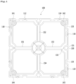
- the unit interior material attachment structure 100 having wall attachment part bolt grooves 141 to 144 includes: binding protrusions 110, 112, 114, 116 and 118 formed at the outermost part of the interior material attachment structure 100 in order to attach a metal interior material; and connection part grooves 130 formed adjacent to the binding protrusions 110 in order to connect the plurality of interior material attachment structures to each other.
- the interior material attachment structure 100 has the binding protrusions 110 formed on the left and right sides of the connection part groove 130.
- connection part grooves 130 are connected in a rib shape at the rear surfaces 132 of the connection part grooves 130.
- connection part grooves 130 When a connector 300 is connected through the connection part grooves 130 so as to bind the neighboring interior material attachment structures to the left and right sides of the connector 300, a predetermined force is required, and ribs 151 to 154 are constructed to reliably maintain the interior material attachment structure which is a plastic injection molded product.
- the plastic material is used for the interior material attachment structure.
- any materials may be used.
- the interior material attachment structure is formed in a rectangular shape, and the binding protrusions 110 are formed on the outer surface of the rectangular interior material attachment structure.
- Each of the binding protrusions is formed on one side of neighboring sides at a corner of the rectangular interior material attachment structure.
- the interior material attachment structure has a structure in which two binding protrusions are located on each side of the rectangular shape.
- the binding protrusion 118 is disposed close to a corner of the wall attachment part bolt groove 141 on one side of two sides abutting on the corner, and the binding protrusion 112 is disposed relatively remote from the corner on the other side of the two sides.
- the interior material attachment structure can be coupled to a metal interior material even though the interior material attachment structure is coupled in any directions, which makes it possible to maximize the efficiency of the work.
- the wall attachment part bolt grooves 141 to 144 are formed in the interior material attachment structure in order to attach the metal interior material to a wall.
- a binding retreat space 115 is formed at the rear surface of the binding protrusion 110.
- the interior material attachment structure may be reliably bound through the binding retreat space.
- the interior material attachment structure is manufactured in a square shape, and the unit interior material attachment structure is formed to have a size of 15cm.
- the interior material attachment structure may have various sizes.
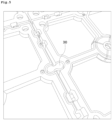
- FIG. 3 illustrates that four unit interior material attachment structures are manufactured at once when the unit interior material attachment structures are manufactured as plastic injection molded products. The bottoms of the unit interior material attachment structures are connected to each other when the unit interior material attachment structures are manufactured as thin plastic injection molded products.
- FIG. 4 will be described as follows.
- FIG. 4 illustrates an interior material attachment structure 200 obtained by connecting eight interior material attachment structures through the connector.
- the working time can be shortened, and the interior material attachment structure for the metal interior material may be attached to a desired wall surface.
- the interior material attachment structure is constructed in units of four unit interior material attachment structures. However, two, six, eight or more unit interior material attachment structures may be connected and injection-molded according to the necessity of working efficiency.
- the interior material attachment structure is formed to have the same size as the interior material during work.
- the work for an edge part, corner part or the like it takes a lot of time in the workplace, and it is difficult to neatly finish the interior material and the interior material attachment structure.
- the interior material attachment structure according to the present embodiment can be manufactured as small units, finish work for an edge or corner part is performed as easily as finish work for a wide part.
- the unit interior material attachment structure is formed to have a small size, the finish work can be ended within a short time, when a corner or edge part is finished. Therefore, it is possible to increase the efficiency of the work.
- Each of the binding protrusions 110, 112, 114, 116 and 118 has the binding retreat space 115 formed at the rear thereof, in order to secure a retreat space when the binding protrusion is coupled to an interior material 400.
- FIGS. 5 and 6 illustrate a connection method between adjacent interior material attachment structures.
- the connector for the interior material attachment structure has a binding step part 355, and is configured to secure a space such that the connector is reliably seated in a connection part hole 430 formed through a bent portion of a side surface of the metal interior material.
- the connector 300 is used.
- the connector 300 includes a first connection part 330, a connection part arm 350 having the binding step part 355, and a second connection part 340.
- the first connection part 330 is coupled to the connection part groove 130 of the interior material attachment structure.
- the second connection part 340 is bound to the connection part grooves 130 of the neighboring interior material attachment structures 100 so as to connect the unit interior material attachment structures.
- the binding step part 355 is passed through the connection part hole 430 formed in the metal interior material 400 when coupled to the interior material attachment structure 100.
- the connector 300 is bound to the connection part groove 130.
- a gap is formed, which is twice larger than the thickness of the interior material.
- the thickness of the metal interior material is 0.5mm. Since two metal interior materials are connected to the interior material attachment structure, a gap corresponding to a thickness of 1mm needs to be provided. In order to increase the efficiency of the work or to replace a defective metal interior material 400 or a defective interior material attachment structure 100, a working space needs to be provided. Therefore, the gap between the interior material attachment structures may be set to 2mm.
- Bind is applied to a connection part between the interior material attachment structure and the metal interior material.
- Connect is applied to a connection part between the unit interior material attachment structures.
- the unit interior material attachment structure 100 having wall attachment part bolt grooves 141 to 144 includes: binding protrusions 110, 112, 114, 116 and 118 formed at the outermost part of the interior material attachment structure 100 in order to attach a metal interior material; and connection part grooves 130 formed adjacent to the binding protrusions 110 in order to connect the plurality of interior material attachment structures to each other.
- the interior material attachment structure 100 has the binding protrusions 110 formed on the left and right sides of the connection part groove 130.
- connection part grooves 130 are connected in a rib shape at rear surfaces 132 of the connection part grooves 130.
- connection part grooves 130 When a connector 300 is connected through the connection part grooves 130 so as to bind the neighboring interior material attachment structures to the left and right sides of the connector 300, a predetermined force is required, and ribs 151 to 154 are constructed to reliably maintain the interior material attachment structure which is a plastic injection molded product.
- the plastic material is used for the interior material attachment structure.
- any materials may be used.
- the interior material attachment structure is formed in a rectangular shape, and the binding protrusions 110 are formed on the outer surface of the rectangular interior material attachment structure.
- Each of the binding protrusions is formed on one side of neighboring sides at a corner of the rectangular interior material attachment structure.
- the interior material attachment structure has a structure in which two binding protrusions are located on each side of the rectangular shape.
- the binding protrusion 118 is disposed close to a corner of the wall attachment part bolt groove 141 on one side of two sides abutting on the corner, and the binding protrusion 112 is disposed relatively remote from the corner on the other side of the two sides.
- the interior material attachment structure can be coupled to a metal interior material even though the interior material attachment structure is coupled in any directions, which makes it possible to maximize the efficiency of the work.
- the wall attachment part bolt grooves 141 to 144 are formed in the interior material attachment structure in order to attach the metal interior material to a wall.
- a binding retreat space 115 is formed at the rear surface of the binding protrusion 110.
- the interior material attachment structure may be reliably bound through the binding retreat space.
- the interior material attachment structure is manufactured in a square shape, and the unit interior material attachment structure is formed to have a size of 15cm.
- the interior material attachment structure may have various sizes.
- FIG. 3 illustrates that four unit interior material attachment structures are manufactured at a time when the unit interior material attachment structures are manufactured as plastic injection molded products.
- the bottoms of the unit interior material attachment structures are connected to each other when the unit interior material attachment structures are manufactured as thin plastic injection molded products.
- FIG. 4 will be described as follows.
- FIG. 4 illustrates an interior material attachment structure 200 obtained by connecting eight interior material attachment structures through the connector.
- the working time can be shortened, and the interior material attachment structure for the metal interior material may be attached to a desired wall surface.
- the interior material attachment structure is constructed in units of four unit interior material attachment structures. However, two, six, eight or more unit interior material attachment structures may be connected and injection-molded according to the necessity of the working efficiency.
- the interior material attachment structure is formed to have the same size as the interior material during work.
- the work for an edge part, a corner part or the like it takes a lot of time in the workplace, and it is difficult to neatly finish the interior material and the interior material attachment structure.
- the interior material attachment structure according to the present embodiment can be manufactured as small units, finish work for an edge part or a corner part is performed as easily as finish work for a wide part.
- the unit interior material attachment structure is formed to have a small unit size, the finish work can be ended within a short time, when a corner or edge part is finished. Therefore, it is possible to increase the efficiency of the work.
- Each of the binding protrusions 110, 112, 114, 116 and 118 has the binding retreat space 115 formed at the rear thereof, in order to secure a retreat space when the binding protrusion is coupled to an interior material 400.
- FIGS. 5 and 6 illustrate a connection method between adjacent interior material attachment structures.
- the connector for the interior material attachment structure has a binding step part 355, and is configured to secure a space such that the connector is reliably seated in a connection part hole 430 formed through a bent portion of a side surface of the metal interior material.
- the connector 300 is used.
- the connector 300 includes a first connection part 330, a connection part arm 350 having the binding step part 355, and a second connection part 340.
- the first connection part 330 is coupled to the connection part groove 130 of the interior material attachment structure.
- the second connection part 340 is bound to the connection part grooves 130 of the neighboring interior material attachment structures 100 so as to connect the unit interior material attachment structures.
- the binding step part 355 is passed through the connection part hole 430 formed in the metal interior material 400 when coupled to the interior material attachment structure 100.
- the connector 300 is bound to the connection part groove 130.
- a gap is formed, which is twice larger than the thickness of the interior material.
- the thickness of the metal interior material is 0.5mm. Since two metal interior materials are connected to the interior material attachment structure, a gap corresponding to a thickness of 1mm needs to be provided. In order to increase the efficiency of the work or to replace a defective metal interior material 400 or a defective interior material attachment structure 100, a working space needs to be provided. Therefore, the gap between the interior material attachment structures may be set to 2mm.
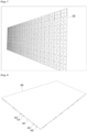
- FIG. 7 illustrates that the interior material attachment structure is attached to a wall surface to which the metal interior material is to be attached.
- FIG. 8 illustrates the metal interior material attached to the interior material attachment structure.
- a metal interior material 400 attached to a metal interior material attachment structure having wall attachment part bolt grooves 141 to 144 includes: binding protrusions 110, 112, 114, 116 and 118 formed at the outermost part of the interior material attachment structure 100 in order to attach the metal interior material; connection part grooves 130 formed adjacent to the binding protrusions in order to connect the plurality of metal interior material attachment structures to each other; binding protrusion holes 410, 420, 440 and 450 of the metal interior material, which are bound to the binding protrusions; and connection part holes 430 of the metal interior material, corresponding to a binding step part 355 of a connector inserted into the connection part groove.
- the binding protrusion holes 410, 420, 440 and 450 may be formed so that two binding protrusion holes are located on the left and right sides of the connection part hole 430, respectively.
- FIGS. 9, 10 and 11 will be described as follows.
- FIG. 9 illustrates a process of attaching the metal interior material.
- FIG. 10 illustrates that the metal interior material is completely attached.
- FIG. 11 illustrates that the interior material attachment structures are not successively arranged, but coupled to parts of the metal interior material.
- the binding protrusions of the metal interior material attachment structure are formed at a corner so as not to be symmetrical with each other, and the grooves of the metal interior material in FIG. 8 are formed with margins.
- the present disclosure provides a metal interior material serving as a flame retardant material or incombustible material.
- the interior material attachment structure is manufactured to install the metal interior material in a one-touch manner, thereby increasing the efficiency of the work.
- the construction process can be simplified to improve the market competitiveness of the metal interior material such as aluminum during a process of mass-producing metal interior material products.
- the unit interior material attachment structure is formed to have a small unit size, the finish work can be ended within a short time, when a corner or edge part is finished, which makes it possible to increase the economic feasibility of the work. Therefore, the present disclosure has industrial applicability.
Landscapes
- Engineering & Computer Science (AREA)
- Architecture (AREA)
- Civil Engineering (AREA)
- Structural Engineering (AREA)
- Physics & Mathematics (AREA)
- Electromagnetism (AREA)
- Finishing Walls (AREA)
- Joining Of Building Structures In Genera (AREA)
Claims (12)
- Zum Installieren an einer Innenwand oder Decke angepasste Innenmaterial-Befestigungsstruktur (100), auf der ein Metall-Innenmaterial aufgebracht ist, wobei die Innenmaterial-Befestigungsstruktur (100) umfasst:Wandbefestigungsteil-Schraubennuten (141, 142, 143, 144) zur Aufnahme einer Schraube zum Befestigen der Struktur an der Wand oder Decke;am äußeren Teil der Innenmaterial-Befestigungsstruktur (100) gebildete Klemmvorsprünge (110, 112, 114, 116, 118) zum Koppeln mit diesen und dadurch Befestigen des Metall-Innenmaterials an der Innenmaterial-Befestigungsstruktur; undangrenzend an die Klemmvorsprünge (110) gebildete Verbindungsteilnuten (130) zum Verbinden einer Vielzahl von solchen Innenmaterial-Befestigungsstrukturen miteinander;wobei die Klemmvorsprünge (110, 112, 114, 116, 118) einen an der gegenüberliegenden Seite der Klemmvorsprünge (110, 112, 114, 116, 118) gebildeten Klemmeinrückraum (115) aufweisen, um beim Koppeln mit dem Metall-Innenmaterial (400) einen Einrückraum (115) zu sichern; unddie Innenmaterial-Befestigungsstruktur (100) in einer rechteckigen Form gebildet ist und die Klemmvorsprünge (110, 112, 114, 116, 118) auf der äußeren Fläche der rechteckigen Innenmaterial-Befestigungsstruktur gebildet sind, um an benachbarten Seiten an einer Ecke der rechteckigen Innenmaterial-Befestigungsstruktur angeordnet zu sein.
- Innenmaterial-Befestigungsstruktur (100) nach Anspruch 1,
ferner umfassend einen an der Verbindungsteilnut (130) geklemmten Verbinder (300) zum Verbinden der Vielzahl von Innenmaterial-Befestigungsstrukturen (100). - Innenmaterial-Befestigungsstruktur (100) nach Anspruch 1,
wobei die Innenmaterial-Befestigungsstruktur (100) auf der linken und rechten Seite der Verbindungsteilnut (130) gebildete Klemmvorsprünge (110) aufweist. - Innenmaterial-Befestigungsstruktur (100) nach Anspruch 1,
wobei zum zuverlässigen Herstellen der Verbindungsteilnuten (130) die Verbindungsteilnuten (130) in einer Rippenform an Innenflächen von Öffnungen der Verbindungsteilnuten (130) verbunden sind. - Innenmaterial-Befestigungsstruktur (100) nach Anspruch 1,
wobei zwei Klemmvorsprünge (110, 112, 114, 116, 118) an jeder Seite der rechteckigen Form gebildet sind, wobei ein Klemmvorsprung (110, 114, 118) nahe einer Ecke an einer Seite von zwei an der Ecke anstoßenden Seiten angeordnet ist und der andere Klemmvorsprung (112, 116) relativ entfernt von der Ecke an der gleichen Seite angeordnet ist. - Vier-Einheiten-Innenmaterial-Befestigungsstruktur, umfassend vier gleichzeitig hergestellte Einheiten der Innenmaterial-Befestigungsstrukturen nach Anspruch 1.
- Vier-Einheiten-Innenmaterial-Befestigungsstruktur (100) nach Anspruch 6,
wobei zum Befestigen der Vier-Einheiten-Innenmaterial-Befestigungsstruktur (100) an einer Wandfläche die Vier-Einheiten-Innenmaterial-Befestigungsstruktur mit einer weiteren solchen Vier-Einheiten-Innenmaterial-Befestigungsstruktur angrenzend daran durch den Verbinder (300) verbunden wird. - Innenmaterial-Befestigungsstruktur (100) nach Anspruch 1,
wobei der Verbinder (300) ein Klemmabsatzteil (355) zum Bilden eines Einführraums des Metall-Innenmaterials (400) aufweist. - Innenmaterial-Befestigungsstruktur (100) nach Anspruch 2,
wobei der Verbinder (300) ein erstes Verbindungsteil (330), einen Verbindungsteilarm (350) mit dem Klemmabsatzteil (355) und ein zweites Verbindungsteil (340) umfasst, wobei das erste Verbindungsteil (330) mit der Verbindungsteilnut (130) der Innenmaterial-Befestigungsstruktur (100) gekoppelt ist, das zweite Verbindungsteil (340) an den Verbindungsteilnuten (130) der benachbarten Innenmaterial-Befestigungsstrukturen geklemmt ist, um die Einheiten-Innenmaterial-Befestigungsstrukturen zu verbinden, und das Klemmabsatzteil (355) beim Koppeln mit der Innenmaterial-Befestigungsstruktur (100) durch ein im Metall-Innenmaterial (400) gebildetes Verbindungsteilloch (430) geführt wird. - Vier-Einheiten-Innenmaterial-Befestigungsstruktur (100) nach Anspruch 6,
wobei ein Abstand zwischen der Vier-Einheiten-Innenmaterial-Befestigungsstruktur und einer weiteren solchen Vier-Einheiten-Innenmaterial-Befestigungsstruktur angrenzend daran größer ist als die Stärke des Metall-Innenmaterials (400). - Kombination eines an einer Innenmaterial-Befestigungsstruktur (100) nach Anspruch 1 befestigten Metall-Innenmaterials (400) durch Klemmen der Klemmvorsprünge (110, 112, 114, 116, 118) in im Metall-Innenmaterial gebildeten Klemmvorsprungslöchern (410, 420, 440, 450), wobei das Metall-Innenmaterial ein Verbindungsteilloch (430) des Metall-Innenmaterials (400) umfasst, entsprechend einem Klemmabsatzteil (355) eines in die Verbindungsteilnut (130) der Innenmaterial-Befestigungsstruktur (100) eingeführten Verbinders (300).
- Kombination nach Anspruch 11,
wobei zwei Klemmvorsprungslöcher jeweils an der linken und rechten Seite des Verbindungsteillochs (430) gebildet sind.
Applications Claiming Priority (2)
| Application Number | Priority Date | Filing Date | Title |
|---|---|---|---|
| KR1020180021336A KR102074769B1 (ko) | 2018-02-22 | 2018-02-22 | 금속 내장재 및 내장재 부착 구조물 |
| PCT/KR2019/002128 WO2019164295A1 (ko) | 2018-02-22 | 2019-02-21 | 금속 내장재 및 내장재 부착 구조물 |
Publications (3)
| Publication Number | Publication Date |
|---|---|
| EP3757312A1 EP3757312A1 (de) | 2020-12-30 |
| EP3757312A4 EP3757312A4 (de) | 2021-11-24 |
| EP3757312B1 true EP3757312B1 (de) | 2023-06-07 |
Family
ID=67688266
Family Applications (1)
| Application Number | Title | Priority Date | Filing Date |
|---|---|---|---|
| EP19756746.4A Active EP3757312B1 (de) | 2018-02-22 | 2019-02-21 | Innenmaterial aus metall und befestigungsstruktur des innenmaterials |
Country Status (8)
| Country | Link |
|---|---|
| US (1) | US11319711B2 (de) |
| EP (1) | EP3757312B1 (de) |
| JP (1) | JP7037217B2 (de) |
| KR (1) | KR102074769B1 (de) |
| CN (1) | CN111771036A (de) |
| DK (1) | DK3757312T3 (de) |
| FI (1) | FI3757312T3 (de) |
| WO (1) | WO2019164295A1 (de) |
Families Citing this family (5)
| Publication number | Priority date | Publication date | Assignee | Title |
|---|---|---|---|---|
| US20230105519A1 (en) * | 2020-05-27 | 2023-04-06 | Ig Kogyo Co., Ltd. | Decorative structure, panel material, and method for constructing decorative structure |
| KR102317642B1 (ko) | 2020-12-22 | 2021-10-26 | 삼원액트 주식회사 | 단위 브라켓, 브라켓 |
| JP6906829B1 (ja) | 2021-02-12 | 2021-07-21 | タケシンパッケージ株式会社 | 意匠材セット及び意匠材セットの設置方法 |
| KR102791346B1 (ko) * | 2023-02-06 | 2025-04-08 | 삼원액트 주식회사 | 내장재 부착구조물 |
| KR102936068B1 (ko) | 2024-04-03 | 2026-03-09 | 삼원액트 주식회사 | 후크부 및 이를 부착한 내장재부착구조물 |
Family Cites Families (59)
| Publication number | Priority date | Publication date | Assignee | Title |
|---|---|---|---|---|
| US5323575A (en) * | 1993-06-01 | 1994-06-28 | Yeh Tzung Jzng | Tile and mounting mat assembly |
| US5616389A (en) * | 1995-10-30 | 1997-04-01 | Blatz; Warren J. | Surface covering tile |
| KR19980057306A (ko) | 1996-12-30 | 1998-09-25 | 박병재 | 자동차의 내장재 구조 |
| AUPP137798A0 (en) * | 1998-01-16 | 1998-02-05 | Ezydeck Pty Ltd | Decking tile |
| US20030061772A1 (en) * | 1998-01-16 | 2003-04-03 | Bertolini Geoffrey Michael | Decking tile |
| AU134587S (en) * | 1998-01-16 | 1998-08-04 | Ezydeck Pty Ltd | Decking tile |
| US6751916B1 (en) * | 1999-06-24 | 2004-06-22 | Sandy A. Ritzer | Decorative structure with slotted grid and detachably secured tiles |
| FR2823781B1 (fr) * | 2001-04-19 | 2003-12-12 | Zhi Wen Tseng | Structure de plancher en bois |
| CN2496960Y (zh) * | 2001-08-24 | 2002-06-26 | 谢达嘉 | 塑料地垫 |
| US6694691B2 (en) * | 2002-01-22 | 2004-02-24 | Chen Chung Ku | Combination floor pad having composite base boards |
| CN2526390Y (zh) * | 2002-03-01 | 2002-12-18 | 李江 | 一种可拆卸的冷库用塑胶地板 |
| KR200287104Y1 (ko) * | 2002-06-10 | 2002-08-27 | 강혜영 | 건축재용 조립식 판넬 |
| USD522149S1 (en) * | 2003-06-23 | 2006-05-30 | Jeong Gil Shin | Tile base |
| WO2006042883A2 (es) * | 2004-08-20 | 2006-04-27 | Azulindus Y Marti, S.A. | Revestimiento desmontable para superficies |
| KR200368965Y1 (ko) | 2004-08-23 | 2004-12-03 | 김성일 | 핫멜트 시트가 부착된 천연 무늬목 내장재 |
| MX2007007608A (es) * | 2004-12-23 | 2007-08-03 | Bernard Mcnamara | Pared de encofrado modular con conectores de junta de cola de milano. |
| US20060185297A1 (en) * | 2005-02-18 | 2006-08-24 | Tzu-Chiang Mei | Combination structure of a quick assembly do-it-yourself (DIY) wood flooring |
| KR100575093B1 (ko) | 2005-03-22 | 2006-04-28 | 주식회사 한국화이바 | 철도차량의 내장재에 광고판 매립부를 형성하는 방법 및광고판 매립부 구조 |
| US7487622B2 (en) * | 2005-05-17 | 2009-02-10 | Wang Dennis H | Interlocking frame system for floor and wall structures |
| GB2426527A (en) * | 2005-05-26 | 2006-11-29 | Rhr Solutions Ltd | A tile and tiling apparatus |
| JP2007239311A (ja) * | 2006-03-09 | 2007-09-20 | Ig Tech Res Inc | 化粧壁材の施工方法 |
| ES1062734Y (es) * | 2006-04-17 | 2006-10-16 | Golden Decking S L | Placa perfeccionada para la configuracion de suelos |
| USD553264S1 (en) * | 2006-07-10 | 2007-10-16 | Shin Jeong-Gil | Tile base |
| CA2669203A1 (en) * | 2006-11-20 | 2008-05-29 | Gruppo Concorde S.P.A. | A system and a method of dry laying of covering elements for floors or walls and a support for said system |
| WO2008083414A2 (en) * | 2007-01-03 | 2008-07-10 | Russell Colin Peinke | Tiles and mosaics |
| CN101270607A (zh) * | 2007-04-05 | 2008-09-24 | 赖英光 | 具有架高底座的塑料地板组合 |
| KR20090003704U (ko) * | 2007-04-05 | 2009-04-21 | 잉-쿠앙 레이 | 조립식 매트 |
| US9010060B2 (en) * | 2007-05-09 | 2015-04-21 | Antonio Rapaz | Construction panel |
| US20080276557A1 (en) * | 2007-05-09 | 2008-11-13 | Antonio Rapaz | Construction panel |
| US8464490B2 (en) * | 2007-05-09 | 2013-06-18 | Antonio Rapaz | Construction panel |
| CN100453756C (zh) * | 2007-06-06 | 2009-01-21 | 张吉华 | 大型单元装配式夹芯装饰板 |
| KR20090003704A (ko) | 2007-07-03 | 2009-01-12 | 정연태 | 지하매설 물탱크 장치 |
| KR100894014B1 (ko) * | 2007-08-28 | 2009-04-17 | 이병학 | 조립식 내장패널 |
| MX2010004741A (es) * | 2007-10-30 | 2010-09-28 | Unika Australia Pty Ltd | Charola para loseta. |
| KR100900508B1 (ko) * | 2008-02-27 | 2009-06-03 | 김세영 | 벽체배수판 |
| US20090266022A1 (en) * | 2008-04-28 | 2009-10-29 | Ling Chen Lin | Indoor/outdoor interlocking deck tile device |
| KR100889380B1 (ko) * | 2008-05-29 | 2009-03-19 | 주식회사 대진디에스피 | 금속 모자이크 타일 |
| CN101440659A (zh) * | 2008-10-31 | 2009-05-27 | 赖英光 | 一种新型塑料地垫 |
| US7827742B2 (en) * | 2009-01-08 | 2010-11-09 | Vicente Francisco Sansano Marti | Removable covering for surfaces |
| US8205407B2 (en) * | 2009-04-15 | 2012-06-26 | Genova Michael C | Modular decking system |
| US8266849B2 (en) * | 2009-05-27 | 2012-09-18 | Mcfarland Cascade Holdings, Inc. | Interlocking platform panels and modules |
| US20110023389A1 (en) * | 2009-07-01 | 2011-02-03 | Universal Exports, LLC | Modular deck tile |
| KR20110019913A (ko) * | 2009-08-21 | 2011-03-02 | 주식회사 대창산업 | 다양한 디자인을 표현할 수 있는 벽체용 방습패널과 이를 위한 베이스프레임 |
| US8539727B2 (en) * | 2009-11-19 | 2013-09-24 | Sun Wah Lui | Mechanically-held tile |
| EP2525881A4 (de) * | 2010-01-22 | 2015-09-09 | Connor Sport Court International Inc | Modulares unterbodensystem |
| US8881482B2 (en) * | 2010-01-22 | 2014-11-11 | Connor Sport Court International, Llc | Modular flooring system |
| FR2964683B1 (fr) * | 2010-09-09 | 2013-07-19 | Grosfillex Sas | Structure de revetement |
| GB2495790B (en) * | 2012-02-07 | 2014-07-16 | Ryan Patrick Hurson | A floor tile |
| FR2988412B1 (fr) * | 2012-03-22 | 2016-02-26 | F G I Sas | Ensemble modulaire perfectionne pour la realisation d'un revetement de sol |
| FR2989982A1 (fr) * | 2012-04-27 | 2013-11-01 | Bacacier 3 S | Dispositif de revetement d'une structure de batiment et structure revetue par un tel dispositif |
| TW201504505A (zh) * | 2013-07-25 | 2015-02-01 | Nexus Global Co Ltd | 戶外拼接地板 |
| CN103572918B (zh) * | 2013-10-15 | 2015-10-28 | 路成岗 | 一种立体三维保温装饰扣板 |
| US20150252563A1 (en) * | 2014-03-04 | 2015-09-10 | Conner Sport Court International, LLC | Synthetic flooring apparatus |
| EP3231957A1 (de) * | 2016-04-14 | 2017-10-18 | B&R Solutions B.V. | Trägerkachel für gekachelte terrasse |
| CA3030481A1 (en) * | 2016-07-29 | 2018-02-01 | Quality Mat Company | Lightweight universal panel mat |
| IT201600107627A1 (it) * | 2016-10-25 | 2018-04-25 | Dakota Group S A S Di Zeno Cipriani & C | Sistema di supporto per pavimentazioni sopraelevate e pavimentazione ottenuta con tale sistema di supporto |
| CN106760381A (zh) * | 2016-12-14 | 2017-05-31 | 浙江亚厦装饰股份有限公司 | 一种自由插接地面的铺装复合板 |
| US10827865B2 (en) * | 2017-10-24 | 2020-11-10 | Milliken & Company | Modular floor mat |
| US20190127991A1 (en) * | 2017-11-01 | 2019-05-02 | Luis Santana | Grid Plate for Laying Tile on Uneven Surfaces |
-
2018
- 2018-02-22 KR KR1020180021336A patent/KR102074769B1/ko active Active
-
2019
- 2019-02-21 US US16/971,134 patent/US11319711B2/en active Active
- 2019-02-21 DK DK19756746.4T patent/DK3757312T3/da active
- 2019-02-21 CN CN201980014423.XA patent/CN111771036A/zh active Pending
- 2019-02-21 EP EP19756746.4A patent/EP3757312B1/de active Active
- 2019-02-21 FI FIEP19756746.4T patent/FI3757312T3/fi active
- 2019-02-21 JP JP2020544539A patent/JP7037217B2/ja active Active
- 2019-02-21 WO PCT/KR2019/002128 patent/WO2019164295A1/ko not_active Ceased
Also Published As
| Publication number | Publication date |
|---|---|
| DK3757312T3 (da) | 2023-09-18 |
| JP2021515124A (ja) | 2021-06-17 |
| FI3757312T3 (fi) | 2023-09-08 |
| EP3757312A1 (de) | 2020-12-30 |
| KR102074769B1 (ko) | 2020-02-07 |
| JP7037217B2 (ja) | 2022-03-16 |
| CN111771036A (zh) | 2020-10-13 |
| US20210102381A1 (en) | 2021-04-08 |
| EP3757312A4 (de) | 2021-11-24 |
| US11319711B2 (en) | 2022-05-03 |
| KR20190101242A (ko) | 2019-08-30 |
| WO2019164295A1 (ko) | 2019-08-29 |
Similar Documents
| Publication | Publication Date | Title |
|---|---|---|
| EP3757312B1 (de) | Innenmaterial aus metall und befestigungsstruktur des innenmaterials | |
| CA2745447C (en) | Tile systems and methods of making and using same | |
| CN205577169U (zh) | 一种整体模块化装配式成品隔断墙 | |
| US12006698B2 (en) | Metal material to which flammable thin-film construction interior material is adhered, and attachment structure for attaching same | |
| CN113356501A (zh) | 装饰板的离缝安装组件、装饰板的离缝结构及其装配方法 | |
| CN214462185U (zh) | 一种便捷型吊顶造型结构 | |
| CN213927061U (zh) | 一种可快速安装的装配式内墙板 | |
| CN216516628U (zh) | 一种龙骨转接板 | |
| CN113431287B (zh) | 装饰板的收边安装组件、装饰板收边结构及其安装方法 | |
| CN214364555U (zh) | 一种墙板连接结构 | |
| CN211973903U (zh) | 一种绿色建筑施工用防噪声装置 | |
| CN210645137U (zh) | 一种用于积木连接的卡扣固定装置 | |
| KR101389185B1 (ko) | 건축물용 불연성 패널 | |
| CN202265977U (zh) | 一种木塑板的公母槽固定连接件 | |
| CN203347172U (zh) | 一种塑木桑拿板塑料网格托底 | |
| CN215564069U (zh) | 一种装饰板的独立插接安装组件及装饰板的独立插接结构 | |
| WO2006133704A1 (en) | Process for creating an angle connection in a plane member | |
| CN214943677U (zh) | 组装式门结构 | |
| CN221031113U (zh) | 一种环保型柔石墙板 | |
| CN216007520U (zh) | 一种便于拼装的复合板 | |
| CN215564089U (zh) | 用于装配式墙板安装的鱼骨式卡件 | |
| CN215948756U (zh) | 一种便于拼装的板材 | |
| CN114475077B (zh) | 一种弧形装饰板的装配式加工方法及弧形装饰板结构 | |
| CN211774719U (zh) | 一种内墙隔音板 | |
| CN213268902U (zh) | 一种建筑用组合式建筑拼接模板 |
Legal Events
| Date | Code | Title | Description |
|---|---|---|---|
| STAA | Information on the status of an ep patent application or granted ep patent |
Free format text: STATUS: THE INTERNATIONAL PUBLICATION HAS BEEN MADE |
|
| PUAI | Public reference made under article 153(3) epc to a published international application that has entered the european phase |
Free format text: ORIGINAL CODE: 0009012 |
|
| STAA | Information on the status of an ep patent application or granted ep patent |
Free format text: STATUS: REQUEST FOR EXAMINATION WAS MADE |
|
| 17P | Request for examination filed |
Effective date: 20200825 |
|
| AK | Designated contracting states |
Kind code of ref document: A1 Designated state(s): AL AT BE BG CH CY CZ DE DK EE ES FI FR GB GR HR HU IE IS IT LI LT LU LV MC MK MT NL NO PL PT RO RS SE SI SK SM TR |
|
| AX | Request for extension of the european patent |
Extension state: BA ME |
|
| DAV | Request for validation of the european patent (deleted) | ||
| DAX | Request for extension of the european patent (deleted) | ||
| A4 | Supplementary search report drawn up and despatched |
Effective date: 20211026 |
|
| RIC1 | Information provided on ipc code assigned before grant |
Ipc: E04B 9/04 20060101ALI20211020BHEP Ipc: E04F 13/08 20060101ALI20211020BHEP Ipc: E04F 13/12 20060101ALI20211020BHEP Ipc: E04F 15/06 20060101ALI20211020BHEP Ipc: E04F 15/02 20060101AFI20211020BHEP |
|
| STAA | Information on the status of an ep patent application or granted ep patent |
Free format text: STATUS: EXAMINATION IS IN PROGRESS |
|
| 17Q | First examination report despatched |
Effective date: 20220131 |
|
| GRAP | Despatch of communication of intention to grant a patent |
Free format text: ORIGINAL CODE: EPIDOSNIGR1 |
|
| STAA | Information on the status of an ep patent application or granted ep patent |
Free format text: STATUS: GRANT OF PATENT IS INTENDED |
|
| INTG | Intention to grant announced |
Effective date: 20221102 |
|
| GRAS | Grant fee paid |
Free format text: ORIGINAL CODE: EPIDOSNIGR3 |
|
| RIN1 | Information on inventor provided before grant (corrected) |
Inventor name: HAN, HONG SUK Inventor name: LEE, KYUNG YUL Inventor name: LEE, KYUNG WOOK |
|
| GRAA | (expected) grant |
Free format text: ORIGINAL CODE: 0009210 |
|
| STAA | Information on the status of an ep patent application or granted ep patent |
Free format text: STATUS: THE PATENT HAS BEEN GRANTED |
|
| AK | Designated contracting states |
Kind code of ref document: B1 Designated state(s): AL AT BE BG CH CY CZ DE DK EE ES FI FR GB GR HR HU IE IS IT LI LT LU LV MC MK MT NL NO PL PT RO RS SE SI SK SM TR |
|
| REG | Reference to a national code |
Ref country code: GB Ref legal event code: FG4D |
|
| REG | Reference to a national code |
Ref country code: CH Ref legal event code: EP Ref country code: AT Ref legal event code: REF Ref document number: 1575491 Country of ref document: AT Kind code of ref document: T Effective date: 20230615 |
|
| REG | Reference to a national code |
Ref country code: DE Ref legal event code: R096 Ref document number: 602019030355 Country of ref document: DE |
|
| REG | Reference to a national code |
Ref country code: FI Ref legal event code: FGE |
|
| REG | Reference to a national code |
Ref country code: DK Ref legal event code: T3 Effective date: 20230912 |
|
| REG | Reference to a national code |
Ref country code: LT Ref legal event code: MG9D |
|
| REG | Reference to a national code |
Ref country code: SE Ref legal event code: TRGR |
|
| REG | Reference to a national code |
Ref country code: NL Ref legal event code: MP Effective date: 20230607 |
|
| REG | Reference to a national code |
Ref country code: NO Ref legal event code: T2 Effective date: 20230607 |
|
| PG25 | Lapsed in a contracting state [announced via postgrant information from national office to epo] |
Ref country code: ES Free format text: LAPSE BECAUSE OF FAILURE TO SUBMIT A TRANSLATION OF THE DESCRIPTION OR TO PAY THE FEE WITHIN THE PRESCRIBED TIME-LIMIT Effective date: 20230607 |
|
| REG | Reference to a national code |
Ref country code: AT Ref legal event code: MK05 Ref document number: 1575491 Country of ref document: AT Kind code of ref document: T Effective date: 20230607 |
|
| PG25 | Lapsed in a contracting state [announced via postgrant information from national office to epo] |
Ref country code: RS Free format text: LAPSE BECAUSE OF FAILURE TO SUBMIT A TRANSLATION OF THE DESCRIPTION OR TO PAY THE FEE WITHIN THE PRESCRIBED TIME-LIMIT Effective date: 20230607 Ref country code: NL Free format text: LAPSE BECAUSE OF FAILURE TO SUBMIT A TRANSLATION OF THE DESCRIPTION OR TO PAY THE FEE WITHIN THE PRESCRIBED TIME-LIMIT Effective date: 20230607 Ref country code: LV Free format text: LAPSE BECAUSE OF FAILURE TO SUBMIT A TRANSLATION OF THE DESCRIPTION OR TO PAY THE FEE WITHIN THE PRESCRIBED TIME-LIMIT Effective date: 20230607 Ref country code: LT Free format text: LAPSE BECAUSE OF FAILURE TO SUBMIT A TRANSLATION OF THE DESCRIPTION OR TO PAY THE FEE WITHIN THE PRESCRIBED TIME-LIMIT Effective date: 20230607 Ref country code: HR Free format text: LAPSE BECAUSE OF FAILURE TO SUBMIT A TRANSLATION OF THE DESCRIPTION OR TO PAY THE FEE WITHIN THE PRESCRIBED TIME-LIMIT Effective date: 20230607 Ref country code: GR Free format text: LAPSE BECAUSE OF FAILURE TO SUBMIT A TRANSLATION OF THE DESCRIPTION OR TO PAY THE FEE WITHIN THE PRESCRIBED TIME-LIMIT Effective date: 20230908 |
|
| PG25 | Lapsed in a contracting state [announced via postgrant information from national office to epo] |
Ref country code: SK Free format text: LAPSE BECAUSE OF FAILURE TO SUBMIT A TRANSLATION OF THE DESCRIPTION OR TO PAY THE FEE WITHIN THE PRESCRIBED TIME-LIMIT Effective date: 20230607 |
|
| PG25 | Lapsed in a contracting state [announced via postgrant information from national office to epo] |
Ref country code: IS Free format text: LAPSE BECAUSE OF FAILURE TO SUBMIT A TRANSLATION OF THE DESCRIPTION OR TO PAY THE FEE WITHIN THE PRESCRIBED TIME-LIMIT Effective date: 20231007 |
|
| PG25 | Lapsed in a contracting state [announced via postgrant information from national office to epo] |
Ref country code: SM Free format text: LAPSE BECAUSE OF FAILURE TO SUBMIT A TRANSLATION OF THE DESCRIPTION OR TO PAY THE FEE WITHIN THE PRESCRIBED TIME-LIMIT Effective date: 20230607 Ref country code: SK Free format text: LAPSE BECAUSE OF FAILURE TO SUBMIT A TRANSLATION OF THE DESCRIPTION OR TO PAY THE FEE WITHIN THE PRESCRIBED TIME-LIMIT Effective date: 20230607 Ref country code: RO Free format text: LAPSE BECAUSE OF FAILURE TO SUBMIT A TRANSLATION OF THE DESCRIPTION OR TO PAY THE FEE WITHIN THE PRESCRIBED TIME-LIMIT Effective date: 20230607 Ref country code: PT Free format text: LAPSE BECAUSE OF FAILURE TO SUBMIT A TRANSLATION OF THE DESCRIPTION OR TO PAY THE FEE WITHIN THE PRESCRIBED TIME-LIMIT Effective date: 20231009 Ref country code: IS Free format text: LAPSE BECAUSE OF FAILURE TO SUBMIT A TRANSLATION OF THE DESCRIPTION OR TO PAY THE FEE WITHIN THE PRESCRIBED TIME-LIMIT Effective date: 20231007 Ref country code: EE Free format text: LAPSE BECAUSE OF FAILURE TO SUBMIT A TRANSLATION OF THE DESCRIPTION OR TO PAY THE FEE WITHIN THE PRESCRIBED TIME-LIMIT Effective date: 20230607 Ref country code: CZ Free format text: LAPSE BECAUSE OF FAILURE TO SUBMIT A TRANSLATION OF THE DESCRIPTION OR TO PAY THE FEE WITHIN THE PRESCRIBED TIME-LIMIT Effective date: 20230607 Ref country code: AT Free format text: LAPSE BECAUSE OF FAILURE TO SUBMIT A TRANSLATION OF THE DESCRIPTION OR TO PAY THE FEE WITHIN THE PRESCRIBED TIME-LIMIT Effective date: 20230607 |
|
| PG25 | Lapsed in a contracting state [announced via postgrant information from national office to epo] |
Ref country code: PL Free format text: LAPSE BECAUSE OF FAILURE TO SUBMIT A TRANSLATION OF THE DESCRIPTION OR TO PAY THE FEE WITHIN THE PRESCRIBED TIME-LIMIT Effective date: 20230607 |
|
| REG | Reference to a national code |
Ref country code: DE Ref legal event code: R097 Ref document number: 602019030355 Country of ref document: DE |
|
| PLBE | No opposition filed within time limit |
Free format text: ORIGINAL CODE: 0009261 |
|
| STAA | Information on the status of an ep patent application or granted ep patent |
Free format text: STATUS: NO OPPOSITION FILED WITHIN TIME LIMIT |
|
| PG25 | Lapsed in a contracting state [announced via postgrant information from national office to epo] |
Ref country code: SI Free format text: LAPSE BECAUSE OF FAILURE TO SUBMIT A TRANSLATION OF THE DESCRIPTION OR TO PAY THE FEE WITHIN THE PRESCRIBED TIME-LIMIT Effective date: 20230607 |
|
| 26N | No opposition filed |
Effective date: 20240308 |
|
| PG25 | Lapsed in a contracting state [announced via postgrant information from national office to epo] |
Ref country code: SI Free format text: LAPSE BECAUSE OF FAILURE TO SUBMIT A TRANSLATION OF THE DESCRIPTION OR TO PAY THE FEE WITHIN THE PRESCRIBED TIME-LIMIT Effective date: 20230607 Ref country code: IT Free format text: LAPSE BECAUSE OF FAILURE TO SUBMIT A TRANSLATION OF THE DESCRIPTION OR TO PAY THE FEE WITHIN THE PRESCRIBED TIME-LIMIT Effective date: 20230607 |
|
| PG25 | Lapsed in a contracting state [announced via postgrant information from national office to epo] |
Ref country code: BG Free format text: LAPSE BECAUSE OF FAILURE TO SUBMIT A TRANSLATION OF THE DESCRIPTION OR TO PAY THE FEE WITHIN THE PRESCRIBED TIME-LIMIT Effective date: 20230607 |
|
| PG25 | Lapsed in a contracting state [announced via postgrant information from national office to epo] |
Ref country code: BG Free format text: LAPSE BECAUSE OF FAILURE TO SUBMIT A TRANSLATION OF THE DESCRIPTION OR TO PAY THE FEE WITHIN THE PRESCRIBED TIME-LIMIT Effective date: 20230607 |
|
| PGFP | Annual fee paid to national office [announced via postgrant information from national office to epo] |
Ref country code: LU Payment date: 20250225 Year of fee payment: 7 |
|
| PGFP | Annual fee paid to national office [announced via postgrant information from national office to epo] |
Ref country code: MC Payment date: 20250225 Year of fee payment: 7 |
|
| PGFP | Annual fee paid to national office [announced via postgrant information from national office to epo] |
Ref country code: DE Payment date: 20250227 Year of fee payment: 7 |
|
| PGFP | Annual fee paid to national office [announced via postgrant information from national office to epo] |
Ref country code: DK Payment date: 20250225 Year of fee payment: 7 Ref country code: FI Payment date: 20250225 Year of fee payment: 7 |
|
| PGFP | Annual fee paid to national office [announced via postgrant information from national office to epo] |
Ref country code: IE Payment date: 20250225 Year of fee payment: 7 Ref country code: SE Payment date: 20250225 Year of fee payment: 7 |
|
| PGFP | Annual fee paid to national office [announced via postgrant information from national office to epo] |
Ref country code: NO Payment date: 20250211 Year of fee payment: 7 |
|
| PGFP | Annual fee paid to national office [announced via postgrant information from national office to epo] |
Ref country code: BE Payment date: 20250226 Year of fee payment: 7 Ref country code: CH Payment date: 20250301 Year of fee payment: 7 |
|
| PG25 | Lapsed in a contracting state [announced via postgrant information from national office to epo] |
Ref country code: CY Free format text: LAPSE BECAUSE OF FAILURE TO SUBMIT A TRANSLATION OF THE DESCRIPTION OR TO PAY THE FEE WITHIN THE PRESCRIBED TIME-LIMIT; INVALID AB INITIO Effective date: 20190221 |
|
| PG25 | Lapsed in a contracting state [announced via postgrant information from national office to epo] |
Ref country code: HU Free format text: LAPSE BECAUSE OF FAILURE TO SUBMIT A TRANSLATION OF THE DESCRIPTION OR TO PAY THE FEE WITHIN THE PRESCRIBED TIME-LIMIT; INVALID AB INITIO Effective date: 20190221 |
|
| PG25 | Lapsed in a contracting state [announced via postgrant information from national office to epo] |
Ref country code: TR Free format text: LAPSE BECAUSE OF FAILURE TO SUBMIT A TRANSLATION OF THE DESCRIPTION OR TO PAY THE FEE WITHIN THE PRESCRIBED TIME-LIMIT Effective date: 20230607 |
|
| REG | Reference to a national code |
Ref country code: CH Ref legal event code: U11 Free format text: ST27 STATUS EVENT CODE: U-0-0-U10-U11 (AS PROVIDED BY THE NATIONAL OFFICE) Effective date: 20260402 |
|
| PGFP | Annual fee paid to national office [announced via postgrant information from national office to epo] |
Ref country code: GB Payment date: 20260327 Year of fee payment: 8 |
|
| PGFP | Annual fee paid to national office [announced via postgrant information from national office to epo] |
Ref country code: FR Payment date: 20260330 Year of fee payment: 8 |