EP3755908B1 - Dispositif de retenue pour organe filete, notamment pour ecrou - Google Patents
Dispositif de retenue pour organe filete, notamment pour ecrou Download PDFInfo
- Publication number
- EP3755908B1 EP3755908B1 EP19708401.5A EP19708401A EP3755908B1 EP 3755908 B1 EP3755908 B1 EP 3755908B1 EP 19708401 A EP19708401 A EP 19708401A EP 3755908 B1 EP3755908 B1 EP 3755908B1
- Authority
- EP
- European Patent Office
- Prior art keywords
- retaining device
- intermediate element
- threaded member
- retaining
- coupling
- Prior art date
- Legal status (The legal status is an assumption and is not a legal conclusion. Google has not performed a legal analysis and makes no representation as to the accuracy of the status listed.)
- Active
Links
Images

Classifications
-
- F—MECHANICAL ENGINEERING; LIGHTING; HEATING; WEAPONS; BLASTING
- F16—ENGINEERING ELEMENTS AND UNITS; GENERAL MEASURES FOR PRODUCING AND MAINTAINING EFFECTIVE FUNCTIONING OF MACHINES OR INSTALLATIONS; THERMAL INSULATION IN GENERAL
- F16B—DEVICES FOR FASTENING OR SECURING CONSTRUCTIONAL ELEMENTS OR MACHINE PARTS TOGETHER, e.g. NAILS, BOLTS, CIRCLIPS, CLAMPS, CLIPS OR WEDGES; JOINTS OR JOINTING
- F16B39/00—Locking of screws, bolts or nuts
- F16B39/02—Locking of screws, bolts or nuts in which the locking takes place after screwing down
- F16B39/10—Locking of screws, bolts or nuts in which the locking takes place after screwing down by a plate, spring, wire or ring immovable with regard to the bolt or object and mainly perpendicular to the axis of the bolt
-
- F—MECHANICAL ENGINEERING; LIGHTING; HEATING; WEAPONS; BLASTING
- F16—ENGINEERING ELEMENTS AND UNITS; GENERAL MEASURES FOR PRODUCING AND MAINTAINING EFFECTIVE FUNCTIONING OF MACHINES OR INSTALLATIONS; THERMAL INSULATION IN GENERAL
- F16B—DEVICES FOR FASTENING OR SECURING CONSTRUCTIONAL ELEMENTS OR MACHINE PARTS TOGETHER, e.g. NAILS, BOLTS, CIRCLIPS, CLAMPS, CLIPS OR WEDGES; JOINTS OR JOINTING
- F16B37/00—Nuts or like thread-engaging members
- F16B37/04—Devices for fastening nuts to surfaces, e.g. sheets, plates
- F16B37/044—Nut cages
-
- F—MECHANICAL ENGINEERING; LIGHTING; HEATING; WEAPONS; BLASTING
- F16—ENGINEERING ELEMENTS AND UNITS; GENERAL MEASURES FOR PRODUCING AND MAINTAINING EFFECTIVE FUNCTIONING OF MACHINES OR INSTALLATIONS; THERMAL INSULATION IN GENERAL
- F16B—DEVICES FOR FASTENING OR SECURING CONSTRUCTIONAL ELEMENTS OR MACHINE PARTS TOGETHER, e.g. NAILS, BOLTS, CIRCLIPS, CLAMPS, CLIPS OR WEDGES; JOINTS OR JOINTING
- F16B37/00—Nuts or like thread-engaging members
- F16B37/04—Devices for fastening nuts to surfaces, e.g. sheets, plates
-
- F—MECHANICAL ENGINEERING; LIGHTING; HEATING; WEAPONS; BLASTING
- F16—ENGINEERING ELEMENTS AND UNITS; GENERAL MEASURES FOR PRODUCING AND MAINTAINING EFFECTIVE FUNCTIONING OF MACHINES OR INSTALLATIONS; THERMAL INSULATION IN GENERAL
- F16B—DEVICES FOR FASTENING OR SECURING CONSTRUCTIONAL ELEMENTS OR MACHINE PARTS TOGETHER, e.g. NAILS, BOLTS, CIRCLIPS, CLAMPS, CLIPS OR WEDGES; JOINTS OR JOINTING
- F16B39/00—Locking of screws, bolts or nuts
- F16B39/02—Locking of screws, bolts or nuts in which the locking takes place after screwing down
- F16B39/08—Locking of screws, bolts or nuts in which the locking takes place after screwing down with a cap interacting with the nut, connected to the bolt by a pin or cotter pin
Definitions
- the present invention relates to a retaining device for a threaded member, in particular for a nut.
- fixings In certain applications, particularly in aeronautical applications and even more particularly in aircraft engines, fixings must be made by screwing while one of the threaded members, typically a nut, is very difficult to access to prevent it from turning during the screwing or unscrewing rotation of the other threaded member, for example a screw.
- Nuts which can be pre-fixed in a suitable position for subsequent screwing. But these nuts are often special, non-standard nuts. There is another problem with such nuts: when two parts have to be fixed by several screws, such nuts fixedly positioned on one of the parts prevent any adjustment of dimensional tolerances of this part in relation to the other. Also known are so-called "floating cage nuts”, offered for example by Raceparts (UK) Ltd, Unit 3, Rockfort Ind Est, Hithercroft Rd, Wallingford, UK, specially shaped to couple with radial clearance to a body - or cage - which is pre-fixed to one of the parts. Such special nuts pose problems of interchangeability and approval in the most demanding applications, such as aeronautics. A retaining device for a threaded member of the prior art is described in the document JP2016109277A .
- An aim of the present invention is thus to propose a retaining device for a threaded member, in particular for a nut, which allows screwing without access to the threaded member, allows tolerances to be taken up and allows, if desired, the use of standard threaded members, in particular standard nuts.
- the retaining device for a threaded member has the technical characteristics of claim 1.
- the intermediate element and the body cooperate to provide radial clearance allowing the threaded member to have freedom of positioning relative to the part during screwing. It is therefore no longer necessary to use a threaded member specially designed to be prevented from rotating while having this freedom of self-positioning.
- a standard threaded member in particular approved for the application concerned, can be used.
- the coupling opposing relative rotation between the threaded member and the intermediate element is substantially without radial play and/or substantially without rotational play around the axis.
- the connecting conformation of the threaded member cooperates effectively with the intermediate element to prevent rotation of the threaded member, in particular during screwing and/or at the end of the screwing and/or during unscrewing.
- substantially without play it is meant that there may nevertheless be minimal play of the type necessary between a nut and a conventional screwing/unscrewing tool.
- the radial clearance coupling between the intermediate element and the body further has rotational clearance. around the axis. This rotational play allows or facilitates the radial displacement permitted by the radial play. It is in principle limited to an angular travel just sufficient to allow the free radial displacement permitted by the radial play.
- the complementary conformation carried by the intermediate element is designed to ensure said coupling with a standard nut connection conformation.
- the complementary conformation is a grooved bore, particularly for mating with an externally grooved screw head or nut of a standard design in certain industries such as the aeronautical industry.
- the intermediate element is a ring, capable of forming with the threaded member a coupling distributed all around the axis, typically in the manner of a screwing tool. This makes, if desired, the device capable of preventing rotation of the threaded member even if the screwing torque reaches the maximum value that can be supported by the threaded member used.
- the ring is closed, in the sense that it has a continuity of material all around the axis.
- the ring substantially closed, nevertheless has a slot, for example in an axial plane, allowing an electroerosion machining wire to be introduced into the orifice of the ring, during manufacture, for machining said complementary conformation in the wall of the bore.
- the ring surrounds the threaded member and is surrounded by at least a portion of the body.
- the coupling means are formed on a radially outer surface of the ring, which radially outer surface has said radial clearance with a radially inner surface of the body.
- the coupling means between the intermediate element and the body comprise radial teeth projecting into housings in a cylindrical wall, the teeth typically being carried by the intermediate element.
- the housings are then, in one embodiment, notches formed in an edge of the cylindrical wall, said edge being turned away from the part. The assembly of the device is thus facilitated and its radial size is reduced.
- the housings are closed at their two axial ends so as to retain the intermediate member in the body against movements in both directions, parallel to the axis.
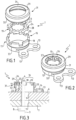
- the retaining device serves to prevent the rotation of a nut 2 around its axis 3, in particular while a screw 4 is being screwed, unscrewed or is in the screwed state in this nut.
- the screwing has the effect of tightening together several parts, here two parts 6 and 7 against each other in the axial direction between the nut 2 and the head 8 of the screw 4.
- the part 6 adjacent to the nut is called the “part to be tightened”, it is for example an aircraft engine casing
- the other part 7, adjacent to the screw head 8, called for example the “inserted part” is for example a component to be fixed on the engine casing, typically by several fastening systems each comprising a nut 2, a screw 4 and a retaining device 1.
- the screw 4 passes through a bore 9 of the part to be tightened 6 and a bore 11 of the inserted part 7. Due to manufacturing tolerances it is not always possible to perfectly align the bores 9 and 11 along the same screwing axis 3, so that if the nut 2 were fixed to the part to be tightened 6, screwing could be impossible. Furthermore, in the applications more particularly targeted, the face of the part to be tightened 6 adjacent to the nut 2 is difficult or completely inaccessible.
- the nut 2 has on its radially outer periphery a connecting conformation 22 with respect to rotations around the screwing axis 3.
- the connecting conformation is a standard conformation, more particularly a groove.
- the retaining device 1 comprises a body 12 equipped with means for fixing to the part to be clamped 6.
- the fixing means are two ears 13 extending radially outwards from the body 12 itself and intended to be fixed to the part to be clamped 6 by rivets 14 ( Figure 3 ) which are only sketched.
- the position of the ears 13 around the axis 3 may vary from one embodiment to another depending on the space available on the surface of the part 6.
- the two ears 13 could, for example, be radially opposite each other.
- the body 12 has the shape of a cylindrical barrel open at its two axial ends, extending in service along the screwing axis 3 or along an axis parallel to the axis 3 but slightly offset laterally relative to the axis 3.
- the threaded member (nut 2) is prevented from rotating relative to the body 12 around an axis parallel to or coincident with the axis 3.
- the body 12 itself being fixed to the part to be tightened 6, the threaded member (nut 2) is prevented from rotating around such an axis relative to the part to be tightened 6.
- the threaded member 2 has freedom of radial movement relative to the part to be tightened 6 to self-center itself on the screw 4.
- the screw is itself positioned by the bores 9 and 11 which, contrary to what is shown schematically, are generally slightly offset laterally relative to each other, in particular due to manufacturing tolerances.
- the coupling opposing relative rotation between the threaded member 2 and the intermediate element 19 is substantially without radial play and without rotational play around the axis 1.
- the grip between the threaded member 2 and the intermediate element 19 is perfectly consistent with what is provided for the application of the retaining torque to the nut 2 during screwing.
- the radial play is fully ensured further from the axis, therefore under lower forces, between the intermediate element 19 and the body 12.
- the complementary conformation is preferably a grooved bore complementary to the groove of the threaded member (nut 2).
- the intermediate element 19 is preferably a ring.
- the ring surrounds the threaded member (nut 2), and is surrounded by a part of the body 12, in particular when the latter is made in the shape of a barrel as indicated previously.
- the means for coupling the intermediate element 19 with the body 12 may be formed on a radially outer surface 27 of the ring, which radially outer surface has said radial clearance J ( Figure 4 ) with a radially inner surface 26 of the body.
- the coupling means between the intermediate element 19 and the body 12 comprise radial teeth 28 which project into housings, here the crenellations 18, of a cylindrical wall which therefore in this example belongs to the body 12, the radial teeth being carried here by the intermediate element 19.
- one face of the housings here the bottom of the notches 18, forms a stop limiting the axial movement of the intermediate element 19 towards the part to be clamped 6.
- the axial movement of the intermediate element 19 is more precisely, in the example shown, limited by the support of the teeth 28 against the bottom of the notches 18.
- the coupling with radial clearance J between the intermediate element 19 and the body 12 also has a rotational clearance R ( Figure 4 ) on either side of an average relative angular position around the axis 1. This rotational play facilitates the radial displacement of the intermediate element 19 relative to the body 12.
- the grooves of the nut 2 and of the ring 19 are more numerous, in particular twice as numerous, than the teeth 28 and the notches 18.
- the stop may be carried by a cap 31 fixed to the body.
- this fixing is achieved by crimping its lower edge 32 behind an oblique shoulder 33 of the body.
- Figure 1 the lower edge of the cap is shown in its conical shape after crimping, this edge being cylindrical before crimping.
- the cap 31 typically comprises a central opening 34, surrounded by a collar forming the stop 29.
- the retaining device can be made from Inconel alloy, for example.
- the stop 79 is made in one piece with the body 62, and is therefore an integral part of the body 62.
- the body 62 and the ring 69 are made jointly by 3D printing, the ring 69 being directly obtained captive in the body 62.
- the housings 68 are windows closed axially, on the side opposite the part to be tightened, by the stop 79, instead of being, as in the example of Figures 1 to 4 , slots open on the side opposite the part, then closed by the cap 31, the installation of which requires additional manufacturing operations.
- the ring 69 is axially captive of the body 62 because the teeth 78 are interposed between the stop 79 and the face of the windows which faces this stop.
- the teeth 78 are engaged in the windows 68 with sufficient freedom of movement to ensure between the ring 69 and the body 62 the radial clearance proposed by the invention.
- the teeth are sufficiently long radially so as not to be able to disengage from the windows 68 but in the event of maximum decentering of the ring 69 in the body 62.
- a structure similar to that of the Figure 5 can also be produced using the MIM (Metal Injection Molding) process using metal powder agglomerated by sintering, as offered in particular by the company Alliance MIM, Zi Foulottière, 22 rue de l'Europe, 25410 Saint-Vit, France.
- MIM Metal Injection Molding
- a nut with a standard connection conformation could be a nut other than than grooved, for example a hexagon nut, in which case the intermediate element could have as a complementary conformation a hexagon socket or a twelve-sided socket.
- the cap could be replaced by crimping a deformable part of the body, or by an elastic snap ring, such as a Circlip, inserted into the bore of the body. If a cap is used, it could be fixed not by crimping, but for example by welding, in particular by spots, or by shrink fitting.
- the body such as 12 could be crimped or snapped onto the part such as 6, in which case the ears such as 13 would not necessarily be present.
Landscapes
- Engineering & Computer Science (AREA)
- General Engineering & Computer Science (AREA)
- Mechanical Engineering (AREA)
- Connection Of Plates (AREA)
- Bolts, Nuts, And Washers (AREA)
- Clamps And Clips (AREA)
- Snaps, Bayonet Connections, Set Pins, And Snap Rings (AREA)
- Dowels (AREA)
Applications Claiming Priority (2)
| Application Number | Priority Date | Filing Date | Title |
|---|---|---|---|
| FR1851435A FR3078118B1 (fr) | 2018-02-20 | 2018-02-20 | Dispositif de retenue pour organe filete, notamment pour ecrou |
| PCT/EP2019/053412 WO2019162146A1 (fr) | 2018-02-20 | 2019-02-12 | Dispositif de retenue pour organe filete, notamment pour ecrou |
Publications (2)
| Publication Number | Publication Date |
|---|---|
| EP3755908A1 EP3755908A1 (fr) | 2020-12-30 |
| EP3755908B1 true EP3755908B1 (fr) | 2025-06-11 |
Family
ID=62222901
Family Applications (1)
| Application Number | Title | Priority Date | Filing Date |
|---|---|---|---|
| EP19708401.5A Active EP3755908B1 (fr) | 2018-02-20 | 2019-02-12 | Dispositif de retenue pour organe filete, notamment pour ecrou |
Country Status (10)
| Country | Link |
|---|---|
| US (1) | US11767874B2 (enExample) |
| EP (1) | EP3755908B1 (enExample) |
| JP (1) | JP7366039B2 (enExample) |
| CN (1) | CN111757988B (enExample) |
| CA (1) | CA3090872A1 (enExample) |
| FR (1) | FR3078118B1 (enExample) |
| MX (1) | MX2020008481A (enExample) |
| PL (1) | PL3755908T3 (enExample) |
| SG (1) | SG11202007599YA (enExample) |
| WO (1) | WO2019162146A1 (enExample) |
Families Citing this family (5)
| Publication number | Priority date | Publication date | Assignee | Title |
|---|---|---|---|---|
| FR3118755B1 (fr) * | 2021-01-13 | 2023-03-24 | Safran Landing Systems | Dispositif de liaison de pièces mécaniques avec jeu axial |
| CA3228156A1 (en) * | 2021-09-14 | 2023-03-23 | Damien Jacky Marc | Nut retaining device and related methods |
| CA3206120A1 (en) * | 2022-07-15 | 2024-01-15 | Electric Line Technologies, LLC | Method and apparatus for securing threaded connections against unwanted rotation |
| CN115681787B (zh) * | 2022-10-21 | 2023-10-24 | 江苏氟豪防腐科技有限公司 | 一种环保型生产用四氟压力容器 |
| US20250198448A1 (en) * | 2023-12-15 | 2025-06-19 | The Boeing Company | Nut retainer assemblies for blind fastener systems, blind fastener systems and methods for assembling nut retainer assemblies on substrates |
Family Cites Families (24)
| Publication number | Priority date | Publication date | Assignee | Title |
|---|---|---|---|---|
| US3180387A (en) * | 1962-10-22 | 1965-04-27 | Dzus Fastener Co | Floating fastener receptacle |
| JPS52151452A (en) * | 1976-06-11 | 1977-12-15 | Sanko Boruto Kk | Locking spring with cap |
| JPS5745450Y2 (enExample) * | 1978-01-12 | 1982-10-06 | ||
| US4227561A (en) * | 1978-05-05 | 1980-10-14 | Deutsch Fastener Corp. | Sealed fastener |
| CA1297709C (en) * | 1986-12-08 | 1992-03-24 | Pac-Fasteners | Laminated nut with one way installation |
| US5203656A (en) * | 1991-09-19 | 1993-04-20 | Hong Kong Disc Lock Company, Limited | Self-centering, self-tightening fastener |
| US5618143A (en) * | 1994-11-02 | 1997-04-08 | Warn Industries, Inc. | Spindle nut and locking device |
| US5674034A (en) * | 1995-03-24 | 1997-10-07 | Bennett; Bruce A. | Locking nut assembly |
| RU2235926C2 (ru) | 1999-04-27 | 2004-09-10 | Образцов Дмитрий Иванович | Самостопорящаяся гайка |
| US7101135B2 (en) * | 2002-07-19 | 2006-09-05 | Bell Helicopter Textron, Inc. | Self-aligning nut plate |
| US7001127B2 (en) * | 2003-10-20 | 2006-02-21 | Hi-Shear Technology | Non-pyrolytically actuated reduced-shock separation fastener |
| NL1028334C2 (nl) | 2005-02-18 | 2006-08-21 | Holmatro Ind Equip | Scharnierboutconstructie met borging. |
| JP2007107701A (ja) | 2005-10-17 | 2007-04-26 | Tetsudo Kizai Kogyo Kk | ボルトまたはナットの緩み止め装置。 |
| CA2690717C (en) | 2007-06-13 | 2016-05-03 | The Monadnock Company | Apparatus and methods for securing a fastener |
| DE102009005334A1 (de) | 2009-01-16 | 2010-07-22 | Neumayer Tekfor Holding Gmbh | Selbstsichernde Schraubverbindung |
| FR2952149B1 (fr) | 2009-11-05 | 2012-02-03 | Jpb Systeme | Dispositif de fixation vissant auto-verrouillable et assemblage ainsi equipe. |
| US10288109B2 (en) * | 2009-11-05 | 2019-05-14 | Jpb Système | Self-locking screwing attachment device and assembly provided with same |
| US8469460B2 (en) * | 2010-06-29 | 2013-06-25 | Arvinmeritor Technology, Llc | Spindle nut assembly |
| US9447811B2 (en) | 2011-06-28 | 2016-09-20 | Nicholas Strumbos | Fastener and retainer assembly |
| JP5478757B1 (ja) | 2013-04-30 | 2014-04-23 | 新日鉄住金エンジニアリング株式会社 | ボルトのゆるみ止め具 |
| FR3019865B1 (fr) * | 2014-04-15 | 2016-05-06 | Snecma | Dispositif de blocage d'ecrou |
| JP6407692B2 (ja) * | 2014-12-10 | 2018-10-17 | 新電元工業株式会社 | 固定部材、組合部材及び組立部品 |
| WO2017020286A1 (zh) | 2015-08-06 | 2017-02-09 | 杨东佐 | 一种锁紧螺母、止转结构、紧固连接组件及结构、安装及拆卸方法、轨道结构、曲轴连杆机构、骨连接装置及骨连接方法、连接轴装置、车轮骨架、自行车珠堵及珠堵装置及车轮架 |
| CN205533703U (zh) | 2016-03-20 | 2016-08-31 | 深圳带路科技有限公司 | 一种防松螺栓装置 |
-
2018
- 2018-02-20 FR FR1851435A patent/FR3078118B1/fr active Active
-
2019
- 2019-02-12 JP JP2020544792A patent/JP7366039B2/ja active Active
- 2019-02-12 MX MX2020008481A patent/MX2020008481A/es unknown
- 2019-02-12 CA CA3090872A patent/CA3090872A1/fr active Pending
- 2019-02-12 WO PCT/EP2019/053412 patent/WO2019162146A1/fr not_active Ceased
- 2019-02-12 US US16/970,541 patent/US11767874B2/en active Active
- 2019-02-12 EP EP19708401.5A patent/EP3755908B1/fr active Active
- 2019-02-12 CN CN201980013974.4A patent/CN111757988B/zh active Active
- 2019-02-12 PL PL19708401.5T patent/PL3755908T3/pl unknown
- 2019-02-12 SG SG11202007599YA patent/SG11202007599YA/en unknown
Also Published As
| Publication number | Publication date |
|---|---|
| WO2019162146A1 (fr) | 2019-08-29 |
| BR112020016892A2 (pt) | 2020-12-15 |
| CN111757988B (zh) | 2022-07-29 |
| FR3078118B1 (fr) | 2020-02-21 |
| PL3755908T3 (pl) | 2025-09-08 |
| EP3755908A1 (fr) | 2020-12-30 |
| SG11202007599YA (en) | 2020-09-29 |
| JP7366039B2 (ja) | 2023-10-20 |
| FR3078118A1 (fr) | 2019-08-23 |
| CA3090872A1 (fr) | 2019-08-29 |
| JP2021514452A (ja) | 2021-06-10 |
| CN111757988A (zh) | 2020-10-09 |
| RU2020130587A (ru) | 2022-03-21 |
| RU2020130587A3 (enExample) | 2022-03-21 |
| US11767874B2 (en) | 2023-09-26 |
| MX2020008481A (es) | 2020-09-28 |
| US20210108670A1 (en) | 2021-04-15 |
Similar Documents
| Publication | Publication Date | Title |
|---|---|---|
| EP3755908B1 (fr) | Dispositif de retenue pour organe filete, notamment pour ecrou | |
| FR2947592A1 (fr) | Dispositif de liaison mecanique d'au moins deux pieces a alesages coaxiaux | |
| EP2689110A1 (fr) | Dispositif d'obturation a verrouillage auto-activable | |
| FR2987881A1 (fr) | Dispositif de raccordement securise, notamment pour canalisation, embout pour ce dispositif et procede de fabrication d'un ecrou associe. | |
| CA2992532A1 (fr) | Assemblage comprenant un goujon de fixation verrouille | |
| EP3159556A1 (fr) | Ecrou etanche | |
| EP1988002B1 (fr) | Dispositif de palier à roulement pour colonne de direction. | |
| FR2930805A1 (fr) | Procede et organe de serrage d'un element de visserie, dispositif de fixation et de serrage | |
| EP3683460B1 (fr) | Boulon equipe d'un dispositif anti-rotation | |
| FR2989755A1 (fr) | Dispositif de compensation d'usure pour engrenage et procede de montage associe. | |
| FR3078759A1 (fr) | Dispositif de poulie pour galet tendeur ou enrouleur | |
| EP0382638B1 (fr) | Ecrou à montage en aveugle et par sertissage sur une paroi quelconque | |
| EP2094978B1 (fr) | Ecrou a collet deformable | |
| FR3094049A1 (fr) | Rotule sphérique | |
| EP2551541B1 (fr) | Procédé d'assemblage d'une bride de fixation autour d'une bague extérieure d'un roulement | |
| EP1092880A1 (fr) | Système à rattrapage de jeu pour fixer deux pièces l'une à l'autre au moyen d'un organe de fixation du type à vis | |
| FR2931218A1 (fr) | Palier a roulement pour systeme de blocage en position d'une colonne de direction de vehicule automobile | |
| FR3102708A1 (fr) | Interface de fixation d’une première pièce sur une deuxième pièce comprenant une collerette en matériaux composite, palier complet comprenant une telle interface et procédé de fabrication d’une telle interface | |
| FR3034476A1 (fr) | Plaque de matage perfectionnee pour assemblage par vis | |
| EP3859174B1 (fr) | Ecrou comportant une rondelle pivotante présentant un orifice de passage excentré, boulon comprenant ledit écrou et assemblage comprenant au moins un tel boulon | |
| EP3983688B1 (fr) | Dispositif de fixation par vissage, avec freinage a l'etat visse | |
| EP0836685A1 (fr) | Montage de butee de debrayage | |
| FR2925443A1 (fr) | Servomoteur pneumatique d'assistance au freinage pour vehicule a cloison interne mobile. | |
| FR3146306A1 (fr) | Pièce de retenue d’un ou plusieurs éléments d’assemblage rotatifs, notamment pour roue de train d’atterrissage d’aéronef | |
| FR2989756A1 (fr) | Dispositif de compensation d'usure pour engrenage comprenant des moyens de retenue axiale. |
Legal Events
| Date | Code | Title | Description |
|---|---|---|---|
| STAA | Information on the status of an ep patent application or granted ep patent |
Free format text: STATUS: UNKNOWN |
|
| STAA | Information on the status of an ep patent application or granted ep patent |
Free format text: STATUS: THE INTERNATIONAL PUBLICATION HAS BEEN MADE |
|
| PUAI | Public reference made under article 153(3) epc to a published international application that has entered the european phase |
Free format text: ORIGINAL CODE: 0009012 |
|
| STAA | Information on the status of an ep patent application or granted ep patent |
Free format text: STATUS: REQUEST FOR EXAMINATION WAS MADE |
|
| 17P | Request for examination filed |
Effective date: 20200914 |
|
| AK | Designated contracting states |
Kind code of ref document: A1 Designated state(s): AL AT BE BG CH CY CZ DE DK EE ES FI FR GB GR HR HU IE IS IT LI LT LU LV MC MK MT NL NO PL PT RO RS SE SI SK SM TR |
|
| AX | Request for extension of the european patent |
Extension state: BA ME |
|
| DAV | Request for validation of the european patent (deleted) | ||
| DAX | Request for extension of the european patent (deleted) | ||
| STAA | Information on the status of an ep patent application or granted ep patent |
Free format text: STATUS: EXAMINATION IS IN PROGRESS |
|
| 17Q | First examination report despatched |
Effective date: 20230125 |
|
| P01 | Opt-out of the competence of the unified patent court (upc) registered |
Effective date: 20230529 |
|
| GRAP | Despatch of communication of intention to grant a patent |
Free format text: ORIGINAL CODE: EPIDOSNIGR1 |
|
| STAA | Information on the status of an ep patent application or granted ep patent |
Free format text: STATUS: GRANT OF PATENT IS INTENDED |
|
| INTG | Intention to grant announced |
Effective date: 20250225 |
|
| GRAS | Grant fee paid |
Free format text: ORIGINAL CODE: EPIDOSNIGR3 |
|
| GRAA | (expected) grant |
Free format text: ORIGINAL CODE: 0009210 |
|
| STAA | Information on the status of an ep patent application or granted ep patent |
Free format text: STATUS: THE PATENT HAS BEEN GRANTED |
|
| AK | Designated contracting states |
Kind code of ref document: B1 Designated state(s): AL AT BE BG CH CY CZ DE DK EE ES FI FR GB GR HR HU IE IS IT LI LT LU LV MC MK MT NL NO PL PT RO RS SE SI SK SM TR |
|
| REG | Reference to a national code |
Ref country code: GB Ref legal event code: FG4D Free format text: NOT ENGLISH |
|
| REG | Reference to a national code |
Ref country code: CH Ref legal event code: EP |
|
| REG | Reference to a national code |
Ref country code: IE Ref legal event code: FG4D Free format text: LANGUAGE OF EP DOCUMENT: FRENCH |
|
| REG | Reference to a national code |
Ref country code: DE Ref legal event code: R096 Ref document number: 602019071005 Country of ref document: DE |
|
| PG25 | Lapsed in a contracting state [announced via postgrant information from national office to epo] |
Ref country code: FI Free format text: LAPSE BECAUSE OF FAILURE TO SUBMIT A TRANSLATION OF THE DESCRIPTION OR TO PAY THE FEE WITHIN THE PRESCRIBED TIME-LIMIT Effective date: 20250611 Ref country code: ES Free format text: LAPSE BECAUSE OF FAILURE TO SUBMIT A TRANSLATION OF THE DESCRIPTION OR TO PAY THE FEE WITHIN THE PRESCRIBED TIME-LIMIT Effective date: 20250611 |
|
| REG | Reference to a national code |
Ref country code: LT Ref legal event code: MG9D |
|
| PG25 | Lapsed in a contracting state [announced via postgrant information from national office to epo] |
Ref country code: NO Free format text: LAPSE BECAUSE OF FAILURE TO SUBMIT A TRANSLATION OF THE DESCRIPTION OR TO PAY THE FEE WITHIN THE PRESCRIBED TIME-LIMIT Effective date: 20250911 Ref country code: GR Free format text: LAPSE BECAUSE OF FAILURE TO SUBMIT A TRANSLATION OF THE DESCRIPTION OR TO PAY THE FEE WITHIN THE PRESCRIBED TIME-LIMIT Effective date: 20250912 |
|
| REG | Reference to a national code |
Ref country code: NL Ref legal event code: MP Effective date: 20250611 |
|
| PG25 | Lapsed in a contracting state [announced via postgrant information from national office to epo] |
Ref country code: BG Free format text: LAPSE BECAUSE OF FAILURE TO SUBMIT A TRANSLATION OF THE DESCRIPTION OR TO PAY THE FEE WITHIN THE PRESCRIBED TIME-LIMIT Effective date: 20250611 |
|
| PG25 | Lapsed in a contracting state [announced via postgrant information from national office to epo] |
Ref country code: HR Free format text: LAPSE BECAUSE OF FAILURE TO SUBMIT A TRANSLATION OF THE DESCRIPTION OR TO PAY THE FEE WITHIN THE PRESCRIBED TIME-LIMIT Effective date: 20250611 |
|
| PG25 | Lapsed in a contracting state [announced via postgrant information from national office to epo] |
Ref country code: RS Free format text: LAPSE BECAUSE OF FAILURE TO SUBMIT A TRANSLATION OF THE DESCRIPTION OR TO PAY THE FEE WITHIN THE PRESCRIBED TIME-LIMIT Effective date: 20250911 |
|
| PG25 | Lapsed in a contracting state [announced via postgrant information from national office to epo] |
Ref country code: LV Free format text: LAPSE BECAUSE OF FAILURE TO SUBMIT A TRANSLATION OF THE DESCRIPTION OR TO PAY THE FEE WITHIN THE PRESCRIBED TIME-LIMIT Effective date: 20250611 |
|
| PG25 | Lapsed in a contracting state [announced via postgrant information from national office to epo] |
Ref country code: NL Free format text: LAPSE BECAUSE OF FAILURE TO SUBMIT A TRANSLATION OF THE DESCRIPTION OR TO PAY THE FEE WITHIN THE PRESCRIBED TIME-LIMIT Effective date: 20250611 |
|
| PG25 | Lapsed in a contracting state [announced via postgrant information from national office to epo] |
Ref country code: PT Free format text: LAPSE BECAUSE OF FAILURE TO SUBMIT A TRANSLATION OF THE DESCRIPTION OR TO PAY THE FEE WITHIN THE PRESCRIBED TIME-LIMIT Effective date: 20251013 |
|
| REG | Reference to a national code |
Ref country code: AT Ref legal event code: MK05 Ref document number: 1802473 Country of ref document: AT Kind code of ref document: T Effective date: 20250611 |