EP3755853B1 - Verschlusshalter für einen türverschluss - Google Patents
Verschlusshalter für einen türverschluss Download PDFInfo
- Publication number
- EP3755853B1 EP3755853B1 EP19711808.6A EP19711808A EP3755853B1 EP 3755853 B1 EP3755853 B1 EP 3755853B1 EP 19711808 A EP19711808 A EP 19711808A EP 3755853 B1 EP3755853 B1 EP 3755853B1
- Authority
- EP
- European Patent Office
- Prior art keywords
- adjusting
- receiving element
- closure
- bearing
- rear handle
- Prior art date
- Legal status (The legal status is an assumption and is not a legal conclusion. Google has not performed a legal analysis and makes no representation as to the accuracy of the status listed.)
- Active
Links
Images


Classifications
-
- E—FIXED CONSTRUCTIONS
- E05—LOCKS; KEYS; WINDOW OR DOOR FITTINGS; SAFES
- E05B—LOCKS; ACCESSORIES THEREFOR; HANDCUFFS
- E05B15/00—Other details of locks; Parts for engagement by bolts of fastening devices
- E05B15/02—Striking-plates; Keepers; Bolt staples; Escutcheons
- E05B15/0205—Striking-plates, keepers, staples
- E05B15/024—Striking-plates, keepers, staples adjustable
- E05B15/025—Striking-plates, keepers, staples adjustable the striker being movable by a screw/nut
Definitions
- the present invention relates to a lock holder for a lock, in particular a door lock, according to the preamble of patent claim 1.
- Locking retainers are used for openings that can be locked, such as doors, hatches and windows. As part of a lock, they enable locking elements, such as door leaves, hatch bulkheads, flaps, window sashes or covers, to be locked to a frame surrounding the opening.
- a locking element of the lock such as a bolt, a sash or a lock latch, engages with the locking retainer in such a way that it is behind a The rear grip of the bolt holder engages. The bolt holder and the locking element thus form a releasable lock.
- the locking element and the locking holder are arranged on the locking element or the frame.
- the locking element is arranged on the locking element and the locking holder on the frame or the locking holder is arranged on the locking element and the locking element on the frame.
- the locking element locked to the frame In order for the locking element locked to the frame to close the opening evenly and also compress sealing elements arranged between the frame and the locking element, such as sealing profiles or sealing beads, to seal it, it is often necessary to align the rear handle in order to compensate for manufacturing tolerances, wear effects and the like that occur in practice.
- the aim of this alignment is to position the rear handle in such a way that the locking element locked by means of the locking element and the lock holder has a uniform distance from the frame and at the same time exerts sufficient contact pressure on the sealing elements.
- the FR 2 400 100 A1 discloses a bolt holder in which a rear handle can be adjusted via several screws.
- the screws have a head and a shoulder arranged below the head, with the rear grip being arranged partially between the head and the shoulder so that it follows a movement of the screw.
- this alignment is achieved during assembly by arranging spacers, for example in the form of shims or similar, between the frame or locking element and a base element of the locking holder, by means of which the rear handle is arranged on the frame or locking element.
- spacers for example in the form of shims or similar
- this alignment often proves to be very complex, since the base element has to be detached from the frame or locking element in order to attach a spacer and then reattached.
- the spacers only allow adjustment in discrete steps, which depend on the thickness of the available spacers, which means that a uniform distance and contact pressure can only be achieved to a limited extent.
- the object of the present invention is therefore to provide a closure holder which enables simpler and more precise alignment.
- the adjustment device allows the distance of the rear handle to be easily adjusted from the base element and thus from the frame and/or the locking element.
- the alignment of the rear handle can be infinitely adjusted regardless of the thickness of the available spacers. It is not necessary to detach the base element from the frame or the locking element, but this is also possible.
- a uniform distance of the locking element in the locked position from the frame and thus a uniform contact pressure on the sealing elements can be achieved easily and with high precision by adjusting the distance of the rear handle.
- parts of the adjusting device are movable transversely to the base element to produce an adjusting movement.
- the distance of the rear grip can be adjusted in a particularly advantageous manner.
- the adjusting device is designed in such a way that the contact pressure of a sealing element can be adjusted.
- the sealing element can be arranged between a locking element and a frame.
- the sealing element can be designed as a circumferential door seal.
- the distance of the rear handle can be adjusted to achieve different closing positions.
- the closing positions correspond to the position of the locking element in relation to the frame in the closed position.
- Each closing position can therefore correspond to a position of the locking element in relation to the frame.
- the distance of the The distance of the rear handle and therefore also the contact pressure can be continuously adjustable.
- the adjustment direction of the distance of the rear handle can correspond to the closing direction of the locking element.
- the closing direction is perpendicular to the locking element in the closed position.
- the distance between the locking element and the frame can be different in each closing position.
- the sealing element arranged between the locking element and the frame is compressed more strongly, so that the seal is improved.
- the closing angle of the locking element can also be adjusted by changing the distance. The closer the locking element is to the frame in the closed position, the smaller the closing angle. If no sealing element is provided, the closing angle would therefore be 0 degrees when the locking element is closed.
- the rear handle is arranged on a receiving element.
- the receiving element and the rear handle can be adjusted together using the adjusting device.
- the receiving element allows the rear handle to be arranged so that it can move in a structurally advantageous manner.
- the receiving element can enable the rear handle to be replaced.
- the joint adjustability of the receiving element and the rear handle means that a structurally simple, compact design can be achieved.
- a guide for guiding the adjusting movements of the receiving element is advantageous.
- the receiving element can be guided in a structurally simple manner by means of a guide.
- the play of the receiving element transverse to the adjusting movements of the adjusting device can be reduced, in particular suppressed, by the guide.
- the guide is formed from a guide area on the base element side and a guide area on the receiving element side, which abut one another in the manner of a sliding guide. abutting surfaces of the two guide areas enable positive guidance up to one axial degree of freedom.
- the guide areas can be designed to complement one another.
- the guide areas can be designed to be positive, in particular along several axes transverse to the direction of the actuating movements of the receiving element.
- the receiving element can be prevented from escaping from the guide in a simple manner.
- the guide areas can also transmit locking forces acting on the lock holder, which act on the lock holder from the outside, for example via the locking element or the locking element. Loading the actuating device with these locking forces, in particular transverse to the direction of the actuating movement of the actuating device and/or the receiving element, can be avoided, thereby reducing the risk of damage to the actuating device.
- the guide has a guide structure that engages in a complementary guide structure for the linear guide of the receiving element.
- the guide structures can easily provide additional, secure guidance in the form of guide rails and/or guide grooves.
- the base element and the receiving element are shaped like plug-in connection elements.
- the shape like plug-in connection elements can enable a simple and reliable connection of the base element to the receiving element.
- the actuating movement can be guided in a structurally simple manner by a complementary shape of adjacent areas of the stretch connection elements.
- the base element can completely or partially encompass sides of the receiving element, in particular opposite sides, or can be encompassed by the receiving element.
- a pin of the base element engages in a plug-in element of the receiving element.
- a plug connection can be achieved that is secured against movements along several directions of movement, in particular along all directions of movement lying in one plane.
- the adjusting device has a bearing opening and an adjusting element and that the adjusting element is connected to the base element.
- the adjusting device has a counter thread.
- the adjusting element can enable simple actuation of the adjusting device to adjust the distance of the rear grip from the base element.
- the counter thread can connect the adjusting device to the base element or the receiving element.
- the adjusting device can be connected to the receiving element or the base element via the bearing opening.
- the adjusting element and/or the counter thread and/or the bearing opening can be designed to be detachable from one another in order to dismantle the adjusting device.
- the adjusting element and the counter thread and/or the bearing opening can work together in the manner of a rotor-stator system.
- the adjusting device can in particular be designed in the manner of a lifting thread or a spindle drive.
- two adjusting devices are provided and arranged on both sides of the rear handle.
- Two adjusting devices allow an inclination relative to the base element.
- the rear handle can be inclined relative to the base element by setting different distances.
- the adjustable inclination of the rear handle can be used to compensate for a distortion of the frame and/or the locking element.
- An arrangement of the adjusting devices on both sides of the rear handle allows a reliable and stable adjustment of the distance of the rear handle against unwanted movements. from the base element.
- the two adjusting devices can support the rear handle in the manner of a two-point support along the adjusting direction.
- the adjusting element comprises a thread for connection to the counter thread arranged on the base element and/or a groove for rotationally movable but axially fixed arrangement on the receiving element.
- the thread of the adjusting element can interact as an external thread with the counter thread of the base element designed as an internal thread or as an internal thread with the counter thread of the base element designed as an external thread.
- the distance of the rear grip from the base element can be adjusted continuously by a relative rotation of the thread with respect to the counter thread.
- the rotational movement of the adjusting element can be converted into a linear adjusting movement of the receiving element.
- the adjusting element can be designed in a screw shape with a head diametrically opposite the thread.
- the head preferably comprises a drive area, in particular in the form of a hexagon socket, external hexagon, hexagon socket, slot or Phillips, for driving the adjusting element by a correspondingly designed drive device, such as a manual screwdriver or a drill driver.
- the groove allows the adjusting element to be mounted on the receiving element so that it can rotate freely in the circumferential direction.
- the groove is preferably arranged between the thread and the head of the adjusting element. It can be designed in the manner of a circumferential groove with a smaller radial diameter than the thread and/or the head of the adjusting element.
- the receiving element comprises the bearing opening of the adjusting device with a bearing area for transmitting thrust and tensile forces and a larger insertion area for inserting the adjusting element.
- the bearing area can have an inner diameter which is smaller than the outer diameter of the thread and/or the head of the adjusting element.
- the closing element can therefore be prevented from escaping from the bearing area along the axial direction by means of a positive fit.
- the bearing area can be designed in such a way that it receives the adjusting element, in particular a groove of the adjusting element, in a substantially positive fit. By means of a substantially positive fit of the adjusting element, the latter can be fixed along its axial direction.
- the insertion area can have an inner diameter which is larger than the outer diameter of the thread and/or the head of the adjusting element.
- the adjusting element can be inserted into the larger insertion area of the bearing opening with the smaller thread-side and/or head-side end first.
- the adjusting element and/or the receiving element can be moved substantially transversely to the adjustment direction.
- the movement of the adjusting element can preferably take place when the adjusting element is not yet arranged on the base element.
- the movement of the receiving element can preferably take place when the adjusting element is already arranged on the base element.
- To transfer from the storage area to the insertion area the movement can take place in the opposite direction.
- the storage area and the insertion area can form two diametrically opposite ends of the storage opening.
- the bearing area and the insertion area form a keyhole-shaped bearing opening.
- a keyhole-shaped bearing opening in which the bearing area and the insertion area are essentially round and connected to one another by an elongated hole, enables a structurally simple transfer of the Adjusting element between the insertion area and the bearing area.
- the bearing area and the insertion area can also form a bearing opening of a different geometric shape, for example a triangular, trapezoidal, kite or L-shaped bearing opening, in particular with rounded corner areas.
- the bearing area and the insertion area have circular openings with different diameters.
- the openings of the bearing area and the insertion area can overlap.
- the opening of the insertion area can be larger than the opening of the bearing area.
- the bearing areas of at least two bearing openings face each other.
- their adjusting elements can mutually secure against escaping from the bearing area by arranging the bearing openings with bearing areas facing each other. This is because the adjusting elements would have to be transferred from the bearing area to the insertion area in order to be able to escape. Due to the arrangement of the bearing areas facing each other, the adjusting elements would have to move in opposite directions, which is not possible in particular with adjusting elements arranged on the base element. In addition, a movement of the receiving element that would transfer the adjusting elements to the insertion areas can also be prevented. This is because the receiving element would have to be moved in two opposite directions at the same time.
- the adjustment device allows the distance of the rear handle to the base element and thus to the frame and/or the locking element to be easily adjusted.
- the alignment and/or the locking element is not necessary, but is nevertheless possible.
- a uniform distance between the locking element in the closed position and the frame and a uniformly applied contact pressure on the sealing elements can be achieved by adjusting the distance of the rear handle.
- an adjusting element is inserted into an insertion area of a receiving element and the receiving element and the adjusting element are displaced against each other transversely to the insertion direction in order to engage a groove in a bearing area.
- the adjusting element can be arranged axially fixed to the receiving element in a structurally simple and quick manner in order to adjust the distance of the rear grip.
- the adjusting device can comprise the adjusting element, the insertion area and the bearing area.
- a device with a closing element, in particular a door, a frame on which the closing element is pivotally mounted and a closure holder for adjusting the closed position of the closing element wherein the closure holder is designed in the manner described above.
- the position of the closing element in the closed position relative to the frame can be determined via the closure holder.
- the device can comprise a sealing element which is arranged in the closed position to seal between the frame and the closing element.
- the sealing element can prevent gas exchange between the interior space which can be closed with the closing element and the exterior space.
- the closure holder can the closed position of the locking element can be adjusted in such a way that the sealing element is compressed to different degrees.
- the locking holder can also compensate for manufacturing tolerances.
- the locking holder can be arranged on one side of the frame and the locking element can be mounted on the opposite side of the frame. All elements of the device can be designed in the way already described with regard to the locking holder.
- a latch in particular a pivotable latch, can be arranged on the locking element to lock the locking element in the closed position.
- the latch can be designed as a cam tongue. The latch can engage in the rear grip of the lock holder to lock the locking element in different locking positions.
- the device comprises several closure holders. These can be arranged at least partially on the circumference of the closing element. Several closure holders can ensure that the sealing element has a constant contact pressure over the circumference of the closing element. Deformations of the closing element, such as can occur when only one closure holder is used, can thus be prevented.
- Lock holders 1 are used for locking door locks, for example. They have a rear handle 4.2, which is gripped behind by a locking element, such as a bolt or a lock latch, of a lock for locking a locking element, such as a door leaf, hatch bulkhead, window leaf, lid or flap, on a frame.
- a locking element such as a bolt or a lock latch
- the locking element is typically arranged on the locking element and the lock holder 1 on the frame.
- the lock holder 1 can also be arranged on the locking element and the locking element on the frame.
- the locking element and the rear handle 4.2 form a lock between the frame and the locking element.
- An opening surrounded by the frame which can be a door, hatch or window, for example, can be locked in a simple manner in this way.
- the closure holder 1 In order to enable the opening to be closed evenly by the closing element and to compress a sealing element arranged between the frame and the closing element, such as a sealing lip or sealing bead, for sealing, the closure holder 1 must be aligned.
- the closure holder 1 according to the invention enables simple and precise alignment.
- the frame does not have to be a separate element.
- the frame can also be formed by the edge of a wall surrounding the opening or the like.
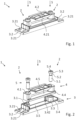
- FIG.1 A mounted closure holder 1 is shown in perspective.
- This closure holder 1 is in Fig.2 shown as an exploded view, which makes its individual elements easier to recognize.
- the lock holder 1 has fastening areas 3.2 for fastening to or in a frame or a locking element.
- connecting means such as screws or rivets, are inserted into fastening recesses 3.21 in the fastening areas 3.2 and connected to the frame, the locking element or an element arranged thereon.
- the closure holder 1 essentially comprises four elements: a base element 3, a receiving element 4 and two adjusting elements 5. However, a single closing element 5 would also be sufficient for the distance adjustment according to the invention.
- the closure holder 1 can also comprise other elements.
- the elongated base element 3 and the essentially C-profile-shaped receiving element 4 are preferably made of injection-molded plastic, but can also have metal elements, in particular in the area of the rear handle 4.2, or be made entirely of metal.
- the rear handle 4.2 is arranged on the receiving element 4 and, in the assembled state, runs essentially parallel to the side 4.5 of the receiving element 4 which is opposite it along an adjustment direction S which runs parallel to the adjustment movement of the rear handle 4.2. Together with the side 4.5, the rear handle 4.2 encloses a substantially empty space into which the locking element can engage for locking. To do this, the locking element engages behind the rear handle 4.2, which prevents a movement of the locking element to release the opening relative to the lock holder 1, in particular against the adjustment direction S, until the locking is released, for example by pivoting away. or pulling away the locking element.
- the side 4.5 and the rear grip 4.2 form an area of the receiving element 4 with a C-shaped cross-section. In order to be gripped as securely as possible by the locking element, the side 4.21 of the rear grip facing the bolt for locking has a substantially W-shaped profile.
- Each of the adjusting elements 5 forms, together with a counter thread 3.1 and a bearing opening 4.1, an adjusting device 2 with which the distance of the rear handle 4.2 can be adjusted relative to the base element 3.
- a single adjusting device 2 would also be sufficient for adjusting the distance of the rear handle 4.2 according to the invention, whereby the closure holder 1 would then essentially consist of three elements.
- the adjusting device 2 enables a movement of the rear handle 4.2 relative to the base element 3 along the adjustment direction S in the manner of a spindle drive by moving the receiving element 4, which carries the rear handle 4.2 and can be adjusted together with it, either towards the base element 3 or away from the base element 3 along the adjustment direction S.
- the adjusting device 2 has a bearing opening 4.1 arranged on the receiving element 4, which is in particular formed integrally with the receiving element 4.
- the adjusting element 5 is mounted on one side in the bearing opening 4.1. With its opposite end, the adjusting element 5 interacts with the counter thread 3.1 attached to the base element 3. To change the distance between the base element 3 and the rear handle 4.2, the adjusting element 5 is rotated about its longitudinal axis.
- This rotary movement is converted into a linear movement of the adjusting element 5 by the interaction of the adjusting element 5 with the counter thread 3.1. Due to this linear movement, the actuating element 5 together with the receiving element 4, which carries the actuating element 5 freely rotating in the bearing opening 4.1, is pulled towards or pushed away from the base element 3 depending on the direction of rotation. The distance is therefore adjusted in the manner of a lifting thread or a spindle drive mounted on one side in the receiving element 4 with the base element 3 as a spindle nut.
- the bearing opening 4.1 can also be arranged on the base element 3 and the counter thread 3.1 on the receiving element 4. It is also possible that in an adjusting device 2 according to the invention, individual or several parts of the adjusting device 2 described above are dispensed with.
- the cylindrical actuating element 5 has a thread 5.1, which serves to connect the actuating element 5 to the base element 3.
- the actuating element 5 On the side diametrically opposite the thread 5.1, the actuating element 5 has a head 5.3, which forms the end of the actuating element 5.
- the head 5.3 has a larger radius than the thread 5.1, but can also have the same radius as the thread 5.1.
- the head 5.3 comprises a drive area 5.4, which is designed in the manner of a hexagon socket.
- the drive area 5.4 can be designed in the form of an external hexagon, hexagon socket, slot or Phillips slot.
- the actuating element 5 is coupled to a drive device (not shown), such as a screwdriver or a drill driver, to drive the actuating movement via this drive area 5.4.
- the actuating element 5 has an essentially helical geometry overall.
- the adjusting element 5 has a circumferential taper with a groove 5.2.
- the groove 5.2 is limited by the thread 5.1 and the head 5.3, but can also have a distance from these.
- the groove 5.2 enables a rotatable, but axially fixed arrangement on the receiving element 4.
- the groove 5.2 is designed in the manner of a sudden inwardly retracting radius change. This enables a positive mounting of the groove 5.2 in the bearing opening 4.1. Thrust and tensile forces can be transferred from the adjusting element 5 to the receiving element 4 to adjust the distance from the base element 3.
- Fig.3 the receiving element 4 is according to Fig.1 shown in more detail.
- the bearing openings 4.1 are arranged on both sides of the rear handle 4.2.
- the adjusting devices 2 are arranged on both sides of the rear handle 4.2.
- the two adjusting devices 2 allow not only the distance of the rear handle 4.2 to be adjusted from the base element 3, but also the inclination of the rear handle 4.2.
- the adjustable inclination of the rear handle 4.2 can compensate for any distortion of the locking element and/or the frame caused by manufacturing tolerances or usage. Different distances between the rear handle 4.2 and the base element 3 are set using the adjusting devices 2, which results in an inclination of the rear handle 4.2 from the base element 3.
- the adjusting element 5 of the adjusting device 2 is mounted in a bearing opening 4.1 of the receiving element 4, which also belongs to the adjusting device 2.
- the bearing opening 4.1 has a bearing area 4.11 and an insertion area 4.12. In comparison to the bearing area 4.11, the insertion area 4.12 is larger. This makes it possible to insert the adjusting element 5 with the thread 5.1 and/or the head 5.3 first into the insertion area 4.12.
- the inner radius of the insertion area 4.12 is at least as large as the outer diameter of the thread 5.1 and/or the head 5.3 of the adjusting element 5.
- the bearing area 4.11 has an inner diameter below the outer diameter of the thread 5.1 and/or the head 5.3 of the adjusting element 5. Due to this smaller inner diameter of the bearing area 4.11 prevents an adjusting element 5 mounted in the bearing area 4.11 from escaping from the bearing area 4.11 in the axial direction. An axial restriction of the freedom of movement of the adjusting element 5 is achieved.
- the radius of the bearing area 4.11 essentially corresponds to the outer diameter of the groove 5.2 of the adjusting element 5.
- the axial dimension of the bearing area 4.11 essentially corresponds to the axial length of the groove 5.2. In this way, the groove 5.2 can be mounted in a form-fitting manner in the bearing area 4.11. The thrust and tensile forces are thus transferred from the adjusting element 5 to the receiving element 4 to adjust the distance from the base element 3.
- the bearing area 4.11 and the insertion area 4.12 form a keyhole-shaped bearing opening 4.1, in which the two essentially circular areas 4.11 and 4.12 are connected to one another via an elongated hole running between the two areas 4.11, 4.12.
- the smaller diameter of this elongated hole essentially corresponds to the inner diameter of the bearing area 4.11.
- Fig.1 shown basic element 3 based on the representation in Fig.4 described in more detail. It has a bar-shaped geometry with essentially less height than length.
- the base element 3 has an insertion area 3.5 in the middle, into which the receiving element 4 is inserted for mounting the closure holder 1.
- the insertion area 3.5 is surrounded by a frame-like guide area 3.4 for guiding the adjustment movement of the receiving element 4.
- This guide area 3.4 interacts with a circumferential guide area 4.4 of the Fig.3 shown receiving element 4.
- both guide areas 3.4, 4.4 form a guide for guiding the adjustment movement of the receiving element 4.
- They lie in the manner of a sliding guide with the contact surfaces 3.41, 4.41 to each other.
- the guide area 3.4 is designed to be complementary to the guide area 4.4 and accommodates it, which enables a positive guidance of the movement of the receiving element 4.
- Closing forces acting transversely to the adjusting device 2 are transferred from the receiving element 4 to the base element 3 by the guide 3.4, 4.4.
- the actuating device 2 and the adjusting element 5 are prevented from being subjected to these closing forces, which is disadvantageous in terms of connection technology.
- the adjusting devices 2 and in particular the adjusting elements 5 are therefore outside the force flow.
- the guide area 4.4 and the bearing opening 4.1 are arranged in relation to one another in such a way that, in the assembled closure holder 1, in which the guide area 4.4 rests against the guide area 3.4, the adjusting element 5 fixed via the counter thread 3.1 cannot be transferred from the bearing area 4.11 into the insertion area 4.12. In the assembled state, an unintentional emergence of the adjusting element 5 from the bearing opening 4.1 and thus disassembly of the adjusting device 2 as well as a detachment of the receiving element 4 from the base element 3 is prevented.
- the base element 3 also has two rail-shaped guide structures 3.42. These are formed in one piece with the guide region 3.4, whereby the guide structures 3.42 can also be separate elements spaced apart from the guide region 3.4 and in particular a single guide structure 3.42 according to the invention.
- the guide structures 3.42 arranged in a track-like manner engage in groove-shaped guide structures 4.42 of the receiving element 4 that are complementary to them. By engaging in the guide structures 4.42, the guide structures 3.42 lying next to one another on the same side of the base element 3 enable safe guidance of the actuating movement in the manner of guide rails and guide grooves.
- the base element 3 and the receiving element 4 are designed by the guide 3.4, 4.4 in the manner of interacting plug-in connection elements.
- the base element 3 partially encloses the receiving element 4 with the guide area 3.4 along the Fig.5 shown cutting plane.
- Two pins 3.3 protrude from the side of the base element 3 facing the receiving element 4. These each have a counter thread 3.1, which cooperates as part of the adjusting device 2 to connect the adjusting element 5 with its thread 5.1.
- the counter thread 3.1 is designed as an internal thread of a threaded hole.
- the pins 3.3 are inserted into plug-in elements 4.3 of the receiving element 4.
- the plug-in elements 4.3 each have the bearing openings 4.1 of the adjusting devices 2.
- only one pin 3.3 and one plug-in element 4.3 can optionally be provided.
- the circumferential inner surface of the plug-in element 4.3 and the circumferential outer surface of the pin 3.3 additionally guide the adjusting movement of the rear handle 4.2.
- the counter thread 3.1 and the bearing area 4.11 of the bearing opening 4.1 are aligned with each other when the pin 3.3 is inserted into the plug-in element 4.3.
- the adjusting element 5 When assembling the lock holder 1 and assembling the adjusting device 2, the adjusting element 5 is first inserted into the insertion area 4.12 of the receiving element 4 and moved transversely to the insertion direction so that the groove 5.2 engages in the bearing area 4.11.
- the adjusting element 5 mounted in the receiving element 4 is then connected to the base element 3 by means of the thread 5.1 and the counter thread 3.1.
- the receiving element 4 is then inserted into the insertion area 3.5 used, with the guide areas 3.4, 4.4 and the guide structures 3.42, 4.42 engaging with each other like a plug connection.
- the thread 5.1 and the counter thread 3.1 are first engaged and then the receiving element 4 is plugged onto the adjusting element 5 in such a way that the adjusting element 5 is inserted into the insertion area 4.12.
- the receiving element 4 is then moved relative to the adjusting element 5 and the base element 3 in order to transfer the adjusting element 5 into the bearing area 4.11.
- the second alternative assumes that the receiving element 4 can be spaced apart from the base element 3 via the adjusting device 2 in such a way that the guide areas 3.4, 4.4 do not abut one another and the guide structures 3.42, 4.42 do not engage with one another.
- Fig. 5 and Fig. 6 show sectional views of the closure holder 1 according to Fig.1 for different distances between the rear handle 4.2 and the base element 3.
- Fig.5 there is a smaller distance D1 between the base element 3 and the receiving element 4.
- the guide areas 3.4 and 4.4 lie against each other with their contact surfaces 3.41, 4.41.
- the pin 3.3 engages in the plug-in element 4.3. Closing forces acting transversely to the axis of the adjusting element 5 can be transferred from the receiving element 4 to the base element 3 without affecting the adjusting element 5.
- the adjusting element 5 is rotated about its longitudinal axis to actuate the adjusting device 2. Through the interaction of the thread 5.1 and the counter-thread 3.1, this rotary movement is converted into an axial longitudinal movement of the adjusting element 5.
- a pushing or pulling force exerted by the axial longitudinal movement is transmitted to the receiving element 4 by the axial fixation of the adjusting element 5 described above.
- the receiving element 4 is moved away from or towards the base element 3 by the pushing or pulling force and is guided by the guide 3.4, 4.4.
- This guide is additionally guided by the Fig. 5 and Fig. 6 Management structures 3.42, 4.42 (not shown) are supported.
- the adjusting element 5 is rotated, for example, anti-clockwise around its longitudinal axis.
- the adjusting element 5 is thereby rotated out of the counter thread 3.1, which leads to a linear movement of the adjusting element 5 together with the receiving element 4 and the rear grip 4.2 against the adjustment direction S.
- the adjusting element 5 is rotated until the larger distance D2 is set.
Landscapes
- Hinges (AREA)
- Pressure Vessels And Lids Thereof (AREA)
- Operating, Guiding And Securing Of Roll- Type Closing Members (AREA)
Description
- Die vorliegende Erfindung betrifft einen Verschlusshalter für einen Verschluss, insbesondere einen Türverschluss, gemäß dem Oberbegriff des Patentanspruchs 1.
- Verschlusshalter kommen bei verschließbar ausgestalteten Öffnungen, wie beispielsweise Türen, Luken und Fenstern, zum Einsatz. Dort ermöglichen sie als Teil eines Verschlusses das Verriegeln von Schließelementen, wie beispielsweise Türflügeln, Lukenschotten, Klappen, Fensterflügeln oder Deckeln, an einer die Öffnung umgebenden Zarge. Dabei gelangt ein Riegelelement des Verschlusses, wie ein Riegel, ein Vorreiber oder eine Schlossfalle, derart mit dem Verschlusshalter in Eingriff, dass es hinter einem Hintergriff des Verschlusshalters greift. Der Verschlusshalter und das Riegelelement bilden hierdurch eine lösbare Verriegelung.
- Zu diesem Zwecke sind das Riegelelement und der Verschlusshalter an dem Schließelement oder der Zarge angeordnet. Entweder ist das Riegelelement an dem Schließelement und der Verschlusshalter an der Zarge angeordnet oder der Verschlusshalter ist an dem Schließelement und das Riegelelement an der Zarge angeordnet.
- Um das Schließelement zum Öffnen freizugeben, ist es erforderlich, das Riegelelement von dem Hintergriff zu lösen. Dies erfolgt typischerweise über einen Handgriff oder eine Schlüsselmechanik, welche das Riegelelement von dem Hintergriff durch eine Dreh- oder Längsbewegung derart wegbewegt, dass der Hintergriff nicht mehr von dem Riegelelement hintergriffen wird. Die Verriegelung des Riegelelements und des Verschlusshalters wird gelöst. Das Schließelement ist von der Zarge entriegelt und die Öffnung kann durch das Schließelement freigegeben werden.
- Damit das an der Zarge verriegelte Schließelement die Öffnung gleichmäßig verschließt und dabei auch zwischen der Zarge und dem Schließelement angeordnete Dichtungselemente, wie Dichtprofile oder Dichtwülste, zur Abdichtung komprimiert, ist häufig eine Ausrichtung des Hintergriffs erforderlich, um in der Praxis auftretende Fertigungstoleranzen, Verschleißeffekte und Ähnliches auszugleichen. Ziel dieser Ausrichtung ist es, den Hintergriff derart zu positionieren, dass das mittels des Riegelelements und des Verschlusshalters verriegelte Schließelement einen gleichmäßigen Abstand zu der Zarge aufweist und zugleich einen ausreichenden Anpressdruck auf die Dichtungselemente ausübt.
- Die
FR 2 400 100 A1 US 3 469 877 A undWO 2007/006076 A1 verwiesen. - Typischerweise erfolgt diese Ausrichtung bei der Montage durch die Anordnung von Abstandsstücken, beispielsweise nach Art von Unterlegplättchen oder Ähnlichem, zwischen der Zarge oder dem Schließelement und einem Grundelement des Verschlusshalters, mittels welchem der Hintergriff an der Zarge oder dem Schließelement angeordnet ist. Diese Ausrichtung erweist sich in der Praxis jedoch häufig als sehr aufwendig, da das Grundelement zum Anbringen eines Abstandsstücks von der Zarge oder dem Schließelement gelöst und anschließend wieder befestigt werden muss. Die Abstandsstücke ermöglichen nur eine Anpassung in diskreten Schritten, welche von den Dicken der verfügbaren Abstandsstücke abhängen, wodurch ein gleichmäßiger Abstand und Anpressdruck nur eingeschränkt erzielt werden kann. Zudem sind nachträgliche Anpassungen der Ausrichtung des Hintergriffs, wie sie beispielsweise aufgrund von Verschleißeffekten, der Verwendung anderer Dichtungselemente oder einem Verziehen der Zarge und/oder des Schließelements erforderlich werden, nur eingeschränkt und unter einem sehr hohen Aufwand möglich. Denn auch in diesen Fällen lässt sich der Verschlusshalter nur durch ein aufwendiges Lösen der Verbindung mit der Zarge oder dem Schließelement einstellen.
- Die Aufgabe der vorliegenden Erfindung liegt daher darin, einen Verschlusshalter anzugeben, welcher eine einfachere und präzisere Ausrichtung ermöglicht.
- Diese Aufgabe wird bei einem Verschlusshalter der eingangs genannten Art durch die kennzeichnenden Merkmals des Patentanspruchs 1 gelöst.
- Durch die Stellvorrichtung kann der Abstand des Hintergriffs gegenüber dem Grundelement und damit zu der Zarge und/oder dem Schließelement auf einfache Art und Weise eingestellt werden. Die Ausrichtung des Hintergriffs kann unabhängig von der Dicke verfügbarer Abstandsstücke stufenlos erfolgen. Ein Lösen des Grundelements von der Zarge oder dem Schließelement ist nicht erforderlich, gleichwohl auch möglich. Ein gleichmäßiger Abstand des Schließelements in der verriegelten Stellung zu der Zarge und damit ein gleichmäßig ausgeübter Anpressdruck auf die Dichtungselemente kann durch Einstellen des Abstands des Hintergriffs auf einfache Weise mit hoher Präzision erreicht werden.
- Bevorzugt sind Teile der Stellvorrichtung zur Erzeugung einer Stellbewegung quer zu dem Grundelement bewegbar. Durch eine teilweise Bewegung der Stellvorrichtung quer zum Grundelement kann der Abstand des Hintergriffs auf besonders vorteilhafte Weise eingestellt werden.
- Es hat sich als vorteilhaft herausgestellt, wenn die die Stellvorrichtung derart ausgestaltet ist, dass über diese der Anpressdruck eines Dichtungselements einstellbar ist. Das Dichtungselement kann zwischen einem Schließelement und einer Zarge angeordnet sein. Das Dichtungselement kann als umlaufende Türdichtung ausgestaltet sein. Durch die Einstellung des Anpressdrucks des Dichtungselements kann die Dichtigkeit des Schließelements trotz auftretender Fertigungstoleranzen sichergestellt werden.
- Weiterhin hat es sich als vorteilhat herausgestellt, wenn der Abstand des Hintergriffs zur Realisierung verschiedener Schließpositionen einstellbar ist. Die Schließpositionen entsprechen der Lage des Schließelements gegenüber der Zarge in der geschlossenen Stellung. Jede Schließposition kann somit einer Position des Schließelements gegenüber der Zarge entsprechen. Durch die Veränderung der Schließposition des Schließelements kann somit auch der Anpressdruck auf ein Dichtelement eingestellt werden. Der Abstand des Hintergriffs und damit auch der Anpressdruck können stufenlos einstellbar sein. Die Einstellrichtung des Abstandes des Hintergriffs kann der Schließrichtung des Schließelements entsprechen. Die Schließrichtung steht senkrecht zum sich in der geschlossenen Stellung befindenden Schließelement. In jeder Schließposition kann der Abstand zwischen dem Schließelement und der Zarge unterschiedlich sein. Bei einer Verringerung des Abstandes wird das zwischen dem Schließelement und der Zarge angeordnete Dichtungselement stärker komprimiert, so dass sich die Dichtigkeit verbessert. Auch der Schließwinkel des Schließelements kann durch Änderung des Abstandes eingestellt werden. Je näher das Schließelement in der geschlossenen Stellung an der Zarge anliegt, desto geringer ist der Schließwinkel. Wenn kein Dichtungselement vorgesehen ist, würde der Schließwinkel somit bei geschlossenem Schließelement 0 Grad betragen.
- Es ist vorgesehen, dass der Hintergriff an einem Aufnahmeelement angeordnet ist. Das Aufnahmeelement und der Hintergriff sind über die Stellvorrichtung gemeinsam einstellbar. Durch das Aufnahmeelement kann der Hintergriff auf konstruktiv günstige Weise bewegbar angeordnet werden. Das Aufnahmeelement kann einen Austausch des Hintergriffs ermöglichen. Durch die gemeinsame Einstellbarkeit des Aufnahmeelements und des Hintergriffs kann eine konstruktiv einfache kompakte Bauform erzielt werden.
- Ferner ist eine Führung zur Führung der Stellbewegungen des Aufnahmeelements vorteilhaft. Durch eine Führung kann das Aufnahmeelement auf baulich einfache Weise geführt werden. Das Spiel des Aufnahmeelements quer zur Stellbewegungen der Stellvorrichtung kann durch die Führung vermindert, insbesondere unterdrückt, werden.
- Bevorzugt wird die Führung aus einem grundelementseitigen Führungsbereich und einem aufnahmeelementseitigen Führungsbereich gebildet, die nach Art einer Gleitführung aneinander anliegen. Dabei können aneinander anliegende Flächen der beiden Führungsbereiche eine bis auf einen axialen Freiheitsgrad formschlüssige Führung ermöglichen. Die Führungsbereiche können komplementär zueinander ausgebildet sein. In besonders vorteilhafter Weise können die Führungsbereiche formschlüssig, insbesondere entlang mehrere Achsen quer zur Stellrichtung der Stellbewegungen des Aufnahmeelements, ausgebildet sein. Ein Austreten des Aufnahmeelements aus der Führung kann auf einfache Art vermieden werden. Die Führungsbereiche können alternativ oder zusätzlich auch auf den Verschlusshalter wirkende Verschlusskräfte übertragen, welche von außen, beispielsweise über das Schließelement oder das Riegelelement, auf den Verschlusshalter wirken. Eine Belastung der Stellvorrichtung mit diesen Verschlusskräften, insbesondere quer zu der Richtung der Stellbewegung der Stellvorrichtung und/oder des Aufnahmeelements, kann vermieden und hierdurch die Gefahr von Beschädigungen der Stellvorrichtung verringert werden.
- In diesem Zusammenhang ist es besonders vorteilhaft, wenn die Führung eine zur linearen Führung des Aufnahmeelements in eine komplementäre Führungsstruktur eingreifende Führungsstruktur aufweist. Die Führungsstrukturen können auf einfache Weise eine zusätzliche, sichere Führung nach Art von Führungsschienen und/oder Führungsnuten bereitstellen.
- In Weiterbildung der Erfindung sind das Grundelement und das Aufnahmeelement nach Art von Steckverbindungselementen ausgeformt. Die Ausformung nach Art von Steckverbindungselementen kann eine einfache und zuverlässige Verbindung des Grundelements mit dem Aufnahmeelement ermöglichen. Eine Führung der Stellbewegung kann auf konstruktiv einfache Weise, durch eine komplementäre Ausformung aneinander anliegender Bereiche der Streckverbindungselemente, erfolgen. Das Grundelement kann, insbesondere gegenüberliegende, Seiten des Aufnahmeelements ganz oder teilweise umgreifen oder von dem Aufnahmeelement umgriffen werden.
- Bevorzugt greift ein Zapfen des Grundelements in ein Einsteckelement des Aufnahmeelements ein. Durch den Eingriff des Zapfens in das Einsteckelement kann eine gegen Bewegungen entlang mehrere Bewegungsrichtungen, insbesondere entlang sämtlicher in einer Ebene liegenden Bewegungsrichtungen, gesicherte Steckverbindung erzielt werden.
- Es ist vorgesehen, dass die Stellvorrichtung eine Lageröffnung und ein Stellelement aufweist und dass das Stellelement mit dem Grundelement verbunden ist. Gemäß einer konstruktiven Ausgestaltung kann weiterhin vorgesehen sein, dass die Stellvorrichtung ein Gegengewinde aufweist. Das Stellelement kann eine einfache Betätigung der Stellvorrichtung zur Einstellung des Abstands des Hintergriffs gegenüber dem Grundelement ermöglichen. Das Gegengewinde kann die Stellvorrichtung mit dem Grundelement oder dem Aufnahmeelement verbinden. Die Stellvorrichtung kann alternativ oder zusätzlich über die Lageröffnung mit dem Aufnahmeelement oder dem Grundelement verbunden sein. Das Stellelement und/oder das Gegengewinde und/oder die Lageröffnung können zum Zerlegen der Stellvorrichtung voneinander lösbar ausgebildet sein. Zur Einstellung des Abstands können das Stellelement und das Gegengewinde und/oder die Lageröffnung nach Art eines Rotor-Stator-Systems zusammenwirken. Die Stellvorrichtung kann insbesondere nach Art eines Hubgewindes oder eines Spindelantriebs ausgebildet sein.
- Bevorzugt sind zwei Stellvorrichtungen vorgesehen und beidseitig des Hintergriffs angeordnet. Zwei Stellvorrichtungen erlauben eine Schrägstellung gegenüber dem Grundelement. Durch unterschiedlich eingestellte Abstände kann der Hintergriff gegenüber dem Grundelement geneigt werden. Die einstellbare Neigung des Hintergriffs kann zum Ausgleich eines Verzugs der Zarge und/oder des Schließelements genutzt werden. Eine Anordnung der Stellvorrichtungen beidseitig des Hintergriffs erlaubt eine zuverlässige und gegen ungewollte Bewegungen stabile Einstellung des Abstands des Hintergriffs von dem Grundelement. Die beiden Stellvorrichtungen können den Hintergriff nach Art einer Zweipunkt-Auflage entlang der Stellrichtung stützen.
- Eine weitere Ausgestaltung sieht vor, dass das Stellelement ein Gewinde zur Verbindung mit dem am Grundelement angeordneten Gegengewinde und/oder eine Nut zur drehbeweglichen aber axial fixierten Anordnung an dem Aufnahmeelement umfasst. Das Gewinde des Stellelements kann als Außengewinde mit dem als Innengewinde ausgebildeten Gegengewinde des Grundelements oder als Innengewinde mit dem als Außengewinde ausgebildeten Gegengewinde des Grundelements zusammenwirken. Die Einstellung des Abstands des Hintergriffs von dem Grundelement kann über eine Relativdrehung des Gewindes gegenüber dem Gegengewinde stufenlos erfolgen. Die Drehbewegung des Stellelements kann in eine lineare Stellbewegung des Aufnahmeelements überführt werden. Das Stellelement kann schraubenförmig mit einem dem Gewinde diametral gegenüberliegenden Kopf ausgebildet sein. Vorzugsweise umfasst der Kopf einen Antriebsbereich, insbesondere in Form eines Innensechskants, Außensechskants, Innensechsrunds, Schlitzes oder Kreuzschlitzes, zum Antrieb des Stellelements durch ein entsprechend ausgebildetes Antriebsgerät, wie einen manuellen Schraubendreher oder einen Bohrschrauber. Durch die Nut kann das Stellelement in Umfangsrichtung frei drehbar am Aufnahmeelement gelagert werden. Vorzugsweise ist die Nut zwischen dem Gewinde und dem Kopf des Stellelements angeordnet. Sie kann nach Art einer Umfangsnut mit einem kleineren radialen Durchmesser als das Gewinde und/oder der Kopf des Stellelements ausgebildet sein.
- Erfindungsgemäß ist vorgesehen, dass das Aufnahmeelement die Lageröffnung der Stellvorrichtung mit einem Lagerbereich zur Übertragung von Schub- und Zugkräften und einem größeren Einsteckbereich zum Einstecken des Stellelements umfasst. Der Lagerbereich kann einen Innendurchmesser aufweisen, welcher kleiner als der Außendurchmesser des Gewindes und/oder des Kopfes des Stellelements ist. Ein Austreten des Schießelements entlang der axialen Richtung aus dem Lagerbereich kann daher durch Formschluss verhindert werden. Der Lagerbereich kann derart ausgebildet sein, dass er das Stellelement, insbesondere eine Nut des Stellelements, im Wesentlichen formschlüssig aufnimmt. Durch eine im Wesentlichen formschlüssige Lagerung des Stellelements kann dieses entlang seiner axialen Richtung fixiert werden. Schub- und Zugkräfte können auf einfache Weise zur Einstellung des Abstands zum Grundelement von dem Stellelement auf das Aufnahmeelement übertragen werden. Der Einsteckbereich kann einen Innendurchmesser aufweisen, welcher größer als der Außendurchmesser des Gewindes und/oder des Kopfes des Stellelements ist. Das Stellelement kann mit dem kleineren gewindeseitigen und/oder kopfseitigen Ende voran in den größeren Einsteckbereich der Lageröffnung eingesteckt werden. Zur Überführung des Stellelements von dem Einsteckbereich in den Lagerbereich der Lageröffnung kann das Stellelement und/oder das Aufnahmeelement im Wesentlichen quer zur Stellrichtung bewegt werden. Die Bewegung des Stellelements kann bevorzugt erfolgen, wenn das Stellelement noch nicht an dem Grundelement angeordnet ist. Die Bewegung des Aufnahmeelements kann bevorzugt erfolgen, wenn das Stellelement bereits an dem Grundelement angeordnet ist. Zur Überführung von dem Lagerbereich in den Einsteckbereich kann die Bewegung in umgekehrter Richtung erfolgen. Der Lagerbereich und der Einsteckbereich können zwei diametral gegenüberliegende Enden der Lageröffnung bilden.
- In einer bevorzugten Weiterbildung der Erfindung bilden der Lagerbereich und der Einsteckbereich eine schlüssellochförmige Lageröffnung. Eine schlüssellochförmige Lageröffnung, bei welcher der Lagerbereich und der Einsteckbereich im Wesentlichen rund und durch ein Langloch miteinander verbunden sind, ermöglicht eine konstruktiv einfache Überführung des Stellelements zwischen dem Einsteckbereich und dem Lagerbereich. Alternativ können der Lagerbereich und der Einsteckbereich auch eine Lageröffnung anderer geometrischer Form bilden, beispielsweise eine dreieck-, trapez-, drachen- oder L-förmige Lageröffnung, insbesondere mit abgerundeten Eckbereichen. Bevorzugt weisen der Lagerbereich und der Einsteckbereich kreisförmige Öffnungen mit unterschiedlichen Durchmessern auf. Die Öffnungen des Lagerbereichs und des Einsteckbereichs können sich überlappen. Die Öffnung des Einsteckbereichs kann größer sein als die Öffnung des Lagerbereichs.
- Vorzugsweise sind die Lagerbereiche mindestens zweier Lageröffnungen einander zugewandt. Bei einem Verschlusshalter mit mehreren Stellvorrichtungen können sich deren Stellelemente durch die Anordnung der Lageröffnungen mit einander zugewandten Lagerbereichen gegenseitig gegen ein Austreten aus dem Lagerbereich sichern. Denn die Stellelemente müssten, um Austreten zu können, von dem Lagerbereich in den Einsteckbereich überführt werden. Durch die einander zugewandte Anordnung der Lagerbereiche müssten sich die Stellelemente dabei in entgegengesetzte Richtungen bewegen, was insbesondere bei am Grundelement angeordneten Stellelementen nicht möglich ist. Zudem kann auch eine die Stellelemente in die Einsteckbereiche überführende Bewegung des Aufnahmeelements verhindert werden. Denn das Aufnahmeelement müsste gleichzeitig entlang zwei entgegengesetzter Richtungen bewegt werden.
- Weiterhin wird ein Verfahren gemäß Anspruch 13 vorgeschlagen.
Es ergeben sich die bereits im Zusammenhang mit dem Verschlusshalter erklärten Vorteile. Durch die Stellvorrichtung kann der Abstand des Hintergriffs zu dem Grundelement und damit zu der Zarge und/oder dem Schließelement auf einfache Art und Weise eingestellt werden. Die Ausrichtung und/oder dem Schließelement ist nicht erforderlich, gleichwohl auch möglich. Ein gleichmäßiger Abstand des Schließelements in der geschlossenen Stellung zu der Zarge und ein gleichmäßig ausgeübter Anpressdruck auf die Dichtungselemente können durch Einstellen des Abstands des Hintergriffs erzielt werden. - Die in Zusammenhang mit dem erfindungsgemäßen Verschlusshalter beschriebenen Merkmale können einzeln oder in Kombination auch bei dem Verfahren zur Anwendung kommen. Es ergeben sich die beschriebenen Vorteile.
- Im Hinblick auf das Verfahren hat es sich als vorteilhaft herausgestellt, wenn ein Stellelement in einen Einsteckbereich eines Aufnahmeelements eingesteckt wird und des Aufnahmeelement und das Stellelement zum Eingreifen einer Nut in einen Lagerbereich quer zur Einsteckrichtung gegeneinander verschoben werden. Das Stellelement kann auf konstruktiv einfache und schnelle Art an dem Aufnahmeelement zur Einstellung des Abstands des Hintergriffs axial fixiert angeordnet werden. Die Stellvorrichtung kann das Stellelement, den Einsteckbereich und den Lagerbereich umfassen.
- Weiterhin wird eine Vorrichtung mit einem Schließelement, insbesondere einer Tür, einer Zarge, an welcher das Schließelement schwenkbar gelagert ist und einem Verschlusshalter zur Einstellung der Schließstellung des Schließelements vorgeschlagen, wobei der Verschlusshalter in der vorstehenden beschriebenen Art ausgestaltet ist. Über den Verschlusshalter kann die Position des Schließelements in der geschlossenen Stellung gegenüber der Zarge festgelegt werden. Die Vorrichtung kann ein Dichtungselement umfassen, welches in der geschlossenen Stellung zur Dichtung zwischen der Zarge und dem Schließelement angeordnet ist. Das Dichtungselement kann einen Gasaustausch zwischen dem mit dem Schließelement verschließbaren Innenraum und dem Außenraum verhindern. Über den Verschlusshalter kann die Schließstellung des Schließelements derart eingestellt werden, dass das Dichtungselement unterschiedlich stark komprimiert wird. Weiterhin können durch den Verschlusshalter aber auch Fertigungstoleranzen ausgeglichen werden. Der Verschlusshalter kann an einer Seite der Zarge angeordnet sein und das Schließelement kann auf der gegenüberliegenden Seite der Zarge an dieser gelagert sein. Alle Elemente der Vorrichtung können in der Art ausgestaltete sein, wie diese im Hinblick auf den Verschlusshalter bereits beschrieben wurden.
- Weiterhin kann am Schließelement ein insbesondere schwenkbarer Riegel zur Verriegelung des Schließelements in der geschlossenen Stellung angeordnet sein. Der Riegel kann als Vorreiberzunge ausgebildet sein. Der Riegel kann zur Verriegelung des Schließelements in verschiedenen Schließpositionen in den Hintergriff des Verschlusshalters eingreifen.
- Vorteilhaft ist es ferner, wenn die Vorrichtung mehrere Verschlusshalter umfasst. Diese können zumindest teilweise umfangsseitig des Schließelements angeordnet sein. Durch mehrere Verschlusshalter kann ein über den Umfang des Schließelements konstanter Anpressdruck des Dichtungselements sichergestellt werden. Verformungen des Schließelements, wie diese bspw. bei nur bei der Verwendung nur eines Verschlusshalters auftreten können, können somit verhindert werden.
- Weitere Einzelheiten und Vorteile eines erfindungsgemäßen Verschlusshalters sowie eines Verfahrens zur Einstellung des Verschlusshalters sollen nachfolgend anhand eines in den Figuren schematisch dargestellten Ausführungsbeispiels der Erfindung exemplarisch erläutert werden. Darin zeigen:
- Fig. 1
- eine perspektivische Ansicht eines Verschlusshalters,
- Fig. 2
- eine Explosivdarstellung des Verschlusshalters,
- Fig. 3
- eine Draufsicht eines Aufnahmeelements,
- Fig. 4
- eine Draufsicht eines Grundelements und
- Fig. 5 und Fig. 6
- Schnittansichten des Verschlusshalters zur Gegenüberstellung unterschiedlich eingestellter Abstände.
- Verschlusshalter 1 werden zum Verriegeln beispielsweise bei Türverschlüssen verwendet. Sie weisen einen Hintergriff 4.2 auf, welcher von einem Riegelelement, wie einem Riegel oder einer Schlossfalle, eines Verschlusses zur Verriegelung eines Schließelements, wie beispielsweise eines Türflügels, Lukenschotts, Fensterflügels, Deckels oder einer Klappe, an einer Zarge hintergriffen wird. Hierzu wird das Riegelelement typischerweise an dem Schließelement und der Verschlusshalter 1 an der Zarge angeordnet. Gleichwohl kann auch der Verschlusshalter 1 an dem Schließelement und das Riegelelement an der Zarge angeordnet sein. Das Riegelelement und der Hintergriff 4.2 bilden dabei eine Verriegelung zwischen Zarge und Schließelement. Eine von der Zarge umgebene Öffnung, bei welcher es sich beispielsweise um eine Tür, Luke oder ein Fenster handeln kann, lässt sich so auf einfache Weise verriegeln.
- Um ein gleichmäßiges Verschließen der Öffnung durch das Schließelement zu ermöglichen und dabei auch ein zwischen der Zarge und dem Schließelement angeordnetes Dichtungselement, wie eine Dichtlippe oder Dichtwulst, zur Abdichtung zu komprimieren, muss der Verschlusshalter 1 ausgerichtet werden. Eine einfache und präzise Ausrichtung ermöglicht der erfindungsgemäße Verschlusshalter 1. Bei der Zarge muss es sich erfindungsgemäß nicht um ein separates Element handeln. Die Zarge kann auch von dem Rand einer die Öffnung umgebenden Wand oder Ähnlichem gebildet werden.
- In
Fig. 1 ist ein montierter Verschlusshalter 1 perspektivisch dargestellt. Dieser Verschlusshalter 1 ist inFig. 2 als Explosivdarstellung dargestellt, wodurch dessen einzelne Elemente besser zu erkennen sind. Der Verschlusshalter 1 weist Befestigungsbereiche 3.2 zur Befestigung an oder in einer Zarge oder einem Schließelement auf. Zur Befestigung werden nicht dargestellte Verbindungsmittel, wie beispielsweise Schrauben oder Niete, in Befestigungsausnehmungen 3.21 der Befestigungsbereiche 3.2 eingesteckt und mit der Zarge, dem Schließelement oder einem hieran angeordneten Element verbunden. - Wie zu erkennen ist, umfasst der Verschlusshalter 1 im Wesentlichen vier Elemente: Ein Grundelement 3, ein Aufnahmeelement 4 und zwei Stellelemente 5. Zur erfindungsgemäßen Abstandseinstellung würde jedoch auch ein einziges Schließelement 5 ausreichen. Zudem kann der Verschlusshalter 1 neben dem gezeigten auch weitere Elemente umfassen. Das längliche Grundelement 3 und das im wesentlich C-Profil-förmige Aufnahmeelement 4 bestehen vorzugsweise aus spritzgussgeformtem Kunststoff, können aber auch metallene Elemente aufweisen, insbesondere im Bereich des Hintergriffs 4.2, oder vollständig aus Metall bestehen.
- Der Hintergriff 4.2 ist an dem Aufnahmeelement 4 angeordnet und verläuft im montierten Zustand im Wesentlichen parallel zu der ihm entlang einer Stellrichtung S, welche parallel zu der Stellbewegung des Hintergriffs 4.2 verläuft, gegenüberliegenden Seite 4.5 des Aufnahmeelements 4. Zusammen mit der Seite 4.5 umschließt der Hintergriff 4.2 einen im Wesentlichen leeren Raum, in welchen das Riegelelement zur Verriegelung eingreifen kann. Hierzu hintergreift das Riegelelement den Hintergriff 4.2, was eine Bewegung des Riegelelements zum Freigeben der Öffnung relativ zum Verschlusshalter 1, insbesondere entgegen der Stellrichtung S, solange verhindert, bis die Verriegelung aufgehoben wird, beispielsweise durch ein Wegschwenken oder Wegziehen des Riegelelements. Die Seite 4.5 und der Hintergriff 4.2 bilden dabei einen Bereich des Aufnahmeelements 4 mit C-förmigen Querschnitt. Um möglichst sicher von dem Riegelelement hintergriffen zu werden, weist die dem Riegel zur Verriegelung zugewandte Seite 4.21 des Hintergriffs einen im Wesentlichen W-förmigen Verlauf auf.
- Jedes der Stellelemente 5 bildet zusammen mit einem Gegengewinde 3.1 und einer Lageröffnung 4.1 eine Stellvorrichtung 2, mit welcher der Abstand des Hintergriffs 4.2 gegenüber dem Grundelement 3 eingestellt werden kann. Zur erfindungsgemäßen Einstellung des Abstands des Hintergriffs 4.2 wäre aber auch eine einzige Stellvorrichtung 2 ausreichend, wobei der Verschlusshalter 1 dann im Wesentlichen aus drei Elementen bestünde.
- Die Stellvorrichtung 2 ermöglicht nach Art eines Spindeltriebs eine Bewegung des Hintergriffs 4.2 gegenüber dem Grundelement 3 entlang der Stellrichtung S, indem sie das den Hintergriff 4.2 tragende und mit ihm zusammen einstellbare Aufnahmeelement 4 entlang der Stellrichtung S wahlweise auf das Grundelement 3 zubewegt oder von dem Grundelement 3 wegbewegt. Hierzu weist die Stellvorrichtung 2 eine an dem Aufnahmeelement 4 angeordnete Lageröffnung 4.1 auf, welche insbesondere einstückig mit dem Aufnahmeelement 4 ausgebildet ist. In der Lageröffnung 4.1 ist das Stellelement 5 einseitig gelagert. Mit seinem gegenüberliegenden Ende wirkt das Stellelement 5 mit dem am Grundelement 3 befestigten Gegengewinde 3.1 zusammen. Zur Veränderung des Abstands zwischen dem Grundelement 3 und dem Hintergriff 4.2 wird das Stellelement 5 um seine Längsachse gedreht. Diese Drehbewegung wird durch das Zusammenwirken des Stellelements 5 mit dem Gegengewinde 3.1 in eine lineare Bewegung des Stellelements 5 umgewandelt. Durch diese lineare Bewegung wird das Stellelement 5 zusammen mit dem Aufnahmeelement 4, welches das Stellelement 5 frei drehend in der Lageröffnung 4.1 trägt, abhängig von der Drehrichtung zu dem Grundelement 3 hingezogen oder von diesem weggeschoben. Die Einstellung des Abstands erfolgt daher nach Art eines Hubgewindes oder eines, einseitig im Aufnahmeelement 4 gelagerten, Spindelantriebs mit dem Grundelement 3 als Spindelmutter.
- Gleichwohl kann bei einer erfindungsgemäßen Stellvorrichtung 2 auch die Lageröffnung 4.1 an dem Grundelement 3 und das Gegengewinde 3.1 an dem Aufnahmeelement 4 angeordnet sein. Ebenso ist es möglich, dass bei einer erfindungsgemäßen Stellvorrichtung 2 auf einzelne oder mehrere Teile der oben beschriebenen Stellvorrichtung 2 verzichtet wird.
- Wie in
Fig. 1 zu erkennen ist, weist das zylinderförmige Stellelement 5 ein Gewinde 5.1 auf, welches zur Verbindung des Stellelements 5 mit dem Grundelement 3 dient. Auf der dem Gewinde 5.1 diametral gegenüberliegenden Seite weist das Stellelement 5 einen Kopf 5.3 auf, welcher den Abschluss des Stellelements 5 bildet. Der Kopf 5.3 weist einen größeren Radius als das Gewinde 5.1 auf, kann aber auch radiusgleich mit dem Gewinde 5.1 ausgebildet sein. Zudem umfasst der Kopf 5.3 einen Antriebsbereich 5.4, welcher nach Art eines Innensechskants ausgebildet ist. Alternativ kann der Antriebsbereich 5.4 in Form eines Außensechskants, Innensechsrunds, Schlitzes oder Kreuzschlitzes ausgebildet sein. Über diesen Antriebsbereich 5.4 wird das Stellelement 5 mit einem nicht dargestellten Antriebsgerät, wie beispielsweise einem Schraubendreher oder einem Bohrschrauber, zum Antrieb der Stellbewegung angekuppelt. Das Stellelement 5 weist insgesamt eine im Wesentlichen schraubenförmige Geometrie auf. - Zur Anordnung an das Aufnahmeelement 4 weist das Stellelement 5 mit einer Nut 5.2 eine umfangsseitige Verjüngung auf. Die Nut 5.2 wird von dem Gewinde 5.1 und dem Kopf 5.3 begrenzt, kann gleichwohl aber auch einen Abstand zu diesen aufweisen. Die Nut 5.2 ermöglicht eine drehbewegliche, aber axial fixierte Anordnung an dem Aufnahmeelement 4. Hierzu ist die Nut 5.2 nach Art einer sprunghaft nach Innen zurückspringenden Radiusänderung ausgestaltet. Dies ermöglicht eine formschlüssige Lagerung der Nut 5.2 in der Lageröffnung 4.1. Dabei können Schub- und Zugkräfte von dem Stellelement 5 auf das Aufnahmeelement 4 zur Einstellung des Abstands gegenüber dem Grundelement 3 übertragen werden.
- In
Fig. 3 ist das Aufnahmeelement 4 gemäßFig. 1 näher dargestellt. Die Lageröffnungen 4.1 sind beidseitig des Hintergriffs 4.2 angeordnet. Hierdurch sind die Stellvorrichtungen 2 beidseitig des Hintergriffs 4.2 angeordnet. Die beiden Stellvorrichtungen 2 ermöglichen neben der Einstellung des Abstands des Hintergriffs 4.2 gegenüber dem Grundelement 3 auch ein Neigen des Hintergriffs 4.2. Durch die einstellbare Schrägstellung des Hintergriffs 4.2 kann ein fertigungstoleranzbedingter oder nutzungsbedingter Verzug des Schließelements und/oder der Zarge ausgeglichen werden. Dabei werden mittels der Stellvorrichtungen 2 unterschiedliche Abstände zwischen dem Hintergriff 4.2 und dem Grundelement 3 eingestellt, wodurch sich eine Neigung des Hintergriffs 4.2 gegenüber dem Grundelement 3 ergibt. - Wie oben beschrieben, wird das Stellelement 5 der Stellvorrichtung 2 in einer ebenfalls zur Stellvorrichtung 2 gehörenden Lageröffnung 4.1 des Aufnahmeelements 4 gelagert. Die Lageröffnung 4.1 weist einen Lagerbereich 4.11 und einen Einsteckbereich 4.12 auf. Im Vergleich zu dem Lagerbereich 4.11 ist der Einsteckbereich 4.12 größer dimensioniert. Dies ermöglicht es, das Stellelement 5 mit dem Gewinde 5.1 und/oder dem Kopf 5.3 voran in den Einsteckbereich 4.12 einzustecken. Der Innenradius des Einsteckbereichs 4.12 ist hierzu mindestens so groß wie der Außendurchmesser des Gewindes 5.1 und/oder des Kopfes 5.3 des Stellelements 5.
- Der Lagerbereich 4.11 weist hingegen einen Innendurchmesser unterhalb des Außendurchmessers des Gewindes 5.1 und/oder des Kopfes 5.3 des Stellelements 5 auf. Durch diesen kleineren Innendurchmesser des Lagerbereichs 4.11 wird verhindert, dass ein im Lagerbereich 4.11 gelagertes Stellelement 5 in axialer Richtung aus dem Lagerbereich 4.11 austreten kann. Eine axiale Beschränkung der Bewegungsfreiheit des Stellelements 5 wird erreicht. Der Radius des Lagerbereichs 4.11 entspricht im Wesentlichen dem Außendurchmesser der Nut 5.2 des Stellelements 5. Ebenso entspricht die axiale Abmessung des Lagerbereichs 4.11 im Wesentlichen der axialen Länge der Nut 5.2. Auf diese Weise kann die Nut 5.2 formschlüssig im Lagerbereich 4.11 gelagert werden. Die Schub- und Zugkräfte werden so von dem Stellelement 5 auf das Aufnahmeelement 4 zur Einstellung des Abstands gegenüber dem Grundelement 3 übertragen.
- Der Lagerbereich 4.11 und der Einsteckbereich 4.12 bilden eine schlüssellochförmige Lageröffnung 4.1, bei welcher die beiden im Wesentlichen kreisförmigen Bereiche 4.11 und 4.12 über ein zwischen den beiden Bereichen 4.11, 4.12 verlaufendes Langloch miteinander verbunden werden. Der kleinere Durchmesser dieses Langlochs entspricht dabei im Wesentlichen dem Innendurchmesser des Lagerbereichs 4.11.
- Nachfolgend wird das in
Fig. 1 dargestellte Grundelement 3 anhand der Darstellung inFig. 4 näher beschrieben. Es weist eine barrenförmige Geometrie mit im Wesentlichen geringerer Höhe als Länge auf. - Entlang seine Längsachse weist das Grundelement 3 mittig einen Einsetzbereich 3.5 auf, in welchen das Aufnahmeelement 4 zur Montage des Verschlusshalters 1 eingesetzt wird. Umgeben ist der Einsetzbereich 3.5 von einem rahmenartigen Führungsbereich 3.4 zur Führung der Stellbewegung des Aufnahmeelements 4. Dieser Führungsbereich 3.4 wirkt mit einem umfangseitigen Führungsbereich 4.4 des in
Fig. 3 dargestellten Aufnahmeelements 4 zusammen. Gemeinsam bilden beide Führungsbereiche 3.4, 4.4 eine Führung zur Führung der Stellbewegung des Aufnahmeelements 4. Dazu liegen sie nach Art einer Gleitführung mit den Kontaktflächen 3.41, 4.41 aneinander an. Der Führungsbereich 3.4 ist komplementär zum Führungsbereich 4.4 ausgebildet und nimmt diesen auf, was eine formschlüssige Führung der Bewegung des Aufnahmeelements 4 ermöglicht. Quer zu der Stellvorrichtung 2 wirkende Verschlusskräfte werden durch die Führung 3.4, 4.4 von dem Aufnahmeelement 4 auf das Grundelement 3 übertragen. Eine verbindungstechnisch unvorteilhafte Beaufschlagung der Stellvorrichtung 2 sowie des Stellelements 5 mit diesen Verschlusskräften wird verhindert. Die Stellvorrichtungen 2 und insbesondere die Stellelemente 5 liegen insoweit außerhalb des Kraftflusses. - Der Führungsbereich 4.4 und die Lageröffnung 4.1 sind derart zueinander angeordnet, dass bei dem montierten Verschlusshalter 1, bei welchem der Führungsbereich 4.4 an dem Führungsbereich 3.4 anliegt, das über das Gegengewinde 3.1 festgelegte Stellelement 5 nicht von dem Lagerbereich 4.11 in den Einsteckbereich 4.12 überführt werden kann. Im montierten Zustand wird ein unbeabsichtigtes Heraustreten des Stellelements 5 aus der Lageröffnung 4.1 und damit ein Zerlegen der Stellvorrichtung 2 ebenso wie ein Lösen des Aufnahmeelements 4 von dem Grundelement 3 verhindert.
- Zur sicheren Führung des Aufnahmeelements 4 weist das Grundelement 3 zudem zwei schienenförmige Führungsstrukturen 3.42 auf. Diese sind einstückig mit dem Führungsbereich 3.4 ausgebildet, wobei es sich bei den Führungsstrukturen 3.42 erfindungsgemäß auch um separate und von dem Führungsbereich 3.4 beabstandete Elemente und insbesondere um eine einzige Führungsstruktur 3.42 handeln kann. Die gleisartig angeordneten Führungsstrukturen 3.42 greifen in zu ihnen komplementär ausgebildete nutenförmige Führungsstrukturen 4.42 des Aufnahmeelements 4 ein. Durch das Eingreifen in die Führungsstrukturen 4.42 ermöglichen die auf der gleichen Seite des Grundelements 3 nebeneinander liegenden Führungsstrukturen 3.42 eine sichere Führung der Stellbewegung nach Art von Führungsschienen und Führungsnuten.
- Das Grundelement 3 und das Aufnahmeelement 4 sind durch die Führung 3.4, 4.4 nach Art von zusammenwirkenden Steckverbindungselementen ausgebildet. Dabei umschließt das Grundelement 3 das Aufnahmeelement 4 teilweise mit dem Führungsbereich 3.4 entlang der in
Fig. 5 dargestellten Schnittebene. - Aus der dem Aufnahmeelement 4 zugewandten Seite des Grundelements 3 ragen zwei Zapfen 3.3 hervor. Diese tragen jeweils ein Gegengewinde 3.1, welches als Teil der Stellvorrichtung 2 zur Verbindung des Stellelements 5 mit dessen Gewinde 5.1 zusammenwirkt. Das Gegengewinde 3.1 ist als Innengewinde einer Gewindebohrung ausgebildet. Zur Verbindung des Grundelements 3 mit dem Aufnahmeelement 4 werden die Zapfen 3.3 in Einsteckelemente 4.3 des Aufnahmeelements 4 eingesteckt. Die Einsteckelemente 4.3 tragen jeweils die Lageröffnungen 4.1 der Stellvorrichtungen 2. Insbesondere bei einem erfindungsgemäßen Verschlusshalter 1 mit lediglich einer Stellvorrichtung 2 kann wahlweise auch nur jeweils ein Zapfen 3.3 und ein Einsteckelement 4.3 vorgesehen sein. Die umfangseitige Innenfläche des Einsteckelements 4.3 und die umfangseitige Außenfläche des Zapfens 3.3 führen zusätzlich die Stellbewegung des Hintergriffs 4.2. Zudem sind das Gegengewinde 3.1 und der Lagerbereich 4.11 der Lageröffnung 4.1 bei einem in das Einsteckelement 4.3 eingesteckten Zapfen 3.3 fluchten zueinander ausgerichtet.
- Bei der Montage des Verschlusshalters 1 sowie zum Zusammenbau der Stellvorrichtung 2 wird das Stellelement 5 zunächst in den Einsteckbereich 4.12 des Aufnahmeelements 4 eingesteckt und zum Eingriff der Nut 5.2 in den Lagerbereich 4.11 quer zur Einsteckrichtung verschoben. Das im Aufnahmeelement 4 gelagerte Stellelement 5 wird anschließend mittels des Gewindes 5.1 und des Gegengewindes 3.1 mit dem Grundelement 3 verbunden. Das Aufnahmeelement 4 wird dabei oder anschließend in den Einsetzbereich 3.5 eingesetzt, wobei die Führungsbereiche 3.4, 4.4 und die Führungsstrukturen 3.42, 4.42 nach Art einer Steckverbindung ineinander greifen. Alternativ wird zuerst ein Eingriff des Gewindes 5.1 und des Gegengewindes 3.1 hergestellt und anschießend das Aufnahmeelement 4 derart auf das Stellelement 5 gesteckt, dass das Stellelement 5 in den Einsteckbereich 4.12 eingesteckt wird. Hieran anschließend wird das Aufnahmeelement 4 zur Überführung des Stellelements 5 in den Lagerbereich 4.11 gegenüber dem Stellelement 5 und dem Grundelement 3 verschoben. Die zweite Alternative setzt voraus, dass das Aufnahmeelement 4 über die Stellvorrichtung 2 derart gegenüber dem Grundelement 3 beabstandet werden kann, dass die Führungsbereiche 3.4, 4.4 nicht aneinander anliegen und die Führungsstrukturen 3.42, 4.42 nicht ineinander greifen.
- Die
Fig. 5 und Fig. 6 zeigen Schnittansichten des Verschlusshalters 1 gemäßFig. 1 für unterschiedlich eingestellte Abstände des Hintergriffs 4.2 zu dem Grundelement 3. InFig. 5 besteht ein kleinerer Abstand D1 zwischen dem Grundelement 3 und dem Aufnahmeelement 4. Die Führungsbereiche 3.4 und 4.4 liegen mit ihren Kontaktflächen 3.41, 4.41 aneinander an. Der Zapfen 3.3 greift in das Einsteckelement 4.3 ein. Quer zur Achse des Stellelements 5 wirkende Verschlusskräfte können vom Aufnahmeelement 4 auf das Grundelement 3 übertragen werden, ohne sich auf das Stellelement 5 auszuwirken. - Um den Abstand D1 zu verändern und damit auch den Abstand des Aufnahmeelements 4 gegenüber dem Grundelement 3 einzustellen, wird das Stellelement 5 zur Betätigung der Stellvorrichtung 2 um seine Längsachse gedreht. Durch das Zusammenwirken des Gewindes 5.1 und des Gegengewindes 3.1 wird diese Drehbewegung in eine axiale Längsbewegung des Stellelements 5 überführt. Eine durch die axiale Längsbewegung ausgeübte Schub- oder Zugkraft wird durch die oben beschriebene axiale Fixierung des Stellelements 5 auf das Aufnahmeelement 4 übertragen. Das Aufnahmeelement 4 wird durch die Schub- oder Zugkraft von dem Grundelement 3 weg oder auf dieses zu bewegt und dabei von der Führung 3.4, 4.4 geführt. Diese Führung wird zusätzlich durch die in
Fig. 5 und Fig. 6 nicht dargestellten Führungsstrukturen 3.42, 4.42 unterstützt. - Um den Abstand D1 zu einem Abstand D2 hin zu vergrößern, wird das Stellelement 5 beispielsweise entgegen dem Uhrzeigersinn um seine Längsachse gedreht. Das Stellelement 5 wird hierdurch aus dem Gegengewinde 3.1 hinausgedreht, was zu einer linearen Bewegung des Stellelements 5 zusammen mit dem Aufnahmeelement 4 und dem Hintergriff 4.2 entgegen der Stellrichtung S führt. Dabei wird das Stellelement 5 so lange gedreht, bis der größere Abstand D2 eingestellt ist.
- Durch die Verwendung des vorstehend beschriebenen Verschlusshalters 1 und des Verfahrens zur Einstellungen des Verschlusshalters 1 kann eine einfachere und präzisere Ausrichtung erreicht werden.
-
- 1
- Verschlusshalter
- 2
- Stellvorrichtung
- 3
- Grundelement
- 3.1
- Gegengewinde
- 3.2
- Befestigungsbereich
- 3.21
- Befestigungsausnehmung
- 3.3
- Zapfen
- 3.4
- Führungsbereich
- 3.41
- Kontaktfläche
- 3.42
- Führungsstruktur
- 3.5
- Einsetzbereich
- 4
- Aufnahmeelement
- 4.1
- Lageröffnung
- 4.11
- Lagerbereich
- 4.12
- Einsteckbereich
- 4.2
- Hintergriff
- 4.21
- Seite
- 4.3
- Einsteckelement
- 4.4
- Führungsbereich
- 4.41
- Kontaktfläche
- 4.42
- Führungsstruktur
- 4.5
- Seite
- 5
- Stellelement
- 5.1
- Gewinde
- 5.2
- Nut
- 5.3
- Kopf
- 5.4
- Antriebsbereich
- D1
- Abstand
- D2
- Abstand
- S
- Stellrichtung
Claims (14)
- Verschlusshalter für einen Verschluss, insbesondere einen Türverschluss, mit einem Grundelement (3) und einem an dem Grundelement (3) angeordneten Hintergriff (4.2), der zur Bildung einer Verriegelung von einem Riegelelement des Verschlusses hintergreifbar ist,mit einer Stellvorrichtung (2) zur Einstellung des Abstands des Hintergriffs (4.2) gegenüber dem Grundelement (3), wobei die Stellvorrichtung (2) eine Lageröffnung (4.1) und ein Stellelement (5) aufweist, wobei das Stellelement (5) mit dem Grundelement (3) verbunden ist,dadurch gekennzeichnet,dass der Hintergriff (4.2) an einem Aufnahmeelement (4) angeordnet ist, wobei das Aufnahmeelement (4) und der Hintergriff (4.2) über die Stellvorrichtung (2) gemeinsamen einstellbar sind, wobei das Aufnahmeelement (4) die Lageröffnung (4.1) der Stellvorrichtung (2) umfasst, wobei die Lageröffnung (4.1) einen Lagerbereich (4.11) zur Übertragung von Schub- und Zugkräften und einen größeren Einsteckbereich (4.12) zum Einstecken des Stellelements (5) aufweist.
- Verschlusshalter nach Anspruch 1, dadurch gekennzeichnet, dass die Stellvorrichtung (2) derart ausgestaltet ist, dass über diese der Anpressdruck eines Dichtungselements einstellbar ist.
- Verschlusshalter nach einem der Ansprüche 1 oder 2, dadurch gekennzeichnet, dass der Abstand des Hintergriffs (4.2) zur Realisierung verschiedener Schließpositionen einstellbar ist.
- Verschlusshalter nach einem der vorhergehenden Ansprüche, gekennzeichnet durch eine Führung (3.4, 4.4) zur Führung der Stellbewegungen des Aufnahmeelements (4).
- Verschlusshalter nach einem der vorhergehenden Ansprüche, dadurch gekennzeichnet, dass das Grundelement (3) und das Aufnahmeelement (4) nach Art von Steckverbindungselementen ausgeformt sind.
- Verschlusshalter nach Anspruch 5, dadurch gekennzeichnet, dass ein Zapfen (3.3) des Grundelements (3) in ein Einsteckelement (4.3) des Aufnahmeelements (4) eingreift.
- Verschlusshalter nach einem der Ansprüche 1 bis 6, dadurch gekennzeichnet, dass die Stellvorrichtung (2) ein Gegengewinde (3.1) aufweist.
- Verschlusshalter nach einem der Ansprüche 1 bis 7, dadurch gekennzeichnet, dass zwei Stellvorrichtungen (2) vorgesehen und beidseitig des Hintergriffs (4.2) angeordnet sind.
- Verschlusshalter nach einem der Ansprüche 7 bis 8, dadurch gekennzeichnet, dass das Stellelement (5) ein Gewinde (5.1) zur Verbindung mit dem am Grundelement (3) angeordneten Gegengewinde (3.1) und/oder eine Nut (5.2) zur drehbeweglichen aber axial fixierten Anordnung an dem Aufnahmeelement (4) umfasst.
- Verschlusshalter nach einem der vorhergehenden Ansprüche, dadurch gekennzeichnet, dass der Lagerbereich (4.11) und der Einsteckbereich (4.12) eine schlüssellochförmige Lageröffnung (4.1) bilden.
- Verschlusshalter nach einem der vorhergehenden Ansprüche, dadurch gekennzeichnet, dass die Lagerbereiche (4.11) mindestens zweier Lageröffnungen (4.1) einander zugewandt sind.
- Verfahren zur Einstellung eines Verschlusshalters (1) nach einem der vorhergehenden Ansprüche für einen Verschluss, insbesondere einen Türverschluss, mit einem Grundelement (3) und einem an dem Grundelement (3) angeordneten Hintergriff (4.2), der zur Bildung einer Verriegelung von einem Riegelelement des Verschlusses hintergreifbar ist,
dadurch gekennzeichnet,
dass über eine Stellvorrichtung (2) der Abstand des Hintergriffs (4.2) gegenüber dem Grundelement (3) eingestellt wird. - Verfahren nach Anspruch 12, dadurch gekennzeichnet, dass ein Stellelement (5) in einen Einsteckbereich (4.12) eines Aufnahmeelements (4) eingesteckt wird und das Aufnahmeelement (4) und das Stellelement (5) zum Eingreifen einer Nut (5.2) in einen Lagerbereich (4.11) quer zur Einsteckrichtung gegeneinander verschoben werden.
- Vorrichtung mit einem Schließelement, insbesondere einer Tür, einer Zarge, an welcher das Schließelement schwenkbar gelagert ist, und einem Verschlusshalter (1) nach einem der Ansprüche 1 bis 11.
Applications Claiming Priority (2)
| Application Number | Priority Date | Filing Date | Title |
|---|---|---|---|
| DE102018103737.6A DE102018103737A1 (de) | 2018-02-20 | 2018-02-20 | Verschlusshalter für einen Türverschluss |
| PCT/DE2019/100163 WO2019161847A1 (de) | 2018-02-20 | 2019-02-20 | Verschlusshalter für einen türverschluss |
Publications (2)
| Publication Number | Publication Date |
|---|---|
| EP3755853A1 EP3755853A1 (de) | 2020-12-30 |
| EP3755853B1 true EP3755853B1 (de) | 2024-09-18 |
Family
ID=65817698
Family Applications (1)
| Application Number | Title | Priority Date | Filing Date |
|---|---|---|---|
| EP19711808.6A Active EP3755853B1 (de) | 2018-02-20 | 2019-02-20 | Verschlusshalter für einen türverschluss |
Country Status (7)
| Country | Link |
|---|---|
| US (1) | US11578503B2 (de) |
| EP (1) | EP3755853B1 (de) |
| CA (1) | CA3090590A1 (de) |
| DE (1) | DE102018103737A1 (de) |
| ES (1) | ES2998115T3 (de) |
| PL (1) | PL3755853T3 (de) |
| WO (1) | WO2019161847A1 (de) |
Families Citing this family (2)
| Publication number | Priority date | Publication date | Assignee | Title |
|---|---|---|---|---|
| DE102019133355A1 (de) * | 2019-12-06 | 2021-06-10 | Emka Beschlagteile Gmbh & Co. Kg | Verschlusshalter |
| DE102021113193A1 (de) | 2021-05-20 | 2022-11-24 | Emka Beschlagteile Gmbh & Co. Kg. | Verschlusshalter mit Verschlusskeil |
Family Cites Families (9)
| Publication number | Priority date | Publication date | Assignee | Title |
|---|---|---|---|---|
| US839556A (en) * | 1906-03-22 | 1906-12-25 | Morris Harris | Lock-strike. |
| US1245617A (en) * | 1916-12-04 | 1917-11-06 | Vonnegut Hardware Company | Adjustable strike. |
| FR543914A (fr) | 1921-11-25 | 1922-09-12 | Gâche réglable | |
| US3469877A (en) | 1967-06-30 | 1969-09-30 | Charles H Hutchison | Adjustable latch |
| FR2400100A1 (fr) * | 1977-08-11 | 1979-03-09 | Carrie Claude | Gache reglable |
| US4288120A (en) * | 1979-05-14 | 1981-09-08 | Moore Donald H | Door latch assembly |
| DE29822437U1 (de) * | 1998-12-16 | 1999-02-11 | Eff-Eff Fritz Fuss Gmbh & Co. Kgaa, 72458 Albstadt | Schließblechvorrichtung für Türschlösser |
| US7255375B2 (en) * | 2004-11-22 | 2007-08-14 | Newell Operating Company | Reach out lock |
| WO2007006076A1 (en) | 2005-07-13 | 2007-01-18 | Watts Hardware Manufacturing Pty Ltd | Improvements in locks |
-
2018
- 2018-02-20 DE DE102018103737.6A patent/DE102018103737A1/de not_active Withdrawn
-
2019
- 2019-02-20 US US16/970,471 patent/US11578503B2/en active Active
- 2019-02-20 PL PL19711808.6T patent/PL3755853T3/pl unknown
- 2019-02-20 ES ES19711808T patent/ES2998115T3/es active Active
- 2019-02-20 EP EP19711808.6A patent/EP3755853B1/de active Active
- 2019-02-20 WO PCT/DE2019/100163 patent/WO2019161847A1/de not_active Ceased
- 2019-02-20 CA CA3090590A patent/CA3090590A1/en active Pending
Also Published As
| Publication number | Publication date |
|---|---|
| ES2998115T3 (en) | 2025-02-19 |
| WO2019161847A1 (de) | 2019-08-29 |
| CA3090590A1 (en) | 2019-08-29 |
| US20210115700A1 (en) | 2021-04-22 |
| PL3755853T3 (pl) | 2025-03-10 |
| US11578503B2 (en) | 2023-02-14 |
| EP3755853A1 (de) | 2020-12-30 |
| DE102018103737A1 (de) | 2019-08-22 |
Similar Documents
| Publication | Publication Date | Title |
|---|---|---|
| EP3362625B1 (de) | Scharnierverschluss | |
| EP0178610B1 (de) | Schloss | |
| EP3702562A1 (de) | Sicherungsbeschlagsteil sowie beschlaganordnung und rahmen- und flügelanordnung | |
| EP3755853B1 (de) | Verschlusshalter für einen türverschluss | |
| WO2018177454A1 (de) | Schubstangenverschluss für ein schaltschrankgehäuse sowie eine entsprechende anordnung und ein entsprechendes verfahren | |
| EP3800315B1 (de) | Antriebsmodul zum verlagern eines verschlusselements relativ zu einem rahmen in einer gebäudeöffnung | |
| EP3631131B1 (de) | Band zur um eine scharnierachse scharniergelenkigen befestigung eines flügels an einem rahmen | |
| EP3755858B1 (de) | Scharnier und verfahren zur einstellung eines scharniers | |
| EP4105416B1 (de) | Feststellvorrichtung für beidseitig angeschlagene tür | |
| EP4146888B1 (de) | Scharnierbaugruppe mit gemeinsamer betätigung | |
| EP3775446B1 (de) | Befestigungsvorrichtung | |
| EP2385200B1 (de) | Beschlagteil zur Befestigung an einer C-förmigen Beschlagteilnut | |
| EP3665349B1 (de) | Türverschluss | |
| DE102023114287B3 (de) | Stellantrieb für eine Fahrzeugklappe und Verfahren zur Verschwenkung einer Fahrzeugklappe | |
| EP3243989B1 (de) | Beschlaganordnung | |
| DE102012011013B4 (de) | Fenster, Tür oder dergleichen, mit einer Drehverschlusseinrichtung | |
| EP3656955B1 (de) | Schliessteil | |
| EP2899410B1 (de) | Verfahren zur Befestigung eines Rahmens in einer Gebäudeöffnung, Befestigungsbaugruppe und Bauelement-Baugruppe | |
| DE4218253A1 (de) | Scharnier zur schwenkbaren anlenkung einer klappe nach art einer frontklappe eines kraftfahrzeugs und verfahren zur justierung des scharniers | |
| DE102020112148B3 (de) | Scharnierverschluss | |
| DE29804967U1 (de) | Tür- oder Fensterband | |
| EP3580415B1 (de) | Beschlaganordnung | |
| WO2022242801A1 (de) | Verschlusshalter mit verschlusskeil | |
| EP4621174A1 (de) | Riegelvorrichtung und tür- oder fensteranordnung | |
| WO2022242802A1 (de) | Verschlussvorrichtung mit drehbegrenzung |
Legal Events
| Date | Code | Title | Description |
|---|---|---|---|
| STAA | Information on the status of an ep patent application or granted ep patent |
Free format text: STATUS: UNKNOWN |
|
| STAA | Information on the status of an ep patent application or granted ep patent |
Free format text: STATUS: THE INTERNATIONAL PUBLICATION HAS BEEN MADE |
|
| PUAI | Public reference made under article 153(3) epc to a published international application that has entered the european phase |
Free format text: ORIGINAL CODE: 0009012 |
|
| STAA | Information on the status of an ep patent application or granted ep patent |
Free format text: STATUS: REQUEST FOR EXAMINATION WAS MADE |
|
| 17P | Request for examination filed |
Effective date: 20200724 |
|
| AK | Designated contracting states |
Kind code of ref document: A1 Designated state(s): AL AT BE BG CH CY CZ DE DK EE ES FI FR GB GR HR HU IE IS IT LI LT LU LV MC MK MT NL NO PL PT RO RS SE SI SK SM TR |
|
| AX | Request for extension of the european patent |
Extension state: BA ME |
|
| DAV | Request for validation of the european patent (deleted) | ||
| DAX | Request for extension of the european patent (deleted) | ||
| STAA | Information on the status of an ep patent application or granted ep patent |
Free format text: STATUS: EXAMINATION IS IN PROGRESS |
|
| 17Q | First examination report despatched |
Effective date: 20231006 |
|
| GRAP | Despatch of communication of intention to grant a patent |
Free format text: ORIGINAL CODE: EPIDOSNIGR1 |
|
| STAA | Information on the status of an ep patent application or granted ep patent |
Free format text: STATUS: GRANT OF PATENT IS INTENDED |
|
| INTG | Intention to grant announced |
Effective date: 20240409 |
|
| GRAS | Grant fee paid |
Free format text: ORIGINAL CODE: EPIDOSNIGR3 |
|
| GRAA | (expected) grant |
Free format text: ORIGINAL CODE: 0009210 |
|
| STAA | Information on the status of an ep patent application or granted ep patent |
Free format text: STATUS: THE PATENT HAS BEEN GRANTED |
|
| P01 | Opt-out of the competence of the unified patent court (upc) registered |
Free format text: CASE NUMBER: APP_45254/2024 Effective date: 20240805 |
|
| RAP3 | Party data changed (applicant data changed or rights of an application transferred) |
Owner name: EMKA BESCHLAGTEILE GMBH & CO. KG |
|
| AK | Designated contracting states |
Kind code of ref document: B1 Designated state(s): AL AT BE BG CH CY CZ DE DK EE ES FI FR GB GR HR HU IE IS IT LI LT LU LV MC MK MT NL NO PL PT RO RS SE SI SK SM TR |
|
| REG | Reference to a national code |
Ref country code: GB Ref legal event code: FG4D Free format text: NOT ENGLISH |
|
| REG | Reference to a national code |
Ref country code: CH Ref legal event code: EP |
|
| REG | Reference to a national code |
Ref country code: IE Ref legal event code: FG4D Free format text: LANGUAGE OF EP DOCUMENT: GERMAN |
|
| REG | Reference to a national code |
Ref country code: DE Ref legal event code: R096 Ref document number: 502019012152 Country of ref document: DE |
|
| REG | Reference to a national code |
Ref country code: SE Ref legal event code: TRGR |
|
| REG | Reference to a national code |
Ref country code: LT Ref legal event code: MG9D |
|
| PG25 | Lapsed in a contracting state [announced via postgrant information from national office to epo] |
Ref country code: NO Free format text: LAPSE BECAUSE OF FAILURE TO SUBMIT A TRANSLATION OF THE DESCRIPTION OR TO PAY THE FEE WITHIN THE PRESCRIBED TIME-LIMIT Effective date: 20241218 |
|
| PG25 | Lapsed in a contracting state [announced via postgrant information from national office to epo] |
Ref country code: GR Free format text: LAPSE BECAUSE OF FAILURE TO SUBMIT A TRANSLATION OF THE DESCRIPTION OR TO PAY THE FEE WITHIN THE PRESCRIBED TIME-LIMIT Effective date: 20241219 Ref country code: FI Free format text: LAPSE BECAUSE OF FAILURE TO SUBMIT A TRANSLATION OF THE DESCRIPTION OR TO PAY THE FEE WITHIN THE PRESCRIBED TIME-LIMIT Effective date: 20240918 |
|
| PG25 | Lapsed in a contracting state [announced via postgrant information from national office to epo] |
Ref country code: BG Free format text: LAPSE BECAUSE OF FAILURE TO SUBMIT A TRANSLATION OF THE DESCRIPTION OR TO PAY THE FEE WITHIN THE PRESCRIBED TIME-LIMIT Effective date: 20240918 |
|
| PG25 | Lapsed in a contracting state [announced via postgrant information from national office to epo] |
Ref country code: LV Free format text: LAPSE BECAUSE OF FAILURE TO SUBMIT A TRANSLATION OF THE DESCRIPTION OR TO PAY THE FEE WITHIN THE PRESCRIBED TIME-LIMIT Effective date: 20240918 |
|
| PG25 | Lapsed in a contracting state [announced via postgrant information from national office to epo] |
Ref country code: HR Free format text: LAPSE BECAUSE OF FAILURE TO SUBMIT A TRANSLATION OF THE DESCRIPTION OR TO PAY THE FEE WITHIN THE PRESCRIBED TIME-LIMIT Effective date: 20240918 |
|
| REG | Reference to a national code |
Ref country code: NL Ref legal event code: MP Effective date: 20240918 |
|
| PG25 | Lapsed in a contracting state [announced via postgrant information from national office to epo] |
Ref country code: RS Free format text: LAPSE BECAUSE OF FAILURE TO SUBMIT A TRANSLATION OF THE DESCRIPTION OR TO PAY THE FEE WITHIN THE PRESCRIBED TIME-LIMIT Effective date: 20241218 |
|
| PG25 | Lapsed in a contracting state [announced via postgrant information from national office to epo] |
Ref country code: RS Free format text: LAPSE BECAUSE OF FAILURE TO SUBMIT A TRANSLATION OF THE DESCRIPTION OR TO PAY THE FEE WITHIN THE PRESCRIBED TIME-LIMIT Effective date: 20241218 Ref country code: NO Free format text: LAPSE BECAUSE OF FAILURE TO SUBMIT A TRANSLATION OF THE DESCRIPTION OR TO PAY THE FEE WITHIN THE PRESCRIBED TIME-LIMIT Effective date: 20241218 Ref country code: LV Free format text: LAPSE BECAUSE OF FAILURE TO SUBMIT A TRANSLATION OF THE DESCRIPTION OR TO PAY THE FEE WITHIN THE PRESCRIBED TIME-LIMIT Effective date: 20240918 Ref country code: HR Free format text: LAPSE BECAUSE OF FAILURE TO SUBMIT A TRANSLATION OF THE DESCRIPTION OR TO PAY THE FEE WITHIN THE PRESCRIBED TIME-LIMIT Effective date: 20240918 Ref country code: GR Free format text: LAPSE BECAUSE OF FAILURE TO SUBMIT A TRANSLATION OF THE DESCRIPTION OR TO PAY THE FEE WITHIN THE PRESCRIBED TIME-LIMIT Effective date: 20241219 Ref country code: FI Free format text: LAPSE BECAUSE OF FAILURE TO SUBMIT A TRANSLATION OF THE DESCRIPTION OR TO PAY THE FEE WITHIN THE PRESCRIBED TIME-LIMIT Effective date: 20240918 Ref country code: BG Free format text: LAPSE BECAUSE OF FAILURE TO SUBMIT A TRANSLATION OF THE DESCRIPTION OR TO PAY THE FEE WITHIN THE PRESCRIBED TIME-LIMIT Effective date: 20240918 |
|
| PG25 | Lapsed in a contracting state [announced via postgrant information from national office to epo] |
Ref country code: NL Free format text: LAPSE BECAUSE OF FAILURE TO SUBMIT A TRANSLATION OF THE DESCRIPTION OR TO PAY THE FEE WITHIN THE PRESCRIBED TIME-LIMIT Effective date: 20240918 |
|
| REG | Reference to a national code |
Ref country code: ES Ref legal event code: FG2A Ref document number: 2998115 Country of ref document: ES Kind code of ref document: T3 Effective date: 20250219 |
|
| PG25 | Lapsed in a contracting state [announced via postgrant information from national office to epo] |
Ref country code: PT Free format text: LAPSE BECAUSE OF FAILURE TO SUBMIT A TRANSLATION OF THE DESCRIPTION OR TO PAY THE FEE WITHIN THE PRESCRIBED TIME-LIMIT Effective date: 20250120 Ref country code: IS Free format text: LAPSE BECAUSE OF FAILURE TO SUBMIT A TRANSLATION OF THE DESCRIPTION OR TO PAY THE FEE WITHIN THE PRESCRIBED TIME-LIMIT Effective date: 20250118 |
|
| PGFP | Annual fee paid to national office [announced via postgrant information from national office to epo] |
Ref country code: DE Payment date: 20250228 Year of fee payment: 7 |
|
| PG25 | Lapsed in a contracting state [announced via postgrant information from national office to epo] |
Ref country code: RO Free format text: LAPSE BECAUSE OF FAILURE TO SUBMIT A TRANSLATION OF THE DESCRIPTION OR TO PAY THE FEE WITHIN THE PRESCRIBED TIME-LIMIT Effective date: 20240918 Ref country code: SM Free format text: LAPSE BECAUSE OF FAILURE TO SUBMIT A TRANSLATION OF THE DESCRIPTION OR TO PAY THE FEE WITHIN THE PRESCRIBED TIME-LIMIT Effective date: 20240918 |
|
| PGFP | Annual fee paid to national office [announced via postgrant information from national office to epo] |
Ref country code: ES Payment date: 20250318 Year of fee payment: 7 |
|
| PGFP | Annual fee paid to national office [announced via postgrant information from national office to epo] |
Ref country code: SE Payment date: 20250219 Year of fee payment: 7 |
|
| PG25 | Lapsed in a contracting state [announced via postgrant information from national office to epo] |
Ref country code: EE Free format text: LAPSE BECAUSE OF FAILURE TO SUBMIT A TRANSLATION OF THE DESCRIPTION OR TO PAY THE FEE WITHIN THE PRESCRIBED TIME-LIMIT Effective date: 20240918 |
|
| PGFP | Annual fee paid to national office [announced via postgrant information from national office to epo] |
Ref country code: CH Payment date: 20250301 Year of fee payment: 7 Ref country code: AT Payment date: 20250217 Year of fee payment: 7 |
|
| PG25 | Lapsed in a contracting state [announced via postgrant information from national office to epo] |
Ref country code: CZ Free format text: LAPSE BECAUSE OF FAILURE TO SUBMIT A TRANSLATION OF THE DESCRIPTION OR TO PAY THE FEE WITHIN THE PRESCRIBED TIME-LIMIT Effective date: 20240918 |
|
| PGFP | Annual fee paid to national office [announced via postgrant information from national office to epo] |
Ref country code: PL Payment date: 20250212 Year of fee payment: 7 Ref country code: FR Payment date: 20250219 Year of fee payment: 7 |
|
| PG25 | Lapsed in a contracting state [announced via postgrant information from national office to epo] |
Ref country code: SK Free format text: LAPSE BECAUSE OF FAILURE TO SUBMIT A TRANSLATION OF THE DESCRIPTION OR TO PAY THE FEE WITHIN THE PRESCRIBED TIME-LIMIT Effective date: 20240918 |
|
| PGFP | Annual fee paid to national office [announced via postgrant information from national office to epo] |
Ref country code: IT Payment date: 20250228 Year of fee payment: 7 Ref country code: GB Payment date: 20250220 Year of fee payment: 7 |
|
| PGFP | Annual fee paid to national office [announced via postgrant information from national office to epo] |
Ref country code: TR Payment date: 20250212 Year of fee payment: 7 |
|
| REG | Reference to a national code |
Ref country code: DE Ref legal event code: R097 Ref document number: 502019012152 Country of ref document: DE |
|
| PG25 | Lapsed in a contracting state [announced via postgrant information from national office to epo] |
Ref country code: DK Free format text: LAPSE BECAUSE OF FAILURE TO SUBMIT A TRANSLATION OF THE DESCRIPTION OR TO PAY THE FEE WITHIN THE PRESCRIBED TIME-LIMIT Effective date: 20240918 |
|
| PLBE | No opposition filed within time limit |
Free format text: ORIGINAL CODE: 0009261 |
|
| STAA | Information on the status of an ep patent application or granted ep patent |
Free format text: STATUS: NO OPPOSITION FILED WITHIN TIME LIMIT |
|
| 26N | No opposition filed |
Effective date: 20250619 |
|
| PG25 | Lapsed in a contracting state [announced via postgrant information from national office to epo] |
Ref country code: MC Free format text: LAPSE BECAUSE OF FAILURE TO SUBMIT A TRANSLATION OF THE DESCRIPTION OR TO PAY THE FEE WITHIN THE PRESCRIBED TIME-LIMIT Effective date: 20240918 |
|
| PG25 | Lapsed in a contracting state [announced via postgrant information from national office to epo] |
Ref country code: LU Free format text: LAPSE BECAUSE OF NON-PAYMENT OF DUE FEES Effective date: 20250220 |