EP3754351B1 - Vorrichtung zur bestimmung von anomalien bei einer sekundärbatterie - Google Patents
Vorrichtung zur bestimmung von anomalien bei einer sekundärbatterie Download PDFInfo
- Publication number
- EP3754351B1 EP3754351B1 EP19755245.8A EP19755245A EP3754351B1 EP 3754351 B1 EP3754351 B1 EP 3754351B1 EP 19755245 A EP19755245 A EP 19755245A EP 3754351 B1 EP3754351 B1 EP 3754351B1
- Authority
- EP
- European Patent Office
- Prior art keywords
- unit
- secondary battery
- memory effect
- abnormality determination
- capacity balance
- Prior art date
- Legal status (The legal status is an assumption and is not a legal conclusion. Google has not performed a legal analysis and makes no representation as to the accuracy of the status listed.)
- Active
Links
Images






Classifications
-
- G—PHYSICS
- G01—MEASURING; TESTING
- G01R—MEASURING ELECTRIC VARIABLES; MEASURING MAGNETIC VARIABLES
- G01R27/00—Arrangements for measuring resistance, reactance, impedance, or electric characteristics derived therefrom
- G01R27/02—Measuring real or complex resistance, reactance, impedance, or other two-pole characteristics derived therefrom, e.g. time constant
- G01R27/26—Measuring inductance or capacitance; Measuring quality factor, e.g. by using the resonance method; Measuring loss factor; Measuring dielectric constants ; Measuring impedance or related variables
- G01R27/2605—Measuring capacitance
-
- G—PHYSICS
- G01—MEASURING; TESTING
- G01R—MEASURING ELECTRIC VARIABLES; MEASURING MAGNETIC VARIABLES
- G01R31/00—Arrangements for testing electric properties; Arrangements for locating electric faults; Arrangements for electrical testing characterised by what is being tested not provided for elsewhere
- G01R31/36—Arrangements for testing, measuring or monitoring the electrical condition of accumulators or electric batteries, e.g. capacity or state of charge [SoC]
- G01R31/389—Measuring internal impedance, internal conductance or related variables
-
- G—PHYSICS
- G01—MEASURING; TESTING
- G01R—MEASURING ELECTRIC VARIABLES; MEASURING MAGNETIC VARIABLES
- G01R31/00—Arrangements for testing electric properties; Arrangements for locating electric faults; Arrangements for electrical testing characterised by what is being tested not provided for elsewhere
- G01R31/36—Arrangements for testing, measuring or monitoring the electrical condition of accumulators or electric batteries, e.g. capacity or state of charge [SoC]
-
- G—PHYSICS
- G01—MEASURING; TESTING
- G01R—MEASURING ELECTRIC VARIABLES; MEASURING MAGNETIC VARIABLES
- G01R31/00—Arrangements for testing electric properties; Arrangements for locating electric faults; Arrangements for electrical testing characterised by what is being tested not provided for elsewhere
- G01R31/36—Arrangements for testing, measuring or monitoring the electrical condition of accumulators or electric batteries, e.g. capacity or state of charge [SoC]
- G01R31/385—Arrangements for measuring battery or accumulator variables
- G01R31/387—Determining ampere-hour charge capacity or SoC
- G01R31/388—Determining ampere-hour charge capacity or SoC involving voltage measurements
-
- G—PHYSICS
- G01—MEASURING; TESTING
- G01R—MEASURING ELECTRIC VARIABLES; MEASURING MAGNETIC VARIABLES
- G01R31/00—Arrangements for testing electric properties; Arrangements for locating electric faults; Arrangements for electrical testing characterised by what is being tested not provided for elsewhere
- G01R31/36—Arrangements for testing, measuring or monitoring the electrical condition of accumulators or electric batteries, e.g. capacity or state of charge [SoC]
- G01R31/392—Determining battery ageing or deterioration, e.g. state of health
-
- H—ELECTRICITY
- H01—ELECTRIC ELEMENTS
- H01M—PROCESSES OR MEANS, e.g. BATTERIES, FOR THE DIRECT CONVERSION OF CHEMICAL ENERGY INTO ELECTRICAL ENERGY
- H01M10/00—Secondary cells; Manufacture thereof
- H01M10/42—Methods or arrangements for servicing or maintenance of secondary cells or secondary half-cells
-
- H—ELECTRICITY
- H01—ELECTRIC ELEMENTS
- H01M—PROCESSES OR MEANS, e.g. BATTERIES, FOR THE DIRECT CONVERSION OF CHEMICAL ENERGY INTO ELECTRICAL ENERGY
- H01M10/00—Secondary cells; Manufacture thereof
- H01M10/42—Methods or arrangements for servicing or maintenance of secondary cells or secondary half-cells
- H01M10/44—Methods for charging or discharging
-
- H—ELECTRICITY
- H01—ELECTRIC ELEMENTS
- H01M—PROCESSES OR MEANS, e.g. BATTERIES, FOR THE DIRECT CONVERSION OF CHEMICAL ENERGY INTO ELECTRICAL ENERGY
- H01M10/00—Secondary cells; Manufacture thereof
- H01M10/42—Methods or arrangements for servicing or maintenance of secondary cells or secondary half-cells
- H01M10/48—Accumulators combined with arrangements for measuring, testing or indicating the condition of cells, e.g. the level or density of the electrolyte
-
- H—ELECTRICITY
- H02—GENERATION; CONVERSION OR DISTRIBUTION OF ELECTRIC POWER
- H02J—ELECTRIC POWER NETWORKS; CIRCUIT ARRANGEMENTS OR SYSTEMS FOR SUPPLYING OR DISTRIBUTING ELECTRIC POWER; SYSTEMS FOR STORING ELECTRIC ENERGY
- H02J7/00—Circuit arrangements for charging or discharging batteries or for supplying loads from batteries
-
- Y—GENERAL TAGGING OF NEW TECHNOLOGICAL DEVELOPMENTS; GENERAL TAGGING OF CROSS-SECTIONAL TECHNOLOGIES SPANNING OVER SEVERAL SECTIONS OF THE IPC; TECHNICAL SUBJECTS COVERED BY FORMER USPC CROSS-REFERENCE ART COLLECTIONS [XRACs] AND DIGESTS
- Y02—TECHNOLOGIES OR APPLICATIONS FOR MITIGATION OR ADAPTATION AGAINST CLIMATE CHANGE
- Y02E—REDUCTION OF GREENHOUSE GAS [GHG] EMISSIONS, RELATED TO ENERGY GENERATION, TRANSMISSION OR DISTRIBUTION
- Y02E60/00—Enabling technologies; Technologies with a potential or indirect contribution to GHG emissions mitigation
- Y02E60/10—Energy storage using batteries
Definitions
- the present disclosure relates to an abnormality determination device for a secondary battery.
- PTL 1 discloses a device for determining abnormality of a nickel-metal hydride battery which detects gradients of straight lines or approximate straight lines for two or more complex impedances with different frequencies, and determines abnormality of the secondary battery based on the inclinations.
- the device disclosed in PTL 1 has problems that a special device for detecting the complex impedances of the secondary battery is needed, leading to increased costs, and a relatively long time for detection of the complex impedances is needed.
- the device has room for improvement in inexpensively implementing accurate abnormality determination in a short time using a simple configuration.
- An object of the present disclosure is to provide an abnormality determination device for a secondary battery, the abnormality determination device being capable of inexpensively determining abnormality in a short time using a simple configuration.
- An aspect of the present disclosure is an abnormality determination device for a secondary battery, the abnormality determination device including:
- a main cause of abnormality in capacity balance in a secondary battery is a loss of dischargeable reserve capacity provided in a negative electrode active substance.
- the loss of the reserve capacity changes the internal resistance in the negative-electrode reaction resistance dominant region.
- the capacity balance comparison unit compares the internal resistance in the negative-electrode reaction resistance dominant region calculated by the internal-resistance calculation unit with the capacity balance threshold stored in the threshold memory unit, and the abnormality determination unit determines abnormality in capacity balance in the secondary battery based on the comparison result from the capacity balance comparison unit. Accordingly, the abnormality determination device can detect the internal resistance in the negative-electrode reaction resistance dominant region to determine abnormality in capacity balance. This enables abnormality determination to be more accurately achieved in a shorter time than detection of complex impedances.
- the abnormality determination device does not require expensive components for detecting complex impedances and can have a relatively simple configuration, enabling a reduction in costs.
- the present disclosure can provide an abnormality determination device for a secondary battery, the abnormality determination device being capable of inexpensively determining abnormality in a short time using a simple configuration.
- An abnormality determination device 1 is an abnormality determination device 1 for a secondary battery 2 and includes an internal-resistance calculation unit 71, a threshold memory unit 61, a capacity balance comparison unit 72, and an abnormality determination unit 73.
- the internal-resistance calculation unit 71 detects an internal resistance R in a negative-electrode reaction resistance dominant region in which a reaction resistance of a negative electrode 21 is dominant in a charge and discharge reaction of the secondary battery 2.
- the threshold memory unit 61 stores a capacity balance threshold used as a reference value for determining abnormality in balance between the capacity of a positive electrode 22 and the capacity of the negative electrode 21 in the secondary battery 2.
- the capacity balance comparison unit 72 compares the internal resistance R calculated by the internal-resistance calculation unit 71 with the capacity balance threshold stored in the threshold memory unit 61.
- the abnormality determination unit 73 determines abnormality in capacity balance in the secondary battery 2 based on a comparison result from the capacity balance comparison unit 72.
- the abnormality determination device 1 will be described below in detail.
- the secondary battery 2 illustrated in Fig. 1 is a nickel-metal hydride battery.
- the secondary battery 2 includes the negative electrode 21 and the positive electrode 22 provided in a battery case to form a battery cell, the negative electrode 21 including a hydrogen storage alloy and the positive electrode 22 including nickel oxyhydroxide (NiO(OH)).
- the abnormality determination device 1 includes a detection unit 4, a storage unit 5, a memory unit 6, a calculation unit 7, and a control unit 8.
- the detection unit 4 is connected to the secondary battery 2. As illustrated in Fig. 1 , the detection unit 4 includes a current value detection unit 41 and a voltage value detection unit 42.
- the current value detection unit 41 includes a predetermined ammeter to acquire the value of a current applied to the secondary battery 2.
- the voltage value detection unit 42 includes a predetermined voltmeter to detect the value of a voltage applied to the secondary battery 2.
- the storage unit 5 illustrated in Fig. 1 includes a rewritable, nonvolatile memory and includes a current value storage unit 51 and a voltage value storage unit 52.
- the current value storage unit 51 stores the current value detected by the current value detection unit 41
- the voltage value storage unit 52 stores the voltage value detected by the voltage value detection unit 42.
- the memory unit 6 illustrated in Fig. 1 includes a nonvolatile memory and includes a threshold memory unit 61.
- the threshold memory unit 61 stores a capacity balance threshold used as a reference for determining whether the balance between the capacity of the positive electrode and the capacity of the negative electrode of the secondary battery is abnormal.
- the battery capacity of the secondary battery 2 can be represented as a region where a positive electrode SOC corresponding to the capacity of the positive electrode overlaps a negative electrode SOC corresponding to the capacity of the negative electrode.
- Fig. 1 includes a nonvolatile memory and includes a threshold memory unit 61.
- the threshold memory unit 61 stores a capacity balance threshold used as a reference for determining whether the balance between the capacity of the positive electrode and the capacity of the negative electrode of the secondary battery is abnormal.
- the battery capacity of the secondary battery 2 can be represented as a region where a positive electrode SOC corresponding to the capacity of the positive electrode overlaps a negative electrode SOC corresponding to the capacity of the negative electrode.
- the capacity balance threshold stored in the threshold memory unit 61 can be determined as appropriate according to the configuration of the negative electrode 21, and in the present embodiment, information representing the resistance of the negative electrode 21, used as the reference, is set.
- the capacity balance threshold is not limited to a particular form but can be in the form of a mathematical formula, a map, a graph, a table, or the like.
- the capacity balance threshold can be created based on measured values obtained by conducting an accelerated deterioration test on the secondary battery 2 for measurement, which is then disassembled for investigation, or can be created by a mathematical formula that logically derives a change in capacity of the negative electrode using a model of the secondary battery 2.
- the threshold memory unit 61 may store a plurality of capacity balance thresholds.
- an internal resistance R1 used as a capacity balance threshold is set as a predetermined resistance value in a graph indicating a correspondence relationship between the negative electrode SOC and the resistance of the negative electrode 21, which are obtained by conducting the accelerated deterioration test on the secondary battery 2 for measurement, which is then disassembled for investigation.
- the calculation unit 7 includes a predetermined calculation apparatus, and includes the internal-resistance calculation unit 71, the capacity balance comparison unit 72, and the abnormality determination unit 73.
- the internal-resistance calculation unit 71 calculates the internal resistance R of the secondary battery 2 based on the current value detected by the current value detection unit 41 and the voltage value detected by the voltage value detection unit 42.
- the internal resistance which corresponds to a factor reducing the battery voltage of the secondary battery 2, is determined by a relationship between three resistance components of resistance including an electron resistance, a reaction resistance, and an internal mass transfer resistance.
- the secondary battery 2 can be considered as a series equivalent circuit of the three resistance components.
- the electron resistance is a resistance component mainly generated in a time domain immediately after application of a constant current to the battery.
- the reaction resistance is a resistance component mainly generated in a time domain after the time domain where the electron resistance is generated.
- the internal mass transfer resistance is generated when a constant current is applied for a long time, and is mainly generated in a time domain after the time domain of the reaction resistance.
- a negative-electrode reaction resistance dominant region is a time domain where, among the above-described three resistance components, the reaction resistance of the negative electrode 21 accounts for the highest percentage of a discharge period.
- the reaction resistance of the negative electrode 21 dominantly determines the internal resistance of the secondary battery 2, and thus the internal resistance of the secondary battery 2 can be considered as the resistance of the negative electrode 21.
- the internal-resistance calculation unit 71 is configured to calculate the internal resistance from a voltage response resulting from application of a pulse current to the secondary battery 2.
- the capacity balance comparison unit 72 illustrated in Fig. 1 compares the internal resistance R calculated by the internal-resistance calculation unit 71 with the capacity balance threshold R1 stored in the threshold memory unit 61.
- the abnormality determination unit 73 determines abnormality in capacity balance in the secondary battery 2 based on a comparison result from the capacity balance comparison unit 72. In the present embodiment, the abnormality determination unit 73 determines the capacity balance to be abnormal when the comparison result from the capacity balance comparison unit 72 indicates that the internal resistance R calculated by the internal-resistance calculation unit 71 is larger than the capacity balance threshold R1 stored in the threshold memory unit 61.
- Replenishing charge of the secondary battery 2 such as a nickel-metal hydride battery may lead to production of a memory effect in which a temporary voltage drop occurs during discharge.
- the memory effect produced in the secondary battery 2 leads to formation, at an intermediate position of the positive electrode SOC of the positive electrode 22, of a potential decrease portion 22a with a rapid decrease in potential.
- a positive electrode SOC region equal to or lower than the potential decrease portion 22a of the positive electrode 22 may be unavailable, and the lower limit of the battery capacity may be determined by the potential decrease portion 22a of the positive electrode 22.
- an apparent battery capacity decreases, but the decrease differs from a decrease in battery capacity based on abnormality in capacity balance caused by deviation of the negative electrode SOC of the negative electrode 21.
- the present embodiment includes a memory effect cancellation unit 81 provided in the control unit 8 illustrated in Fig. 1 .
- the memory effect cancellation unit 81 is configured to discharge the secondary battery 2 until the battery voltage decreases to a predetermined value or smaller, thus allowing the memory effect to be canceled.
- the memory effect cancellation unit 81 cancels the memory effect by discharging the secondary battery 2 until the battery capacity is equal to or lower than 1.0 V.
- the cancellation of the memory effect by the memory effect cancellation unit 81 can precede the detection of the current value and the voltage value for the computation of the internal resistance R by the internal-resistance calculation unit 71.
- the control unit 8 illustrated in Fig. 1 includes a constant current application unit 82.
- the constant current application unit 82 applies a constant current to the secondary battery 2 to charge and discharge the secondary battery 2.
- the constant current application unit 82 is configured to apply a pulse current to the secondary battery 2 to charge and discharge the secondary battery 2.
- the value of the current applied by the constant current application unit 82 can be set as appropriate, and is preferably within a range L in which an I-V plot indicating a relationship between the applied current and the applied voltage illustrated in Fig. 4 has linearity.
- an application time for the constant current can be set equal to a time required to reach a time domain where the reaction resistance of the negative electrode 21 is dominant, and can range from 0.01 to 100 sec. and more preferably from 0.1 to 10 sec. in order to achieve an appropriate estimation accuracy.
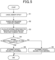
- step S1 the memory effect cancellation unit 81 cancels the memory effect in the secondary battery 2.
- the secondary battery is discharged until the battery voltage of the secondary battery 2 detected by the voltage value detection unit 42 and stored in the voltage value storage unit 52 is equal to or lower than 1.0 V.
- step S2 illustrated in Fig. 5 the constant current application unit 82 applies a constant current to the secondary battery 2 to charge and discharge the secondary battery 2.
- step S3 illustrated in Fig. 5 the internal resistance R in the negative-electrode reaction resistance dominant region of the secondary battery 2 is calculated.
- the current value detection unit 41 detects and stores the current value of the secondary battery 2 in the current value storage unit 51
- the voltage value detection unit 42 detects and stores the voltage value of the secondary battery 2 in the voltage value storage unit 52.
- the internal-resistance calculation unit 71 calculates the internal resistance R from the current value stored in the current value storage unit 51 and the voltage value stored in the voltage value storage unit 52.
- the internal resistance R calculated by the internal-resistance calculation unit 71 is stored in a resistance value storage unit not illustrated.
- step S4 illustrated in Fig. 5 the capacity balance comparison unit 72 compares the internal resistance R of the secondary battery 2 with the capacity balance threshold R1.
- the capacity balance threshold R1 is extracted from the threshold memory unit 61.
- the process proceeds to Yes in step S4, and in step S5, the abnormality determination unit 73 determines the capacity balance of the secondary battery 2 to be abnormal, and the process is terminated.
- step S6 the abnormality determination unit 73 determines the capacity balance in the secondary battery 2 to be normal, and the process is terminated.
- the capacity balance comparison unit 72 compares the internal resistance R in the negative-electrode reaction resistance dominant region calculated by the internal-resistance calculation unit 71 with the capacity balance threshold R1 stored in the threshold memory unit 61, and based on the comparison result, the abnormality determination unit 73 determines abnormality in capacity balance in the secondary battery 2. Accordingly, the abnormality determination device 1 determines abnormality in capacity balance based on the internal resistance R in the negative-electrode reaction resistance dominant region and thus enables abnormality in capacity balance to be determined in a shorter time than based on detection of complex impedances.
- the abnormality determination device 1 does not require expensive components for detecting complex impedances and can be relatively simply configured, enabling a reduction in costs.
- the abnormality determination unit 73 determines the capacity balance to be abnormal when the comparison result from the capacity balance comparison unit 72 indicates that the internal resistance R calculated by the internal-resistance calculation unit 71 is larger than the capacity balance threshold R1 stored in the threshold memory unit 61. This allows abnormality in capacity balance to be accurately determined in a shorter time based on the internal resistance R in the negative-electrode reaction resistance dominant region.
- the present embodiment includes the constant current application unit 82 applying a pulse current to the secondary battery 2 to charge and discharge the secondary battery 2, the current value detection unit 41 detecting the current value of the secondary battery 2, and the voltage value detection unit 42 detecting the voltage value of the secondary battery 2, and the internal-resistance calculation unit 71 calculates the internal resistance R in the negative-electrode reaction resistance dominant region based on the current value detected by the current value detection unit 41 and the voltage value detected by the voltage value detection unit 42. This allows abnormality to be accurately determined in a much shorter time than based on detection of complex impedances.
- the memory effect cancellation unit 81 cancels the memory effect in the secondary battery 2 before determining abnormality in capacity balance. This allows the memory effect to be eliminated from the secondary battery 2 before determination of abnormality in capacity balance, allowing the abnormality to be more accurately determined.
- the memory effect cancellation unit 81 cancels the memory effect in the secondary battery 2 before determination of abnormality in capacity balance
- the memory effect cancellation unit 81 may be omitted to avoid cancellation of the memory effect in the secondary battery 2.
- the abnormality determination device 1 for the secondary battery can be provided that has a simple configuration and that can inexpensively determine abnormality in a short time.
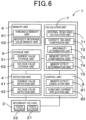
- An abnormality determination device 1 for the secondary battery includes, in addition to the components of the first embodiment illustrated in Fig. 1 , a necessity reference value memory unit 62 provided in the memory unit 6 and a memory effect comparison unit 74 and a memory effect determination unit 75 provided in the calculation unit 7 as illustrated in Fig. 6 .
- the other components of the present embodiment are equivalent to those of the first embodiment, and are denoted by the same reference signs in the first embodiment and will not be described below.
- the necessity reference value memory unit 62 illustrated in Fig. 1 stores a necessity reference value used as a reference for determining whether to cancel the memory effect in the secondary battery 2.
- the necessity reference value is information representing the resistance of the negative electrode 21 used as the reference.
- the necessity reference value is not limited to a particular form but can be in the form of a mathematical formula, a map, a table, or the like.
- the necessity reference value memory can be created based on measured values obtained by conducting an accelerated deterioration test on the secondary battery 2 for measurement, which is then disassembled for investigation, or can be created by a mathematical formula that logically derives production of the memory effect using a model of the secondary battery 2.
- the necessity reference value memory unit 62 may memorize a plurality of necessity reference values.
- the memory effect comparison unit 74 illustrated in Fig. 1 compares the internal resistance R calculated by the internal-resistance calculation unit 71 with a necessity reference value R2 stored in the necessity reference value memory unit 62.
- the memory effect determination unit 75 determines whether to cancel the memory effect in the secondary battery 2 based on a comparison result from the memory effect comparison unit 74.
- the memory effect determination unit 75 determines that the memory effect in the secondary battery 2 needs to be cancelled when the comparison result from the memory effect comparison unit 74 indicates that the internal resistance R calculated by the internal-resistance calculation unit 71 is smaller than the necessity reference value R2 stored in the necessity reference value memory unit 62.
- the negative electrode SOC exhibits a relatively high value even in a low SOC region of the secondary battery 2.
- Fig. 7(a) and Fig. 7(b) which corresponds to an enlarged view of a region P in Fig. 7(a) , with the negative electrode SOC having a relatively large value, the negative electrode resistance has a relatively small value.
- the negative electrode SOC is relatively high, allowing for a determination that the memory is present.
- the necessity reference value R2 is smaller than the capacity balance threshold R1.
- the memory effect cancellation unit 81 cancels the memory effect before the detection of the internal resistance R by the internal-resistance calculation unit 71 and also cancels the memory effect based on a determination result from the memory effect determination unit 75. Note that, after the memory effect cancellation unit 81 cancels the memory effect, the memory effect determination unit 75 may determine again whether to cancel the memory effect in the secondary battery 2.
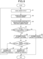
- step S7 the memory effect comparison unit 74 compares the internal resistance R with the necessity reference value R2 stored in the necessity reference value memory unit 62. Then, in step S7, in a case where the comparison result from the memory effect comparison unit 74 indicates that the internal resistance R is smaller than the necessity reference value R2, the process proceeds to Yes in step S7 illustrated in Fig. 8 .
- step S8 the memory effect determination unit 75 again determines that the memory effect needs to be cancelled, and the process returns to step S1 again.
- the process proceeds to No in step S7 illustrated in Fig. 8 .
- step S9 the memory effect determination unit 75 determines that the memory effect need not be cancelled, and the process is terminated.
- the present embodiment includes the necessity reference value memory unit 62 storing the necessity reference value R2 used as a reference for determining whether to cancel the memory effect, the memory effect comparison unit 74 comparing the internal resistance R calculated by the internal-resistance calculation unit 71 with the necessity reference value R2 stored in the necessity reference value memory unit 62, the memory effect determination unit 75 determining whether to cancel the memory effect in the secondary battery 2 based on the comparison result from the memory effect comparison unit 74, and the memory effect cancellation unit 81 cancelling the memory effect in the secondary battery 2.
- the memory effect cancellation unit 81 cancels the memory effect of the secondary battery 2 before the abnormality determination unit 73 determines abnormality. Accordingly, in a case where the memory is present in the secondary battery 2, the memory effect can be cancelled before abnormality in capacity balance is determined, allowing abnormality in capacity balance to be accurately determined.
- the memory effect determination unit 75 determines that the memory effect in the secondary battery 2 needs to be canceled when the comparison result from the memory effect comparison unit 74 indicates that the internal resistance R calculated by the internal-resistance calculation unit 71 is smaller than the necessity reference value R2 stored in the necessity reference value memory unit 62. This allows accurate detection of whether the memory is present.
- the memory effect determination unit 75 is configured to determine again whether to cancel the memory effect in the secondary battery 2 after the memory effect cancellation unit 81 cancels the memory effect. Accordingly, for example, in a case where the memory effect in the secondary battery 2 has been insufficiently cancelled, the memory effect is cancelled again to allow abnormality in capacity balance to be accurately determined.
- the memory effect cancellation unit 81 is configured to discharge the secondary battery 2 until the battery voltage of the secondary battery 2 is equal to or lower than a predetermined value to cancel the memory effect. This allows the memory effect of the secondary battery 2 to be reliably cancelled, contributing to an increased accuracy of determination of abnormality in capacity balance.
- step S8 the memory effect determination unit 75 determines in step S81 whether the last determination is the necessity for cancellation of the memory effect, as in a first modification illustrated in Fig. 9 .
- the process proceeds to Yes in step S81, and in step S82, the memory effect determination unit 75 determines cancellation of the memory effect in the secondary battery 2 to be abnormal, and ends the control flow.
- step S8 the process proceeds to step S8, and returns to step S1 illustrated in Fig. 8 .
- the control flow can be ended and prevented from being unnecessarily repeated.
- step S81 determines whether the last determination is the necessity for cancellation of the memory effect but that no such limitation is intended and that whether cancellation of the memory effect has been determined to be necessary a predetermined number of times before.
- An abnormality determination device 1 for the secondary battery includes, in addition to the components of the first embodiment illustrated in Fig. 1 , a threshold correction unit 76 provided in the calculation unit 7 and correcting the capacity balance threshold stored in the threshold memory unit 61 based on a temperature detected by a temperature detection unit 43, as illustrated in Fig. 10 . Additionally, the detection unit 4 includes the temperature detection unit 43 detecting the temperature of the secondary battery 2, and the storage unit 5 includes a temperature storage unit 53 storing the temperature detected by the temperature detection unit 43.
- the other components of the present embodiment are equivalent to those of the first embodiment, and are denoted by the same reference signs in the first embodiment and will not be described below.
- the threshold correction unit 76 illustrated in Fig. 7 calculates a corrected capacity balance threshold R1' by correcting the capacity balance threshold R1 stored in the threshold memory unit 61 based on the temperature detected by the temperature detection unit 43.
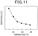
- the threshold correction unit 76 can acquire a correspondence relationship between the internal resistance R and the temperature in advance, and calculates the corrected capacity balance threshold R1' by correcting, based on the correspondence relationship and the temperature detected by the temperature detection unit 43, the capacity balance threshold R1 stored in the threshold memory unit 61.
- the present embodiment as illustrated in Fig.
- a correspondence relationship between the reaction resistance and temperature of the negative electrode 21 is acquired and stored in a memory unit not illustrated, in advance, and the threshold correction unit 76 calculates the corrected capacity balance threshold R1' by correcting the capacity balance threshold R1 based on the correspondence relationship and the temperature detected by the temperature detection unit 43.
- step S4 the threshold correction unit 76 calculates the corrected capacity balance threshold R1' by correcting, based on the temperature detected by the temperature detection unit 43, the capacity balance threshold R1 stored in the threshold memory unit 61.
- step S41 the internal resistance R is compared with the corrected capacity balance threshold R1'.
- step S4 the abnormality determination unit 73 determines the capacity balance in the secondary battery 2 to be abnormal, and the process is terminated.
- step S6 the abnormality determination unit 73 determines that the capacity balance in the secondary battery 2 to be normal, and the process is terminated.
- the abnormality determination device 1 includes the temperature detection unit 43 detecting the temperature of the secondary battery 2, and the threshold correction unit 76 computing the corrected capacity balance threshold R1' by correcting, based on the temperature detected by the temperature detection unit 43, the capacity balance threshold R1 stored in the threshold memory unit 61, and the capacity balance comparison unit 72 compares the corrected capacity balance threshold R1' with the internal resistance R.
- the present embodiment since the internal resistance R varies depending on temperature, abnormality in capacity balance can be more accurately determined by determining abnormality using the corrected capacity balance threshold R1' resulting from correction based on the temperature of the secondary battery 2. Note that the present embodiment achieves functions and effects equivalent to those of the first embodiment.
- the present disclosure is not limited to the above-described embodiments.
- the configuration including the necessity reference value memory unit 62, the memory effect comparison unit 74, and the memory effect determination unit 75 according to the second embodiment may be combined with the configuration including the threshold correction unit 76 according to the third embodiment.
Landscapes
- Physics & Mathematics (AREA)
- General Physics & Mathematics (AREA)
- Engineering & Computer Science (AREA)
- Manufacturing & Machinery (AREA)
- Chemical & Material Sciences (AREA)
- Chemical Kinetics & Catalysis (AREA)
- Electrochemistry (AREA)
- General Chemical & Material Sciences (AREA)
- Power Engineering (AREA)
- Secondary Cells (AREA)
- Tests Of Electric Status Of Batteries (AREA)
- Charge And Discharge Circuits For Batteries Or The Like (AREA)
Claims (8)
- Anomaliebestimmungsgerät (1) für eine Sekundärbatterie (2), wobei das Anomaliebestimmungsgerät aufweist:eine Innenwiderstandsberechnungseinheit (71), die dazu eingerichtet ist, um einen Innenwiderstand (R) in einem Negativelektrodenreaktionswiderstandsdominanzbereich, in dem ein Reaktionswiderstand einer Negativelektrode (21) dominant in einer Lade- und Entladereaktion der Sekundärbatterie ist, zu berechnen,eine Schwellenspeichereinheit (61), die eine als eine Referenz für eine Bestimmung, ob eine Balance zwischen einer Kapazität einer Positivelektrode und einer Kapazität der Negativelektrode in der Sekundärbatterie anormal ist, verwendete Kapazitätsbalanceschwelle (R1) speichert,eine Kapazitätsbalancevergleichseinheit (72), die dazu eingerichtet ist, um den durch die Innenwiderstandsberechnungseinheit erfassten Innenwiderstand mit der in der Schwellenspeichereinheit gespeicherten Kapazitätsbalanceschwelle zu vergleichen, undeine Anomaliebestimmungseinheit (73), die dazu eingerichtet ist, um eine Anomalie in einer Kapazitätsbalance in der Sekundärbatterie basierend auf einem Vergleichsergebnis von der Kapazitätsbalancevergleichseinheit zu bestimmen.
- Anomaliebestimmungsgerät für die Sekundärbatterie nach Anspruch 1, wobei
die Anomaliebestimmungseinheit die Kapazitätsbalance als anormal bestimmt, wenn ein Vergleichsergebnis von der Kapazitätsbalancevergleichseinheit angibt, dass der durch die Innenwiderstandsberechnungseinheit berechnete Innenwiderstand größer als die in der Schwellenspeichereinheit gespeicherte Kapazitätsbalanceschwelle ist. - Anomaliebestimmungsgerät für die Sekundärbatterie nach Anspruch 1 oder 2, wobei das Anomaliebestimmungsgerät ferner aufweist:eine Konstantstrombeaufschlageinheit (82), die dazu eingerichtet ist, um einen Pulsstrom auf die Sekundärbatterie zu beaufschlagen, um die Sekundärbatterie zu laden und zu entladen,eine Stromwerterfassungseinheit (41), die dazu eingerichtet ist, um einen Stromwert in der Sekundärbatterie zu erfassen, undeine Spannungswerterfassungseinheit (42), die dazu eingerichtet ist, um einen Spannungswert in der Sekundärbatterie zu erfassen, wobeidie Innenwiderstandsberechnungseinheit den Innenwiderstand in dem Negativelektrodenreaktionswiderstandsdominanzbereich basierend auf dem durch die Stromwerterfassungseinheit erfassten Stromwert und dem durch die Spannungswerterfassungseinheit erfassten Spannungswert berechnet.
- Anomaliebestimmungsgerät für die Sekundärbatterie nach einem der Ansprüche 1 bis 3, wobei das Anomaliebestimmungsgerät ferner aufweist:eine Notwendigkeitsreferenzwertspeichereinheit (62), die einen Notwendigkeitsreferenzwert entsprechend einer Referenz für eine Bestimmung, ob ein Memory-Effekt zu beheben ist, speichert,eine Memory-Effekt-Vergleichseinheit (74), die dazu eingerichtet ist, um den durch die Innenwiderstandsberechnungseinheit berechneten Innenwiderstand mit dem in der Notwendigkeitsreferenzwertspeichereinheit gespeicherten Notwendigkeitsreferenzwert zu vergleichen,eine Memory-Effekt-Bestimmungseinheit (75), die dazu eingerichtet ist, um basierend auf einem Vergleichsergebnis von der Memory-Effekt-Vergleichseinheit zu bestimmen, ob der Memory-Effekt in der Sekundärbatterie zu beheben ist, undeine Memory-Effekt-Behebeinheit (81), die dazu eingerichtet ist, um den Memory-Effekt in der Sekundärbatterie zu beheben, wobeials Reaktion darauf, dass die Memory-Effekt-Bestimmungseinheit bestimmt, dass der Memory-Effekt behoben werden muss, die Memory-Effekt-Behebeinheit den Memory-Effekt in der Sekundärbatterie behebt, bevor die Anomaliebestimmungseinheit die Anomalie bestimmt.
- Anomaliebestimmungsgerät für die Sekundärbatterie nach Anspruch 4, wobei
die Memory-Effekt-Bestimmungseinheit bestimmt, dass der Memory-Effekt in der Sekundärbatterie behoben werden muss, wenn das Vergleichsergebnis von der Memory-Effekt-Vergleichseinheit angibt, dass der durch die Innenwiderstandsberechnungseinheit berechnete Innenwiderstand kleiner als der in der Notwendigkeitsreferenzwertspeichereinheit gespeicherte Notwendigkeitsreferenzwert ist. - Anomaliebestimmungsgerät für die Sekundärbatterie nach Anspruch 4 oder 5, wobei
die Memory-Effekt-Bestimmungseinheit dazu eingerichtet ist, um erneut zu bestimmen, ob der Memory-Effekt in der Sekundärbatterie zu beheben ist, nachdem die Memory-Effekt-Behebeinheit den Memory-Effekt behebt. - Anomaliebestimmungsgerät für die Sekundärbatterie nach einem der Ansprüche 4 bis 6, wobei
die Memory-Effekt-Behebeinheit dazu eingerichtet ist, um die Sekundärbatterie zu entladen, um den Memory-Effekt zu beheben, bis eine Batteriespannung der Sekundärbatterie gleich wie oder geringer als ein vorbestimmter Wert ist. - Anomaliebestimmungsgerät für die Sekundärbatterie nach einem der Ansprüche 1 bis 7, wobei das Anomaliebestimmungsgerät ferner aufweist:eine Temperaturerfassungseinheit (43) dazu eingerichtet ist, um eine Temperatur der Sekundärbatterie zu erfassen, undeine Schwellenkorrektureinheit (76), die dazu eingerichtet ist, um eine korrigierte Kapazitätsbalanceschwelle (R1') durch Korrektur der in der Schwellenspeichereinheit gespeicherten Kapazitätsbalanceschwelle basierend auf der durch die Temperaturerfassungseinheit erfassten Temperatur zu berechnen, wobeidie Kapazitätsbalancevergleichseinheit den Innenwiderstand mit der korrigierten Kapazitätsbalanceschwelle vergleicht.
Applications Claiming Priority (2)
| Application Number | Priority Date | Filing Date | Title |
|---|---|---|---|
| JP2018024388A JP6958412B2 (ja) | 2018-02-14 | 2018-02-14 | 二次電池の異常判定装置 |
| PCT/JP2019/001009 WO2019159584A1 (ja) | 2018-02-14 | 2019-01-16 | 二次電池の異常判定装置 |
Publications (3)
| Publication Number | Publication Date |
|---|---|
| EP3754351A1 EP3754351A1 (de) | 2020-12-23 |
| EP3754351A4 EP3754351A4 (de) | 2021-04-07 |
| EP3754351B1 true EP3754351B1 (de) | 2023-11-01 |
Family
ID=67619396
Family Applications (1)
| Application Number | Title | Priority Date | Filing Date |
|---|---|---|---|
| EP19755245.8A Active EP3754351B1 (de) | 2018-02-14 | 2019-01-16 | Vorrichtung zur bestimmung von anomalien bei einer sekundärbatterie |
Country Status (6)
| Country | Link |
|---|---|
| US (1) | US11340277B2 (de) |
| EP (1) | EP3754351B1 (de) |
| JP (1) | JP6958412B2 (de) |
| CN (1) | CN111712715B (de) |
| ES (1) | ES2971607T3 (de) |
| WO (1) | WO2019159584A1 (de) |
Families Citing this family (6)
| Publication number | Priority date | Publication date | Assignee | Title |
|---|---|---|---|---|
| CN112736302B (zh) * | 2020-12-24 | 2021-12-07 | 广州橙行智动汽车科技有限公司 | 一种电芯容量异常判断方法及装置、车辆、存储介质 |
| JP7540403B2 (ja) | 2021-06-29 | 2024-08-27 | 株式会社デンソー | 電池測定装置及び電池測定方法 |
| CN114441968B (zh) * | 2021-12-02 | 2025-07-04 | 北京车和家汽车科技有限公司 | 电池自放电的监控方法、装置、计算机设备及存储介质 |
| JP7775720B2 (ja) * | 2022-01-20 | 2025-11-26 | 株式会社デンソー | 二次電池システム |
| WO2024050798A1 (zh) * | 2022-09-09 | 2024-03-14 | 宁德时代新能源科技股份有限公司 | 记忆效应消除方法、装置、计算机设备及存储介质 |
| CN120722237B (zh) * | 2025-08-29 | 2025-10-31 | 深圳市瑞能实业股份有限公司 | 一种电池的接触阻抗及温度的检测系统及检测设备 |
Family Cites Families (16)
| Publication number | Priority date | Publication date | Assignee | Title |
|---|---|---|---|---|
| JP4110639B2 (ja) * | 1998-11-04 | 2008-07-02 | 株式会社デンソー | 電池の残存容量演算装置 |
| JP2002042895A (ja) * | 2000-07-19 | 2002-02-08 | Honda Motor Co Ltd | バッテリの状態検出装置 |
| JP3706565B2 (ja) * | 2001-09-20 | 2005-10-12 | 三洋電機株式会社 | ハイブリッドカー用の電源装置 |
| JP4043977B2 (ja) * | 2003-03-11 | 2008-02-06 | 株式会社日本自動車部品総合研究所 | 二次電池の内部抵抗検出装置および内部抵抗検出方法 |
| JP2005065352A (ja) * | 2003-08-11 | 2005-03-10 | Nissan Motor Co Ltd | バッテリ充放電制御装置 |
| JP4038456B2 (ja) | 2003-08-25 | 2008-01-23 | 株式会社豊田中央研究所 | 電池特性検出方法 |
| JP2008041565A (ja) | 2006-08-09 | 2008-02-21 | Toyota Central Res & Dev Lab Inc | 電池特性の検出方法及び検出装置 |
| WO2008026476A1 (en) * | 2006-08-29 | 2008-03-06 | Nec Corporation | Method and device for estimating soc value of secondary battery and degradation judging method and device |
| JP5656415B2 (ja) * | 2009-03-26 | 2015-01-21 | プライムアースEvエナジー株式会社 | 二次電池の状態判定装置及び制御装置 |
| JP5624333B2 (ja) * | 2009-03-31 | 2014-11-12 | プライムアースEvエナジー株式会社 | 二次電池の制御装置及びマップの補正方法 |
| JP5682955B2 (ja) * | 2010-08-04 | 2015-03-11 | Necエナジーデバイス株式会社 | リチウム二次電池の制御システム、およびリチウム二次電池の状態検出方法 |
| WO2013115038A1 (ja) | 2012-01-31 | 2013-08-08 | プライムアースEvエナジー株式会社 | 電池状態検出装置 |
| JP6123844B2 (ja) * | 2014-09-01 | 2017-05-10 | 横河電機株式会社 | 二次電池容量測定システム及び二次電池容量測定方法 |
| CN104391159B (zh) * | 2014-10-27 | 2017-06-06 | 清华大学 | 电池的单电极电位的检测方法及系统 |
| JP6114321B2 (ja) | 2015-02-17 | 2017-04-12 | プライムアースEvエナジー株式会社 | 車両用の二次電池の再利用方法 |
| JP6662228B2 (ja) * | 2016-07-20 | 2020-03-11 | トヨタ自動車株式会社 | 電池システム |
-
2018
- 2018-02-14 JP JP2018024388A patent/JP6958412B2/ja active Active
-
2019
- 2019-01-16 EP EP19755245.8A patent/EP3754351B1/de active Active
- 2019-01-16 ES ES19755245T patent/ES2971607T3/es active Active
- 2019-01-16 WO PCT/JP2019/001009 patent/WO2019159584A1/ja not_active Ceased
- 2019-01-16 CN CN201980013204.XA patent/CN111712715B/zh active Active
-
2020
- 2020-08-13 US US16/992,578 patent/US11340277B2/en active Active
Also Published As
| Publication number | Publication date |
|---|---|
| JP2019138852A (ja) | 2019-08-22 |
| EP3754351A1 (de) | 2020-12-23 |
| US11340277B2 (en) | 2022-05-24 |
| EP3754351A4 (de) | 2021-04-07 |
| US20200371145A1 (en) | 2020-11-26 |
| WO2019159584A1 (ja) | 2019-08-22 |
| CN111712715A (zh) | 2020-09-25 |
| ES2971607T3 (es) | 2024-06-06 |
| CN111712715B (zh) | 2023-02-21 |
| JP6958412B2 (ja) | 2021-11-02 |
Similar Documents
| Publication | Publication Date | Title |
|---|---|---|
| EP3754351B1 (de) | Vorrichtung zur bestimmung von anomalien bei einer sekundärbatterie | |
| KR102848878B1 (ko) | 이차 전지 진단 장치 및 방법 | |
| US20230204674A1 (en) | Method and device for determining available capacity of battery, management system, and storage medium | |
| US10989761B2 (en) | Method for estimating the state of health of a battery | |
| US9263773B2 (en) | Secondary battery state of charge determination apparatus, and method of determining state of charge of secondary battery | |
| US11221370B2 (en) | Remaining battery energy estimation device, remaining battery energy estimation method, and storage medium | |
| US10845417B2 (en) | Battery state estimation device, battery control device, battery system, battery state estimation method | |
| EP2711727B1 (de) | Batterie-Zustandsschätzungsvorrichtung und Verfahren zur Erzeugung einer Charakteristik der Leerlaufspannung | |
| KR102206606B1 (ko) | 배터리 여유 용량 추정 장치 | |
| US20180299511A1 (en) | Apparatus for estimating battery degradation state, system including the same, and method thereof | |
| US20140055100A1 (en) | Battery state estimation system, battery control system, battery system, and battery state estimation method | |
| JP2017122622A (ja) | 状態推定装置、状態推定方法 | |
| EP2725371A2 (de) | Vorrichtung zur Erkennung des elektrischen Ladezustands | |
| US20140365150A1 (en) | Method and device for determining a charge state of an electric energy store | |
| US10578675B2 (en) | Estimation method for battery capacity | |
| US20230198035A1 (en) | Measurement apparatus, and measurement method | |
| CN112394290B (zh) | 电池包soh的估算方法、装置、计算机设备和存储介质 | |
| JP7705756B2 (ja) | 電池状態推定方法及び電池状態推定装置 | |
| JP6657778B2 (ja) | Soc推定装置 | |
| JP2010060381A (ja) | 電池状態測定装置および電池状態測定方法 | |
| JP2025151587A (ja) | リチウムイオンキャパシタの劣化判定装置 | |
| JP2024050293A (ja) | 半導体装置、電池監視方法、及び電池監視システム |
Legal Events
| Date | Code | Title | Description |
|---|---|---|---|
| STAA | Information on the status of an ep patent application or granted ep patent |
Free format text: STATUS: THE INTERNATIONAL PUBLICATION HAS BEEN MADE |
|
| PUAI | Public reference made under article 153(3) epc to a published international application that has entered the european phase |
Free format text: ORIGINAL CODE: 0009012 |
|
| STAA | Information on the status of an ep patent application or granted ep patent |
Free format text: STATUS: REQUEST FOR EXAMINATION WAS MADE |
|
| 17P | Request for examination filed |
Effective date: 20200825 |
|
| AK | Designated contracting states |
Kind code of ref document: A1 Designated state(s): AL AT BE BG CH CY CZ DE DK EE ES FI FR GB GR HR HU IE IS IT LI LT LU LV MC MK MT NL NO PL PT RO RS SE SI SK SM TR |
|
| AX | Request for extension of the european patent |
Extension state: BA ME |
|
| STAA | Information on the status of an ep patent application or granted ep patent |
Free format text: STATUS: EXAMINATION IS IN PROGRESS |
|
| A4 | Supplementary search report drawn up and despatched |
Effective date: 20210310 |
|
| RIC1 | Information provided on ipc code assigned before grant |
Ipc: H02J 7/00 20060101ALI20210303BHEP Ipc: G01R 31/36 20200101AFI20210303BHEP Ipc: H01M 10/42 20060101ALI20210303BHEP Ipc: G01R 31/389 20190101ALI20210303BHEP Ipc: H01M 10/48 20060101ALI20210303BHEP Ipc: H01M 10/44 20060101ALI20210303BHEP Ipc: G01R 31/392 20190101ALI20210303BHEP |
|
| 17Q | First examination report despatched |
Effective date: 20210322 |
|
| DAV | Request for validation of the european patent (deleted) | ||
| DAX | Request for extension of the european patent (deleted) | ||
| GRAP | Despatch of communication of intention to grant a patent |
Free format text: ORIGINAL CODE: EPIDOSNIGR1 |
|
| STAA | Information on the status of an ep patent application or granted ep patent |
Free format text: STATUS: GRANT OF PATENT IS INTENDED |
|
| INTG | Intention to grant announced |
Effective date: 20230512 |
|
| GRAS | Grant fee paid |
Free format text: ORIGINAL CODE: EPIDOSNIGR3 |
|
| GRAA | (expected) grant |
Free format text: ORIGINAL CODE: 0009210 |
|
| STAA | Information on the status of an ep patent application or granted ep patent |
Free format text: STATUS: THE PATENT HAS BEEN GRANTED |
|
| AK | Designated contracting states |
Kind code of ref document: B1 Designated state(s): AL AT BE BG CH CY CZ DE DK EE ES FI FR GB GR HR HU IE IS IT LI LT LU LV MC MK MT NL NO PL PT RO RS SE SI SK SM TR |
|
| REG | Reference to a national code |
Ref country code: GB Ref legal event code: FG4D |
|
| REG | Reference to a national code |
Ref country code: CH Ref legal event code: EP |
|
| REG | Reference to a national code |
Ref country code: IE Ref legal event code: FG4D |
|
| REG | Reference to a national code |
Ref country code: DE Ref legal event code: R096 Ref document number: 602019040594 Country of ref document: DE |
|
| REG | Reference to a national code |
Ref country code: LT Ref legal event code: MG9D |
|
| REG | Reference to a national code |
Ref country code: NL Ref legal event code: MP Effective date: 20231101 |
|
| PG25 | Lapsed in a contracting state [announced via postgrant information from national office to epo] |
Ref country code: GR Free format text: LAPSE BECAUSE OF FAILURE TO SUBMIT A TRANSLATION OF THE DESCRIPTION OR TO PAY THE FEE WITHIN THE PRESCRIBED TIME-LIMIT Effective date: 20240202 |
|
| PG25 | Lapsed in a contracting state [announced via postgrant information from national office to epo] |
Ref country code: IS Free format text: LAPSE BECAUSE OF FAILURE TO SUBMIT A TRANSLATION OF THE DESCRIPTION OR TO PAY THE FEE WITHIN THE PRESCRIBED TIME-LIMIT Effective date: 20240301 |
|
| PG25 | Lapsed in a contracting state [announced via postgrant information from national office to epo] |
Ref country code: LT Free format text: LAPSE BECAUSE OF FAILURE TO SUBMIT A TRANSLATION OF THE DESCRIPTION OR TO PAY THE FEE WITHIN THE PRESCRIBED TIME-LIMIT Effective date: 20231101 |
|
| REG | Reference to a national code |
Ref country code: AT Ref legal event code: MK05 Ref document number: 1627804 Country of ref document: AT Kind code of ref document: T Effective date: 20231101 |
|
| PG25 | Lapsed in a contracting state [announced via postgrant information from national office to epo] |
Ref country code: NL Free format text: LAPSE BECAUSE OF FAILURE TO SUBMIT A TRANSLATION OF THE DESCRIPTION OR TO PAY THE FEE WITHIN THE PRESCRIBED TIME-LIMIT Effective date: 20231101 |
|
| PG25 | Lapsed in a contracting state [announced via postgrant information from national office to epo] |
Ref country code: AT Free format text: LAPSE BECAUSE OF FAILURE TO SUBMIT A TRANSLATION OF THE DESCRIPTION OR TO PAY THE FEE WITHIN THE PRESCRIBED TIME-LIMIT Effective date: 20231101 |
|
| PG25 | Lapsed in a contracting state [announced via postgrant information from national office to epo] |
Ref country code: NL Free format text: LAPSE BECAUSE OF FAILURE TO SUBMIT A TRANSLATION OF THE DESCRIPTION OR TO PAY THE FEE WITHIN THE PRESCRIBED TIME-LIMIT Effective date: 20231101 Ref country code: LT Free format text: LAPSE BECAUSE OF FAILURE TO SUBMIT A TRANSLATION OF THE DESCRIPTION OR TO PAY THE FEE WITHIN THE PRESCRIBED TIME-LIMIT Effective date: 20231101 Ref country code: IS Free format text: LAPSE BECAUSE OF FAILURE TO SUBMIT A TRANSLATION OF THE DESCRIPTION OR TO PAY THE FEE WITHIN THE PRESCRIBED TIME-LIMIT Effective date: 20240301 Ref country code: GR Free format text: LAPSE BECAUSE OF FAILURE TO SUBMIT A TRANSLATION OF THE DESCRIPTION OR TO PAY THE FEE WITHIN THE PRESCRIBED TIME-LIMIT Effective date: 20240202 Ref country code: BG Free format text: LAPSE BECAUSE OF FAILURE TO SUBMIT A TRANSLATION OF THE DESCRIPTION OR TO PAY THE FEE WITHIN THE PRESCRIBED TIME-LIMIT Effective date: 20240201 Ref country code: AT Free format text: LAPSE BECAUSE OF FAILURE TO SUBMIT A TRANSLATION OF THE DESCRIPTION OR TO PAY THE FEE WITHIN THE PRESCRIBED TIME-LIMIT Effective date: 20231101 Ref country code: PT Free format text: LAPSE BECAUSE OF FAILURE TO SUBMIT A TRANSLATION OF THE DESCRIPTION OR TO PAY THE FEE WITHIN THE PRESCRIBED TIME-LIMIT Effective date: 20240301 |
|
| PG25 | Lapsed in a contracting state [announced via postgrant information from national office to epo] |
Ref country code: SE Free format text: LAPSE BECAUSE OF FAILURE TO SUBMIT A TRANSLATION OF THE DESCRIPTION OR TO PAY THE FEE WITHIN THE PRESCRIBED TIME-LIMIT Effective date: 20231101 Ref country code: RS Free format text: LAPSE BECAUSE OF FAILURE TO SUBMIT A TRANSLATION OF THE DESCRIPTION OR TO PAY THE FEE WITHIN THE PRESCRIBED TIME-LIMIT Effective date: 20231101 Ref country code: PL Free format text: LAPSE BECAUSE OF FAILURE TO SUBMIT A TRANSLATION OF THE DESCRIPTION OR TO PAY THE FEE WITHIN THE PRESCRIBED TIME-LIMIT Effective date: 20231101 Ref country code: NO Free format text: LAPSE BECAUSE OF FAILURE TO SUBMIT A TRANSLATION OF THE DESCRIPTION OR TO PAY THE FEE WITHIN THE PRESCRIBED TIME-LIMIT Effective date: 20240201 Ref country code: LV Free format text: LAPSE BECAUSE OF FAILURE TO SUBMIT A TRANSLATION OF THE DESCRIPTION OR TO PAY THE FEE WITHIN THE PRESCRIBED TIME-LIMIT Effective date: 20231101 Ref country code: HR Free format text: LAPSE BECAUSE OF FAILURE TO SUBMIT A TRANSLATION OF THE DESCRIPTION OR TO PAY THE FEE WITHIN THE PRESCRIBED TIME-LIMIT Effective date: 20231101 |
|
| REG | Reference to a national code |
Ref country code: ES Ref legal event code: FG2A Ref document number: 2971607 Country of ref document: ES Kind code of ref document: T3 Effective date: 20240606 |
|
| PG25 | Lapsed in a contracting state [announced via postgrant information from national office to epo] |
Ref country code: DK Free format text: LAPSE BECAUSE OF FAILURE TO SUBMIT A TRANSLATION OF THE DESCRIPTION OR TO PAY THE FEE WITHIN THE PRESCRIBED TIME-LIMIT Effective date: 20231101 |
|
| PG25 | Lapsed in a contracting state [announced via postgrant information from national office to epo] |
Ref country code: CZ Free format text: LAPSE BECAUSE OF FAILURE TO SUBMIT A TRANSLATION OF THE DESCRIPTION OR TO PAY THE FEE WITHIN THE PRESCRIBED TIME-LIMIT Effective date: 20231101 |
|
| PG25 | Lapsed in a contracting state [announced via postgrant information from national office to epo] |
Ref country code: SK Free format text: LAPSE BECAUSE OF FAILURE TO SUBMIT A TRANSLATION OF THE DESCRIPTION OR TO PAY THE FEE WITHIN THE PRESCRIBED TIME-LIMIT Effective date: 20231101 |
|
| PG25 | Lapsed in a contracting state [announced via postgrant information from national office to epo] |
Ref country code: SM Free format text: LAPSE BECAUSE OF FAILURE TO SUBMIT A TRANSLATION OF THE DESCRIPTION OR TO PAY THE FEE WITHIN THE PRESCRIBED TIME-LIMIT Effective date: 20231101 Ref country code: SK Free format text: LAPSE BECAUSE OF FAILURE TO SUBMIT A TRANSLATION OF THE DESCRIPTION OR TO PAY THE FEE WITHIN THE PRESCRIBED TIME-LIMIT Effective date: 20231101 Ref country code: EE Free format text: LAPSE BECAUSE OF FAILURE TO SUBMIT A TRANSLATION OF THE DESCRIPTION OR TO PAY THE FEE WITHIN THE PRESCRIBED TIME-LIMIT Effective date: 20231101 Ref country code: DK Free format text: LAPSE BECAUSE OF FAILURE TO SUBMIT A TRANSLATION OF THE DESCRIPTION OR TO PAY THE FEE WITHIN THE PRESCRIBED TIME-LIMIT Effective date: 20231101 Ref country code: CZ Free format text: LAPSE BECAUSE OF FAILURE TO SUBMIT A TRANSLATION OF THE DESCRIPTION OR TO PAY THE FEE WITHIN THE PRESCRIBED TIME-LIMIT Effective date: 20231101 |
|
| REG | Reference to a national code |
Ref country code: DE Ref legal event code: R097 Ref document number: 602019040594 Country of ref document: DE |
|
| PG25 | Lapsed in a contracting state [announced via postgrant information from national office to epo] |
Ref country code: MC Free format text: LAPSE BECAUSE OF FAILURE TO SUBMIT A TRANSLATION OF THE DESCRIPTION OR TO PAY THE FEE WITHIN THE PRESCRIBED TIME-LIMIT Effective date: 20231101 |
|
| PG25 | Lapsed in a contracting state [announced via postgrant information from national office to epo] |
Ref country code: MC Free format text: LAPSE BECAUSE OF FAILURE TO SUBMIT A TRANSLATION OF THE DESCRIPTION OR TO PAY THE FEE WITHIN THE PRESCRIBED TIME-LIMIT Effective date: 20231101 |
|
| REG | Reference to a national code |
Ref country code: CH Ref legal event code: PL |
|
| PLBE | No opposition filed within time limit |
Free format text: ORIGINAL CODE: 0009261 |
|
| STAA | Information on the status of an ep patent application or granted ep patent |
Free format text: STATUS: NO OPPOSITION FILED WITHIN TIME LIMIT |
|
| PG25 | Lapsed in a contracting state [announced via postgrant information from national office to epo] |
Ref country code: LU Free format text: LAPSE BECAUSE OF NON-PAYMENT OF DUE FEES Effective date: 20240116 |
|
| PG25 | Lapsed in a contracting state [announced via postgrant information from national office to epo] |
Ref country code: LU Free format text: LAPSE BECAUSE OF NON-PAYMENT OF DUE FEES Effective date: 20240116 |
|
| 26N | No opposition filed |
Effective date: 20240802 |
|
| PG25 | Lapsed in a contracting state [announced via postgrant information from national office to epo] |
Ref country code: BE Free format text: LAPSE BECAUSE OF NON-PAYMENT OF DUE FEES Effective date: 20240131 |
|
| PG25 | Lapsed in a contracting state [announced via postgrant information from national office to epo] |
Ref country code: CH Free format text: LAPSE BECAUSE OF NON-PAYMENT OF DUE FEES Effective date: 20240131 |
|
| PG25 | Lapsed in a contracting state [announced via postgrant information from national office to epo] |
Ref country code: SI Free format text: LAPSE BECAUSE OF FAILURE TO SUBMIT A TRANSLATION OF THE DESCRIPTION OR TO PAY THE FEE WITHIN THE PRESCRIBED TIME-LIMIT Effective date: 20231101 |
|
| PG25 | Lapsed in a contracting state [announced via postgrant information from national office to epo] |
Ref country code: SI Free format text: LAPSE BECAUSE OF FAILURE TO SUBMIT A TRANSLATION OF THE DESCRIPTION OR TO PAY THE FEE WITHIN THE PRESCRIBED TIME-LIMIT Effective date: 20231101 Ref country code: CH Free format text: LAPSE BECAUSE OF NON-PAYMENT OF DUE FEES Effective date: 20240131 Ref country code: BE Free format text: LAPSE BECAUSE OF NON-PAYMENT OF DUE FEES Effective date: 20240131 |
|
| REG | Reference to a national code |
Ref country code: BE Ref legal event code: MM Effective date: 20240131 |
|
| PG25 | Lapsed in a contracting state [announced via postgrant information from national office to epo] |
Ref country code: IE Free format text: LAPSE BECAUSE OF NON-PAYMENT OF DUE FEES Effective date: 20240116 |
|
| PG25 | Lapsed in a contracting state [announced via postgrant information from national office to epo] |
Ref country code: IE Free format text: LAPSE BECAUSE OF NON-PAYMENT OF DUE FEES Effective date: 20240116 |
|
| PG25 | Lapsed in a contracting state [announced via postgrant information from national office to epo] |
Ref country code: RO Free format text: LAPSE BECAUSE OF FAILURE TO SUBMIT A TRANSLATION OF THE DESCRIPTION OR TO PAY THE FEE WITHIN THE PRESCRIBED TIME-LIMIT Effective date: 20231101 |
|
| PG25 | Lapsed in a contracting state [announced via postgrant information from national office to epo] |
Ref country code: CY Free format text: LAPSE BECAUSE OF FAILURE TO SUBMIT A TRANSLATION OF THE DESCRIPTION OR TO PAY THE FEE WITHIN THE PRESCRIBED TIME-LIMIT; INVALID AB INITIO Effective date: 20190116 |
|
| PG25 | Lapsed in a contracting state [announced via postgrant information from national office to epo] |
Ref country code: HU Free format text: LAPSE BECAUSE OF FAILURE TO SUBMIT A TRANSLATION OF THE DESCRIPTION OR TO PAY THE FEE WITHIN THE PRESCRIBED TIME-LIMIT; INVALID AB INITIO Effective date: 20190116 |
|
| PG25 | Lapsed in a contracting state [announced via postgrant information from national office to epo] |
Ref country code: FI Free format text: LAPSE BECAUSE OF FAILURE TO SUBMIT A TRANSLATION OF THE DESCRIPTION OR TO PAY THE FEE WITHIN THE PRESCRIBED TIME-LIMIT Effective date: 20231101 |
|
| PG25 | Lapsed in a contracting state [announced via postgrant information from national office to epo] |
Ref country code: TR Free format text: LAPSE BECAUSE OF FAILURE TO SUBMIT A TRANSLATION OF THE DESCRIPTION OR TO PAY THE FEE WITHIN THE PRESCRIBED TIME-LIMIT Effective date: 20231101 |
|
| PGFP | Annual fee paid to national office [announced via postgrant information from national office to epo] |
Ref country code: GB Payment date: 20260123 Year of fee payment: 8 |
|
| PGFP | Annual fee paid to national office [announced via postgrant information from national office to epo] |
Ref country code: ES Payment date: 20260227 Year of fee payment: 8 |
|
| PGFP | Annual fee paid to national office [announced via postgrant information from national office to epo] |
Ref country code: DE Payment date: 20260121 Year of fee payment: 8 |
|
| PGFP | Annual fee paid to national office [announced via postgrant information from national office to epo] |
Ref country code: IT Payment date: 20260126 Year of fee payment: 8 |
|
| PGFP | Annual fee paid to national office [announced via postgrant information from national office to epo] |
Ref country code: FR Payment date: 20260123 Year of fee payment: 8 |