EP3753660B1 - Schneidwerkzeug - Google Patents
Schneidwerkzeug Download PDFInfo
- Publication number
- EP3753660B1 EP3753660B1 EP19181566.1A EP19181566A EP3753660B1 EP 3753660 B1 EP3753660 B1 EP 3753660B1 EP 19181566 A EP19181566 A EP 19181566A EP 3753660 B1 EP3753660 B1 EP 3753660B1
- Authority
- EP
- European Patent Office
- Prior art keywords
- cutting
- cutting tool
- holding
- region
- ductility
- Prior art date
- Legal status (The legal status is an assumption and is not a legal conclusion. Google has not performed a legal analysis and makes no representation as to the accuracy of the status listed.)
- Active
Links
Images


Classifications
-
- B—PERFORMING OPERATIONS; TRANSPORTING
- B23—MACHINE TOOLS; METAL-WORKING NOT OTHERWISE PROVIDED FOR
- B23D—PLANING; SLOTTING; SHEARING; BROACHING; SAWING; FILING; SCRAPING; LIKE OPERATIONS FOR WORKING METAL BY REMOVING MATERIAL, NOT OTHERWISE PROVIDED FOR
- B23D61/00—Tools for sawing machines or sawing devices; Clamping devices for these tools
- B23D61/006—Oscillating saw blades
-
- A—HUMAN NECESSITIES
- A61—MEDICAL OR VETERINARY SCIENCE; HYGIENE
- A61B—DIAGNOSIS; SURGERY; IDENTIFICATION
- A61B17/00—Surgical instruments, devices or methods
- A61B17/14—Surgical saws
- A61B17/142—Surgical saws with reciprocating saw blades, e.g. with cutting edges at the distal end of the saw blades
-
- B—PERFORMING OPERATIONS; TRANSPORTING
- B23—MACHINE TOOLS; METAL-WORKING NOT OTHERWISE PROVIDED FOR
- B23D—PLANING; SLOTTING; SHEARING; BROACHING; SAWING; FILING; SCRAPING; LIKE OPERATIONS FOR WORKING METAL BY REMOVING MATERIAL, NOT OTHERWISE PROVIDED FOR
- B23D61/00—Tools for sawing machines or sawing devices; Clamping devices for these tools
- B23D61/02—Circular saw blades
- B23D61/025—Details of saw blade body
- B23D61/026—Composite body, e.g. laminated
Definitions
- the present invention relates to a cutting tool for separating a non-metallic material, comprising a holding element, a cutting element held on the holding element for cutting contact with the non-metallic material, and a boundary region adjacent to a holding material region of the holding element and a cutting material region of the cutting element.
- the present invention lies in the field of separating, in particular by setting a cutting tool of the type mentioned at the outset into an oscillating vibration with a frequency of, for example, 20,000 strokes per minute or more at a relatively small amplitude, a non-metallic material, in particular one which can usually be separated with a relatively low cutting force, in particular by machining, such as, for example, a wood or woods, a plastic or plastics, a fiber composite material or fiber composite materials, an organic material or organic materials, a gypsum or gypsums, an aerated concrete or aerated concrete, i.e. a porous concrete or concrete, in each case based on lime, lime-cement or cement mortar, or a bone material or bone materials, in each case of human or animal origin.
- machining such as, for example, a wood or woods, a plastic or plastics, a fiber composite material or fiber composite materials, an organic material or organic materials, a gypsum or gyp
- the cutting tools of the type mentioned above include, in particular, corresponding saw blades or blades.
- the EP 1 558 419 A2 shows a bone saw blade.
- the US 2019/054552 A1 shows an oscillating blade.
- the DE 10 2013 203613 A1 shows a cutting tool according to the preamble of claim 1, in particular a plunge saw blade.
- the US 5 178 626 A shows a surgical saw blade.
- the US 2010/010492 A1 shows a miniature shredder for medical applications.
- the object of the present invention is therefore to provide a cutting tool of the type mentioned at the outset, with which a more precise separation, in particular - but not only - of bone materials of human or animal origin, is possible.
- the cutting tool for separating a non-metallic material comprises a holding element, a cutting element held on the holding element for cutting contact with the non-metallic material and a boundary region adjacent to a holding material region of the holding element and a cutting material region of the cutting element, wherein a deformation resistance against elastic deformation of the holding material region is greater than a deformation resistance against elastic deformation of the cutting material region.
- the cutting tool is stabilized against elastic deformation in the region of the holding element, which can be formed in the shape of a plate, for example, so that the cutting element, which can have cutting teeth, is pressed against the more rigid holding element in the sense of an abutment during separation, which promotes separation along a predetermined, in particular straight, separation line, for example; this dividing line can be marked in particular on and/or on a bone, a wooden workpiece, a plastic workpiece, a fiber composite workpiece, an organic workpiece, a gypsum workpiece or a gas concrete workpiece.
- the boundary region comprises or consists of a material-locking material, such as a solder and/or an adhesive material, or a material mixture comprising or consisting of materials of the holding element and the cutting element as well as optionally further materials which are obtainable from a material-locking connection source, for example a welding agent, in particular a welding wire.
- a material-locking connection source for example a welding agent, in particular a welding wire.
- the holding material area and the cutting material area are arranged opposite one another, in particular in a plan view of the cutting tool. This makes the cutting element even more stable.
- the boundary region which can also be referred to as the first boundary region, refers in particular to a region which is or can be formed at least in sections due to a force-fitting and/or form-fitting and/or material-fitting connection between the holding element and the cutting element.
- a connecting line which runs within the boundary region can be assigned to a course of the boundary region, wherein the connecting line preferably connects at least two, preferably diametrical outer edges, of the cutting tool to one another.
- the connecting line preferably opens into at least one outer edge region of the cutting tool.
- the connecting line can be straight, curved or sectionally straight or sectionally curved.
- the connecting line can run transversely or parallel to the longitudinal axis.
- the connecting line can also be assigned an orientation lying between these two orientations.
- the boundary region can comprise a material mixture region or preferably consist of this.
- the material mixture region can preferably be based on material of the holder material region and material of the cutting element region, preferably consist thereof.
- the material mixture region can be based on material of a material bonding material, for example a solder and/or an adhesive material, preferably consist thereof.
- the cutting tool is designed as an oscillating saw blade, wherein the oscillating saw blade is connected via a drive shaft, in particular a motor shaft, to a drive unit, in particular a motor, preferably an electric motor, can be set into oscillating vibration with a predetermined stroke, so that the cutting element in the region of a free end, which has cutting teeth, which can also be referred to as saw teeth, can be oscillated parallel and/or perpendicular to a separating direction, which can also be referred to as the cutting direction.
- a drive shaft in particular a motor shaft
- a motor preferably an electric motor
- the cutting tool designed as an oscillating saw blade is operatively connected to the motor, so that an oscillating saw is provided in this way. It is particularly preferably operatively connected to the motor via a gear, in particular a gear shaft of the gear.
- Cutting contact specifically means that the non-metallic material is machined.
- the cutting tool comprises the holding element and the cutting element, it is accordingly designed in two parts.
- a multi-part design with three or more elements is also conceivable and possible, such as an additional connecting element for positive connection to a drive element of a drive unit.
- the deformation resistance of the holding material area and the deformation resistance of the cutting material area are each a bending deformation resistance. The separation of the non-metallic material is then stabilized in particular against bending deformation.
- Such stabilization can be provided in particular by the product of a modulus of elasticity of a material of the holding material area and an area moment of inertia of the holding material area being greater than the product of a modulus of elasticity of a material of the cutting material area and an area moment of inertia of the cutting material area.
- These products can also be referred to as bending stiffnesses of the holding material area or the cutting material area.
- the area moments of inertia are preferably determined with respect to a bending axis which is defined in the geometric sense and which, apart from its position along a longitudinal axis of the cutting tool, is positioned in the same way with respect to the holding element and the cutting element, for example at half of a height measured in the cross-section of the holding element and the cutting element in the case of a horizontal bending axis.
- the holding material area consists of a holding material and the cutting material area consists of a cutting material that is different from the holding material.
- the latter suitability can be expressed, for example, by the fact that cutting teeth with defined cutting tooth flanks can be produced, in particular in a reproducible manner.
- Steel is particularly suitable as a cutting material for this purpose.
- the holding element consists of the holding material, which contributes to an even better stabilization of the cutting element during separation.
- the cutting element consists of the cutting material, whereby the cutting element can be selected, with a suitable choice of the cutting material, for cutting a specific non-metallic material and/or for absorbing reaction forces and thermal loads which can act on the cutting element during cutting.
- the elastic modulus of the holding material is greater than the elastic modulus of the cutting material. This advantageously increases the bending stiffness of the cutting tool while advantageously avoiding special design measures
- the elastic modulus of the holding material can be a factor of 1.1 to 5 or more greater than the elastic modulus of the cutting material. Preferred values of this range, i.e.
- the factor are 1.1, 1.2, 1.3, 1.4, 1.5, 1.6, 1.7, 1.8, 1.9, 2.0, 2.1, 2.2, 2.3, 2.4, 2.5, 2.6, 2.7, 2.8, 2.9, 3.0, 3.1, 3.2, 3.3, 3.4, 3.5, 3.6, 3.7, 3.8, 3.9, 4.0, 4.1, 4.2, 4.3, 4.4, 4.5, 4.6, 4.7, 4.8, 4.9 or 5.0.
- the modulus of elasticity of the cutting material and the holding material also refers in particular to the component or components of an elasticity tensor that can be assigned to the cutting material and the holding material and that is relevant for the respective elastic deformation of the cutting material region and the holding material region, provided that the cutting material and the holding material are elastically anisotropic.
- the holding element consists of the holding material area, which contributes to an even better stabilization of the cutting tool during separation.
- the cutting element consists of the cutting material region, according to which the cutting element can be selected for cutting a specific non-metallic material and/or for absorbing corresponding reaction forces which can act on the cutting element during cutting, provided the cutting material region is suitably selected.
- the holder material has a material matrix with a matrix ductility and hard material particles arranged in the material matrix with a particle ductility which is smaller than the matrix ductility.
- the holder material is thus provided in the form of a composite material to further increase the flexural rigidity and increase the wear resistance of the cutting tool.
- the hard material particles can consist, for example, of tungsten carbide (WC) and the material matrix of cobalt (Co) or a mixed crystal based on cobalt (Co).
- the holder material is then a cemented carbide .
- the hard particles made of WC are smaller than or equal to 20 ⁇ m, preferably smaller than or equal to 20 ⁇ m, 19 ⁇ m, 18 ⁇ m, 17 ⁇ m, 16 ⁇ m, 15 ⁇ m, 14 ⁇ m, 13 ⁇ m, 12 ⁇ m, 11 ⁇ m, 10 ⁇ m, 9 ⁇ m, 8 ⁇ m, 7 ⁇ m, 6 ⁇ m, 5 ⁇ m, 4 ⁇ m, 3 ⁇ m, 2 ⁇ m, 1 ⁇ m, 0.5 ⁇ m, 0.4 ⁇ m, 0.3 ⁇ m, 0.2 ⁇ m or 0.1 ⁇ m.
- the cobalt content, in elemental form or as a mixed crystal, based on the total composition of the holder material is 3 to 30 percent by weight (preferred values, i.e. percent by weight, in this range are 3, 4, 5, 6, 7, 8, 9, 10, 11, 12, 13, 14, 15, 16, 17, 18, 19, 20, 21, 22, 23, 24, 25, 26, 27, 28, 29 or 30); the corresponding remainder is formed by the hard material particles made of WC and optionally other hard material particles such as vanadium carbide (VC), chromium carbide (Cr 2 C 3 ) and/or tantalum niobium carbide (Ta,Nb)C.
- VC vanadium carbide
- Cr 2 C 3 chromium carbide
- Ta,Nb tantalum niobium carbide
- the hard material particles can consist of titanium carbide (TiC), titanium nitride (TiN) and/or tantalum carbide (TaC) and the material matrix of niobium (Nb), molybdenum (Mo) or cobalt (Co) or corresponding mixed crystals of these elements.
- the holder material is then a cermet ( cermet ) .
- the hard material particles made of titanium carbide (TiC), titanium nitride (TiN) and/or tantalum carbide (TaC) are less than or equal to 20 ⁇ m, preferably less than or equal to 20 ⁇ m, 19 ⁇ m, 18 ⁇ m, 17 ⁇ m, 16 ⁇ m, 15 ⁇ m, 14 ⁇ m, 13 ⁇ m, 12 ⁇ m, 11 ⁇ m, 10 ⁇ m, 9 ⁇ m, 8 ⁇ m, 7 ⁇ m, 6 ⁇ m, 5 ⁇ m, 4 ⁇ m, 3 ⁇ m, 2 ⁇ m, 1 ⁇ m, 0.5 ⁇ m, 0.4 ⁇ m, 0.3 ⁇ m, 0.2 ⁇ m or 0.1 ⁇ m.
- the niobium (Nb), molybdenum (Mo) or cobalt (Co) content, each in elemental form or as a mixed crystal, based on the total composition of the holder material is 3 to 30 percent by weight (preferred values, i.e. percent by weight, in this range are 3, 4, 5, 6, 7, 8, 9, 10, 11, 12, 13, 14, 15, 16, 17, 18, 19, 20, 21, 22, 23, 24, 25, 26, 27, 28, 29 or 30); the corresponding remainder is made up of the hard material particles made of titanium carbide (TiC), titanium nitride (TiN) and/or tantalum carbide (TaC) and optionally other hard material particles.
- the holder material is nickel-free if provided as a cermet.
- the holder material is a ceramic material, a refractory metal or a mixture thereof.
- the refractory metal can be, for example, a molybdenum or tungsten metal, which can be advantageously reshaped and/or formed into the mounting element and at the same time has a relatively high modulus of elasticity to advantageously increase the flexural rigidity.
- the ceramic can be, for example, an oxide ceramic based on aluminum oxide, magnesium oxide, zirconium oxide or titanium dioxide.
- the oxide ceramic is preferably an aluminum oxide ceramic reinforced with zirconium.
- the ceramic can be a substantially, preferably completely, oxide-free ceramic, in particular a ceramic based on carbides, nitrides, borides and/or silicides.
- the holding element is monolithic. This provides a particularly rigid cutting tool.
- Monolithic means in particular that a homogeneous material path is formed starting from any end of the holding element to any other end of the holding element.
- the cutting material is a metallic material, in particular a steel, and the ductility of the cutting material is greater than the ductility of the holding material.
- the cutting material is provided as a relatively ductile material compared to the holding material, which makes it possible, for example, to produce cutting teeth in and/or on a cutting element blank from which the cutting element can be produced or is produced, with defined tooth flanks in an easier, preferably reproducible, manner, in particular by punching in combination with optional further production steps such as grinding, milling, sawing or the like.
- the ductility of the cutting material and the holding material can be measured on the basis of a uniform elongation or elongation at break obtainable from a tensile test.
- the elongation at break of the cutting material in the form of the metallic material, in particular the steel is preferably at least a factor of 2 to 50 greater than the elongation at break of the holding material.
- Preferred values of this range, i.e. the factor are 50, 49, 48, 47, 46, 45, 44, 43, 42, 41, 40, 39, 38, 37, 36, 35, 34, 33, 32, 31, 30, 29, 28, 27, 26, 25, 24, 23, 22, 21, 20, 19, 18, 17, 16, 15, 14, 13, 12, 11, 10, 9, 8, 7, 6, 5, 4, 3 or 2.
- the holding material area and the cutting material area are connected to one another in a material-locking manner by means of an adhesive connection, a soldered connection or a welded connection, in particular a beam-welded connection.
- This provides a particularly advantageous material-locking connection between the holding material area and the cutting material area.
- the beam-welded connection means in particular that the melting energy required to melt the holding material and/or the cutting material is available from one or more laser beams and/or electron beams.
- the boundary area is formed so as to extend between two outer edge points of the cutting tool.
- This is a particularly advantageous measure for the stable connection, in particular a material-locking connection, of the cutting element to the holding element. This can be done, for example, in the form of a weld seam or the like.
- the holding material area and the cutting element material area preferably extend between the two outer edge points.
- the boundary region opens into a first outer edge region of the cutting tool and into a second outer edge region of the cutting tool.
- This is a particularly advantageous measure for the stable connection, in particular a material-locking connection, of the cutting element to the holding element.
- the two outer edge regions can be arranged at the same or different longitudinal axis positions with respect to a longitudinal axis of the cutting tool.
- the two outer edge areas can be connected by means of a connecting line which is oriented parallel, perpendicular or at an angle other than 90°, for example 0° to 89°, preferably 1°, 2°, 3°, 4°, 5°, 10°, 15°, 20°, 25°, 30°, 35°, 40°, 45°, 50°, 55°, 60°, 65°, 70°, 75°, 85°, 89°, relative to a longitudinal axis of the cutting tool.
- the two outer edge areas can preferably each be surface areas of different side surfaces, which are preferably each smaller than a surface of the holder element of the cutting tool that is visible in a plan view of the holder element. which can be seen in corresponding side views of the cutting tool.
- the holding material area advantageously forms, for example, a material bonding surface to which the cutting element can be or is materially bonded to the holding element.
- the outer edge points can be connected by means of a connecting line which runs perpendicular to a longitudinal axis or runs inclined relative to the longitudinal axis, in particular in a plane of the holding element, for example transversely thereto.
- the material bonding surface which is preferably an end face of the holding element, which can be designed in the form of a plate, can contact a contact surface of the cutting element that is shaped to correspond thereto essentially, preferably completely, without a gap, whereby a particularly advantageous material bond between the cutting element and the holding element can be realized because it maximizes contact.
- the material bonding surface and the contacting surface can then preferably be present as flat surfaces or as a convex-concave surface pair. In the latter case, the material bonding surface is preferably concave and the contacting surface is correspondingly convex.
- an outer region of the holding material region has a chamfer or an edge rounding at least in sections.
- the cutting tool comprises a connecting element for positive connection to a drive element of a drive unit, wherein the connecting element is held on the holding element, a boundary region, which can also be referred to as a second boundary region to distinguish it from the boundary region adjacent to the holding material region and the cutting material region, is formed between the connecting element and the holding element, and a ductility of a connecting material of the connecting element is greater than a ductility of the holding material.
- the cutting tool is advantageously provided with a connection to the drive element, which can in particular be a motor shaft of an electric motor or an output shaft of a gear connected to the motor shaft.
- the connecting element is preferably plate-shaped.
- the connecting element and the holding element are preferably connected to one another in a form-fitting manner.
- a deformation resistance against an elastic deformation of a holding material region of the holding element adjacent to the second boundary region is greater than a deformation resistance against an elastic deformation of a connecting material region of the connecting element adjacent to the second boundary region.
- the elastic deformation of the holding material region and the elastic deformation of the connecting material region are each a bending deformation.
- the holding material region consists of the holding material and the connecting material region consists of a connecting material different from the holding material.
- an elastic modulus of the holding material is greater than an elastic modulus of the connecting material.
- the holding material is a cemented carbide , a cermet , a ceramic material, a refractory metal or a mixture thereof.
- the holding material region adjacent to the second boundary region is the holding material region adjacent to the (first) boundary region.
- the connecting element is monolithic.
- the connecting material is a metallic material, in particular steel. This is a particularly easy-to-machine and relatively inexpensive material, which is advantageous for producing a recess for positive connection to the drive element in the connecting element.
- the holding element and the connecting element are connected to one another in a material-locking manner by means of an adhesive connection, a soldered connection or a welded connection, in particular a beam-welded connection.
- an adhesive connection e.g. a soldered connection
- a welded connection e.g. a welded connection
- This provides a particularly advantageous material-locking connection between the holding element and the connecting element.
- the beam-welded connection means in particular that the melting energy required to melt the holding material and/or the connecting material is available from one or more laser beams and/or electron beams.
- a first surface and a second surface adjacent to the first surface are arranged in a longitudinal section of the cutting tool to form an inner edge angle of less than 180°.
- the inner edge angle which can also be referred to as the first inner edge angle, is less than or equal to 180°, 175°, 170°, 165°, 160°, 155°, 150°, 145°, 140°, 135°, 130°, 125°, 120°, 115°, 110°, 105°, 100°, 95° or 90°.
- the inner edge angle is greater than 90° and less than 180°, including 175°, 170°, 165°, 160°, 155°, 150°, 145°, 140°, 135°, 130°, 125°, 120°, 115°, 110°, 105°, 100°, 95°.
- a jigsaw and/or plunge saw blade is optionally provided thereafter in the form of the cutting tool.
- the first and second surfaces are surfaces of the optional connecting element and/or the holding element.
- one of the surfaces is a surface of the holding element and the other is a surface of the connecting element.
- one of the surfaces is a surface of the holding element and the other is a surface of the cutting element.
- an axial dimension of the boundary region and/or the second boundary region is smaller than an axial dimension of the holding element. This advantageously makes it possible to provide a localization of the elastic deformation, for example in the form of a maximum of a bending line, outside the boundary region or the second boundary region.
- the term axial dimension refers in particular to a dimension measured parallel to a longitudinal axis of the cutting tool.
- an axial dimension of the holding element is greater than or equal to an axial dimension of the cutting element. This advantageously increases the flexural rigidity of the cutting tool even further.
- the term axial dimension refers in particular to a dimension measured parallel to a longitudinal axis of the cutting tool.
- the boundary region and/or second boundary region is/are linear, in particular in a top view of the cutting tool.
- the first boundary area or the second boundary area is, for example, a weld seam or a solder seam or an adhesive seam.
- the holding element has a taper, preferably transverse to a longitudinal axis of the cutting tool. This is a particularly advantageous form of the holding element.
- the taper is preferably formed at the boundary region and/or second boundary region.
- the cutting element has cutting teeth. This advantageously increases the cutting performance of the cutting tool.
- the cutting teeth form a row of cutting teeth consisting of, for example, at least 10 or more, for example more than 20, 30, 40, 50, 60, 70, 80, 90, 100, 110, 120, 130, 140, 150, 160, 170, 180, 190, 200, 250, 300, 350, 400, 500, 600, 700, 800, 900 or 1000 cutting teeth, triangular teeth tapering towards the outside.
- a boundary line can be assigned to the row of cutting teeth, which can preferably be straight or round.
- the cutting teeth are arranged interlaced with one another.
- the cutting tool is designed to be manually guided. This allows the cutting tool to be guided along a cutting line, in particular using a relatively small amount of force.
- the cutting tool according to this further development can be connected to a hand-held machine tool and/or a hand-held power tool.
- the cutting tool is preferably plate-shaped. This is a particularly easy-to-manufacture shape.
- a thickness dimension can be assigned to it in a side view, wherein a corresponding thickness is preferably variable along a longitudinal axis of the cutting tool, in particular in the region of the holding element and/or the cutting element and/or the connecting element.
- the Thickness in the area of the connecting element is greater than in the area of the cutting element. This contributes to further stabilizing the cutting tool.
- the thickness can be constant in the area of the holding element and the cutting element and optionally in the area of the connecting element, whereby the thickness in the area of the holding element can preferably be different from the thickness in the area of the cutting element and/or the connecting element. If the thickness in these areas is the same in terms of amount, the cutting tool can be manufactured particularly cost-effectively, in particular by means of grinding or the like.
- a width dimension i.e. width
- a width dimension can be assigned to it in a plan view, wherein a corresponding width along a longitudinal axis of the cutting tool is preferably variable, in particular in the region of the holding element and/or the cutting element and/or the connecting element.
- the width in the region of the connecting element is greater than in the region of the cutting element. This contributes to further stabilizing the cutting tool.
- the width can be constant in the region of the holding element and the cutting element and optionally in the region of the connecting element, wherein preferably the width in the region of the holding element can be different from the width in the region of the cutting element and/or the connecting element.
- a width dimension i.e. a width
- a thickness dimension i.e. thickness
- a corresponding width and a corresponding thickness are preferably variable along a longitudinal axis of the cutting tool, in particular in the region of the holding element and/or the cutting element and/or the connecting element.
- the width and/or the thickness in the region of the connecting element is greater than in the region of the cutting element. This contributes to further stabilizing the cutting tool.
- the width and/or thickness can be in each case in the region of the holding element and of the cutting element and optionally in the region of the connecting element, wherein preferably the thickness and/or the width in the region of the holding element can be different from the thickness and/or width in the region of the cutting element and/or the connecting element.
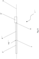
- Fig. 1 and 2 show a schematic representation of a plate-shaped cutting tool 1 according to a first embodiment in plan view and in a side view.
- the cutting tool 1 is realized in the form of an oscillating saw blade, which can be moved in an oscillating manner along the directions 2 with a frequency of, for example, 20,000 strokes per minute.
- a plate-shaped cutting plate 3 which consists of a steel, is brought into contact with a non-metallic material, for example a wood or a bone material. This is done by means of triangular cutting teeth 4, the Fig. 1 the number shown was chosen merely as an example, the cutting plate 3 machines the non-metallic material.
- a corresponding cutting depth or feed can be set via an axial movement parallel to a longitudinal axis 5 of the cutting tool 1 in the direction of the cutting teeth 4.
- the cutting plate 3 is integrally connected to a holding plate 6 via a weld seam 7.
- the weld seam 7, the extent of which in the axial direction is considerably smaller than that of the holding plate 6 and the cutting plate 3, thus forms a boundary region, which can also be referred to as a connecting region, between the cutting plate 3 and the holding plate 6.
- the holding plate 6 can absorb the forces occurring during machining, which can also be referred to as cutting reaction forces.
- the holding plate 6 is monolithic and consists of a hard metal ( cemented carbide ) with a modulus of elasticity of 650 ⁇ 10 9 N/m 2 ; However, other materials within the meaning of the present disclosure are also conceivable and possible.
- the cutting plate 3 is also monolithic, whereby it is made of a steel with a modulus of elasticity of 210 ⁇ 10 9 N/m 2.
- the area 60 of the mounting plate 6 adjacent to the weld seam 7 is thus more rigid than the area 30 of the cutting plate 3 adjacent to the weld seam 7.
- the mounting plate 7 can withstand a deflection of the cutting element 4 in one of the directions perpendicular to the longitudinal axis 5, for example in the directions 2 or one of the directions which are perpendicular to the plane of the drawing of the Fig. 1 oriented, and counteracts them in parallel, so that the influence of cutting reaction forces, which can act on the cutting plate 3 in the area of the cutting teeth 4, on the position of the cutting plate 3 with respect to a fixed reference point located outside the cutting tool 1 is reduced.
- the reference point can therefore be assigned, for example, to a clamping device for clamping and holding the non-metallic material. Since the cutting plate 3 is made of steel, the cutting teeth 4 can be produced by punching and subsequent grinding.
- the weld seam 7 extends over the entire width of the mounting plate 7 and the cutting plate 3, is linear and is oriented perpendicular to the longitudinal axis (another orientation is also conceivable and possible, for example in the case of a different cutting plate 3 and/or a different mounting plate 6 parallel to the longitudinal axis 5 or inclined relative to the longitudinal axis 5, i.e. in the latter case running obliquely).
- the weld seam 7 can therefore be viewed in the geometric sense as a connecting line between two points 100 and 110 of corresponding outer edges 500 of the cutting tool 1.
- the support plate 6 is further connected to a connecting plate 8 via another weld 9.
- the connecting plate 8 is also monolithic, being made of a steel with a modulus of elasticity of 210 ⁇ 10 9 N/m 2 .
- a concave recess 80 of the connecting plate 8 is obtainable by punching, the recess 80 of a drive shaft (not shown) of an electric motor being shaped accordingly, so that the cutting tool 1 can be driven by means of the electric motor to carry out the oscillation movements in the directions 2 can be driven. In this way, a power tool is provided.
- the cutting tool 1 has a constant thickness, which can also be referred to as plate thickness, which is consequently the same in terms of amount in the area of the cutting plate 3, the holding plate 6 and the connecting plate 8.
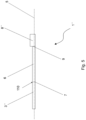
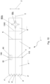
- Fig. 3 shows a schematic representation of a plate-shaped cutting tool 1' according to a second embodiment in a top view or in a side view.
- the cutting tool 1' is constructed analogously to the cutting tool 1, whereby, in contrast to the cutting tool 1, a connecting plate 8', which consists of the steel of the connecting plate 8, has a recess 80a with radial projections 800a and an axial slot 810a, which are formed to correspond to a drive shaft (not shown) of the electric motor in order to transfer more form-fitting forces to the cutting tool 1' compared to the recess 80.
- the connecting plate 8' is longer in the axial direction than the connecting plate 8 of the cutting tool 1, which increases the surface contact with a clamping device of a power tool drive unit.
- the cutting plate 3' is shorter in the axial direction than the cutting plate 3, which makes the cutting plate 4' more rigid.
- the number of cutting teeth 4' is, for example, larger than the number of cutting teeth 4.
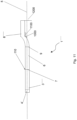
- Fig. 4 and 5 show a schematic representation of a plate-shaped cutting tool 1" according to a third embodiment in a top view and in a side view.
- the cutting tool 1" is constructed analogously to the cutting tool 1, wherein the cutting element 3", which consists of the steel of the cutting element 3, is shown without cutting teeth and a connecting plate 8", which consists of the steel of the connecting plate 8, has a recess 80b with a plug-in groove 800b.
- the cutting tool 1" has a constant thickness, which can also be referred to as plate thickness, in the area of the cutting plate 3" and the mounting plate 6, which in these areas is the same in terms of amount, and has a constant thickness, i.e. plate thickness, in the area of the connecting plate 8", which is greater than the plate thickness in the areas of the cutting plate 3" and the mounting plate 6.
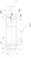
- Fig. 6 and 7 show a schematic representation of a plate-shaped cutting tool 1′′′ according to a fourth embodiment in plan view and in a side view.
- the cutting tool 1′′′ is constructed analogously to the cutting tool 1", whereby, as can be seen from Fig. 7 It is particularly clearly visible that a thickness, i.e. plate thickness, of the cutting tool 1′′′ in the area of a mounting plate 6′′′, starting at the weld seam 7 at a thickness which corresponds to the thickness of the cutting plate 3", continuously increases until the thickness of the connecting plate 8" is reached at the weld seam 9.
- the mounting plate 6′′′ consists of the cemented carbide of the mounting plate 6.
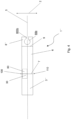
- Fig. 8 and 9 show a schematic representation of a plate-shaped cutting tool 1 ⁇ according to a fifth embodiment in plan view and in a side view.
- the cutting tool 1 ⁇ is constructed analogously to the cutting tool 1′′′, whereby a mounting plate 6 ⁇ , as shown in Fig. 8 as can be seen particularly clearly, has a width measured transversely to the longitudinal axis 2, which becomes continuously smaller from the weld seam 9 to the weld seam 7; at the weld seam 9, the width corresponds to an analogously measured width of the connecting plate 8".
- the cutting tool 1 ⁇ then has a taper, namely in the area of the mounting plate 6 ⁇ .
- the width of the mounting plate 6 ⁇ at the weld seam 7 corresponds to the distance between points 100 ⁇ and 110 ⁇ of corresponding outer edges of the cutting tool 1 ⁇ .
- the mounting plate 6 ⁇ consists of the cemented carbide of the mounting plate 6.
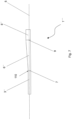
- Fig. 10 and 11 show a schematic representation of a plate-shaped cutting tool 1′′′ ⁇ according to a sixth embodiment in plan view and in a side view.
- the cutting tool 1′′′ ⁇ is constructed analogously to the cutting tool 1', whereby, as can be seen from Fig. 11
- a connecting plate 8′′′ ⁇ which is made of the steel of the Connecting plate 8 consists of two adjacent surfaces 1000 and 1100, which in the side view according to Fig. 11 analogous to a corresponding longitudinal section in the profile, form an inner edge angle of 135°.
- the cutting tool 1′′′ ⁇ is cranked in the area of the connecting plate 8′′′ ⁇ in such a way that, for example, compared to the cutting tool 1, a Fig.
- 11 apparent distance 1200 transverse to the longitudinal axis 5 is obtained in the area of the connecting plate 8′′′ ⁇ , so that the distance 1200 can be used in the sense of an additional assembly space for connecting to an electric motor of a drive unit or the like, whereby - while adhering to the limits of the distance 1200 - a cutting plate 3′′′ ⁇ can at the same time cut a substrate or the like parallel to its Fig. 10 visible areal extension.
- a transition from the surface 1000 to the surface 1100 or vice versa is indicated by a dashed line 1300, which runs parallel to a transverse axis, in Fig. 10
- the connecting plate 8′′′ ⁇ has a radially closed recess 80c with projections 800c for positive connection to a shaft of an electric motor.
- the cutting plate 3′′′ ⁇ which consists of the steel of the cutting plate 3, is longer than the cutting plate 3' in order to gain axial machining space for separating the non-metallic material.
Landscapes
- Engineering & Computer Science (AREA)
- Mechanical Engineering (AREA)
- Health & Medical Sciences (AREA)
- Surgery (AREA)
- Life Sciences & Earth Sciences (AREA)
- Biomedical Technology (AREA)
- Nuclear Medicine, Radiotherapy & Molecular Imaging (AREA)
- Oral & Maxillofacial Surgery (AREA)
- Dentistry (AREA)
- Heart & Thoracic Surgery (AREA)
- Medical Informatics (AREA)
- Molecular Biology (AREA)
- Animal Behavior & Ethology (AREA)
- General Health & Medical Sciences (AREA)
- Public Health (AREA)
- Veterinary Medicine (AREA)
- Cutting Tools, Boring Holders, And Turrets (AREA)
- Drilling Tools (AREA)
Description
- Die vorliegende Erfindung betrifft ein Schneidwerkzeug zum Trennen eines nichtmetallischen Materials, umfassend ein Halterungselement, ein an dem Halterungselement zur schneidenden Kontaktierung des nichtmetallischen Materials gehaltertes Schneidelement und einen an einen Halterungsmaterialbereich des Halterungselements sowie einen Schneidmaterialbereich des Schneidelements angrenzenden Grenzbereich.
- Die vorliegende Erfindung liegt auf dem Gebiet des Trennens, insbesondere indem ein Schneidwerkzeug der eingangs genannten Art in eine oszillierende Schwingung einer Frequenz von beispielsweise 20000 Hüben pro Minute oder mehr bei relativ kleiner Amplitude versetzt wird, eines nichtmetallischen Materials, insbesondere eines solchen, welches üblicherweise mit einer relativ geringen Schnittkraft, insbesondere zerspanend, getrennt werden kann, wie beispielsweise ein Holz oder Hölzer, ein Kunststoff oder Kunststoffe, ein Faserverbundwerkstoff oder Faserverbundwerkstoffe, ein organisches Material oder organische Materialien, ein Gips oder Gipse, ein Gasbeton oder Gasbetons, also ein poröser Beton bzw. Betons, jeweils auf Basis von Kalk-, Kalkzement- oder Zementmörtel, oder ein Knochenmaterial oder Knochenmaterialien jeweils menschlichen oder tierischen Ursprungs.
- Zu den Schneidwerkzeugen der eingangs genannten Art gehören danach insbesondere entsprechende Sägeblätter oder Klingen.
- Aus der
EP 2 295 211 B1 ist ein Schneidwerkzeug der eingangs genannten Art in Form eines Sägeblatts vorbekannt. Das Trennen eines nichtmetallischen Materials, insbesondere - aber nicht nur - wenn dieses ein Knochenmaterial menschlichen oder tierischen Ursprungs ist, mit einem solchen Schneidwerkzeug wird aber dadurch erschwert, dass dieses mitunter in unkontrollierter Weise von einer üblicherweise - aber nicht nur - mittels manueller Führung vorgegebenen Trenn- oder Schnittrichtung abweicht. Ein solches Abweichen kann auch als Ausbrechen des Schneidwerkzeugs bezeichnet werden. - Die
EP 1 558 419 A2 zeigt ein Knochensägeblatt. - Die
US 2019/054552 A1 zeigt eine oszillierende Klinge. - Die
DE 10 2013 203613 A1 zeigt ein Schneidwerkzeug nach dem Oberbegriff des Anspruchs 1, insbesondere ein Tauchsägeblatt. - Die
US 5 178 626 A zeigt ein chirurgisches Sägeblatt. - Die
US 2010/010492 A1 zeigt einen Miniaturhäcksler für medizinische Anwendungen. - Die Aufgabe der vorliegenden Erfindung ist es daher, ein Schneidwerkzeug der eingangs genannten Art bereitzustellen, mit welchem ein präziseres Trennen, insbesondere - aber nicht nur - von Knochenmaterialien menschlichen oder tierischen Ursprungs, möglich ist.
- Diese Aufgabe wird durch ein Schneidwerkzeug mit den Merkmalen nach Anspruch 1 gelöst. Vorteilhafte Weiterbildungen sind den abhängigen Ansprüchen zu entnehmen.
- Das Schneidwerkzeug zum Trennen eines nichtmetallischen Materials umfasst ein Halterungselement, ein an dem Halterungselement zur schneidenden Kontaktierung des nichtmetallischen Materials gehaltertes Schneidelement und einen an einen Halterungsmaterialbereich des Halterungselements sowie einen Schneidmaterialbereich des Schneidelements angrenzenden Grenzbereich, wobei ein Verformungswiderstand gegen eine elastische Verformung des Halterungsmaterialbereichs größer ist als ein Verformungswiderstand gegen eine elastische Verformung des Schneidmaterialbereichs. Dadurch wird das Schneidwerkzeug im Bereich des Halterungselements, welches zum Beispiel plattenförmig ausgeformt sein kann, gegenüber einer elastischen Verformung stabilisiert, so dass das Schneidelement, welches Schneidzähne aufweisen kann, gegen das starrere Halterungselement im Sinne eines Widerlagers beim Trennen gedrückt wird, was zum Beispiel ein Trennen entlang einer vorgegebenen, insbesondere geraden, Trennlinie begünstigt; diese Trennlinie kann insbesondere auf und/oder an einem Knochen, einem Holzwerkstück, einem Kunststoffwerkstück, einem Faserverbundwerkstoffwerkstück, einem organischen Werkstück, einem Gipswerkstück oder einem Gasbetonwerkstück markiert sein. Dies kann noch weiter verbessert werden, indem das Schneidelement entlang einer Längsrichtung des Schneidwerkzeugs kürzer bemessen ist als das Halterungselement, insbesondere wenn das Schneidelement und das Halterungselement jeweils plattenförmig ausgestaltet sind. Das Halterungselement und das Schneidelement sind stoffschlüssig miteinander verbunden. Der Grenzbereich umfasst oder besteht aus einem Stoffschlussmaterial, wie einem Lot und/oder einem Klebematerial, oder einer Materialmischung, umfassend oder bestehend aus Materialien des Halterungselements und des Schneidelements sowie optionalen weiteren Materialien, welche aus einer Stoffschlussverbindungsquelle, zum Beispiel einem Schweißmittel, insbesondere einem Schweißdraht, erhältlich sind. Letzteres ist zum Beispiel durch Herstellung einer Schweißverbindung zwischen dem Halterungselement und dem Schneidelement erhältlich, wonach in diesem Beispiel der Grenzbereich als Schweißnaht oder dergleichen bezeichnet werden kann.
- Vorzugsweise sind der Halterungsmaterialbereich und der Schneidmaterialbereich gegenüberliegend voneinander angeordnet, insbesondere in Draufsicht auf das Schneidwerkzeug. Dadurch wird das Schneidelement noch stabiler gehaltert.
- Mit dem Grenzbereich, welcher auch als erster Grenzbereich bezeichnet werden kann, ist insbesondere ein Bereich gemeint, welcher zumindest abschnittsweise aufgrund einer kraftschlüssigen und/oder formschlüssigen und/oder stoffschlüssigen Verbindung zwischen dem Halterungselement und dem Schneidelement gebildet ist oder werden kann. In Draufsicht auf das Schneidwerkzeug, insbesondere wenn das Halterungselement plattenförmigen ausgebildet ist, kann einem Verlauf des Grenzbereichs insbesondere eine Verbindungslinie, welche innerhalb des Grenzbereichs verläuft, zugeordnet werden, wobei die Verbindungslinie vorzugsweise mindestens zwei, vorzugsweise diametrale Außenkanten, des Schneidwerkzeugs miteinander verbindet. Vorzugsweise mündet die Verbindungslinie in mindestens einen Außenkantenbereich des Schneidwerkzeugs. Die Verbindungslinie kann gerade, gekrümmt oder abschnittsweise gerade oder abschnittsweise gekrümmt verlaufend sein. Die Verbindungslinie kann quer oder parallel zur Längsachse verlaufen. Der Verbindungslinie kann auch eine zwischen diesen beiden Orientierungen liegende Orientierung zugeordnet werden.
- Der Grenzbereich kann einen Materialmischungsbereich umfassen oder vorzugsweise aus diesem bestehen. Der Materialmischungsbereich kann vorzugsweise auf Material des Halterungsmaterialbereichs und Material des Schneidelementbereichs basieren, vorzugsweise daraus bestehen. Alternativ oder ergänzend kann der Materialmischungsbereich auf Material eines Stoffschlussmaterials, beispielsweise eines Lots und/oder eines Klebematerials, basieren, vorzugsweise daraus bestehen.
- Besonders bevorzugt ist das Schneidwerkzeug als Oszillationssägeblatt ausgeformt, wobei das Oszillationssägeblatt über eine Antriebswelle, insbesondere eine Motorwelle, einer Antriebseinheit, insbesondere eines Motor, vorzugsweise eines Elektromotors, in oszillierende Schwingung mit einem vorgegebenen Hub versetzbar ist, so dass das Schneidelement im Bereich eines freien Endes, welches Schneidzähne, welche auch als Sägezähne bezeichnet werden können, aufweist, parallel und/oder senkrecht zu einer Trennrichtung, welche auch als Schnittrichtung bezeichnet werden kann, schwingbar ist. Denn auf diese Weise wird ein besonders präzises oszillierendes Trennen des nichtmetallischen Materials ermöglicht.
- Noch bevorzugter ist es danach, wenn das als Oszillationssägeblatt ausgeformte Schneidwerkzeug mit dem Motor wirkmäßig verbunden ist, so dass auf diese Weise eine Oszillationssäge bereitgestellt wird. Besonders bevorzugt ist es mit dem Motor über ein Getriebe, insbesondere eine Getriebewelle des Getriebes, wirkmäßig verbunden.
- Mit der schneidenden Kontaktierung ist insbesondere gemeint, dass das nichtmetallische Material zerspant wird.
- Indem das Schneidwerkzeug das Halterungselement und das Schneidelement umfasst, ist es dementsprechend zweiteilig ausgebildet. Denkbar und auch möglich ist aber auch eine mehrteilige Ausbildung mit drei oder mehr Elementen, wie beispielsweise einem zusätzlichen Verbindungselement zum formschlüssigen Verbinden mit einem Antriebselement einer Antriebseinheit. Gemäß einer Weiterbildung des Schneidwerkzeugs ist der Verformungswiderstand des Halterungsmaterialbereichs und der Verformungswiderstand des Schneidmaterialbereichs jeweils ein Biegeverformungswiderstand. Danach wird das Trennen des nichtmetallischen Materials insbesondere gegen eine Biegeverformung stabilisiert. Eine solche Stabilisierung kann insbesondere dadurch bereitgestellt werden, dass das Produkt aus einem Elastizitätsmodul eines Materials des Halterungsmaterialbereichs und einem Flächenträgheitsmoment des Halterungsmaterialbereichs größer ist als das Produkt aus einem Elastizitätsmodul eines Materials des Schneidmaterialbereichs und einem Flächenträgheitsmoment des Schneidmaterialbereichs. Diese Produkte können auch als Biegesteifigkeiten des Halterungsmaterialbereichs bzw. des Schneidmaterialbereichs bezeichnet werden. Die Flächenträgheitsmomente sind dabei jeweils bezüglich einer Biegeachse, welche im geometrischen Sinne definiert ist, vorzugsweise bestimmt, die bis auf ihre Position entlang einer Längsachse des Schneidwerkzeugs bezüglich des Halterungselements und des Schneidelements jeweils in derselben Weise positioniert ist, zum Beispiel auf der Hälfte einer im Querschnittschnitt des Halterungselements und des Schneidelements bemessenen Höhe im Falle einer horizontalen Biegeachse.
- Der Halterungsmaterialbereich besteht aus einem Halterungsmaterial und der Schneidmaterialbereich besteht aus einem dem Halterungsmaterial verschiedenen Schneidmaterial. Dadurch kann einerseits die Biegesteifigkeit des Schneidwerkzeugs erhöht werden, indem das Halterungsmaterial beispielsweise auf Basis seines Elastizitätsmoduls ausgewählt wird, und andererseits das Schneidmaterial auf Basis seiner Eignung, das für das schneidende Kontaktieren des nichtmetallischen Materials vorgesehene Schneidelement zu optimieren, ausgewählt werden. Letztere Eignung kann beispielsweise dadurch ausgedrückt werden, dass Schneidzähne mit definierten Schneidzahnflanken, insbesondere in reprozierbarer Weise, hergestellt werden können. Hierfür kommt insbesondere Stahl als Schneidmaterial in Betracht.
- Vorzugsweise besteht das Halterungselement aus dem Halterungsmaterial, was zu einer noch besseren Stabilisierung des Schneidelements beim Trennen beiträgt.
- Vorzugsweise besteht das Schneidelement aus dem Schneidmaterial, wonach das Schneidelement bei geeigneter Wahl des Schneidmaterials für das Trennen eines bestimmten nichtmetallischen Materials und/oder zur Aufnahme von Reaktionskräften und thermischen Belastungen, welche auf das Schneidelement beim Trennen wirken können, ausgewählt werden kann.
- Ein Elastizitätsmodul des Halterungsmaterials ist größer als ein Elastizitätsmodul des Schneidmaterials. Dadurch kann in vorteilhafter Weise die Biegesteifigkeit des Schneidwerkzeugs unter vorteilhafter Vermeidung besonderer konstruktiver Maßnahmen erhöht werden. So kann der Elastizitätsmodul des Halterungsmaterials beispielsweise um einen Faktor 1,1 bis 5 oder mehr größer sein als der Elastizitätsmodul des Schneidmaterials. Bevorzugte Werte dieses Bereichs, also des Faktors, sind 1,1, 1,2, 1,3, 1,4, 1,5, 1,6, 1,7, 1,8, 1,9, 2,0, 2,1, 2,2, 2,3, 2,4, 2,5, 2,6, 2,7, 2,8, 2,9, 3,0, 3,1, 3,2, 3,3, 3,4, 3,5, 3,6, 3,7, 3,8, 3,9, 4,0, 4,1, 4,2, 4,3, 4,4, 4,5, 4,6, 4,7, 4,8, 4,9 oder 5,0.
- Mit dem Elastizitätsmodul des Schneidmaterials und des Halterungsmaterials sind insbesondere auch die für die jeweilige elastische Verformung des Schneidmaterialbereichs und des Halterungsmaterialbereichs relevante Komponente oder Komponenten eines dem Schneidmaterial und dem Halterungsmaterial jeweils zuordenbaren Elastizitätstensors gemeint, sofern das Schneidmaterial bzw. das Halterungsmaterial elastisch anisotrop sind.
- Vorzugsweise besteht das Halterungselement aus dem Halterungsmaterialbereich, was zu einer noch besseren Stabilisierung des Schneidwerkzeugs beim Trennen beiträgt.
- Vorzugsweise besteht das Schneidelement aus dem Schneidmaterialbereich, wonach das Schneidelement bei geeigneter Wahl des Schneidmaterialbereichs für das Trennen eines bestimmten nichtmetallischen Materials und/oder zur Aufnahme entsprechender Reaktionskräfte, welche auf das Schneidelement beim Trennen wirken können, ausgewählt werden kann.
- Gemäß einer Weiterbildung des Schneidwerkzeugs weist das Halterungsmaterial eine Materialmatrix mit einer Matrixduktilität und in der Materialmatrix angeordnete Hartstoffpartikel mit einer Partikelduktilität, welche kleiner ist als die Matrixduktilität, auf. Dadurch wird das Halterungsmaterial zur weiteren Erhöhung der Biegesteifigkeit und Steigerung der Verschleißfestigkeit des Schneidwerkzeugs in Form eines Verbundwerkwerkstoffs bereitgestellt. Die Hartstoffpartikel können zum Beispiel aus Wolframcarbid (WC) und die Materialmatrix aus Cobalt (Co) oder einem Mischkristall auf Basis von Cobalt (Co) bestehen. Danach handelt es sich bei dem Halterungsmaterial um ein Hartmetall (cemented carbide). Vorzugsweise sind die Hartstoffpartikel aus WC kleiner oder gleich 20 µm, vorzugsweise kleiner oder gleich 20 µm, 19 µm, 18 µm, 17 µm, 16 µm, 15 µm, 14 µm, 13 µm, 12 µm, 11 µm, 10 µm, 9 µm, 8 µm, 7 µm, 6 µm, 5 µm, 4 µm, 3 µm, 2 µm, 1 µm, 0,5 µm, 0,4 µm, 0,3 µm, 0,2 µm oder 0,1 µm. Vorzugsweise beträgt der Cobalt-Gehalt, in elementarer Form oder als Mischkristall, bezogen auf die Gesamtzusammensetzung des Halterungsmaterials 3 bis 30 Gewichtsprozent (bevorzugte Werte, also Gewichtsprozente, dieses Bereichs sind 3, 4, 5, 6, 7, 8, 9, 10, 11, 12, 13, 14, 15, 16, 17, 18, 19, 20, 21, 22, 23, 24, 25, 26, 27, 28, 29 oder 30); den entsprechenden Rest bilden die Hartstoffpartikel aus WC und optional andere Hartstoffpartikel wie Vanadiumcarbid (VC), Chromcarbid (Cr2C3) und/oder Tantal-Niob-Carbid (Ta,Nb)C. Alternativ oder ergänzend können die Hartstoffpartikel aus Titancarbid (TiC), Titannitrid (TiN) und/oder Tantalcarbid (TaC) und die Materialmatrix aus Niob (Nb), Molybdän (Mo) oder Kobalt (Co) bzw. entsprechenden Mischkristallen dieser Elemente bestehen. Danach handelt es sich bei dem Halterungsmaterial um ein Cermet (cermet). Vorzugsweise sind die Hartstoffpartikel aus Titancarbid (TiC), Titannitrid (TiN) und/oder Tantalcarbid (TaC) kleiner oder gleich 20 µm, vorzugsweise kleiner oder gleich 20 µm, 19 µm, 18 µm, 17 µm, 16 µm, 15 µm, 14 µm, 13 µm, 12 µm, 11 µm, 10 µm, 9 µm, 8 µm, 7 µm, 6 µm, 5 µm, 4 µm, 3 µm, 2 µm, 1 µm, 0,5 µm, 0,4 µm, 0,3 µm, 0,2 µm oder 0,1 µm. Vorzugsweise beträgt der Niob- (Nb), Molybdän- (Mo) oder Kobalt-Gehalt (Co), jeweils in elementarer Form oder als Mischkristall, bezogen auf die Gesamtzusammensetzung des Halterungsmaterials 3 bis 30 Gewichtsprozent (bevorzugte Werte, also Gewichtsprozente, dieses Bereichs sind 3, 4, 5, 6, 7, 8, 9, 10, 11, 12, 13, 14, 15, 16, 17, 18, 19, 20, 21, 22, 23, 24, 25, 26, 27, 28, 29 oder 30); den entsprechenden Rest bilden die Hartstoffpartikel aus Titancarbid (TiC), Titannitrid (TiN) und/oder Tantalcarbid (TaC) und optional andere Hartstoffpartikel. Vorzugsweise ist das Halterungsmaterial im Falle der Bereitstellung als Cermet nickelfrei.
- Gemäß einer Weiterbildung des Schneidwerkzeugs ist das Halterungsmaterial ein keramisches Material, ein Refraktärmetall oder eine Mischung daraus.
- Dadurch wird das Halterungsmaterial zur weiteren Erhöhung der Biegesteifigkeit bereitgestellt. Bei dem Refraktärmetall kann es sich zum Beispiel um ein Molybdän- oder Wolfram-Metall handeln, welches sich jeweils in vorteilhafterweise zu dem Halterungselement um- und/oder urformen lässt und zugleich einen relativ hohen Elastizitätsmodul zur vorteilhaften Steigerung der Biegesteifigkeit aufweist. Bei der Keramik kann es sich zum Beispiel um eine Oxidkeramik auf Basis von Aluminiumoxid, Magnesiumoxid, Zirkoniumoxid oder Titandioxid handeln. Vorzugsweise ist die Oxidkeramik eine mit Zirkonium verstärkte Aluminiumoxid-Keramik. Alternativ kann es sich bei der Keramik um eine im Wesentlichen, vorzugsweise gänzlich, oxidfreie Keramik handeln, also insbesondere eine Keramik auf Basis von Carbiden, Nitriden, Boriden und/oder Siliciden.
- Gemäß einer Weiterbildung des Schneidwerkzeugs ist das Halterungselement monolithisch. Danach wird ein besonders biegesteifes Schneidwerkzeug bereitgestellt. Mit monolithisch ist insbesondere gemeint, dass von einem beliebigen Ende des Halterungselements beginnend nach einem anderen beliebigen Ende des Halterungselements ein homogener Materialpfad gebildet ist.
- Gemäß einer Weiterbildung des Schneidwerkzeugs ist das Schneidmaterial ein metallisches Material, insbesondere ein Stahl, und ist eine Duktilität des Schneidmaterials größer als eine Duktilität des Halterungsmaterials. Dadurch wird das Schneidmaterial gegenüber dem Halterungsmaterial als relativ duktiles Material bereitgestellt, wonach zum Beispiel die Herstellung von Schneidzähnen in und/oder an einem Schneidelementrohkörper, aus welchem das Schneidelement herstellbar ist oder hergestellt ist, mit definierten Zahnflanken in erleichterter, vorzugsweise reproduzierbarer, Weise ermöglicht wird, insbesondere durch Stanzen in Kombination mit optionalen weiteren Herstellungsschritten wie Schleifen, Fräsen, Sägen oder dergleichen. Die Duktilität des Schneidmaterials und des Halterungsmaterials können dabei anhand einer aus einem Zugversuch erhältlichen Gleichmaßdehnung oder Bruchdehnung bemessen sein. Die Bruchdehnung des Schneidmaterials in Form des metallischen Materials, insbesondere des Stahls, ist vorzugsweise um mindestens einen Faktor 2 bis 50 größer als die Bruchdehnung des Halterungsmaterials. Bevorzugte Werte dieses Bereichs, also des Faktors, sind 50, 49, 48, 47, 46, 45, 44, 43, 42, 41, 40, 39, 38, 37, 36, 35, 34, 33, 32, 31, 30, 29, 28, 27, 26, 25, 24, 23, 22, 21, 20, 19, 18, 17, 16, 15, 14, 13, 12, 11, 10, 9, 8, 7, 6, 5, 4, 3 oder 2.
- Gemäß einer Weiterbildung des Schneidwerkzeugs sind der Halterungsmaterialbereich und der Schneidmaterialbereich mittels einer Klebeverbindung, einer Lötverbindung oder einer Schweißverbindung, insbesondere einer Strahlschweißverbindung, stoffschlüssig miteinander verbunden. Dadurch wird jeweils eine besonders vorteilhafte stoffschlüssige Verbindung zwischen dem Halterungsmaterialbereich und dem Schneidmaterialbereich bereitgestellt. Mit der Strahlschweißverbindung ist insbesondere gemeint, dass eine zum Aufschmelzen des Halterungsmaterials und/oder des Schneidmaterials erforderliche Schmelzenergie aus einem oder mehreren Laserstrahlen und/oder Elektronenstrahlen erhältlich ist.
- Gemäß einer Weiterbildung des Schneidwerkzeugs ist der Grenzbereich zwischen zwei Außenkantenpunkten des Schneidwerkzeugs erstreckend ausgeformt. Dies ist eine für die, insbesondere stoffschlüssige, stabile Verbindung des Schneidelements mit dem Halterungselement besonders vorteilhafte Maßnahme. Dies zum Beispiel im Sinne einer Schweißnaht oder dergleichen. Vorzugsweise erstrecken sich der Halterungsmaterialbereich und der Schneidelementmaterialbereich zwischen den beiden Außenkantenpunkten.
- Gemäß einer Weiterbildung des Schneidwerkzeugs ist der Grenzbereich in einen ersten Außenkantenbereich des Schneidwerkzeugs und in einen zweiten Außenkantenbereich des Schneidwerkzeugs mündend. Dies ist eine für die, insbesondere stoffschlüssige, stabile Verbindung des Schneidelements mit dem Halterungselement besonders vorteilhafte Maßnahme. Die beiden Außenkantenbereiche können an derselben oder verschiedenen Längsachsenpositionen bezüglich einer Längsachse des Schneidwerkzeugs angeordnet sein. Die beiden Außenkantenbereiche können mittels einer Verbindungslinie verbunden werden, welche parallel, senkrecht oder in einem von 90° verschiedenen Winkel, zum Beispiel 0° bis 89°, vorzugsweise 1°, 2°, 3°, 4°, 5°, 10°, 15°, 20°, 25°, 30°, 35°, 40°, 45°, 50°, 55°, 60°, 65°, 70°, 75°, 85°, 89°, gegenüber einer Längsachse des Schneidwerkzeugs orientiert ist. Die beiden Außenkantenbereiche können vorzugsweise jeweils Oberflächenbereiche verschiedener Seitenflächen, welcher vorzugsweise jeweils kleiner sind als eine in einer Draufsicht auf das Halterungselement ersichtliche Oberfläche des Halterungselements, des Schneidwerkzeugs sein, welche in entsprechenden Seitenansichten des Schneidwerkzeugs ersichtlich sind.
- Gemäß einer Weiterbildung des Schneidwerkzeugs sind in Draufsicht auf das Schneidwerkzeug mindestens zwei Außenkantenpunkte des Schneidwerkzeugs zwischen dem Halterungsmaterialbereich und dem Schneidmaterialbereich angeordnet. Dadurch bildet der Halterungsmaterialbereich in vorteilhafter Weise zum Beispiel eine Stoffschlussfläche, an welcher das Schneidelement stoffschlüssig mit dem Halterungselement verbunden werden kann oder ist. Die Außenkantenpunkte können mittels einer Verbindungsgeraden verbunden sein, welche senkrecht zur einer Längsachse verläuft oder gegenüber der Längsachse, insbesondere in einer Ebene des Halterungselements, geneigt verläuft, zum Beispiel quer dazu.
- Die Stoffschlussfläche, welche vorzugsweise eine Stirnfläche des Halterungselements, welches plattenförmig ausgestaltet sein kann, ist, kann eine dieser korrespondierend ausgeformte Kontaktierungsfläche des Schneidelements im Wesentlichen, vorzugsweise gänzlich, spaltfrei kontaktieren, wonach eine besonders vorteilhafte, weil kontaktierungsmaximierende stoffschlüssige Verbindung zwischen dem Schneidelement und dem Halterungselement realisiert werden kann. Die Stoffschlussfläche und die Kontaktierungsfläche können danach vorzugsweise als jeweils ebene Flächen oder als konvex-konkaves Flächenpaar vorliegen. Im letzteren Falle ist vorzugsweise die Stoffschlussfläche konkav und die Kontaktierungsfläche dementsprechend konvex.
- Gemäß einer Weiterbildung des Schneidwerkzeugs weist ein Außenbereich des Halterungsmaterialbereichs zumindest abschnittsweise eine Fase oder eine Kantenverrundung auf. Durch diese Maßnahmen wird in vorteilhafter Weise das Risiko minimiert, dass eine ansonsten rechtwinklige Außenkante des Halterungsmaterialbereichs, zumindest teilweise, bricht und damit weiteres Risswachstum begünstigt.
- Gemäß einer Weiterbildung des Schneidwerkzeugs sind zwei Außenkanten des Halterungsmaterialbereichs durch eine konvexe Sehne verbunden. Durch diese Maßnahmen wird in vorteilhafter Weise das Risiko minimiert, dass eine ansonsten rechtwinklige Außenkante des Halterungsmaterialbereichs, zum zumindest teilweise, bricht und damit weiteres Risswachstum begünstigt.
- Gemäß einer Weiterbildung des Schneidwerkzeugs umfasst das Schneidwerkzeug ein Verbindungselement zum formschlüssigen Verbinden mit einem Antriebselement einer Antriebeinheit, wobei das Verbindungselement an dem Halterungselement gehaltert ist, ein Grenzbereich, welcher auch als zweiter Grenzbereich zur Unterscheidung von dem an den Halterungsmaterialbereich und den Schneidmaterialbereich angrenzenden Grenzbereich bezeichnet werden kann, zwischen dem Verbindungselement und dem Halterungselement gebildet ist und eine Duktilität eines Verbindungsmaterials des Verbindungselements größer ist als eine Duktilität des Halterungsmaterials. Dadurch wird das Schneidwerkzeug mit Verbinden mit dem Antriebselement, welches insbesondere eine Motorwelle eines Elektromotors oder eine Abtriebswelle eines mit der Motorwelle verbundenen Getriebes sein kann, in vorteilhafterweise bereitgestellt. Ferner wird das Verbindungsmaterial gegenüber dem Halterungsmaterial als relativ duktiles Material bereitgestellt, wonach zum Beispiel die Herstellung einer Ausnehmung zum formschlüssigen Verbinden mit dem Antriebselement besonders einfach, zum Beispiel durch Stanzen, Sägen oder Fräsen, möglich ist. Die Duktilität des Verbindungsmaterials und des Halterungsmaterials können dabei anhand einer aus einem Zugversuch erhältlichen Gleichmaßdehnung oder Bruchdehnung bemessen sein. Die Bruchdehnung des Verbindungsmaterials ist vorzugsweise um mindestens einen Faktor 2 bis 50 größer als die Bruchdehnung des Halterungsmaterials. Bevorzugte Werte dieses Bereichs, also des Faktors, sind 50, 49, 48, 47, 46, 45, 44, 43, 42, 41, 40, 39, 38, 37, 36, 35, 34, 33, 32, 31, 30, 29, 28, 27, 26, 25, 24, 23, 22, 21, 20, 19, 18, 17, 16, 15, 14, 13, 12, 11, 10, 9, 8, 7, 6, 5, 4, 3 oder 2. Das Verbindungselement ist vorzugsweise plattenförmig. Das Verbindungselement und das Halterungselement sind vorzugsweise formschlüssig miteinander verbunden. Vorzugsweise ist ein Verformungswiderstand gegen eine elastische Verformung eines an den zweiten Grenzbereich angrenzenden Halterungsmaterialbereichs des Halterungselements größer als ein Verformungswiderstand gegen eine elastische Verformung eines an den zweiten Grenzbereich angrenzenden Verbindungsmaterialbereichs des Verbindungselements. Vorzugsweise ist die elastische Verformung des Halterungsmaterialbereichs und die elastische Verformung des Verbindungsmaterialbereichs jeweils eine Biegeverformung. Vorzugsweise besteht der Halterungsmaterialbereich aus dem Halterungsmaterial und besteht der Verbindungsmaterialbereichs aus dem Halterungsmaterial verschiedenen Verbindungsmaterial. Vorzugsweise ist ein Elastizitätsmodul des Halterungsmaterials größer ist als ein Elastizitätsmodul des Verbindungsmaterials. Vorzugsweise ist das Halterungsmaterial ein Hartmetall (cemented carbide), ein Cermet (cermet), ein keramisches Material, ein Refraktärmetall oder eine Mischung daraus. Vorzugsweise ist der an den zweiten Grenzbereich angrenzende Halterungsmaterialbereich der an den (ersten) Grenzbereich angrenzende Halterungsmaterialbereich. Vorzugsweise ist das Verbindungselement monolithisch.
- Gemäß einer Weiterbildung des Schneidwerkzeugs ist das Verbindungsmaterial ein metallisches Material, insbesondere ein Stahl. Hierbei handelt es sich mit Vorteil für die Herstellung einer Ausnehmung zum formschlüssigen Verbinden mit dem Antriebselement in dem Verbindungselement um ein besonders einfach zu bearbeitendes sowie relativ kostengünstiges Material.
- Gemäß einer Weiterbildung des Schneidwerkzeugs sind das Halterungselement und das Verbindungselement mittels einer Klebeverbindung, einer Lötverbindung oder einer Schweißverbindung, insbesondere einer Strahlschweißverbindung, stoffschlüssig miteinander verbunden. Dadurch wird jeweils eine besonders vorteilhafte stoffschlüssige Verbindung zwischen dem Halterungselement und dem Verbindungselement bereitgestellt. Mit der Strahlschweißverbindung ist insbesondere gemeint, dass eine zum Aufschmelzen des Halterungsmaterials und/oder des Verbindungsmaterials erforderliche Schmelzenergie aus einem oder mehreren Laserstrahlen und/oder Elektronenstrahlen erhältlich ist.
- Gemäß einer Weiterbildung des Schneidwerkzeugs sind in einem Längsschnitt des Schneidwerkzeugs eine erste Oberfläche und eine an die erste Oberfläche angrenzende zweite Oberfläche einen kleiner 180° bemessenen Innenkantenwinkel bildend angeordnet. Dadurch kann in vorteilhafterweise das Kollisionsrisiko einer mit dem Schneidwerkzeug verbundenen Antriebseinheit mit dem nichtmetallischen Material verringert werden, insbesondere zur Realisierung einer geradlinigen Führung des Schneidwerkzeugs, wenn das Schneidelement, insbesondere nahezu, flächenmäßig ein anderes Bauteil kontaktiert. Dies kann auch als Kröpfung des Schneidwerkzeugs bezeichnet werden. Vorzugsweise ist der Innenkantenwinkel, welcher auch als erster Innenkantenwinkel bezeichnet werden kann, kleiner oder gleich 180°, 175°, 170°, 165°, 160°, 155°, 150°, 145°, 140°, 135°, 130°, 125°, 120°, 115°, 110°, 105°, 100°, 95° oder 90°. Vorzugsweise ist der Innenkantenwinkel größer 90° und kleiner 180°, einschließlich 175°, 170°, 165°, 160°, 155°, 150°, 145°, 140°, 135°, 130°, 125°, 120°, 115°, 110°, 105°, 100°, 95°. Vorzugsweise wird danach ein Stich- und/oder Tauchsägeblatt in Form des Schneidwerkzeugs optional bereitgestellt. Vorzugsweise sind die erste und die zweite Oberfläche Oberflächen des optionalen Verbindungselements und/oder des Halterungselements. Vorzugsweise ist eine der Oberflächen eine Oberfläche des Halterungselements und die andere eine Oberfläche des Verbindungselements. Vorzugsweise ist eine der Oberflächen eine Oberfläche des Halterungselements und die andere eine Oberfläche des Schneidelements.
- Gemäß einer Weiterbildung des Schneidwerkzeugs ist eine axiale Abmessung des Grenzbereichs und/oder des zweiten Grenzbereichs kleiner als eine axiale Abmessung des Halterungselements. Dadurch kann in vorteilhafterweise eine Lokalisierung der elastischen Verformung, zum Beispiel in Form eines Maximums einer Biegelinie, außerhalb des Grenzbereichs bzw. des zweiten Grenzbereichs bereitgestellt werden. Mit axialer Abmessung ist insbesondere eine parallel zu einer Längsachse des Schneidwerkzeugs bemessene Abmessung gemeint.
- Gemäß einer Weiterbildung des Schneidwerkzeugs ist eine axiale Abmessung des Halterungselements größer oder gleich einer axialen Abmessung des Schneidelements. Dadurch wird die Biegesteifigkeit des Schneidwerkzeugs in vorteilhafterweise noch mehr gesteigert. Mit axialer Abmessung ist insbesondere eine parallel zu einer Längsachse des Schneidwerkzeugs bemessene Abmessung gemeint.
- Gemäß einer Weiterbildung des Schneidwerkzeugs ist bzw. sind der Grenzbereich und/oder zweite Grenzbereich linienförmig, insbesondere in Draufsicht auf das Schneidwerkzeug. Danach handelt es sich bei dem Grenzbereich bzw. dem zweiten Grenzbereich zum Beispiel um eine Schweißnaht oder eine Lötnaht oder eine Klebenaht.
- Gemäß einer Weiterbildung des Schneidwerkzeugs weist das Halterungselement eine Verjüngung, vorzugsweise quer zu einer Längsachse des Schneidwerkzeugs, auf. Hierbei handelt es sich um eine besonders vorteilhafte Form des Halterungselements. Vorzugsweise ist die Verjüngung am Grenzbereich und/oder zweiten Grenzbereich ausgebildet.
- Das Schneidelement weist Schneidzähne auf. Dadurch wird die Trennleistung des Schneidwerkzeugs in vorteilhafterweise erhöht. Vorzugsweise bilden die Schneidzähne eine Schneidzahnreihe aus beispielsweise mindestens 10 oder mehr, beispielsweise mehr als 20, 30, 40, 50, 60, 70, 80, 90, 100, 110, 120, 130, 140, 150, 160, 170, 180, 190, 200, 250, 300, 350, 400, 500, 600, 700, 800, 900 oder 1000 Schneidzähne, nach außen spitz zulaufenden dreieckförmigen Zähnen. Vorzugsweise ist der Schneidzahnreihe eine Begrenzungslinie zuordenbar, welche vorzugsweise gerade oder rund sein kann. Vorzugsweise sind die Schneidzähne zueinander verschränkt angeordnet.
- Gemäß einer Weiterbildung des Schneidwerkzeugs ist das Schneidwerkzeug manuell führbar ausgestaltet. Dadurch kann das Schneidwerkzeug insbesondere mittels eines relativ geringen Kraftaufwandes entlang einer Schnittlinie geführt werden. Vorzugsweise kann das Schneidwerkzeug nach dieser Weiterbildung mit einer handführbaren Werkzeugmaschine und/oder einem Elektrowerkzeug handführbaren verbunden werden.
- Gemäß einer Weiterbildung ist das Schneidwerkzeug vorzugsweise plattenförmig ausgebildet. Hierbei handelt es sich um eine besonders einfach herzustellende Form.
- Gemäß einer Weiterbildung des Schneidwerkzeugs ist diesem in einer Seitenansicht eine Dickenabmessung zuordenbar, wobei eine entsprechende Dicke entlang einer Längsachse des Schneidwerkzeugs vorzugsweise veränderlich ist, insbesondere im Bereich des Halterungselements und/oder des Schneidelements und/oder des Verbindungselements. Vorzugsweise ist die Dicke im Bereich des Verbindungselements größer als im Bereich des Schneidelements. Dies trägt zur weiteren Stabilisierung des Schneidwerkzeugs bei. Alternativ kann die Dicke jeweils im Bereich des Halterungselements und des Schneidelements und optional im Bereich des Verbindungselements kontant sein, wobei vorzugsweise die Dicke im Bereich des Halterungselements von der Dicke im Bereich des Schneidelements und/oder des Verbindungselements verschieden sein kann. Wenn die Dicke in diesen Bereichen betragsmäßig dieselbe ist, kann das Schneidwerkzeug besonders kostengünstig hergestellt werden, insbesondere mittels Schleifen oder dergleichen.
- Gemäß einer Weiterbildung des Schneidwerkzeugs ist diesem in einer Draufsicht eine Breitenabmessung, sprich Breite, zuordenbar, wobei eine entsprechende Breite entlang einer Längsachse des Schneidwerkzeugs vorzugsweise veränderlich ist, insbesondere im Bereich des Halterungselements und/oder des Schneidelements und/oder des Verbindungselements. Vorzugsweise ist die Breite im Bereich des Verbindungselements größer als im Bereich des Schneidelements. Dies trägt zur weiteren Stabilisierung des Schneidwerkzeugs bei. Alternativ kann die Breite jeweils im Bereich des Halterungselements und des Schneidelements und optional im Bereich des Verbindungselements kontant sein, wobei vorzugsweise die Breite im Bereich des Halterungselements von der Breite im Bereich des Schneidelements und/oder des Verbindungselements verschieden sein kann.
- Gemäß einer Weiterbildung des Schneidwerkzeugs ist diesem in einer Draufsicht eine Breitenabmessung, sprich eine Breite, und in einer Seitenansicht eine Dickenabmessung, sprich Dicke, zuordenbar, wobei eine entsprechende Breite und eine entsprechende Dicke entlang einer Längsachse des Schneidwerkzeugs vorzugsweise veränderlich sind, insbesondere im Bereich des Halterungselements und/oder des Schneidelements und/oder des Verbindungselements. Vorzugsweise ist die Breite und/oder die Dicke im Bereich des Verbindungselements größer als im Bereich des Schneidelements. Dies trägt zur weiteren Stabilisierung des Schneidwerkzeugs bei. Alternativ kann die Breite und/oder Dicke jeweils im Bereich des Halterungselements und des Schneidelements und optional im Bereich des Verbindungselements kontant sein, wobei vorzugsweise die Dicke und/oder die Breite im Bereich des Halterungselements von der Dicke und/oder Breite im Bereich des Schneidelements und/oder des Verbindungselements verschieden sein kann.
- Weitere Vorteile und Zweckmäßigkeiten der Erfindung ergeben sich anhand der nachfolgenden Beschreibung von Ausführungsbeispielen unter Bezugnahme auf die beigefügten Figuren.
- Von den Figuren zeigen:
- Fig. 1:
- eine schematische Darstellung eines Schneidwerkzeugs nach einer ersten Ausführungsform in Draufsicht;
- Fig. 2:
- eine schematische Darstellung des Schneidwerkzeugs nach
Fig. 1 in einer Seitenansicht; - Fig. 3:
- eine schematische Darstellung eines Schneidwerkzeugs nach einer zweiten Ausführungsform in Draufsicht;
- Fig. 4:
- eine schematische Darstellung eines Schneidwerkzeugs nach einer dritten Ausführungsform in Draufsicht;
- Fig. 5:
- eine schematische Darstellung des Schneidwerkzeugs nach
Fig. 4 in einer Seitenansicht; - Fig. 6:
- eine schematische Darstellung eines Schneidwerkzeugs nach einer vierten Ausführungsform in Draufsicht;
- Fig. 7:
- eine schematische Darstellung des Schneidwerkzeugs nach
Fig. 6 in einer Seitenansicht; - Fig. 8:
- eine schematische Darstellung eines Schneidwerkzeugs nach einer fünften Ausführungsform in Draufsicht;
- Fig. 9:
- eine schematische Darstellung des Schneidwerkzeugs nach
Fig. 8 in einer Seitenansicht; - Fig. 10:
- eine schematische Darstellung eines Schneidwerkzeugs nach einer sechsten Ausführungsform in Draufsicht; und
- Fig. 11:
- eine schematische Darstellung des Schneidwerkzeugs nach
Fig. 10 in einer Seitenansicht. - In den
Figuren 1 bis 11 werden gleiche, ähnliche oder gleichwirkende Elemente mit identischen Bezugszeichen bezeichnet und auf eine wiederholte Beschreibung dieser Elemente wird in der nachfolgenden Beschreibung verzichtet, um Redundanzen zu vermeiden. -
Fig. 1 und2 zeigen eine schematische Darstellung eines plattenförmigen Schneidwerkzeugs 1 nach einer ersten Ausführungsform in Draufsicht beziehungsweise in einer Seitenansicht. Das Schneidwerkzeug 1 ist in Form eines Oszillationssägeblattes realisiert, welches entlang der Richtungen 2 mit einer Frequenz von beispielsweise 20000 Hüben pro Minute ozillizierend bewegt werden kann. Bei einer solchen Oszillation wird eine plattenförmige Schneidplatte 3, welche aus einem Stahl besteht, in Kontakt mit einem nichtmetallischen Material, zum Beispiel einem Holz oder einem Knochenmaterial, gebracht. Dabei erfolgt mittels dreieckförmiger Schneidzähne 4, deren inFig. 1 ersichtliche Anzahl lediglich exemplarisch gewählt wurde, der Schneidplatte 3 eine Zerspanung des nichtmetallischen Materials. Eine entsprechende Schnitttiefe bzw. ein Vorschub kann dabei über eine axiale Bewegung parallel zu einer Längsachse 5 des Schneidwerkzeugs 1 in Richtung der Schneidzähne 4 eingestellt werden. Die Schneidplatte 3 ist mit einer Halterungsplatte 6 stoffschlüssig über eine Schweißnaht 7 verbunden. Die Schweißnaht 7, deren Erstreckung in axialer Richtung wesentlich kleiner ist als die der Halterungsplatte 6 und der Schneidplatte 3, bildet also einen Grenzbereich, welcher auch als Verbindungsbereich bezeichnet werden kann, zwischen der Schneidplatte 3 und der Halterungsplatte 6. Dadurch kann die Halterungsplatte 6 die bei der Zerspanung auftretenden Kräfte, welche auch als Schnittreaktionskräfte bezeichnet werden können, aufnehmen. Die Halterungsplatte 6 ist monolithisch und besteht aus einem Hartmetall (cemented carbide) mit einem Elastizitätsmodul von 650·109 N/m2; denkbar und auch möglich sind aber auch andere Materialien im Sinne der vorliegenden Offenbarung. Die Schneidplatte 3 ist ebenfalls monolithisch, wobei sie aus einem Stahl mit einem Elastizitätsmodul von 210·109 N/m2 besteht. Damit ist der an die Schweißnaht 7 angrenzende Bereich 60 der Halterungsplatte 6 biegesteifer als der an die Schweißnaht 7 angrenzende Bereich 30 der Schneidplatte 3. Dies führt dazu, dass die Halterungsplatte 7 einer Auslenkung des Schneidelements 4 in eine der Richtungen senkrecht zur Längsachse 5, zum Beispiel in die Richtungen 2 oder eine der Richtungen, welche senkrecht zur Zeichnungsebene derFig. 1 orientiert sind, und parallel dazu entgegenwirkt, so dass der Einfluss von Schnittreaktionskräften, welche auf die Schneidplatte 3 im Bereich der Schneidzähne 4 einwirken können, auf die Position der Schneidplatte 3 bezüglich eines außerhalb des Schneidwerkzeugs 1 befindlichen sowie ortsfesten Bezugspunkts reduziert wird. Der Bezugspunkt kann also beispielsweise einer Spannvorrichtung zum Spannen sowie zum Haltern des nichtmetallischen Materials zugeordnet werden. Indem die Schneidplatte 3 aus einem Stahl besteht, können die Schneidzähne 4 durch Stanzen mit anschließendem Schleifen hergestellt werden. - In
Fig. 1 ist besonders gut ersichtlich, dass sich die Schweißnaht 7 über die gesamte Breite der Halterungsplatte 7 und der Schneidplatte 3 erstreckt, linienförmig ist und senkrecht zur Längsachse orientiert ist (denkbar und auch möglich ist auch eine andere Orientierung, zum Beispiel im Falle einer anderen Schneidplatte 3 und/oder einer anderen Halterungsplatte 6 parallel zur Längsachse 5 oder gegenüber der Längsachse 5 geneigt, sprich im letzteren Fall schräg verlaufend). Die Schweißnaht 7 kann daher im geometrischen Sinne als Verbindungslinie zwischen zwei Punkten 100 und 110 entsprechender Außenkanten 500 des Schneidwerkzeugs 1 betrachtet werden. - Die Halterungsplatte 6 ist ferner mit einer Verbindungsplatte 8 über eine andere Schweißnaht 9 verbunden. Die Verbindungsplatte 8 ist ebenfalls monolithisch, wobei sie aus einem Stahl mit einem Elastizitätsmodul von 210·109 N/m2 besteht. Indem die Verbindungsplatte 8 aus Stahl besteht, ist eine konkave Ausnehmung 80 der Verbindungsplatte 8 durch Stanzen erhältlich, wobei die Ausnehmung 80 einer nicht dargestellten Antriebswelle eines Elektromotors korrespondierend ausgeformt ist, so dass das Schneidwerkzeug 1 mittels des Elektromotors zur Ausführung der Oszillationsbewegungen in die Richtungen 2 angetrieben werden kann. Auf diese Weise wird ein Elektrowerkzeug bereitgestellt.
- In
Fig. 2 ist besonders gut ersichtlich, dass das Schneidwerkzeug 1 eine konstante Dicke, welche auch als Plattenstärke bezeichnet werden kann, aufweist, welche folglich im Bereich der Schneidplatte 3, der Halterungsplatte 6 und der Verbindungsplatte 8 betragsmäßig dieselbe ist. -
Fig. 3 zeigt eine schematische Darstellung eines plattenförmigen Schneidwerkzeugs 1' nach einer zweitem Ausführungsform in Draufsicht beziehungsweise in einer Seitenansicht. Das Schneidwerkzeug 1' ist dem Schneidwerkzeug 1 analog aufgebaut, wobei im Unterschied zum Schneidwerkzeug 1 eine Verbindungsplatte 8', welche aus dem Stahl der Verbindungsplatte 8 besteht, eine Ausnehmung 80a mit radialen Auskragungen 800a und einer axialen Stecknut 810a aufweist, welche einer nicht dargestellten Antriebswelle der Elektromotors korrespondierend ausgeformt sind, um gegenüber der Ausnehmung 80 mehr Formschlusskräfte auf das Schneidwerkzeug 1' zu übertragen. Ferner ist die Verbindungsplatte 8' in axialer Richtung länger als die Verbindungsplatte 8 der Schneidwerkzeugs 1, was den flächenmäßigen Kontakt mit einer Einspannvorrichtung einer Elektrowerkzeugantriebseinheit erhöht. Ferner ist die Schneidplatte 3' in axialer Richtung kürzer als die Schneidplatte 3, was die Schneidplatte 4'biegesteifer macht. Die Anzahl der Schneidzähne 4' ist exemplarisch größer als die Anzahl der Schneidzähne 4. -
Fig. 4 und5 zeigen eine schematische Darstellung eines plattenförmigen Schneidwerkzeugs 1" nach einer dritten Ausführungsform in Draufsicht beziehungsweise in einer Seitenansicht. Das Schneidwerkzeug 1" ist dem Schneidwerkzeug 1 analog aufgebaut, wobei das Schneidelement 3", welches aus dem Stahl des Schneidelements 3 besteht, ohne Schneidzähne dargestellt ist und eine Verbindungsplatte 8", welche aus dem Stahl der Verbindungsplatte 8 besteht, eine Ausnehmung 80b mit einer Stecknut 800 b aufweist. - In
Fig. 5 ist besonders gut ersichtlich, dass das Schneidwerkzeug 1" eine konstante Dicke, welche auch als Plattenstärke bezeichnet werden kann, im Bereich der Schneidplatte 3" und der Halterungsplatte 6 aufweist, welche in diesen Bereichen betragsmäßig dieselbe ist, und eine konstante Dicke, also Plattenstärke, im Bereich der Verbindungsplatte 8" aufweist, welche größer ist als die Plattenstärke in den Bereichen der Schneidplatte 3" und der Halterungsplatte 6. -
Fig. 6 und7 zeigen eine schematische Darstellung eines plattenförmigen Schneidwerkzeugs 1‴ nach einer vierten Ausführungsform in Draufsicht beziehungsweise in einer Seitenansicht. Das Schneidwerkzeug 1‴ ist dem Schneidwerkzeug 1" analog aufgebaut, wobei, wie ausFig. 7 besonders gut ersichtlich ist, ein Dicke, also Plattenstärke, des Schneidwerkzeugs 1‴ im Bereich einer Halterungsplatte 6‴, beginnend an der Schweißnaht 7 bei einer Dicke, welche der Dicke der Schneidplatte 3" entspricht, kontinuierlich größer wird, bis die Dicke der Verbindungsplatte 8" an der Schweißnaht 9 erreicht ist. Die Halterungsplatte 6‴ besteht dabei aus dem Hartmetall (cemented carbide) der Halterungsplatte 6. -
Fig. 8 und9 zeigen eine schematische Darstellung eines plattenförmigen Schneidwerkzeugs 1ʺʺ nach einer fünften Ausführungsform in Draufsicht beziehungsweise in einer Seitenansicht. Das Schneidwerkzeug 1ʺʺ ist dem Schneidwerkzeug 1‴ analog aufgebaut, wobei eine Halterungsplatte 6ʺʺ, wie ausFig. 8 besonders gut ersichtlich ist, eine quer zur Längsachse 2 bemessene Breite aufweist, welche von der Schweißnaht 9 nach der Schweißnaht 7 kontinuierlich kleiner wird; an der Schweißnaht 9 entspricht die Breite einer analog bemessenen Breite der Verbindungsplatte 8". Danach weist das Schneidwerkzeug 1ʺʺ eine Verjüngung auf, und zwar im Bereich der Halterungsplatte 6ʺʺ. Die Breite der Halterungsplatte 6ʺʺ entspricht an der Schweißnaht 7 dem Abstand zwischen Punkten 100ʺʺ und 110ʺʺ entsprechender Außenkanten des Schneidwerkzeugs 1ʺʺ. Die Halterungsplatte 6ʺʺ besteht dabei aus dem Hartmetall (cemented carbide) der Halterungsplatte 6. -
Fig. 10 und11 zeigen eine schematische Darstellung eines plattenförmigen Schneidwerkzeugs 1‴ʺ nach einer sechsten Ausführungsform in Draufsicht beziehungsweise in einer Seitenansicht. Das Schneidwerkzeug 1‴ʺ ist dem Schneidwerkzeug 1' analog aufgebaut, wobei, wie ausFig. 11 besonders gut ersichtlich ist, eine Verbindungsplatte 8‴ʺ, welche aus dem Stahl der Verbindungsplatte 8 besteht, zwei aneinander angrenzende Oberflächen 1000 und 1100, welche in der Seitenansicht gemäßFig. 11 analog zu einem entsprechenden Längsschnitt im Profil ersichtlich sind, einen mit 135° bemessenen Innenkantenwinkel bilden. Auf diese Weise ist das Schneidwerkzeug 1‴ʺ im Bereich der Verbindungsplatte 8‴ʺ derart gekröpft, dass gegenüber zum Beispiel dem Schneidwerkzeug 1 ein inFig. 11 ersichtlicher Abstand 1200 quer zu Längsachse 5 im Bereich der Verbindungsplatte 8‴ʺgewonnen wird, so dass der Abstand 1200 im Sinne eines zusätzlichen Montageraums zum Verbinden mit einem Elektromotor einer Antriebseinheit oder dergleichen verwendet werden kann, wobei - bei Einhaltung der Grenzen des Abstands 1200 - eine Schneidplatte 3‴ʺ zugleich einen Untergrund oder dergleichen parallel zu ihrer inFig. 10 ersichtlichen flächenmäßigen Erstreckung kontaktieren kann. Ein Übergang von der Oberfläche 1000 nach der Oberfläche 1100 beziehungsweise umgekehrt, ist mit einer gestrichelten Line 1300, welche parallel zu einer Querachse verläuft, inFig. 10 markiert. Die Verbindungsplatte 8‴ʺ weist eine radial geschlossene Ausnehmung 80c mit Auskragungen 800c zum formschlüssigen Verbinden mit einer Welle eines Elektromotors auf. - Die Schneidplatte 3‴ʺ, welche aus dem Stahl der Schneidplatte 3 besteht, ist länger als die Schneidplatte 3', um axialen Bearbeitungsraum zum Trennen des nichtmetallischen Materials zu gewinnen.
Claims (14)
- Schneidwerkzeug (1, 1', 1", 1‴, 1ʺʺ, 1‴ʺ) zum Trennen eines nichtmetallischen Materials, umfassend ein Halterungselement (6, 6", 6‴, 6ʺʺ), ein an dem Halterungselement (6, 6", 6‴, 6ʺʺ) zur schneidenden Kontaktierung des nichtmetallischen Materials gehaltertes Schneidelement (3, 3', 3", 3‴ʺ) und einen an einen Halterungsmaterialbereich (60) des Halterungselements (6, 6", 6‴, 6ʺʺ) sowie einen Schneidmaterialbereich (30) des Schneidelements (3, 3', 3", 3‴ʺ) angrenzenden Grenzbereich (7), wobei ein Verformungswiderstand gegen eine elastische Verformung des Halterungsmaterialbereichs (60) größer ist als ein Verformungswiderstand gegen eine elastische Verformung des Schneidmaterialbereichs (30), wobei das Halterungselement (6, 6", 6‴, 6ʺʺ) und das Schneidelement (3, 3', 3'', 3‴ʺ) stoffschlüssig miteinander verbunden sind, wobei das Schneidelement (3, 3', 3", 3‴ʺ Schneidzähne (4) aufweist, dadurch gekennzeichnet, dass der Halterungsmaterialbereich (60) aus einem Halterungsmaterial besteht und der Schneidmaterialbereich (30) aus einem dem Halterungsmaterial verschiedenen Schneidmaterial besteht, wobei ein Elastizitätsmodul des Halterungsmaterials größer ist als ein Elastizitätsmodul des Schneidmaterials.
- Schneidwerkzeug (1, 1', 1", 1‴, 1ʺʺ, 1‴ʺ) nach Anspruch 1, wobei der Verformungswiderstand des Halterungsmaterialbereichs (60) und der Verformungswiderstand des Schneidmaterialbereichs (30) jeweils ein Biegeverformungswiderstand ist.
- Schneidwerkzeug (1, 1', 1", 1‴, 1ʺʺ, 1‴ʺ) nach einem der vorhergehenden Ansprüche, wobei das Halterungsmaterial eine Materialmatrix mit einer Matrixduktilität und in der Materialmatrix angeordnete Hartstoffpartikel mit einer Partikelduktilität, welche kleiner ist als die Matrixduktilität, aufweist.
- Schneidwerkzeug (1, 1', 1", 1‴, 1ʺʺ, 1‴ʺ) nach einem der vorhergehenden Ansprüche, wobei das Halterungsmaterial ein keramisches Material, ein Refraktärmetall oder eine Mischung daraus ist.
- Schneidwerkzeug (1, 1', 1", 1‴, 1ʺʺ, 1‴ʺ) nach einem der vorhergehenden Ansprüche, wobei das Halterungselement (6, 6", 6‴, 6ʺʺ) monolithisch ist.
- Schneidwerkzeug (1, 1', 1", 1‴, 1ʺʺ, 1‴ʺ) nach einem der vorhergehenden Ansprüche, wobei das Schneidmaterial ein metallisches Material, insbesondere ein Stahl, ist und eine Duktilität des Schneidmaterials größer ist als eine Duktilität des Halterungsmaterials.
- Schneidwerkzeug (1, 1', 1", 1‴, 1ʺʺ, 1‴ʺ) nach einem der vorhergehenden Ansprüche, wobei der Halterungsmaterialbereich (60) und der Schneidmaterialbereich (30) mittels einer Klebeverbindung, einer Lötverbindung oder einer Schweißverbindung (7), insbesondere einer Strahlschweißverbindung, stoffschlüssig miteinander verbunden sind.
- Schneidwerkzeug (1, 1', 1", 1‴, 1ʺʺ, 1‴ʺ) nach einem der vorhergehenden Ansprüche, wobei der Grenzbereich (7) zwischen zwei Außenkantenpunkten (100, 110, 100ʺʺ, 110ʺʺ) des Schneidwerkzeugs (1, 1', 1", 1‴, 1ʺʺ, 1‴ʺ) erstreckend ausgeformt ist.
- Schneidwerkzeug (1, 1', 1", 1‴, 1ʺʺ, 1‴ʺ) nach einem der vorhergehenden Ansprüche, wobei ein Außenbereich des Halterungsmaterialbereichs (60) zumindest abschnittsweise eine Fase oder eine Kantenverrundung aufweist.
- Schneidwerkzeug (1, 1', 1", 1‴, 1ʺʺ, 1‴ʺ) nach einem der vorhergehenden Ansprüche, wobei zwei Außenkanten (500) des Halterungsmaterialbereich (60) durch eine konvexe Sehne verbunden sind.
- Schneidwerkzeug (1, 1', 1", 1‴, 1ʺʺ, 1‴ʺ) nach einem der vorhergehenden Ansprüche, wobei das Schneidwerkzeug (1, 1', 1", 1‴, 1ʺʺ, 1‴ʺ) ein Verbindungselement (8, 8', 8", 8‴ʺ) zum formschlüssigen Verbinden mit einem Antriebselement einer Antriebeinheit umfasst, wobei das Verbindungselement (8, 8', 8", 8‴ʺ) an dem Halterungselement (6, 6", 6‴, 6ʺʺ) gehaltert ist, ein Grenzbereich (9) zwischen dem Verbindungselement (8, 8', 8", 8‴ʺ) und dem Halterungselement (6, 6", 6‴, 6ʺʺ) gebildet ist und eine Duktilität eines Verbindungsmaterials des Verbindungselements (8, 8', 8", 8‴ʺ) größer ist als eine Duktilität des Halterungsmaterials.
- Schneidwerkzeug (1, 1', 1", 1‴, 1ʺʺ, 1‴ʺ) nach Anspruch 11, wobei das Verbindungsmaterial ein metallisches Material, insbesondere ein Stahl, ist.
- Schneidwerkzeug (1, 1', 1", 1‴, 1ʺʺ, 1‴ʺ) nach Anspruch 11 oder 12, wobei das Halterungselement (6, 6", 6‴, 6ʺʺ) und das Verbindungselement (8, 8', 8", 8‴ʺ) mittels einer Klebeverbindung, einer Lötverbindung oder einer Schweißverbindung (9), insbesondere einer Strahlschweißverbindung, stoffschlüssig miteinander verbunden sind.
- Schneidwerkzeug (1, 1', 1", 1‴, 1ʺʺ, 1‴ʺ) nach einem der vorhergehenden Ansprüche, wobei in einem Längsschnitt des Schneidwerkzeugs (1, 1', 1", 1‴, 1ʺʺ, 1‴ʺ) eine erste Oberfläche (1000) und eine an die erste Oberfläche (1000) angrenzende zweite Oberfläche (1100) einen kleiner 180° bemessenen Innenkantenwinkel bildend angeordnet sind.
Priority Applications (3)
| Application Number | Priority Date | Filing Date | Title |
|---|---|---|---|
| EP19181566.1A EP3753660B1 (de) | 2019-06-20 | 2019-06-20 | Schneidwerkzeug |
| PCT/EP2020/064832 WO2020254085A1 (de) | 2019-06-20 | 2020-05-28 | Schneidwerkzeug |
| US17/620,843 US12208460B2 (en) | 2019-06-20 | 2020-05-28 | Cutting tool |
Applications Claiming Priority (1)
| Application Number | Priority Date | Filing Date | Title |
|---|---|---|---|
| EP19181566.1A EP3753660B1 (de) | 2019-06-20 | 2019-06-20 | Schneidwerkzeug |
Publications (3)
| Publication Number | Publication Date |
|---|---|
| EP3753660A1 EP3753660A1 (de) | 2020-12-23 |
| EP3753660C0 EP3753660C0 (de) | 2025-02-26 |
| EP3753660B1 true EP3753660B1 (de) | 2025-02-26 |
Family
ID=67003208
Family Applications (1)
| Application Number | Title | Priority Date | Filing Date |
|---|---|---|---|
| EP19181566.1A Active EP3753660B1 (de) | 2019-06-20 | 2019-06-20 | Schneidwerkzeug |
Country Status (3)
| Country | Link |
|---|---|
| US (1) | US12208460B2 (de) |
| EP (1) | EP3753660B1 (de) |
| WO (1) | WO2020254085A1 (de) |
Families Citing this family (2)
| Publication number | Priority date | Publication date | Assignee | Title |
|---|---|---|---|---|
| US20230082586A1 (en) * | 2021-09-16 | 2023-03-16 | Treace Medical Concepts, Inc. | Multiple thickness saw blade for precision orthopedic cuts |
| DE102024202020A1 (de) | 2024-03-05 | 2025-09-11 | Robert Bosch Gesellschaft mit beschränkter Haftung | Werkzeugvorrichtung, Handwerkzeuggerät und Verfahren zur Herstellung einer solchen Werkzeugvorrichtung |
Family Cites Families (13)
| Publication number | Priority date | Publication date | Assignee | Title |
|---|---|---|---|---|
| US4617930A (en) * | 1984-05-16 | 1986-10-21 | Queen's University At Kingston | Blade stiffener |
| US5178626A (en) * | 1989-01-13 | 1993-01-12 | Pappas Michael J | Stepped surgical saw blade |
| US6656186B2 (en) | 2002-04-22 | 2003-12-02 | Molecular Metallurgy, Inc. | Bone saw blade and a method for manufacturing a bone saw blade |
| US7691106B2 (en) * | 2005-09-23 | 2010-04-06 | Synvasive Technology, Inc. | Transverse acting surgical saw blade |
| US8475458B2 (en) * | 2008-06-23 | 2013-07-02 | Microfabrica Inc. | Miniature shredding tool for use in medical applications and methods for making |
| DE102009041114B4 (de) | 2009-09-15 | 2015-10-01 | Wsengineering Gmbh & Co.Kg | Oszillationssägeblatt und Oszillationssäge |
| DE102011078488A1 (de) * | 2011-07-01 | 2013-01-03 | Robert Bosch Gmbh | Werkzeug |
| DE102013203613A1 (de) * | 2013-03-04 | 2014-09-04 | Robert Bosch Gmbh | Tauchsägeblatt für eine Werkzeugmaschine |
| DE102013212594A1 (de) * | 2013-06-28 | 2014-12-31 | Robert Bosch Gmbh | Bearbeitungswerkzeug für eine Handwerkzeugmaschine |
| US9527146B2 (en) * | 2013-10-04 | 2016-12-27 | Toronto Saw Works Inc. | Oscillating saw blades |
| WO2016132320A1 (en) * | 2015-02-19 | 2016-08-25 | Toronto Saw Works Inc. | Saw blades with non-straight joints |
| US10843282B2 (en) * | 2017-08-16 | 2020-11-24 | Imperial Blades | Oscillating blade with universal arbor engagement portion |
| US11389987B2 (en) * | 2018-06-29 | 2022-07-19 | Synthes Gmbh | Hybrid saw blade |
-
2019
- 2019-06-20 EP EP19181566.1A patent/EP3753660B1/de active Active
-
2020
- 2020-05-28 WO PCT/EP2020/064832 patent/WO2020254085A1/de not_active Ceased
- 2020-05-28 US US17/620,843 patent/US12208460B2/en active Active
Also Published As
| Publication number | Publication date |
|---|---|
| WO2020254085A1 (de) | 2020-12-24 |
| EP3753660C0 (de) | 2025-02-26 |
| US12208460B2 (en) | 2025-01-28 |
| US20220402051A1 (en) | 2022-12-22 |
| EP3753660A1 (de) | 2020-12-23 |
Similar Documents
| Publication | Publication Date | Title |
|---|---|---|
| EP2726239B1 (de) | Werkzeug | |
| EP1208950B1 (de) | Werkzeug mit einem Halter zur Befestigung an einer Antriebswelle | |
| EP0695607B1 (de) | Sägeblatt für eine Knochensäge und Knochensäge mit einem solchen Sägeblatt | |
| EP2295211B1 (de) | Oszillationssäge | |
| EP2508287B1 (de) | Werkzeug mit Sollbruchstelle | |
| EP1481750B9 (de) | Säge mit einer drehoszillierenden Antriebsbewegung und Sägeblatt hierfür | |
| EP3708284A1 (de) | Sägeblatt für eine werkzeugmaschine | |
| DE102011103880B4 (de) | Oszillationssägeblatt sowie Verfahren zu dessen Herstellung und Oszillationssägewerkzeug | |
| DE102009030854B4 (de) | Oszillationssägeblatt | |
| DE102013112632A1 (de) | Sägeblatt für eine oszillierend angetriebene Säge | |
| EP3753660B1 (de) | Schneidwerkzeug | |
| EP1257391B1 (de) | Schneidmesser | |
| EP3356073A1 (de) | Sägeblatt mit einem spanteilerzahn | |
| EP4228842A1 (de) | Sägeblatt, sägeblattrohling, trägerteilrohling und verfahren zu einer herstellung eines sägeblatts | |
| AT398401B (de) | Wendemesser, insbesondere wendehobelmesser | |
| EP3323542A1 (de) | Palettensäbelsägeblatt | |
| WO2021037585A1 (de) | Sägewerkzeug | |
| EP0715919A1 (de) | Verfahren zum Sägen von Werkstückkörpern aus Stahl und Sägeblatt zur Verwendung in einem solchen Verfahren | |
| DE202009008427U1 (de) | Schneidwerkzeug | |
| EP3585552B1 (de) | Hubsägeblatt für eine werkzeugmaschine | |
| DE202012011662U1 (de) | Sägeblatt | |
| EP4217139A1 (de) | Sägeblatt sowie lochsäge | |
| DE102012201364A1 (de) | Sägeblatt | |
| EP1820618B1 (de) | Schneidwerkzeug | |
| EP2020281B1 (de) | Handsäge |
Legal Events
| Date | Code | Title | Description |
|---|---|---|---|
| PUAI | Public reference made under article 153(3) epc to a published international application that has entered the european phase |
Free format text: ORIGINAL CODE: 0009012 |
|
| STAA | Information on the status of an ep patent application or granted ep patent |
Free format text: STATUS: THE APPLICATION HAS BEEN PUBLISHED |
|
| AK | Designated contracting states |
Kind code of ref document: A1 Designated state(s): AL AT BE BG CH CY CZ DE DK EE ES FI FR GB GR HR HU IE IS IT LI LT LU LV MC MK MT NL NO PL PT RO RS SE SI SK SM TR |
|
| AX | Request for extension of the european patent |
Extension state: BA ME |
|
| STAA | Information on the status of an ep patent application or granted ep patent |
Free format text: STATUS: REQUEST FOR EXAMINATION WAS MADE |
|
| 17P | Request for examination filed |
Effective date: 20210610 |
|
| RBV | Designated contracting states (corrected) |
Designated state(s): AL AT BE BG CH CY CZ DE DK EE ES FI FR GB GR HR HU IE IS IT LI LT LU LV MC MK MT NL NO PL PT RO RS SE SI SK SM TR |
|
| STAA | Information on the status of an ep patent application or granted ep patent |
Free format text: STATUS: EXAMINATION IS IN PROGRESS |
|
| 17Q | First examination report despatched |
Effective date: 20230127 |
|
| GRAP | Despatch of communication of intention to grant a patent |
Free format text: ORIGINAL CODE: EPIDOSNIGR1 |
|
| STAA | Information on the status of an ep patent application or granted ep patent |
Free format text: STATUS: GRANT OF PATENT IS INTENDED |
|
| INTG | Intention to grant announced |
Effective date: 20241009 |
|
| GRAS | Grant fee paid |
Free format text: ORIGINAL CODE: EPIDOSNIGR3 |
|
| GRAA | (expected) grant |
Free format text: ORIGINAL CODE: 0009210 |
|
| STAA | Information on the status of an ep patent application or granted ep patent |
Free format text: STATUS: THE PATENT HAS BEEN GRANTED |
|
| AK | Designated contracting states |
Kind code of ref document: B1 Designated state(s): AL AT BE BG CH CY CZ DE DK EE ES FI FR GB GR HR HU IE IS IT LI LT LU LV MC MK MT NL NO PL PT RO RS SE SI SK SM TR |
|
| REG | Reference to a national code |
Ref country code: GB Ref legal event code: FG4D Free format text: NOT ENGLISH |
|
| REG | Reference to a national code |
Ref country code: CH Ref legal event code: EP |
|
| REG | Reference to a national code |
Ref country code: DE Ref legal event code: R096 Ref document number: 502019012978 Country of ref document: DE |
|
| REG | Reference to a national code |
Ref country code: IE Ref legal event code: FG4D Free format text: LANGUAGE OF EP DOCUMENT: GERMAN |
|
| U01 | Request for unitary effect filed |
Effective date: 20250228 |
|
| U07 | Unitary effect registered |
Designated state(s): AT BE BG DE DK EE FI FR IT LT LU LV MT NL PT RO SE SI Effective date: 20250307 |
|
| PG25 | Lapsed in a contracting state [announced via postgrant information from national office to epo] |
Ref country code: RS Free format text: LAPSE BECAUSE OF FAILURE TO SUBMIT A TRANSLATION OF THE DESCRIPTION OR TO PAY THE FEE WITHIN THE PRESCRIBED TIME-LIMIT Effective date: 20250526 |
|
| PG25 | Lapsed in a contracting state [announced via postgrant information from national office to epo] |
Ref country code: PL Free format text: LAPSE BECAUSE OF FAILURE TO SUBMIT A TRANSLATION OF THE DESCRIPTION OR TO PAY THE FEE WITHIN THE PRESCRIBED TIME-LIMIT Effective date: 20250226 |
|
| PG25 | Lapsed in a contracting state [announced via postgrant information from national office to epo] |
Ref country code: ES Free format text: LAPSE BECAUSE OF FAILURE TO SUBMIT A TRANSLATION OF THE DESCRIPTION OR TO PAY THE FEE WITHIN THE PRESCRIBED TIME-LIMIT Effective date: 20250226 |
|
| PGFP | Annual fee paid to national office [announced via postgrant information from national office to epo] |
Ref country code: GB Payment date: 20250618 Year of fee payment: 7 |
|
| PG25 | Lapsed in a contracting state [announced via postgrant information from national office to epo] |
Ref country code: IS Free format text: LAPSE BECAUSE OF FAILURE TO SUBMIT A TRANSLATION OF THE DESCRIPTION OR TO PAY THE FEE WITHIN THE PRESCRIBED TIME-LIMIT Effective date: 20250626 Ref country code: NO Free format text: LAPSE BECAUSE OF FAILURE TO SUBMIT A TRANSLATION OF THE DESCRIPTION OR TO PAY THE FEE WITHIN THE PRESCRIBED TIME-LIMIT Effective date: 20250526 |
|
| PG25 | Lapsed in a contracting state [announced via postgrant information from national office to epo] |
Ref country code: HR Free format text: LAPSE BECAUSE OF FAILURE TO SUBMIT A TRANSLATION OF THE DESCRIPTION OR TO PAY THE FEE WITHIN THE PRESCRIBED TIME-LIMIT Effective date: 20250226 |
|
| PG25 | Lapsed in a contracting state [announced via postgrant information from national office to epo] |
Ref country code: GR Free format text: LAPSE BECAUSE OF FAILURE TO SUBMIT A TRANSLATION OF THE DESCRIPTION OR TO PAY THE FEE WITHIN THE PRESCRIBED TIME-LIMIT Effective date: 20250527 |
|
| PGFP | Annual fee paid to national office [announced via postgrant information from national office to epo] |
Ref country code: IE Payment date: 20250618 Year of fee payment: 7 |
|
| U20 | Renewal fee for the european patent with unitary effect paid |
Year of fee payment: 7 Effective date: 20250627 |
|
| PG25 | Lapsed in a contracting state [announced via postgrant information from national office to epo] |
Ref country code: SM Free format text: LAPSE BECAUSE OF FAILURE TO SUBMIT A TRANSLATION OF THE DESCRIPTION OR TO PAY THE FEE WITHIN THE PRESCRIBED TIME-LIMIT Effective date: 20250226 |
|
| PG25 | Lapsed in a contracting state [announced via postgrant information from national office to epo] |
Ref country code: CZ Free format text: LAPSE BECAUSE OF FAILURE TO SUBMIT A TRANSLATION OF THE DESCRIPTION OR TO PAY THE FEE WITHIN THE PRESCRIBED TIME-LIMIT Effective date: 20250226 |
|
| PG25 | Lapsed in a contracting state [announced via postgrant information from national office to epo] |
Ref country code: SK Free format text: LAPSE BECAUSE OF FAILURE TO SUBMIT A TRANSLATION OF THE DESCRIPTION OR TO PAY THE FEE WITHIN THE PRESCRIBED TIME-LIMIT Effective date: 20250226 |