EP3751271B1 - Probenträger, ionisationsverfahren und massenspektrometrisches verfahren - Google Patents
Probenträger, ionisationsverfahren und massenspektrometrisches verfahren Download PDFInfo
- Publication number
- EP3751271B1 EP3751271B1 EP19750624.9A EP19750624A EP3751271B1 EP 3751271 B1 EP3751271 B1 EP 3751271B1 EP 19750624 A EP19750624 A EP 19750624A EP 3751271 B1 EP3751271 B1 EP 3751271B1
- Authority
- EP
- European Patent Office
- Prior art keywords
- sample
- support body
- holes
- substrate
- opening
- Prior art date
- Legal status (The legal status is an assumption and is not a legal conclusion. Google has not performed a legal analysis and makes no representation as to the accuracy of the status listed.)
- Active
Links
Images




Classifications
-
- H—ELECTRICITY
- H01—ELECTRIC ELEMENTS
- H01J—ELECTRIC DISCHARGE TUBES OR DISCHARGE LAMPS
- H01J49/00—Particle spectrometers or separator tubes
- H01J49/02—Details
- H01J49/04—Arrangements for introducing or extracting samples to be analysed, e.g. vacuum locks; Arrangements for external adjustment of electron- or ion-optical components
- H01J49/0409—Sample holders or containers
- H01J49/0418—Sample holders or containers for laser desorption, e.g. matrix-assisted laser desorption/ionisation [MALDI] plates or surface enhanced laser desorption/ionisation [SELDI] plates
-
- H—ELECTRICITY
- H01—ELECTRIC ELEMENTS
- H01J—ELECTRIC DISCHARGE TUBES OR DISCHARGE LAMPS
- H01J49/00—Particle spectrometers or separator tubes
- H01J49/0027—Methods for using particle spectrometers
- H01J49/0031—Step by step routines describing the use of the apparatus
-
- G—PHYSICS
- G01—MEASURING; TESTING
- G01N—INVESTIGATING OR ANALYSING MATERIALS BY DETERMINING THEIR CHEMICAL OR PHYSICAL PROPERTIES
- G01N27/00—Investigating or analysing materials by the use of electric, electrochemical, or magnetic means
- G01N27/62—Investigating or analysing materials by the use of electric, electrochemical, or magnetic means by investigating the ionisation of gases, e.g. aerosols; by investigating electric discharges, e.g. emission of cathode
- G01N27/622—Ion mobility spectrometry
- G01N27/623—Ion mobility spectrometry combined with mass spectrometry
-
- G—PHYSICS
- G01—MEASURING; TESTING
- G01N—INVESTIGATING OR ANALYSING MATERIALS BY DETERMINING THEIR CHEMICAL OR PHYSICAL PROPERTIES
- G01N27/00—Investigating or analysing materials by the use of electric, electrochemical, or magnetic means
- G01N27/62—Investigating or analysing materials by the use of electric, electrochemical, or magnetic means by investigating the ionisation of gases, e.g. aerosols; by investigating electric discharges, e.g. emission of cathode
- G01N27/64—Investigating or analysing materials by the use of electric, electrochemical, or magnetic means by investigating the ionisation of gases, e.g. aerosols; by investigating electric discharges, e.g. emission of cathode using wave or particle radiation to ionise a gas, e.g. in an ionisation chamber
-
- H—ELECTRICITY
- H01—ELECTRIC ELEMENTS
- H01J—ELECTRIC DISCHARGE TUBES OR DISCHARGE LAMPS
- H01J49/00—Particle spectrometers or separator tubes
- H01J49/02—Details
- H01J49/10—Ion sources; Ion guns
- H01J49/16—Ion sources; Ion guns using surface ionisation, e.g. field-, thermionic- or photo-emission
- H01J49/161—Ion sources; Ion guns using surface ionisation, e.g. field-, thermionic- or photo-emission using photoionisation, e.g. by laser
- H01J49/164—Laser desorption/ionisation, e.g. matrix-assisted laser desorption/ionisation [MALDI]
Definitions
- the present disclosure relates to a sample support body, an ionization method, and a mass spectrometry method.
- Patent Literature 1 Japanese Patent No. 6093492
- US 2002/094533 A1 relates to a method of making a platen of a desired thickness having a plurality of through-holes, the method comprising: providing a plurality of plates having upper and lower surfaces, wherein one or both of the upper and lower surfaces of at least some of said plurality of plates has continuous, substantially parallel grooves running the length of said surfaces; bonding the upper surfaces of all but one of said plurality of plates to the lower surfaces of the other plates; and if necessary to achieve the desired thickness, slicing the platen substantially perpendicularly to the through-holes, thereby creating a platen of a desired thickness having a plurality of through-holes.
- US 2017/358436 A1 relates to a sample support comprising: a substrate in which a plurality of through-holes passing from one surface thereof to the other surface thereof are provided; and a conductive layer formed of a conductive material and configured to cover at least a portion of the one surface not provided with the through-holes, wherein the through-holes have a width of 1 to 700 nm, and the substrate has a thickness of 1 to 50 ⁇ m.
- the present disclosure is directed to providing a sample support body, an ionization method, and a mass spectrometry method capable of improving signal intensity of components of an ionized sample in mass spectrometry.
- a sample support body according to the present invention is defined in claim 1.
- the width of the second opening on the second surface side is larger than the width of the first opening on the first surface side in each of the plurality of through-holes. For this reason, for example, if the sample support body is disposed such that the second surface faces the sample, components of the sample move smoothly toward the first surface through the plurality of through-holes, and the components of the sample stay at the first surface side in an appropriate state. Therefore, if the first surface is irradiated with an energy beam while a voltage is applied to the conductive layer, the components of the sample are reliably ionized. Therefore, according to the sample support body, signal intensity of the ionized components of the sample can be improved in mass spectrometry.
- an outer edge of the second opening when viewed in a direction in which the first surface and the second surface are opposite to each other, an outer edge of the second opening may be located outside an outer edge of the first opening in each of the plurality of through-holes.
- a minimum value of the width is 1 nm and a maximum value of the width is 700 nm in each of the plurality of through-holes.
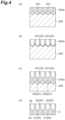
- the substrate may be formed by anodizing a valve metal or silicon.
- the substrate in which the plurality of through-holes are formed can be easily and reliably obtained.
- the conductive layer may be formed of platinum or gold.
- the conductive layer suitable for ionization of the sample can be easily and reliably obtained.
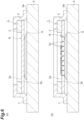
- An ionization method of another aspect of the present disclosure includes: a first process of preparing the sample support body described above; a second process of mounting the sample on a mount surface of a mount portion, and mounting the sample support body on the mount surface such that the second surface faces the sample; and a third process of ionizing components of the sample having moved to the first surface side through the plurality of through-holes by irradiating the first surface with an energy beam while applying a voltage to the conductive layer.
- the ionization method since the aforementioned sample support body is used, signal intensity of the ionized components of the sample can be improved in mass spectrometry.
- a mass spectrometry method of another aspect of the present disclosure includes: the first process, the second process, and the third process of the ionization method described above; and a fourth process of detecting the components ionized in the third process.
- the mass spectrometry method since the aforementioned sample support body is used, signal intensity of the ionized components of the sample can be improved in mass spectrometry.
- a sample support body, an ionization method, and a mass spectrometry method capable of improving signal intensity of components of an ionized sample in mass spectrometry can be provided.
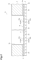
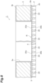
- a sample support body 1 is used for ionization of a sample, and includes a substrate 2, a frame 3, and a conductive layer 4.
- the substrate 2 includes a first surface 2a and a second surface 2b on sides opposite to each other.
- a plurality of through-holes 20 are formed in the substrate 2 in a uniform manner (with uniform distribution).
- Each of the through-holes 20 extends in a thickness direction of the substrate 2 (a direction in which the first surface 2a and the second surface 2b are opposite to each other), and opens on the first surface 2a and the second surface 2b.
- the substrate 2 is formed of, for instance, an insulating material in the shape of a rectangular plate.
- a length of one side of the substrate 2 is, for instance, several centimeters, and a thickness of the substrate 2 is 1 ⁇ m to 50 ⁇ m.
- a width of a second opening 20b on the second surface 2b side is larger than a width of a first opening 20a on the first surface 2a side.
- an outer edge of the second opening 20b in each of the through-holes 20 is located outside of an outer edge of the first opening 20a. That is, when viewed in the thickness direction of the substrate 2, the outer edge of the second opening 20b in each of the through-holes 20 includes the outer edge of the first opening 20a.
- the widths of the first openings 20a are diameters of the first openings 20a in a case where shapes of the first openings 20a are nearly circular shapes when viewed in the thickness direction of the substrate 2, and are diameters (effective diameters) of virtual maximum circles fitted into the shapes in a case where the shapes are other than the nearly circular shapes.
- the widths of the second opening 20b are diameters of the second opening 20b in a case where shapes of the second opening 20b are nearly circular shapes when viewed in the thickness direction of the substrate 2, and are diameters (effective diameters) of virtual maximum circles inscribed in the shapes in a case where the shapes are something other than the nearly circular shapes.
- the widths of the second openings 20b are about twice the widths of the first openings 20a.
- Each of the through-holes 20 includes a first portion 21 on the first opening 20a side, and a second portion 22 on the second opening 20b side.
- the first portion 21 has a columnar shape.
- the second portion 22 has a funnel shape expanding toward the second opening 20b.
- a center line of the first portion 21 and a center line of the second portion 22 are identical to each other.
- a minimum value of the width is 1 nm and a maximum value of the width is 700 nm.
- the outer edge of the second opening 20b is located outside the outer edge of the first opening 20a in each of the plurality of through-holes 20.
- the sample support body 1 when viewed in the thickness direction of the substrate 2, the outer edge of the second opening 20b is located outside the outer edge of the first opening 20a in each of the plurality of through-holes 20.
- each of the plurality of through-holes 20 includes the first portion 21 on the first opening 20a side and the second portion 22 on the second opening 20b side, and the second portion 22 has a funnel shape expanding toward the second opening 20b.
- the sample support body 1 when the sample support body 1 is disposed such that the second surface 2b faces the sample S, components S1 of the sample S move smoothly toward the first surface 2a through the plurality of through-holes 20, and the components S1 of the sample S can be made to stay on the first surface 2a side in an appropriate state.
- the minimum value of the width is 1 nm and the maximum value of the width is 700 nm in each of the plurality of through-holes 20.
- the sample support body 1 when the sample support body 1 is disposed such that the second surface 2b faces the sample S, components S1 of the sample S move smoothly toward the first surface 2a through the plurality of through-holes 20, and the components S1 of the sample S can be made to stay on the first surface 2a side in an appropriate state.
- the conductive layer 4 is formed of Pt or Au.
- the conductive layer 4 suitable for ionization of the sample S can be easily and reliably obtained.
- each of the plurality of through-holes 20 may have a frustum shape expanding toward the second opening 20b.
- the sample support body 1 is disposed such that the second surface 2b faces the sample S, components S1 of the sample S move smoothly toward the first surface 2a through the plurality of through-holes 20, and the components S1 of the sample S can be made to stay on the first surface 2a side in an appropriate state. Further, in this case, strength of the substrate 2 can be improved.
- each of the through-holes 20 is not limited to the foregoing shape, and may be a shape in which the width of the second opening 20b on the second surface 2b side is larger than the width of the first opening 20a on the first surface 2a side (e.g., a shape in which the widths of the through-holes 20 increase continuously or stepwise toward the second opening 20b).
- the outer edge of the second opening 20b is preferably located outside the outer edge of the first opening 20a in each of the plurality of through-holes 20.
- one effective region R is provided on the substrate 2, but a plurality of effective regions R may be provided on the substrate 2.
- the plurality of through-holes 20 need not be formed only in the effective region R, and as in the aforementioned embodiment, for example, the plurality of through-holes 20 may be formed throughout substrate 2. That is, the plurality of through-holes 20 may be formed at least in the effective region R.
- the sample S is disposed such that one sample S corresponds to one effective region R, but the sample S may be disposed such that a plurality of samples S correspond to one effective region R.
- the conductive layer 4 may be provided at least on the first surface 2a. Therefore, the conductive layer 4 may be provided, for instance, on an inner surface of the first portion 21 of each of the through-holes 20 in addition to the first surface 2a. Alternatively, the conductive layer 4 may be provided, for instance, on the second surface 2b of the substrate 2 and on an inner surface of each of the through-holes 20 in addition to the first surface 2a.
- the sample support body 1 may be fixed to the slide glass 6 by a means other than the tape 7 (e.g., a means using an adhesive, a fixing tool, etc.).
- the voltage may be applied to the conductive layer 4 without using the mount surface 6a of the slide glass 6 and the tape 7. In that case, the slide glass 6 and the tape 7 may not have conductivity. Further, the tape 7 may be a part of the sample support body 1.
- the tape 7 may be previously fixed on the first surface 2a side on a circumferential edge of the substrate 2, or be previously fixed on the conductive layer 4 formed on the surface 3b of the frame 3.
- the laser beam irradiation part 13 may irradiate the region corresponding to the effective region R with the laser beam L all at once and the ion detector 15 may detect sample ions S2 while maintaining two-dimensional information of the region. That is, the mass spectrometer 10 may be a projection type mass spectrometer. Further, the aforementioned ionization method can also be used for other measurement such as ion mobility measurement and other experiments.
- the use of the sample support body 1 is not limited to the ionization of the sample S caused by the irradiation of the laser beam L.
- the sample support body 1 may be used for the ionization of the sample S caused by irradiation of an energy beam such as a laser beam, an ion beam, or an electron beam.
- the sample S can be ionized by the irradiation of the energy beam.
- the sample S is not limited to hydrous sample and may be a dry sample.
- the sample support body 1 is mounted on the mount surface 6a such that the second surface 2b faces the sample S, and then, a predetermined solution is dropped to the plurality of through-holes 20 from the first surface 2a side, for example.
- a predetermined solution is dropped to the plurality of through-holes 20 from the first surface 2a side, for example.
- components S1 of the sample S move smoothly toward the first surface 2a through the plurality of through-holes 20, and the components S1 of the sample S can be made to stay on the first surface 2a side in an appropriate state.
- a solution containing the sample S may be placed on the mount surface 6a, and the sample support body 1 may be mounted on the mount surface 5a such that the second surface 2b faces the solution containing the sample S. Also in that case, components S1 of the sample S move smoothly toward the first surface 2a through the plurality of through-holes 20, and the components S1 of the sample S can be made to stay on the first surface 2a side in an appropriate state.
- 1 sample support body
- 2 substrate
- 2a first surface
- 2b second surface
- 4 conductive layer
- 6 slide glass (mount portion)
- 6a mount surface
- 20 through-hole
- 20a first opening
- 20b second opening
- 21 first portion
- 22 second portion
- R effective region
- L laser beam (energy beam)
- S sample
- S1 component.
Landscapes
- Physics & Mathematics (AREA)
- Chemical & Material Sciences (AREA)
- Analytical Chemistry (AREA)
- Health & Medical Sciences (AREA)
- Life Sciences & Earth Sciences (AREA)
- Spectroscopy & Molecular Physics (AREA)
- Optics & Photonics (AREA)
- Pathology (AREA)
- Chemical Kinetics & Catalysis (AREA)
- Biochemistry (AREA)
- General Health & Medical Sciences (AREA)
- General Physics & Mathematics (AREA)
- Immunology (AREA)
- Electrochemistry (AREA)
- Molecular Biology (AREA)
- Engineering & Computer Science (AREA)
- Plasma & Fusion (AREA)
- Toxicology (AREA)
- Other Investigation Or Analysis Of Materials By Electrical Means (AREA)
- Electron Tubes For Measurement (AREA)
Claims (8)
- Probehalterkörper zur Ionisierung einer Probe (S), wobei der Probehalterkörper aufweist:ein Substrat (2) mit einer ersten Oberfläche (2a) und einer zweiten Oberfläche (2b) auf einander gegenüberliegenden Seiten; undeine leitfähige Schicht (4), die zumindest auf der ersten Oberfläche (2a) vorgesehen ist,wobei eine Vielzahl von Durchgangslöchern (20), die sich auf der ersten Oberfläche (2a) und der zweiten Oberfläche (2b) öffnen, in einem wirksamen Bereich (R) des Substrats (2) ausgebildet sind, wobei der wirksame Bereich (R) zum Ionisieren von Komponenten der Probe (S) dient,eine Breite einer zweiten Öffnung (20b) auf der zweiten Oberflächenseite größer ist als eine Breite einer ersten Öffnung (20a) auf der ersten Oberflächenseite in jedem der Vielzahl von Durchgangslöchern (20), so dass Komponenten der Probe (S) aufgrund eines Kapillarphänomens durch die Vielzahl von Durchgangslöchern (20) in Richtung der ersten Oberfläche (2a) wandern, und die Komponenten der Probe (S) aufgrund von Oberflächenspannung auf der ersten Oberflächenseite verbleiben,ein Minimalwert der Breite 1 nm und ein Maximalwert der Breite 700 nm in jedem der Vielzahl von Durchgangslöchern (20) beträgt, undeine Dicke des Substrats 1 µm bis 50 µm beträgt.
- Probehalterkörper nach Anspruch 1,
wobei, in einer Richtung betrachtet, in der die erste Oberfläche (2a) und die zweite Oberfläche (2b) einander gegenüberliegen, eine Außenkante der zweiten Öffnung (20b) außerhalb einer Außenkante der ersten Öffnung (20a) in jedem der Vielzahl von Durchgangslöchern (20) angeordnet ist. - Probehalterkörper nach Anspruch 1 oder 2,wobei jedes der Vielzahl von Durchgangslöchern (20) einen ersten Abschnitt (21) auf der ersten Öffnungsseite und einen zweiten Abschnitt (22) auf der zweiten Öffnungsseite umfasst, undwobei der zweite Abschnitt (22) eine Trichterform aufweist, die sich in Richtung der zweiten Öffnung (20b) erweitert.
- Probehalterkörper gemäß Anspruch 1 oder 2,
wobei jedes der Vielzahl von Durchgangslöchern (20) eine Kegelstumpfform aufweist, die sich zur zweiten Öffnung (20b) hin erweitert. - Probehalterkörper nach einem der Ansprüche 1 bis 4,
wobei das Substrat (2) durch Anodisieren eines Ventilmetalls oder Siliziums gebildet ist. - Probehalterkörper nach einem der Ansprüche 1 bis 5,
wobei die leitfähige Schicht (4) aus Platin oder Gold gebildet ist. - Ionisationsverfahren, aufweisend:einen ersten Prozess des Vorbereitens des Probenhalterkörpers (1) gemäß einem der Ansprüche 1 bis 6;einen zweiten Prozess, bei dem die Probe (S) auf einer Befestigungsfläche (6a) eines Befestigungsabschnitts (6) befestigt wird und der Probehalterkörper (1) so auf der Befestigungsfläche (6a) befestigt wird, dass die zweite Fläche (2b) der Probe (S) zugewandt ist; undeinen dritten Prozess zum Ionisieren von Komponenten der Probe (S), die durch die Vielzahl von Durchgangslöchern (20) zur ersten Oberflächenseite gewandert sind, indem die erste Oberfläche (2a) mit einem Energiestrahl bestrahlt wird, während an die leitfähige Schicht (4) eine Spannung angelegt wird.
- Massenspektrometrieverfahren, umfassend:den ersten Prozess, den zweiten Prozess und den dritten Prozess des Ionisierungsverfahrens gemäß Anspruch 7; undeinen vierten Prozess zum Detektieren der im dritten Prozess ionisierten Komponenten.
Applications Claiming Priority (2)
| Application Number | Priority Date | Filing Date | Title |
|---|---|---|---|
| JP2018021808 | 2018-02-09 | ||
| PCT/JP2019/001114 WO2019155835A1 (ja) | 2018-02-09 | 2019-01-16 | 試料支持体、イオン化法及び質量分析方法 |
Publications (3)
| Publication Number | Publication Date |
|---|---|
| EP3751271A1 EP3751271A1 (de) | 2020-12-16 |
| EP3751271A4 EP3751271A4 (de) | 2021-11-10 |
| EP3751271B1 true EP3751271B1 (de) | 2025-07-02 |
Family
ID=67548088
Family Applications (1)
| Application Number | Title | Priority Date | Filing Date |
|---|---|---|---|
| EP19750624.9A Active EP3751271B1 (de) | 2018-02-09 | 2019-01-16 | Probenträger, ionisationsverfahren und massenspektrometrisches verfahren |
Country Status (5)
| Country | Link |
|---|---|
| US (1) | US11404256B2 (de) |
| EP (1) | EP3751271B1 (de) |
| JP (1) | JP7186187B2 (de) |
| CN (1) | CN111684275A (de) |
| WO (1) | WO2019155835A1 (de) |
Families Citing this family (3)
| Publication number | Priority date | Publication date | Assignee | Title |
|---|---|---|---|---|
| JP7181901B2 (ja) * | 2018-02-09 | 2022-12-01 | 浜松ホトニクス株式会社 | 試料支持体、イオン化法及び質量分析方法 |
| US11189476B2 (en) * | 2018-02-09 | 2021-11-30 | Hamamatsu Photonics K.K. | Sample support, ionization method, and mass spectrometry method |
| JP7449848B2 (ja) * | 2020-12-14 | 2024-03-14 | 浜松ホトニクス株式会社 | 試料支持体、イオン化法及び質量分析方法 |
Family Cites Families (47)
| Publication number | Priority date | Publication date | Assignee | Title |
|---|---|---|---|---|
| DE19628178C1 (de) | 1996-07-12 | 1997-09-18 | Bruker Franzen Analytik Gmbh | Verfahren zum Beladen von Probenträgern für Massenspektrometer |
| DE69738752D1 (de) * | 1996-08-26 | 2008-07-17 | Nippon Telegraph & Telephone | Verfahren zur herstellung poröser, anodisierter aluminiumfilme |
| DE19754978C2 (de) | 1997-12-11 | 2000-07-13 | Bruker Daltonik Gmbh | Probenträger für die MALDI-Massenspektrometrie nebst Verfahren zur Herstellung der Platten und zum Aufbringen der Proben |
| US20020046410A1 (en) | 2000-09-06 | 2002-04-18 | Robert Lanza | Method for generating immune-compatible cells and tissues using nuclear transfer techniques |
| GB9922837D0 (en) * | 1999-09-27 | 1999-11-24 | Ludwig Inst Cancer Res | Modified ion source targets for use in liquid maldi ms |
| JP4361271B2 (ja) * | 2000-10-10 | 2009-11-11 | バイオトローブ・インコーポレイテツド | アッセイ、合成、および保存用の器具、ならびに、その作製、使用、および操作の方法 |
| WO2002097392A2 (en) | 2001-05-25 | 2002-12-05 | Waters Investments Limited | Sample concentration maldi plates for maldi mass spectrometry |
| US6663776B2 (en) | 2001-10-03 | 2003-12-16 | Selee Corporation | High strength SiC filter and method for the manufacture thereof |
| US6707036B2 (en) | 2002-03-21 | 2004-03-16 | Thermo Finnigan Llc | Ionization apparatus and method for mass spectrometer system |
| WO2004051234A1 (ja) * | 2002-11-29 | 2004-06-17 | Nec Corporation | 試料乾燥装置およびこれを用いた質量分析装置、質量分析システム |
| JP4750016B2 (ja) | 2003-02-10 | 2011-08-17 | ウオーターズ・テクノロジーズ・コーポレイシヨン | 質量分析用試料調製プレート |
| US6891156B2 (en) * | 2003-04-30 | 2005-05-10 | Perkin Elmer Instruments Llc | Sample plate for matrix-assisted laser desorption and ionization mass spectrometry |
| CA2467131C (en) | 2003-05-13 | 2013-12-10 | Becton, Dickinson & Company | Method and apparatus for processing biological and chemical samples |
| US7238269B2 (en) * | 2003-07-01 | 2007-07-03 | 3M Innovative Properties Company | Sample processing device with unvented channel |
| SE0302074D0 (sv) * | 2003-07-15 | 2003-07-15 | Simon Ekstroem | Device and method for analysis of samples using a combined sample treatment and sample carrier device |
| US20070092964A1 (en) | 2003-09-03 | 2007-04-26 | Zymoyx, Inc. | Ion detection using a pillar chip |
| US20090314936A1 (en) * | 2004-02-26 | 2009-12-24 | Yoshinao Okuno | Sample target having sample support surface whose face is treated, production method thereof, and mass spectrometer using the sample target |
| JP4576606B2 (ja) * | 2005-01-21 | 2010-11-10 | 独立行政法人産業技術総合研究所 | 質量分析用イオン化基板及び質量分析装置 |
| CN101175546A (zh) * | 2005-04-05 | 2008-05-07 | 蛋白质发现公司 | 用于包括基质辅助激光解吸电离质谱的化学分析中的改进的分析物的富集和分级方法及器件 |
| US8237114B2 (en) | 2005-10-20 | 2012-08-07 | Japan Science & Technology Agency | Sample target used in mass spectrometry, method for producing the same, and mass spectrometer using the sample target |
| JP2007121135A (ja) | 2005-10-28 | 2007-05-17 | National Institutes Of Natural Sciences | 透明導電シートを用いた生体標本サンプルの作製法及び生体組織の直接質量分析法 |
| WO2007097023A1 (ja) | 2006-02-27 | 2007-08-30 | Shimadzu Corporation | 質量分析装置 |
| JP3122331U (ja) * | 2006-03-30 | 2006-06-08 | 株式会社島津製作所 | サンプルプレート及びこれを備えた質量分析装置 |
| JP4732951B2 (ja) * | 2006-05-22 | 2011-07-27 | 株式会社島津製作所 | Maldi用サンプル調製方法及び質量分析方法 |
| US7695978B2 (en) | 2007-01-31 | 2010-04-13 | Burle Technologies, Inc. | MALDI target plate utilizing micro-wells |
| JP4838201B2 (ja) | 2007-06-22 | 2011-12-14 | 財団法人神奈川科学技術アカデミー | 陽極酸化ポーラスアルミナの製造方法 |
| KR100917271B1 (ko) | 2007-10-30 | 2009-09-21 | 대창공업 주식회사 | 금속 용탕 중의 불순물 제거를 위한 다층구조를 가지는필터 |
| JP5301810B2 (ja) | 2007-11-13 | 2013-09-25 | 住友電気工業株式会社 | 陽極酸化アルミナ自立膜およびその製造方法 |
| JP2010071664A (ja) * | 2008-09-16 | 2010-04-02 | Fujifilm Corp | 質量分析用デバイスおよびその作製方法、並びに、そのデバイスを用いたレーザ脱離イオン化質量分析装置および分析方法 |
| KR101563689B1 (ko) * | 2009-03-13 | 2015-11-09 | 삼성전자주식회사 | 튜브 연결용 부속품 및 이를 구비한 미세유동 시스템 |
| JP5632316B2 (ja) * | 2011-03-18 | 2014-11-26 | 株式会社日立ハイテクノロジーズ | 質量分析装置及びそれに用いられるイオン源 |
| US9029813B2 (en) | 2011-05-20 | 2015-05-12 | Asml Netherlands B.V. | Filter for material supply apparatus of an extreme ultraviolet light source |
| CN103295873B (zh) * | 2012-03-01 | 2016-11-02 | 株式会社岛津制作所 | 一种低压下产生分析用离子的方法和装置 |
| WO2013136758A1 (ja) * | 2012-03-15 | 2013-09-19 | パナソニック株式会社 | Led用基板、ledモジュールおよびled電球 |
| JP6006548B2 (ja) | 2012-07-04 | 2016-10-12 | 株式会社 資生堂 | 成分分布可視化装置、成分分布可視化方法、及び成分分布可視化プログラム |
| JP6087357B2 (ja) | 2012-08-01 | 2017-03-01 | 公益財団法人神奈川科学技術アカデミー | アルミナスルーホールメンブレンおよびその製造方法 |
| US9653561B2 (en) | 2013-03-12 | 2017-05-16 | Macronix International Co., Ltd. | Low on resistance semiconductor device |
| JP6269666B2 (ja) * | 2013-06-17 | 2018-01-31 | 株式会社島津製作所 | イオン輸送装置及び該装置を用いた質量分析装置 |
| US9875884B2 (en) * | 2015-02-28 | 2018-01-23 | Agilent Technologies, Inc. | Ambient desorption, ionization, and excitation for spectrometry |
| CN107076705B (zh) | 2015-09-03 | 2019-11-26 | 浜松光子学株式会社 | 表面辅助激光解吸电离法、质量分析方法和质量分析装置 |
| CN106796198B (zh) * | 2015-09-03 | 2020-06-30 | 浜松光子学株式会社 | 试样支撑体和试样支撑体的制造方法 |
| KR102619528B1 (ko) | 2015-12-09 | 2023-12-29 | 삼성전자주식회사 | 포토레지스트 조성물, 패턴 형성 방법 및 반도체 장치의 제조 방법 |
| JP2017114853A (ja) * | 2015-12-18 | 2017-06-29 | 株式会社半導体エネルギー研究所 | 有機金属錯体、発光素子、発光装置、電子機器、および照明装置 |
| EP3418731B1 (de) | 2016-03-18 | 2023-05-03 | Citizen Finedevice Co., Ltd. | Probenträgerplatte und verfahren zur herstellung davon |
| CN106885839B (zh) * | 2017-04-27 | 2019-07-16 | 吉林大学 | 一种通过将分析物富集到尖端提高解吸电离效率的方法 |
| US10562524B2 (en) | 2017-06-29 | 2020-02-18 | Nio Usa, Inc. | Rollover control algorithm |
| US10971345B2 (en) * | 2017-09-21 | 2021-04-06 | Hamamatsu Photonics K.K. | Mass spectrometer and mass spectrometry method |
-
2019
- 2019-01-16 US US16/965,437 patent/US11404256B2/en active Active
- 2019-01-16 WO PCT/JP2019/001114 patent/WO2019155835A1/ja not_active Ceased
- 2019-01-16 JP JP2019570636A patent/JP7186187B2/ja active Active
- 2019-01-16 CN CN201980011586.2A patent/CN111684275A/zh active Pending
- 2019-01-16 EP EP19750624.9A patent/EP3751271B1/de active Active
Also Published As
| Publication number | Publication date |
|---|---|
| EP3751271A1 (de) | 2020-12-16 |
| JPWO2019155835A1 (ja) | 2021-03-11 |
| US20210057198A1 (en) | 2021-02-25 |
| JP7186187B2 (ja) | 2022-12-08 |
| WO2019155835A1 (ja) | 2019-08-15 |
| US11404256B2 (en) | 2022-08-02 |
| EP3751271A4 (de) | 2021-11-10 |
| CN111684275A (zh) | 2020-09-18 |
Similar Documents
| Publication | Publication Date | Title |
|---|---|---|
| US11189474B2 (en) | Sample support, ionization method, and mass spectrometry method | |
| CN111094966B (zh) | 试样支撑体 | |
| JPWO2019058784A1 (ja) | レーザ脱離イオン化法及び質量分析方法 | |
| EP3751271B1 (de) | Probenträger, ionisationsverfahren und massenspektrometrisches verfahren | |
| EP3751270B1 (de) | Probenträgerkörper und herstellungsverfahren für einen probenträgerkörper | |
| US12080536B2 (en) | Sample support, adapter, ionization method and mass spectrometry method | |
| US11189476B2 (en) | Sample support, ionization method, and mass spectrometry method | |
| US11393667B2 (en) | Sample support body and production method for sample support body | |
| JP7233268B2 (ja) | 試料支持体、イオン化方法、及び質量分析方法 | |
| JP7193486B2 (ja) | 試料支持体、及び試料支持体の製造方法 | |
| EP3943927A1 (de) | Probenträger, ionisationsverfahren und massenspektrometrisches verfahren | |
| EP3686589B1 (de) | Verfahren zur laserdesorption/ionisierung und massenspektrometrieverfahren |
Legal Events
| Date | Code | Title | Description |
|---|---|---|---|
| STAA | Information on the status of an ep patent application or granted ep patent |
Free format text: STATUS: THE INTERNATIONAL PUBLICATION HAS BEEN MADE |
|
| PUAI | Public reference made under article 153(3) epc to a published international application that has entered the european phase |
Free format text: ORIGINAL CODE: 0009012 |
|
| STAA | Information on the status of an ep patent application or granted ep patent |
Free format text: STATUS: REQUEST FOR EXAMINATION WAS MADE |
|
| 17P | Request for examination filed |
Effective date: 20200803 |
|
| AK | Designated contracting states |
Kind code of ref document: A1 Designated state(s): AL AT BE BG CH CY CZ DE DK EE ES FI FR GB GR HR HU IE IS IT LI LT LU LV MC MK MT NL NO PL PT RO RS SE SI SK SM TR |
|
| AX | Request for extension of the european patent |
Extension state: BA ME |
|
| DAV | Request for validation of the european patent (deleted) | ||
| DAX | Request for extension of the european patent (deleted) | ||
| REG | Reference to a national code |
Ref legal event code: R079 Ipc: H01J0049040000 Ref country code: DE Ref legal event code: R079 Ref document number: 602019071942 Country of ref document: DE Free format text: PREVIOUS MAIN CLASS: G01N0027620000 Ipc: H01J0049040000 |
|
| A4 | Supplementary search report drawn up and despatched |
Effective date: 20211008 |
|
| RIC1 | Information provided on ipc code assigned before grant |
Ipc: H01J 49/04 20060101AFI20211004BHEP |
|
| STAA | Information on the status of an ep patent application or granted ep patent |
Free format text: STATUS: EXAMINATION IS IN PROGRESS |
|
| 17Q | First examination report despatched |
Effective date: 20231109 |
|
| GRAP | Despatch of communication of intention to grant a patent |
Free format text: ORIGINAL CODE: EPIDOSNIGR1 |
|
| STAA | Information on the status of an ep patent application or granted ep patent |
Free format text: STATUS: GRANT OF PATENT IS INTENDED |
|
| INTG | Intention to grant announced |
Effective date: 20250408 |
|
| GRAS | Grant fee paid |
Free format text: ORIGINAL CODE: EPIDOSNIGR3 |
|
| GRAA | (expected) grant |
Free format text: ORIGINAL CODE: 0009210 |
|
| STAA | Information on the status of an ep patent application or granted ep patent |
Free format text: STATUS: THE PATENT HAS BEEN GRANTED |
|
| AK | Designated contracting states |
Kind code of ref document: B1 Designated state(s): AL AT BE BG CH CY CZ DE DK EE ES FI FR GB GR HR HU IE IS IT LI LT LU LV MC MK MT NL NO PL PT RO RS SE SI SK SM TR |
|
| REG | Reference to a national code |
Ref country code: GB Ref legal event code: FG4D |
|
| REG | Reference to a national code |
Ref country code: CH Ref legal event code: EP |
|
| REG | Reference to a national code |
Ref country code: DE Ref legal event code: R096 Ref document number: 602019071942 Country of ref document: DE |
|
| REG | Reference to a national code |
Ref country code: IE Ref legal event code: FG4D |
|
| P01 | Opt-out of the competence of the unified patent court (upc) registered |
Free format text: CASE NUMBER: UPC_APP_1554_3751271/2025 Effective date: 20250730 |
|
| REG | Reference to a national code |
Ref country code: NL Ref legal event code: MP Effective date: 20250702 |
|
| PG25 | Lapsed in a contracting state [announced via postgrant information from national office to epo] |
Ref country code: PT Free format text: LAPSE BECAUSE OF FAILURE TO SUBMIT A TRANSLATION OF THE DESCRIPTION OR TO PAY THE FEE WITHIN THE PRESCRIBED TIME-LIMIT Effective date: 20251103 |
|
| PG25 | Lapsed in a contracting state [announced via postgrant information from national office to epo] |
Ref country code: NL Free format text: LAPSE BECAUSE OF FAILURE TO SUBMIT A TRANSLATION OF THE DESCRIPTION OR TO PAY THE FEE WITHIN THE PRESCRIBED TIME-LIMIT Effective date: 20250702 |
|
| REG | Reference to a national code |
Ref country code: AT Ref legal event code: MK05 Ref document number: 1810271 Country of ref document: AT Kind code of ref document: T Effective date: 20250702 |
|
| PG25 | Lapsed in a contracting state [announced via postgrant information from national office to epo] |
Ref country code: IS Free format text: LAPSE BECAUSE OF FAILURE TO SUBMIT A TRANSLATION OF THE DESCRIPTION OR TO PAY THE FEE WITHIN THE PRESCRIBED TIME-LIMIT Effective date: 20251102 |
|
| PG25 | Lapsed in a contracting state [announced via postgrant information from national office to epo] |
Ref country code: NO Free format text: LAPSE BECAUSE OF FAILURE TO SUBMIT A TRANSLATION OF THE DESCRIPTION OR TO PAY THE FEE WITHIN THE PRESCRIBED TIME-LIMIT Effective date: 20251002 |
|
| REG | Reference to a national code |
Ref country code: LT Ref legal event code: MG9D |
|
| PG25 | Lapsed in a contracting state [announced via postgrant information from national office to epo] |
Ref country code: AT Free format text: LAPSE BECAUSE OF FAILURE TO SUBMIT A TRANSLATION OF THE DESCRIPTION OR TO PAY THE FEE WITHIN THE PRESCRIBED TIME-LIMIT Effective date: 20250702 |
|
| PG25 | Lapsed in a contracting state [announced via postgrant information from national office to epo] |
Ref country code: FI Free format text: LAPSE BECAUSE OF FAILURE TO SUBMIT A TRANSLATION OF THE DESCRIPTION OR TO PAY THE FEE WITHIN THE PRESCRIBED TIME-LIMIT Effective date: 20250702 |
|
| PG25 | Lapsed in a contracting state [announced via postgrant information from national office to epo] |
Ref country code: HR Free format text: LAPSE BECAUSE OF FAILURE TO SUBMIT A TRANSLATION OF THE DESCRIPTION OR TO PAY THE FEE WITHIN THE PRESCRIBED TIME-LIMIT Effective date: 20250702 |
|
| PG25 | Lapsed in a contracting state [announced via postgrant information from national office to epo] |
Ref country code: GR Free format text: LAPSE BECAUSE OF FAILURE TO SUBMIT A TRANSLATION OF THE DESCRIPTION OR TO PAY THE FEE WITHIN THE PRESCRIBED TIME-LIMIT Effective date: 20251003 |
|
| PG25 | Lapsed in a contracting state [announced via postgrant information from national office to epo] |
Ref country code: SE Free format text: LAPSE BECAUSE OF FAILURE TO SUBMIT A TRANSLATION OF THE DESCRIPTION OR TO PAY THE FEE WITHIN THE PRESCRIBED TIME-LIMIT Effective date: 20250702 Ref country code: CZ Free format text: LAPSE BECAUSE OF FAILURE TO SUBMIT A TRANSLATION OF THE DESCRIPTION OR TO PAY THE FEE WITHIN THE PRESCRIBED TIME-LIMIT Effective date: 20250702 |
|
| PG25 | Lapsed in a contracting state [announced via postgrant information from national office to epo] |
Ref country code: LV Free format text: LAPSE BECAUSE OF FAILURE TO SUBMIT A TRANSLATION OF THE DESCRIPTION OR TO PAY THE FEE WITHIN THE PRESCRIBED TIME-LIMIT Effective date: 20250702 |
|
| PG25 | Lapsed in a contracting state [announced via postgrant information from national office to epo] |
Ref country code: BG Free format text: LAPSE BECAUSE OF FAILURE TO SUBMIT A TRANSLATION OF THE DESCRIPTION OR TO PAY THE FEE WITHIN THE PRESCRIBED TIME-LIMIT Effective date: 20250702 Ref country code: PL Free format text: LAPSE BECAUSE OF FAILURE TO SUBMIT A TRANSLATION OF THE DESCRIPTION OR TO PAY THE FEE WITHIN THE PRESCRIBED TIME-LIMIT Effective date: 20250702 |
|
| PG25 | Lapsed in a contracting state [announced via postgrant information from national office to epo] |
Ref country code: RS Free format text: LAPSE BECAUSE OF FAILURE TO SUBMIT A TRANSLATION OF THE DESCRIPTION OR TO PAY THE FEE WITHIN THE PRESCRIBED TIME-LIMIT Effective date: 20251002 |
|
| PG25 | Lapsed in a contracting state [announced via postgrant information from national office to epo] |
Ref country code: ES Free format text: LAPSE BECAUSE OF FAILURE TO SUBMIT A TRANSLATION OF THE DESCRIPTION OR TO PAY THE FEE WITHIN THE PRESCRIBED TIME-LIMIT Effective date: 20250702 |
|
| PG25 | Lapsed in a contracting state [announced via postgrant information from national office to epo] |
Ref country code: SM Free format text: LAPSE BECAUSE OF FAILURE TO SUBMIT A TRANSLATION OF THE DESCRIPTION OR TO PAY THE FEE WITHIN THE PRESCRIBED TIME-LIMIT Effective date: 20250702 |
|
| PG25 | Lapsed in a contracting state [announced via postgrant information from national office to epo] |
Ref country code: DK Free format text: LAPSE BECAUSE OF FAILURE TO SUBMIT A TRANSLATION OF THE DESCRIPTION OR TO PAY THE FEE WITHIN THE PRESCRIBED TIME-LIMIT Effective date: 20250702 |
|
| PG25 | Lapsed in a contracting state [announced via postgrant information from national office to epo] |
Ref country code: IT Free format text: LAPSE BECAUSE OF FAILURE TO SUBMIT A TRANSLATION OF THE DESCRIPTION OR TO PAY THE FEE WITHIN THE PRESCRIBED TIME-LIMIT Effective date: 20250702 |
|
| PG25 | Lapsed in a contracting state [announced via postgrant information from national office to epo] |
Ref country code: EE Free format text: LAPSE BECAUSE OF FAILURE TO SUBMIT A TRANSLATION OF THE DESCRIPTION OR TO PAY THE FEE WITHIN THE PRESCRIBED TIME-LIMIT Effective date: 20250702 Ref country code: SK Free format text: LAPSE BECAUSE OF FAILURE TO SUBMIT A TRANSLATION OF THE DESCRIPTION OR TO PAY THE FEE WITHIN THE PRESCRIBED TIME-LIMIT Effective date: 20250702 |