EP3749485B1 - Entschichtungseinrichtungen und -verfahren zum entschichten von glastafeln, vorzugsweise verbundglastafeln - Google Patents
Entschichtungseinrichtungen und -verfahren zum entschichten von glastafeln, vorzugsweise verbundglastafeln Download PDFInfo
- Publication number
- EP3749485B1 EP3749485B1 EP19710616.4A EP19710616A EP3749485B1 EP 3749485 B1 EP3749485 B1 EP 3749485B1 EP 19710616 A EP19710616 A EP 19710616A EP 3749485 B1 EP3749485 B1 EP 3749485B1
- Authority
- EP
- European Patent Office
- Prior art keywords
- laser
- decoating
- film strip
- glass
- protective film
- Prior art date
- Legal status (The legal status is an assumption and is not a legal conclusion. Google has not performed a legal analysis and makes no representation as to the accuracy of the status listed.)
- Active
Links
Images


Classifications
-
- B—PERFORMING OPERATIONS; TRANSPORTING
- B23—MACHINE TOOLS; METAL-WORKING NOT OTHERWISE PROVIDED FOR
- B23K—SOLDERING OR UNSOLDERING; WELDING; CLADDING OR PLATING BY SOLDERING OR WELDING; CUTTING BY APPLYING HEAT LOCALLY, e.g. FLAME CUTTING; WORKING BY LASER BEAM
- B23K26/00—Working by laser beam, e.g. welding, cutting or boring
- B23K26/36—Removing material
- B23K26/38—Removing material by boring or cutting
-
- B—PERFORMING OPERATIONS; TRANSPORTING
- B23—MACHINE TOOLS; METAL-WORKING NOT OTHERWISE PROVIDED FOR
- B23K—SOLDERING OR UNSOLDERING; WELDING; CLADDING OR PLATING BY SOLDERING OR WELDING; CUTTING BY APPLYING HEAT LOCALLY, e.g. FLAME CUTTING; WORKING BY LASER BEAM
- B23K26/00—Working by laser beam, e.g. welding, cutting or boring
- B23K26/0006—Working by laser beam, e.g. welding, cutting or boring taking account of the properties of the material involved
-
- B—PERFORMING OPERATIONS; TRANSPORTING
- B23—MACHINE TOOLS; METAL-WORKING NOT OTHERWISE PROVIDED FOR
- B23K—SOLDERING OR UNSOLDERING; WELDING; CLADDING OR PLATING BY SOLDERING OR WELDING; CUTTING BY APPLYING HEAT LOCALLY, e.g. FLAME CUTTING; WORKING BY LASER BEAM
- B23K26/00—Working by laser beam, e.g. welding, cutting or boring
- B23K26/0093—Working by laser beam, e.g. welding, cutting or boring combined with mechanical machining or metal-working covered by other subclasses than B23K
-
- B—PERFORMING OPERATIONS; TRANSPORTING
- B23—MACHINE TOOLS; METAL-WORKING NOT OTHERWISE PROVIDED FOR
- B23K—SOLDERING OR UNSOLDERING; WELDING; CLADDING OR PLATING BY SOLDERING OR WELDING; CUTTING BY APPLYING HEAT LOCALLY, e.g. FLAME CUTTING; WORKING BY LASER BEAM
- B23K26/00—Working by laser beam, e.g. welding, cutting or boring
- B23K26/08—Devices involving relative movement between laser beam and workpiece
- B23K26/082—Scanning systems, i.e. devices involving movement of the laser beam relative to the laser head
-
- B—PERFORMING OPERATIONS; TRANSPORTING
- B23—MACHINE TOOLS; METAL-WORKING NOT OTHERWISE PROVIDED FOR
- B23K—SOLDERING OR UNSOLDERING; WELDING; CLADDING OR PLATING BY SOLDERING OR WELDING; CUTTING BY APPLYING HEAT LOCALLY, e.g. FLAME CUTTING; WORKING BY LASER BEAM
- B23K26/00—Working by laser beam, e.g. welding, cutting or boring
- B23K26/08—Devices involving relative movement between laser beam and workpiece
- B23K26/0869—Devices involving movement of the laser head in at least one axial direction
- B23K26/0876—Devices involving movement of the laser head in at least one axial direction in at least two axial directions
-
- B—PERFORMING OPERATIONS; TRANSPORTING
- B23—MACHINE TOOLS; METAL-WORKING NOT OTHERWISE PROVIDED FOR
- B23K—SOLDERING OR UNSOLDERING; WELDING; CLADDING OR PLATING BY SOLDERING OR WELDING; CUTTING BY APPLYING HEAT LOCALLY, e.g. FLAME CUTTING; WORKING BY LASER BEAM
- B23K26/00—Working by laser beam, e.g. welding, cutting or boring
- B23K26/352—Working by laser beam, e.g. welding, cutting or boring for surface treatment
- B23K26/359—Working by laser beam, e.g. welding, cutting or boring for surface treatment by providing a line or line pattern, e.g. a dotted break initiation line
-
- B—PERFORMING OPERATIONS; TRANSPORTING
- B23—MACHINE TOOLS; METAL-WORKING NOT OTHERWISE PROVIDED FOR
- B23K—SOLDERING OR UNSOLDERING; WELDING; CLADDING OR PLATING BY SOLDERING OR WELDING; CUTTING BY APPLYING HEAT LOCALLY, e.g. FLAME CUTTING; WORKING BY LASER BEAM
- B23K26/00—Working by laser beam, e.g. welding, cutting or boring
- B23K26/36—Removing material
- B23K26/362—Laser etching
- B23K26/364—Laser etching for making a groove or trench, e.g. for scribing a break initiation groove
-
- B—PERFORMING OPERATIONS; TRANSPORTING
- B23—MACHINE TOOLS; METAL-WORKING NOT OTHERWISE PROVIDED FOR
- B23K—SOLDERING OR UNSOLDERING; WELDING; CLADDING OR PLATING BY SOLDERING OR WELDING; CUTTING BY APPLYING HEAT LOCALLY, e.g. FLAME CUTTING; WORKING BY LASER BEAM
- B23K26/00—Working by laser beam, e.g. welding, cutting or boring
- B23K26/36—Removing material
- B23K26/40—Removing material taking account of the properties of the material involved
- B23K26/402—Removing material taking account of the properties of the material involved involving non-metallic material, e.g. isolators
-
- B—PERFORMING OPERATIONS; TRANSPORTING
- B23—MACHINE TOOLS; METAL-WORKING NOT OTHERWISE PROVIDED FOR
- B23K—SOLDERING OR UNSOLDERING; WELDING; CLADDING OR PLATING BY SOLDERING OR WELDING; CUTTING BY APPLYING HEAT LOCALLY, e.g. FLAME CUTTING; WORKING BY LASER BEAM
- B23K37/00—Auxiliary devices or processes, not specially adapted for a procedure covered by only one of the other main groups of this subclass
- B23K37/02—Carriages for supporting the welding or cutting element
- B23K37/0211—Carriages for supporting the welding or cutting element travelling on a guide member, e.g. rail, track
- B23K37/0235—Carriages for supporting the welding or cutting element travelling on a guide member, e.g. rail, track the guide member forming part of a portal
-
- B—PERFORMING OPERATIONS; TRANSPORTING
- B23—MACHINE TOOLS; METAL-WORKING NOT OTHERWISE PROVIDED FOR
- B23K—SOLDERING OR UNSOLDERING; WELDING; CLADDING OR PLATING BY SOLDERING OR WELDING; CUTTING BY APPLYING HEAT LOCALLY, e.g. FLAME CUTTING; WORKING BY LASER BEAM
- B23K37/00—Auxiliary devices or processes, not specially adapted for a procedure covered by only one of the other main groups of this subclass
- B23K37/04—Auxiliary devices or processes, not specially adapted for a procedure covered by only one of the other main groups of this subclass for holding or positioning work
- B23K37/0408—Auxiliary devices or processes, not specially adapted for a procedure covered by only one of the other main groups of this subclass for holding or positioning work for planar work
-
- B—PERFORMING OPERATIONS; TRANSPORTING
- B24—GRINDING; POLISHING
- B24B—MACHINES, DEVICES, OR PROCESSES FOR GRINDING OR POLISHING; DRESSING OR CONDITIONING OF ABRADING SURFACES; FEEDING OF GRINDING, POLISHING, OR LAPPING AGENTS
- B24B7/00—Machines or devices designed for grinding plane surfaces on work, including polishing plane glass surfaces; Accessories therefor
- B24B7/10—Single-purpose machines or devices
- B24B7/19—Single-purpose machines or devices for grinding plane decorative patterns
-
- B—PERFORMING OPERATIONS; TRANSPORTING
- B24—GRINDING; POLISHING
- B24B—MACHINES, DEVICES, OR PROCESSES FOR GRINDING OR POLISHING; DRESSING OR CONDITIONING OF ABRADING SURFACES; FEEDING OF GRINDING, POLISHING, OR LAPPING AGENTS
- B24B7/00—Machines or devices designed for grinding plane surfaces on work, including polishing plane glass surfaces; Accessories therefor
- B24B7/20—Machines or devices designed for grinding plane surfaces on work, including polishing plane glass surfaces; Accessories therefor characterised by a special design with respect to properties of the material of non-metallic articles to be ground
- B24B7/22—Machines or devices designed for grinding plane surfaces on work, including polishing plane glass surfaces; Accessories therefor characterised by a special design with respect to properties of the material of non-metallic articles to be ground for grinding inorganic material, e.g. stone, ceramics, porcelain
- B24B7/24—Machines or devices designed for grinding plane surfaces on work, including polishing plane glass surfaces; Accessories therefor characterised by a special design with respect to properties of the material of non-metallic articles to be ground for grinding inorganic material, e.g. stone, ceramics, porcelain for grinding or polishing glass
- B24B7/242—Machines or devices designed for grinding plane surfaces on work, including polishing plane glass surfaces; Accessories therefor characterised by a special design with respect to properties of the material of non-metallic articles to be ground for grinding inorganic material, e.g. stone, ceramics, porcelain for grinding or polishing glass for plate glass
-
- B—PERFORMING OPERATIONS; TRANSPORTING
- B24—GRINDING; POLISHING
- B24B—MACHINES, DEVICES, OR PROCESSES FOR GRINDING OR POLISHING; DRESSING OR CONDITIONING OF ABRADING SURFACES; FEEDING OF GRINDING, POLISHING, OR LAPPING AGENTS
- B24B7/00—Machines or devices designed for grinding plane surfaces on work, including polishing plane glass surfaces; Accessories therefor
- B24B7/20—Machines or devices designed for grinding plane surfaces on work, including polishing plane glass surfaces; Accessories therefor characterised by a special design with respect to properties of the material of non-metallic articles to be ground
- B24B7/22—Machines or devices designed for grinding plane surfaces on work, including polishing plane glass surfaces; Accessories therefor characterised by a special design with respect to properties of the material of non-metallic articles to be ground for grinding inorganic material, e.g. stone, ceramics, porcelain
- B24B7/24—Machines or devices designed for grinding plane surfaces on work, including polishing plane glass surfaces; Accessories therefor characterised by a special design with respect to properties of the material of non-metallic articles to be ground for grinding inorganic material, e.g. stone, ceramics, porcelain for grinding or polishing glass
- B24B7/247—Machines or devices designed for grinding plane surfaces on work, including polishing plane glass surfaces; Accessories therefor characterised by a special design with respect to properties of the material of non-metallic articles to be ground for grinding inorganic material, e.g. stone, ceramics, porcelain for grinding or polishing glass using reciprocating grinding tools
-
- B—PERFORMING OPERATIONS; TRANSPORTING
- B24—GRINDING; POLISHING
- B24B—MACHINES, DEVICES, OR PROCESSES FOR GRINDING OR POLISHING; DRESSING OR CONDITIONING OF ABRADING SURFACES; FEEDING OF GRINDING, POLISHING, OR LAPPING AGENTS
- B24B9/00—Machines or devices designed for grinding edges or bevels on work or for removing burrs; Accessories therefor
- B24B9/02—Machines or devices designed for grinding edges or bevels on work or for removing burrs; Accessories therefor characterised by a special design with respect to properties of materials specific to articles to be ground
- B24B9/06—Machines or devices designed for grinding edges or bevels on work or for removing burrs; Accessories therefor characterised by a special design with respect to properties of materials specific to articles to be ground of non-metallic inorganic material, e.g. stone, ceramics, porcelain
- B24B9/08—Machines or devices designed for grinding edges or bevels on work or for removing burrs; Accessories therefor characterised by a special design with respect to properties of materials specific to articles to be ground of non-metallic inorganic material, e.g. stone, ceramics, porcelain of glass
- B24B9/10—Machines or devices designed for grinding edges or bevels on work or for removing burrs; Accessories therefor characterised by a special design with respect to properties of materials specific to articles to be ground of non-metallic inorganic material, e.g. stone, ceramics, porcelain of glass of plate glass
-
- B—PERFORMING OPERATIONS; TRANSPORTING
- B32—LAYERED PRODUCTS
- B32B—LAYERED PRODUCTS, i.e. PRODUCTS BUILT-UP OF STRATA OF FLAT OR NON-FLAT, e.g. CELLULAR OR HONEYCOMB, FORM
- B32B17/00—Layered products essentially comprising sheet glass, or glass, slag, or like fibres
- B32B17/06—Layered products essentially comprising sheet glass, or glass, slag, or like fibres comprising glass as the main or only constituent of a layer, next to another layer of a specific material
- B32B17/10—Layered products essentially comprising sheet glass, or glass, slag, or like fibres comprising glass as the main or only constituent of a layer, next to another layer of a specific material of synthetic resin
- B32B17/10005—Layered products essentially comprising sheet glass, or glass, slag, or like fibres comprising glass as the main or only constituent of a layer, next to another layer of a specific material of synthetic resin laminated safety glass or glazing
- B32B17/10807—Making laminated safety glass or glazing; Apparatus therefor
- B32B17/1099—After-treatment of the layered product, e.g. cooling
-
- C—CHEMISTRY; METALLURGY
- C03—GLASS; MINERAL OR SLAG WOOL
- C03C—CHEMICAL COMPOSITION OF GLASSES, GLAZES OR VITREOUS ENAMELS; SURFACE TREATMENT OF GLASS; SURFACE TREATMENT OF FIBRES OR FILAMENTS MADE FROM GLASS, MINERALS OR SLAGS; JOINING GLASS TO GLASS OR OTHER MATERIALS
- C03C17/00—Surface treatment of glass, not in the form of fibres or filaments, by coating
- C03C17/001—General methods for coating; Devices therefor
- C03C17/002—General methods for coating; Devices therefor for flat glass, e.g. float glass
-
- B—PERFORMING OPERATIONS; TRANSPORTING
- B23—MACHINE TOOLS; METAL-WORKING NOT OTHERWISE PROVIDED FOR
- B23K—SOLDERING OR UNSOLDERING; WELDING; CLADDING OR PLATING BY SOLDERING OR WELDING; CUTTING BY APPLYING HEAT LOCALLY, e.g. FLAME CUTTING; WORKING BY LASER BEAM
- B23K2101/00—Articles made by soldering, welding or cutting
- B23K2101/18—Sheet panels
-
- B—PERFORMING OPERATIONS; TRANSPORTING
- B23—MACHINE TOOLS; METAL-WORKING NOT OTHERWISE PROVIDED FOR
- B23K—SOLDERING OR UNSOLDERING; WELDING; CLADDING OR PLATING BY SOLDERING OR WELDING; CUTTING BY APPLYING HEAT LOCALLY, e.g. FLAME CUTTING; WORKING BY LASER BEAM
- B23K2101/00—Articles made by soldering, welding or cutting
- B23K2101/34—Coated articles ; Surface treated articles
-
- B—PERFORMING OPERATIONS; TRANSPORTING
- B23—MACHINE TOOLS; METAL-WORKING NOT OTHERWISE PROVIDED FOR
- B23K—SOLDERING OR UNSOLDERING; WELDING; CLADDING OR PLATING BY SOLDERING OR WELDING; CUTTING BY APPLYING HEAT LOCALLY, e.g. FLAME CUTTING; WORKING BY LASER BEAM
- B23K2103/00—Materials to be soldered, welded or cut
- B23K2103/30—Organic materials
- B23K2103/42—Plastics other than composite materials
-
- B—PERFORMING OPERATIONS; TRANSPORTING
- B23—MACHINE TOOLS; METAL-WORKING NOT OTHERWISE PROVIDED FOR
- B23K—SOLDERING OR UNSOLDERING; WELDING; CLADDING OR PLATING BY SOLDERING OR WELDING; CUTTING BY APPLYING HEAT LOCALLY, e.g. FLAME CUTTING; WORKING BY LASER BEAM
- B23K2103/00—Materials to be soldered, welded or cut
- B23K2103/50—Inorganic materials other than metals or composite materials
- B23K2103/54—Glass
-
- C—CHEMISTRY; METALLURGY
- C03—GLASS; MINERAL OR SLAG WOOL
- C03C—CHEMICAL COMPOSITION OF GLASSES, GLAZES OR VITREOUS ENAMELS; SURFACE TREATMENT OF GLASS; SURFACE TREATMENT OF FIBRES OR FILAMENTS MADE FROM GLASS, MINERALS OR SLAGS; JOINING GLASS TO GLASS OR OTHER MATERIALS
- C03C2218/00—Methods for coating glass
- C03C2218/30—Aspects of methods for coating glass not covered above
- C03C2218/32—After-treatment
- C03C2218/328—Partly or completely removing a coating
-
- C—CHEMISTRY; METALLURGY
- C03—GLASS; MINERAL OR SLAG WOOL
- C03C—CHEMICAL COMPOSITION OF GLASSES, GLAZES OR VITREOUS ENAMELS; SURFACE TREATMENT OF GLASS; SURFACE TREATMENT OF FIBRES OR FILAMENTS MADE FROM GLASS, MINERALS OR SLAGS; JOINING GLASS TO GLASS OR OTHER MATERIALS
- C03C2218/00—Methods for coating glass
- C03C2218/30—Aspects of methods for coating glass not covered above
- C03C2218/355—Temporary coating
Definitions
- the present invention relates to a decoating method for edge decoating of glass panels, preferably laminated glass panels, and to a use of a decoating device therefor.
- the individual functional layers are preferably applied to flat glass panels of the maximum commercially available size (6,100 mm x 3,250 mm). Individual panes are then cut from these large-area coated flat glass panels as required, which are then further processed into functional units.
- These functional units can be, for example, insulating glass units, with the edges of the individual panes being bonded with, for example, spacers. Edge bonding adhesives are used for this edge bonding, although the edge bonding adhesives are designed exclusively for direct bonding to glass surfaces and not to the functional layers.
- the flat glass panels must therefore be stripped in the area of the bond, with the stripping width being, for example, around 10 mm. Without stripping, reliable adhesion of the edge bonding adhesive cannot be guaranteed. This process is known as edge stripping.
- edge stripping is carried out along the glass panel edges in a single stripping width.
- stripping is carried out on both sides next to the later cutting, scoring or dividing line in a double stripping width.
- stripping can be carried out along the glass panel edges in a single stripping width - provided the glass panel is of the appropriate size and the glass panel edges are of the right quality.
- the stripping marks created are therefore twice as wide as in the area of the glass panel edges.
- one disadvantage is that the sharp edges can be worn down heavily and asymmetrically by driving over the stripping tools.
- the functional layers are removed using mechanical methods such as grinding tools or sandblasting. However, it can also be done using gas burners.
- German utility model DE 20 2013 104 834 U1 relates to a table for processing non-metallic, transparent materials by laser radiation, in particular for removing metallic coatings, for example low-emission coatings, and other coatings, from glass.
- the EP 1 864 950 A1 , the WO 2016/096435 A1 and the DE 10 2007 015 767 A1 each disclose the removal of layers from glass substrates (flat glass, solar cells) using a laser.
- the material to be removed is the functional layer.
- a removable protective film temporary protective film
- a polymer protective layer e.g. EasyPro ® from St. Gobain
- the polymer protective layer is applied by spraying, for example, and cannot be removed, but is firmly bonded to the respective surface. However, it burns off easily and without residue during tempering in the oven.
- the protective film or polymer protective layer For further processing of the glass panels, e.g. insulating glass production, the protective film or polymer protective layer must of course be removed at least at the edge areas, analogous to the functional layers.
- the removal of the protective film or polymer protective layer is currently carried out mechanically using a grinding tool, in particular a grinding wheel. If the glass panel has a functional coating, the protective film or polymer protective layer and the functional coating are ground off in one operation.
- the protective film is first cut with a double knife and then removed by suction, and in a second step the functional layers are removed.
- the functional layer(s) are removed mechanically by grinding.
- the US 2013/0140291 A1 discloses a device for cutting glass panes.
- the device has a laser beam generating device and a cutting device with a cutting wheel.
- To cut the glass pane grooves are first made in the surface of the glass pane using the laser beam generating device. The glass is then cut using the cutting wheel.
- the WO 2016/096435 A1 discloses that a functional coating is removed by means of a decoating tool that generates a laser beam.
- the decoating tool can also be a grinding wheel or another suitable tool.
- the WO 2016/096435 A1 that the device can have a cutting tool with a cutting wheel or a diamond needle or a laser. The cutting tool cuts or scores the glass sheet.
- the object of the present invention is therefore to provide an edge stripping method for removing the protective film from glass panels, preferably from laminated glass panels, wherein the stripping should be simple, fast, safe and cost-effective.
- Another object of the invention is the use of a decoating device for carrying out the decoating process.
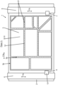
- a cutting and decoating station 1 ( Fig. 1 ) preferably has a support table 2 for receiving a glass sheet 3, a first travel bridge 4, a second travel bridge 5, a cutting device 6 and a decoating device 7 used according to the invention.
- the glass panel 3 ( Fig. 2 ) has a first and second glass panel surface 3a;b as well as a surrounding glass panel edge 3c.
- the glass panel 3 can be, for example, a single glass pane ( Fig. 2 ) or a laminated glass panel made up of several glass panes connected to one another. Furthermore, it is preferably a raw glass panel. However, it can also be a cut glass panel.
- the glass panel 3 has a superficial functional coating 8 on at least one of its two glass surfaces 3a;b.
- the functional coating 8 can have one or more individual functional layers. If there are several functional layers, this is a functional layer laminate.
- the functional layers change certain properties of the glass panel 3 or give it certain functions. The functions can be, for example, heat protection, sun protection or heating.
- the individual functional layers are preferably metallic layers, e.g. low-emission layers.
- the functional coating 8 preferably has a thickness of 1 ⁇ ⁇ m.
- the protective coating 9 is completely removed before the final use of the glass panel 3. It is therefore not permanently present.
- the protective film 10 is peeled off.
- a functional coating 8, on the other hand, is permanently present at least in some areas.
- the protective film 10 is preferably made of plastic, preferably polyvinyl chloride (PVC), and can be removed from the glass panel surface 3a;b.
- PVC polyvinyl chloride
- the protective film 10 preferably has a thickness of 20 to 100 ⁇ m.
- the two travel bridges 4;5 span the support table 2 on the top and/or bottom and can each be moved back and forth over the glass panel 3 in a first travel direction 11a.
- Appropriate drive means are available for this purpose.
- the first travel direction 11a is parallel to a glass panel plane or to the two glass panel surfaces 3a;b.
- the cutting device 6 is used in a manner known per se for cutting or scoring the glass panel surface(s) 3a;b along predetermined scoring or dividing lines 12. If the glass panel 3 is a single pane of glass, only one of the two glass panel surfaces 3a;b is scored.
- the cutting device 6 has a cutting head 13 with a scoring tool, preferably a cutting wheel, in a manner known per se.
- the cutting head 13 is mounted on the first travel bridge 4 so that it can be moved in a second travel direction 11b in a manner known per se. Appropriate drive means are available for this purpose.
- the second travel direction 11b is perpendicular to the first travel direction 11a and also parallel to a glass panel plane or to the two glass panel surfaces 3a;b.
- the cutting wheel can be rotated freely or by a drive about a horizontal axis of rotation that is parallel to the glass panel plane or to the two glass panel surfaces 3a;b.
- the cutting wheel can be rotated freely or by a drive about a vertical axis of rotation that is perpendicular to the glass panel plane or to the two glass panel surfaces 3a;b. This allows any cutting contours to be created in a manner known per se.
- both glass panel surfaces 3a;b are scored in a manner known per se, preferably simultaneously.
- the glass panel 3 is then scored on the top and bottom, preferably simultaneously.
- two cutting heads 13 arranged one above the other are provided.
- the decoating device 7 used according to the invention serves to remove the protective coating 9 and the functional coating 8 arranged underneath.
- it has a laser beam generating device 14 for Generation of a laser beam 15 and a grinding head 16.
- the decoating device 7 is mounted on the second travel bridge 5 so that it can move in the second travel direction 11b. Appropriate drive means are available for this purpose.
- the laser beam generating device 14 is used to cut the protective film 10, which will be discussed in more detail below. To do this, the laser beam generating device 14 generates the laser beam 15 directed at the glass surface 3a.
- the laser beam generating device 14 has a laser radiation source and associated optics.
- the laser beam 15 can be pivoted or deflected from a starting position in which it is aligned vertically.
- the laser radiation source preferably generates a laser beam 15 whose wavelength is in the infrared range.
- the wavelength of the laser beam 15 is preferably 1 to 19 ⁇ m, preferably 9 to 11 ⁇ m.
- the laser radiation source preferably generates a laser beam 15 whose laser power is ⁇ 200 W, preferably ⁇ 100 W, and/or ⁇ 5 W, preferably ⁇ 10 W.
- the grinding head 16 serves to remove the cut protective film 10 and/or to remove the functional coating, which will be discussed in more detail below.
- the grinding head 16 has at least one grinding tool, preferably at least one grinding wheel 17, in a manner known per se.
- the grinding wheel 17 can be freely or drivenly rotated about a horizontal axis of rotation that is parallel to the glass sheet plane or to the two glass sheet surfaces 3a;b. In addition, the grinding wheel 17 can be freely or drivenly rotated about a vertical axis of rotation that is perpendicular to the glass sheet plane or to the two glass sheet surfaces 3a;b. In this way, in combination with the movement of the decoating device 7 along the second travel bridge 5, any decoating contours can be produced in a manner known per se.
- the grinding head 16 has two grinding wheels (not shown) according to the DE 196 322 40 A1
- the first grinding wheel has a thickness of a single stripping width and the second grinding wheel has a thickness of a double stripping width.
- a film strip 18 of the protective film 10 to be removed is first cut out of the protective film 10 by means of the laser beam 15 and at the same time divided into individual film strip sections 19 ( Fig. 3 ).
- the individual film strip sections 19 remain adhered to the glass panel 3. This means that along the later separation or scoring lines 12 or in a longitudinal direction of the film strip 18 to be removed, there are several film strip sections 19 arranged one behind the other, which are not connected to one another and each adhere to the glass panel 3.
- the film strip 18 and the film strip sections 19 are cut out by introducing burn marks or laser marks 20a;b into the protective film 10. In the area of the laser marks 20a;b, the protective film 10 is completely removed, in particular evaporated or burned.
- the laser marks 20a;b surround the film strip sections 19. They thus form the outline or contour of the film strip sections 19.
- the movement of the laser beam 15 is carried out by means of the optics of the laser beam generating device 14 and by movement of the decoating device 7 along the travel bridge 5 and movement of the travel bridge 5.
- the optics of the laser generating device 14 are in fact capable of two adjustable mirrors (scan optics) to move the laser beam 15 in an area of e.g. 100 mm x 100 mm (scan field).
- the grinding wheel 17 After the film strip 18 has been cut out and divided into the individual film strip sections 19, these are ground down using the grinding wheel 17 in a manner known per se.
- the functional coating 8 is also ground down at the same time.
- the grinding head 13 together with the grinding wheel 17 is moved in a manner known per se in the second travel direction 11b along the second travel bridge 5.
- the second travel bridge 5 is moved in the first travel direction 11a.
- the grinding wheel 17 is rotated on the one hand about its wheel rotation axis and, if necessary, pivoted about its vertical axis.
- the glass panel 3 After grinding, the glass panel 3 has stripping marks 21 on the processed glass panel surface 3a.
- the stripping marks 21 extend along the subsequent scoring or separating line 12 and on both sides next to it.
- the scoring or separating line 12 is arranged in the middle of the stripping mark 21. The glass panel is thus stripped in double the stripping width on both sides next to the subsequent scoring or separating line 12.
- the decoating is preferably carried out along the glass panel edges 3c - if the final dimensions of the glass panel 3 are appropriate and the quality of the glass panel edges 3c is sufficient - in a single decoating width.
- the protective film 10 does not roll up during grinding, even at higher feed speeds.
- the individual removed film strip sections 19 can be easily vacuumed away. without the suction becoming clogged or film residues remaining on the glass panel 3.
- the decoating method according to the invention ensures fast, clean and safe decoating.
- laser tracks 20a are generated that are transverse or perpendicular to the longitudinal direction of the film strip 18 to be removed and laser tracks 20b that are parallel to the longitudinal direction of the film strip 18 to be removed.
- the film strip sections 19 are already cut out of the protective film 10 or separated from the rest of the protective film 10 before grinding.
- the laser tracks 20a do not have to be perpendicular to the longitudinal direction of the film strip 18 to be removed, but only at an angle to it.
- the laser tracks 20a;b do not have to be straight either.
- the laser tracks 20a are introduced in such a way that the film strip 18 is removed in the form of individual film strip sections 19 separated from one another by the laser tracks 20a.
- the laser tracks 20a;b are not produced as completely continuous lines, i.e. the protective film 10 is not completely removed in the area of the laser tracks 20a,b, but the protective film 10 is only perforated in the area of the laser tracks 20a;b. During perforation, the protective film 10 is provided with holes at preferably uniform intervals.
- the separating or scoring lines 12 are then created by means of the cutting head 13 and then the glass sheet 3 is broken into individual glass sheet cuts along the scoring or separating lines 12 in a manner known per se.
- the cutting device 6 is separated from the decoating device 7, i.e. is arranged in a different station.
- the grinding head 16 and the laser beam generating device 14 can also be decoupled from one another. This means that they can be moved separately from one another and/or can also be attached to different travel bridges.
- contours can also be created by moving the decoating device 7 on a stationary bridge and moving the glass panel during the decoating process. It is only important that the decoating device 7 including the grinding wheel 17 and/or laser beam 15 and the glass panel 3 carry out corresponding relative movements to one another. The same applies to the cutting process.
- the glass panels also have a protective film and, if applicable, a functional coating on both glass panel surfaces, the coating is removed either for both glass panel surfaces simultaneously or one after the other.
Landscapes
- Engineering & Computer Science (AREA)
- Physics & Mathematics (AREA)
- Optics & Photonics (AREA)
- Mechanical Engineering (AREA)
- Plasma & Fusion (AREA)
- Chemical & Material Sciences (AREA)
- Ceramic Engineering (AREA)
- Inorganic Chemistry (AREA)
- Organic Chemistry (AREA)
- Materials Engineering (AREA)
- Geochemistry & Mineralogy (AREA)
- General Chemical & Material Sciences (AREA)
- Chemical Kinetics & Catalysis (AREA)
- Life Sciences & Earth Sciences (AREA)
- Re-Forming, After-Treatment, Cutting And Transporting Of Glass Products (AREA)
- Laser Beam Processing (AREA)
- Surface Treatment Of Glass (AREA)
- Joining Of Glass To Other Materials (AREA)
Description
- Die vorliegende Erfindung betrifft ein Entschichtungsverfahren zum Randentschichten von Glastafeln, vorzugsweise Verbundglastafeln, sowie eine Verwendung einer Entschichtungseinrichtung hierfür.
- Als Flachglas wird jedes Glas in Form von Scheiben bzw. Tafeln bezeichnet, unabhängig vom angewandten Herstellungsverfahren. Um Flachglastafeln mit Filter-, Spiegel-, Heizfunktionen oder sonstigen Funktionen zu versehen, werden die unterschiedlichsten, ein- oder mehrlagigen Funktionsbeschichtungen auf die Flachglastafeln aufgebracht. Die Funktionen können dabei z.B. Wärmeschutz, Sonnenschutz, oder Beheizung sein. Bei den einzelnen Funktionsschichten handelt es sich in der Regel um metallische Schichten. Beispielsweise handelt es sich um Niedrigemissionsschichten oder elektrische Heizschichten. Zwischen den einzelnen metallischen Funktionsschichten einer Funktionsbeschichtung können eine oder mehrere dielektrische (Funktions)schichten, z.B. aus einem Oxid, wie Aluminiumoxid, angeordnet sein.
- Die Aufbringung der einzelnen Funktionsschichten erfolgt vorzugsweise auf Flachglasrohtafeln maximaler handelsüblicher Größe (6.100 mm x 3.250 mm). Aus diesen großflächig beschichteten Flachglasrohtafeln werden anschließend nach Bedarf Einzelscheiben geschnitten, die dann zu Funktionseinheiten weiterverarbeitet werden. Diese Funktionseinheiten können z. B. Isolierglaseinheiten sein, wobei die Scheibenränder der Einzelscheiben mit z. B. Abstandhaltereinrichtungen verklebt werden. Für diesen Randverbund werden Randverbundkleber verwendet, wobei die Randverbundkleber ausschließlich für den direkten Verbund mit Glasoberflächen und nicht mit den Funktionsschichten ausgelegt sind. Die Flachglasrohtafeln müssen deshalb im Bereich der Verklebung entschichtet werden, wobei die Entschichtungsbreite z. B. etwa 10 mm beträgt. Ohne Entschichtung ist eine zuverlässige Haftung des Randverbundklebers nicht gewährleistet. Diesen Vorgang bezeichnet man als Randentschichtung.
- Die Randentschichtung erfolgt dabei entlang der Glastafelkanten und/oder entlang von späteren Schneid- bzw. Ritz- bzw. Trennlinien, entlang derer die Flachglasrohtafeln nach dem Entschichten in einzelne Glastafeln zerteilt werden.
- In der Regel ist die funktionelle Beschichtung eine einzelne Funktionsschicht oder ein Schichtaufbau mit mehreren Funktionsschichten mit einer Gesamtdicke < 2 µm. Der Schichtaufbau wird in der Regel durch Abscheidevorgänge erhalten.
- Bei bereits auf Endmaß geschnittenen Glastafeln erfolgt das Randentschichten beispielsweise entlang der Glastafelkanten in einfacher Entschichtungsbreite. Bei den Glasrohtafeln wird in doppelter Entschichtungsbreite beidseitig neben der späteren Schneid- bzw. Ritz-. bzw. Trennlinie entschichtet. Auch hier kann aber - bei entsprechendem Maß der Glastafel und Qualität der Glastafelkanten - entlang der Glastafelkanten in einfacher Entschichtungsbreite entschichtet werden. Im Bereich der späteren Schneid- bzw. Ritz- bzw. Trennlinien sind die erzeugten Entschichtungsspuren somit doppelt so breit wie im Bereich der Glastafelkanten. Bei der Entschichtung der Kanten ist allerdings von Nachteil, dass durch das Überfahren der scharfen Kanten mit Entschichtungswerkzeugen letztere stark und unsymmetrisch abgenutzt werden können.
- Das Abtragen der Funktionsschichten erfolgt auf dem Fachgebiet beispielsweise mittels mechanischer Abtragung durch Schleifwerkzeuge oder durch Sandstrahlen. Es kann aber auch mit Gasbrennern erfolgen.
- Aus der
DE 41 18 241 C2 , die Basis für den Oberbegriff des Anspruchs 1 bildet, ist es beispielsweise bekannt, Schleifvorrichtungen für die Entschichtung zu verwenden. Hierbei wird entlang der Schneidlinien T die Beschichtung von der Glasrohtafel abgeschliffen. Die Schnittführung erfolgt danach in der Längsmitte der so erhaltenen Entschichtungsspur. Die durch die Schneidlinien gebildete Schneidkontur wird von Rand- und Nullschnitten R begrenzt, wobei diese Rand- und Nullschnitte von den Außenkanten der Flachglasrohtafeln beabstandet sind. - Aus der
DE 34 03 682 sind ein Verfahren und eine Vorrichtung bekannt, bei denen Entschichtungs- und Schneidvorgang zusammengefasst sind, wobei die Entschichtung mit Gasbrennern erfolgt. - Das deutsche Gebrauchsmuster
DE 20 2013 104 834 U1 betrifft einen Tisch zum Bearbeiten nichtmetallischer, transparenter Materialien durch Laserstrahlung, insbesondere zum Entfernen von metallischen Beschichtungen, beispielsweise von Niedrigemissionsbeschichtungen, und anderer Beschichtungen, von Glas. - Auch die
EP 1 864 950 A1 , dieWO 2016/096435 A1 und dieDE 10 2007 015 767 A1 offenbaren jeweils das Entschichten von Glassubstraten (Flachglas, Solarzelle) unter Verwendung eines Lasers. Bei dem zu abzutragenden Material handelt es sich jeweils um die Funktionsschicht. - Des Weiteren gibt es seit einiger Zeit Glasarten, bei denen die Funktionsbeschichtung oder auch nur die unbeschichtete Glasoberfläche (bei Glastafeln ohne Funktionsbeschichtung) durch eine abziehbare Schutzfolie (TPF= temporary protective film) oder eine Polymerschutzschicht (z. B. EasyPro® von St. Gobain) geschützt ist, um diese vor eventuellen mechanischen Beschädigungen zu bewahren. Die Polymerschutzschicht ist z.B. durch Aufspritzen aufgebracht und nicht abziehbar, sondern mit der jeweiligen Oberfläche fest verbunden. Sie verbrennt allerdings während des Temperns im Ofen problemlos und rückstandsfrei.
- Für die weitere Verarbeitung der Glastafeln, z.B. die Isolierglasfertigung, müssen selbstverständlich analog zu den Funktionsschichten auch die Schutzfolie bzw. die Polymerschutzschicht zumindest an den späteren Randbereichen entfernt werden. Das Abtragen der Schutzfolie bzw. der Polymerschutzschicht erfolgt momentan mechanisch mittels eines Schleifwerkzeuges, insbesondere mittels eines Schleifrädchens. Weist die Glastafel dabei eine Funktionsbeschichtung auf, werden die Schutzfolie bzw. die Polymerschutzschicht und die Funktionsbeschichtung in einem Arbeitsgang abgeschliffen.
- Dies ist allerdings nicht unproblematisch. Denn beim mechanischen Abschleifen der Polymerschutzschicht entsteht sehr viel Staub, der dann die Anlage verdreckt und Bauteile beschädigt und auch eine Gefahr für die Gesundheit darstellen kann. Beim Abschleifen der Schutzfolie rollt diese sich bei höheren Vorschubgeschwindigkeiten auf, so dass lange Streifen entstehen, die dann die Absaugung verstopfen oder teilweise auf dem Glas liegenbleiben. Außerdem ist die Vorschubgeschwindigkeit bei beiden Anwendungen deutlich (ca. 5 - 10 x) langsamer als beim reinen Randentschichten, also beim Abtragen der Funktionsschichten.
- Bei einem von der Firma Macotec auf dem Markt angebotenen Verfahren wird erst mit einem Doppelmesser die Schutzfolie geschnitten und dann durch Absaugen entfernt und in einem zweiten Schritt die Funktionsschichten entfernt. Das Abtragen der Funktionsschicht(en) erfolgt mechanisch durch Abschleifen.
- Die
US 2013/0140291 A1 offenbart eine Vorrichtung zum Schneiden von Glasscheiben. Die Vorrichtung weist dazu eine Laserstrahlerzeugungseinrichtung und eine Schneideinrichtung mit einem Schneidrädchen auf. Zum Schneiden der Glastafel werden zunächst mittels der Laserstrahlerzeugungseinrichtung Rillen in die Glastafeloberfläche eingebracht. Anschließend wird das Glas mittels des Schneidrädchens geschnitten. - Die
WO 2016/096435 A1 offenbart, dass eine funktionelle Beschichtung mittels eines Entschichtungswerkzeuges, das einen Laserstrahl erzeugt, abgetragen wird. Bei dem Entschichtungswerkzeug kann es sich auch um ein Schleifrad oder ein anderes geeignetes Werkzeug handeln. Zudem offenbart dieWO 2016/096435 A1 , dass die Vorrichtung ein Schneidwerkzeug mit einem Schneidrad oder einer Diamantnadel oder einem Laser aufweisen kann. Das Schneidwerkzeug schneidet die Glastafel an oder ritzt diese an. - Aufgabe der vorliegenden Erfindung ist somit die Bereitstellung eines Randentschichtungsverfahrens zum Abtragen der Schutzfolie von Glastafeln, vorzugsweise von Verbundglastafeln, wobei das Entschichten einfach, schnell, sicher und kostengünstig erfolgen soll.
- Weitere Aufgabe der Erfindung ist die Verwendung einer Entschichtungseinrichtung zur Durchführung des Entschichtungsverfahrens.
- Diese Aufgaben werden durch ein Entschichtungsverfahren gemäß Anspruch 1 und die Verwendung einer Entschichtungseinrichtung gemäß Anspruch 10 gelöst. Vorteilhafte Weiterbildungen der Erfindung werden in den sich anschließenden Unteransprüchen gekennzeichnet.
- Im Folgenden wird die Erfindung anhand einer Zeichnung beispielhaft näher erläutert. Es zeigen:
- Figur 1:
- Stark vereinfacht und schematisch eine Draufsicht auf eine Schneid- und Entschichtungsstation mit einer erfindungsgemäß verwendeten Entschichtungseinrichtung mit einer entschichteten Glastafel
- Figur 2:
- Stark vereinfacht und schematisch einen Schnitt durch eine Glastafel mit einer darüber angeordneten erfindungsgemäß verwendeten Entschichtungseinrichtung
- Figur 3:
- Stark vereinfacht und schematisch eine Draufsicht auf eine Glastafel mit Folienstreifenteilstücken vor dem Abschleifen
- Figur 4:
- Stark vereinfacht und schematisch eine Draufsicht auf eine Glastafel vor dem Abschleifen nach einer weiteren Variante des erfindungsgemäßen Entschichtungsverfahrens
- Eine Schneid- und Entschichtungsstation 1 (
Fig. 1 ) weist vorzugsweise einen Auflagetisch 2 zur Aufnahme einer Glastafel 3, eine erste Verfahrbrücke 4, eine zweite Verfahrbrücke 5, eine Schneideinrichtung 6 und eine erfindungsgemäß verwendete Entschichtungseinrichtung 7 auf. - Die Glastafel 3 (
Fig. 2 ) weist eine erste und zweite Glastafeloberfläche 3a;b sowie eine umlaufende Glastafelkante 3c auf. Bei der Glastafel 3 kann es sich z.B. um eine einzelne Glasscheibe (Fig. 2 ) oder eine Verbundglastafel aus mehreren miteinander verbundenen Glasscheiben handeln. Des Weiteren handelt es sich vorzugsweise um eine Glasrohtafel. Es kann sich aber auch um einen Glastafelzuschnitt handeln. - Zudem weist die Glastafel 3 an zumindest einer ihrer beiden Glasoberflächen 3a;b eine oberflächliche Funktionsbeschichtung 8 auf. Die Funktionsbeschichtung 8 kann eine oder mehrere einzelne Funktionsschichten aufweisen. Bei mehreren Funktionsschichten handelt es sich somit um ein Funktionsschichtenlaminat. Die Funktionsschichten ändern bestimmte Eigenschaften der Glastafel 3 bzw. verleihen dieser bestimmte Funktionen. Die Funktionen können dabei z.B. Wärmeschutz, Sonnenschutz, oder Beheizung sein. Bei den einzelnen Funktionsschichten handelt es sich vorzugsweise um metallische Schichten, z.B. um Niedrigemissionsschichten.
- Die Funktionsbeschichtung 8 weist vorzugsweise eine Dicke von 1 < µm, auf.
- Des Weiteren weist die Glastafel 3 an zumindest einer ihrer beiden Glasoberflächen 3a;b eine Schutzbeschichtung 9 in Form einer abziehbaren Schutzfolie 10 auf. Die Schutzbeschichtung 9 deckt die jeweilige Glasoberfläche 3a;b nach außen hin ab und schützt die darunter angeordnete Funktionsbeschichtung 8 oder, wenn keine Funktionsbeschichtung 8 vorhanden ist, die unbeschichtete Glasoberfläche 3a;b, vor mechanischer Beschädigung. Die Schutzbeschichtung 9 bildet somit die äußere bzw. außenliegende Schicht der Glastafel 3.
- Im Gegensatz zur Funktionsbeschichtung 8 wird die Schutzbeschichtung 9 vor der endgültigen Verwendung der Glastafel 3 vollständig entfernt. Sie ist somit nicht dauerhaft vorhanden. Die Schutzfolie 10 wird abgezogen. Eine Funktionsbeschichtung 8 dagegen ist zumindest bereichsweise dauerhaft vorhanden.
- Die Schutzfolie 10 besteht vorzugsweise aus Kunststoff, vorzugsweise Polyvinylchlorid (PVC), und ist von der Glastafeloberfläche 3a;b abziehbar.
- Zudem weist die Schutzfolie 10 vorzugsweise eine Dicke von 20 bis 100 µm auf.
- Die beiden Verfahrbrücken 4;5 überspannen den Auflagetisch 2 ober- und/oder unterseitig und sind jeweils in eine erste Verfahrrichtung 11a hin- und her über der Glastafel 3 verfahrbar. Hierzu sind entsprechende Antriebsmittel vorhanden. Die erste Verfahrrichtung 11a ist parallel zu einer Glastafelebene bzw. zu den beiden Glastafeloberflächen 3a;b.
- Die Schneideinrichtung 6 dient in an sich bekannter Weise zum Schneiden bzw. Ritzen der Glastafeloberfläche(n) 3a;b entlang vorgegebener Ritz- bzw. Trennlinien 12. Handelt es sich bei der Glastafel 3 um eine einzelne Glasscheibe, wird lediglich eine der beiden Glastafeloberfläche(n) 3a;b geritzt. Die Schneideinrichtung 6 weist hierzu in an sich bekannter Weise einen Schneidkopf 13 mit einem Ritzwerkzeug, vorzugsweise einem Schneidrädchen, auf. Der Schneidkopf 13 ist in an sich bekannter Weise in eine zweite Verfahrrichtung 11b verfahrbar an der ersten Verfahrbrücke 4 gelagert. Hierzu sind entsprechende Antriebsmittel vorhanden. Die zweite Verfahrrichtung 11b ist senkrecht zur ersten Verfahrrichtung 11a und ebenfalls parallel zu einer Glastafelebene bzw. zu den beiden Glastafeloberflächen 3a;b. Das Schneidrädchen ist um eine horizontale Drehachse, die parallel zur Glastafelebene bzw. zu den beiden Glastafeloberflächen 3a;b ist, frei oder angetrieben drehbar. Zudem ist das Schneidrädchen um eine vertikale Drehachse, die senkrecht zur Glastafelebene bzw. zu den beiden Glastafeloberflächen 3a;b ist, frei oder angetrieben drehbar. Dadurch können in an sich bekannter Weise beliebige Schnittkonturen erzeugt werden.
- Bei einer Verbundglastafel werden in an sich bekannter Weise beide Glastafeloberfläche(n) 3a;b, vorzugsweise gleichzeitig, geritzt. Die Glastafel 3 wird dann also ober- und unterseitig, vorzugsweise gleichzeitig, geritzt. Dazu sind zwei übereinander angeordnete Schneidköpfe 13 vorhanden.
- Die erfindungsgemäß verwendete Entschichtungseinrichtung 7 dient zum Abtragen der Schutzbeschichtung 9 sowie der darunter angeordneten Funktionsbeschichtung 8. Dazu weist sie eine Laserstrahlerzeugungseinrichtung 14 zur Erzeugung eines Laserstrahls 15 und einen Schleifkopf 16 auf. Zudem ist die Entschichtungseinrichtung 7 in die zweite Verfahrrichtung 11b verfahrbar an der zweiten Verfahrbrücke 5 gelagert. Hierzu sind entsprechende Antriebsmittel vorhanden.
- Die Laserstrahlerzeugungseinrichtung 14 dient zum Einschneiden der Schutzfolie 10, worauf weiter unten näher eingegangen wird. Dazu erzeugt die Laserstrahlerzeugungseinrichtung 14 den auf die Glasoberfläche 3a gerichteten Laserstrahl 15. Die Laserstrahlerzeugungseinrichtung 14 weist dazu eine Laserstrahlungsquelle und eine dazugehörige Optik auf. Dabei kann der Laserstrahl 15 von einer Ausgangsposition, in der er vertikal ausgerichtet ist, verschwenkt bzw. ausgelenkt werden.
- Die Laserstrahlungsquelle erzeugt dabei vorzugsweise einen Laserstrahl 15, dessen Wellenlänge im Infrarotbereich liegt. Vorzugsweise liegt die Wellenlänge des Laserstrahls 15 bei 1 bis 19 µm, bevorzugt bei 9 bis 11 µm.
- Zudem erzeugt die Laserstrahlungsquelle vorzugsweise einen Laserstrahl 15, dessen Laserleistung bei < 200 W, bevorzugt < 100 W, und/oder bei ≥ 5 W, bevorzugt bei ≥ 10 W, liegt.
- Der Schleifkopf 16 dient zum Abtragen der eingeschnittenen Schutzfolie 10 und/oder zum Abtragen der Funktionsbeschichtung, worauf weiter unten näher eingegangen wird. Dazu weist der Schleifkopf 16 in an sich bekannter Weise zumindest ein Schleifwerkzeug, vorzugsweise zumindest ein Schleifrädchen 17, auf.
- Das Schleifrädchen 17 ist um eine horizontale Drehachse, die parallel zur Glastafelebene bzw. zu den beiden Glastafeloberflächen 3a;b ist, frei oder angetrieben drehbar. Zudem ist das Schleifrädchen 17 um eine vertikale Drehachse, die senkrecht zur Glastafelebene bzw. zu den beiden Glastafeloberflächen 3a;b ist, frei oder angetrieben drehbar. Dadurch können in Kombination mit der Bewegung der Entschichtungseinrichtung 7 entlang der zweiten Verfahrbrücke 5 in an sich bekannter Weise beliebige Entschichtungskonturen erzeugt werden. Gemäß einer bevorzugten Ausführungsform weist der Schleifkopf 16 zwei Schleifrädchen (nicht dargestellt) gemäß der
DE 196 322 40 A1 auf. Das erste Schleifrädchen weist in diesem Fall eine Dicke einer einfachen Entschichtungsbreite auf und das zweite Schleifenrädchen weist eine Dicke einer doppelten Entschichtungsbreite auf. - Im Folgenden wird nun das erfindungsgemäße Entschichtungsverfahren näher erläutert. Insbesondere wird das Entschichten einer eine Schutzfolie 10 als Schutzbeschichtung 9 aufweisenden Glastafel 3 erläutert:
Zum Randentschichten werden im Inneren der Glastafel 3 die Bereiche beidseits und entlang der noch einzubringenden, späteren Trenn- bzw. Ritzlinien 12 entschichtet. Dazu wird erfindungsgemäß zunächst ein abzutragender Folienstreifen 18 der Schutzfolie 10 mittels des Laserstrahls 15 aus der Schutzfolie 10 ausgeschnitten und dabei gleichzeitig in einzelne Folienstreifenteilstücke 19 zerteilt (Fig. 3 ). Die einzelnen Folienstreifenteilstücke 19 bleiben dabei an der Glastafel 3 haften. Das heißt, entlang der späteren Trenn- bzw. Ritzlinien 12 bzw. in eine Längsrichtung des abzutragenden Folienstreifens 18 gesehen sind mehrere, hintereinander angeordnete Folienstreifenteilstücke 19 vorhanden, die nicht miteinander verbunden sind und jeweils an der Glastafel 3 haften. - Das Ausschneiden des Folienstreifens 18 und der Folienstreifenteilstücke 19 erfolgt durch Einbringen von Brennspuren bzw. Laserspuren 20a;b in die Schutzfolie 10. Im Bereich der Laserspuren 20a;b ist die Schutzfolie 10 vollständig abgetragen, insbesondere verdampft bzw. verbrannt. Die Laserspuren 20a;b umgeben die Folienstreifenteilstücke 19. Sie bilden somit den Umriss bzw. die Kontur der Folienstreifenteilstücke 19.
- Die Bewegung des Laserstrahls 15 erfolgt dabei mittels der Optik der Laserstrahlerzeugungseinrichtung 14 und durch Bewegung der Entschichtungseinrichtung 7 entlang der Verfahrbrücke 5 und Bewegung der Verfahrbrücke 5. Die Optik der Lasererzeugungseinrichtung 14 ist nämlich in der Lage, mit Hilfe von zwei verstellbaren Spiegeln (Scanoptik) den Laserstrahl 15 in einem Bereich von z.B. 100 mm x 100 mm (Scanfeld) zu bewegen.
- Nach dem Ausschneiden des Folienstreifens 18 und dem Zerteilen in die einzelnen Folienstreifenteilstücke 19 werden diese mittels des Schleifrädchens 17 in an sich bekannter Weise abgeschliffen. Dabei wird zugleich die Funktionsbeschichtung 8 mit abgeschliffen. Um die gewünschten Konturen abschleifen zu können, wird in an sich bekannter Weise der Schleifkopf 13 mitsamt dem Schleifrädchen 17 in die zweite Verfahrrichtung 11b entlang der zweiten Verfahrbrücke 5 verfahren. Zudem wird die zweite Verfahrbrücke 5 in die erste Verfahrrichtung 11a verfahren. Und das Schleifrädchen 17 wird einerseits um seine Raddrehachse gedreht, und, wenn notwendig, um seine vertikale Hochachse verschwenkt.
- Nach dem Abschleifen weist die Glastafel 3 an der bearbeiteten Glastafeloberfläche 3a Entschichtungsspuren 21 auf. Die Entschichtungsspuren 21 erstrecken sich jeweils entlang jeweils der späteren Ritz- bzw. Trennlinie 12 und beidseits neben dieser. Insbesondere ist die Ritz- bzw. Trennlinie 12 mittig in der Entschichtungsspur 21 angeordnet. Die Glastafel wird somit in doppelter Entschichtungsbreite beidseitig neben der späteren Ritz- bzw. Trennlinie 12 entschichtet.
- Entlang der Glastafelkanten 3c erfolgt die Entschichtung - bei entsprechendem Endmaß der Glastafel 3 und bei ausreichender Qualität der Glastafelkanten 3c - vorzugsweise in einfacher Entschichtungsbreite. Gleiches gilt für auf Endmaß geschnittenen Glastafeln 3, bei denen nur noch eine Entschichtung entlang der Glastafelkanten 3c, aber nicht mehr im Bereich innerhalb der Glastafelkanten 3c erfolgt.
- Dadurch, dass der abzutragende Folienstreifen 18 zuvor in die einzelnen Folienstreifenteilstücke 19 zerteilt wurde, rollt sich die Schutzfolie 10 beim Abschleifen auch bei höheren Vorschubgeschwindigkeiten nicht auf. Die einzelnen abgetragenen Folienstreifenteilstücke 19 können problemlos abgesaugt werden, ohne dass die Absaugung verstopft wird oder Folienreste auf der Glastafel 3 liegenbleiben. Somit wird mittels des erfindungsgemäßen Entschichtungsverfahrens eine schnelle, saubere und sichere Entschichtung gewährleistet.
- Bei dem oben beschriebenen Verfahren werden Laserspuren 20a erzeugt, die quer bzw. senkrecht zur Längsrichtung des abzutragenden Folienstreifens 18 sind und Laserspuren 20b, die parallel zur Längsrichtung des abzutragenden Folienstreifens 18 sind. Dadurch sind die Folienstreifenteilstücke 19 bereits vor dem Abschleifen aus der Schutzfolie 10 ausgeschnitten bzw. von dem Rest der Schutzfolie 10 getrennt. Dabei müssen die Laserspuren 20a nicht senkrecht zur Längsrichtung des abzutragenden Folienstreifens 18 sein, sondern lediglich schräg dazu. Die Laserspuren 20a;b müssen auch nicht geradlinig sein.
- Im Rahmen der Erfindung liegt es dabei auch, dass vor dem mechanischen Abtragen des Folienstreifens 18 lediglich Laserspuren 20a schräg, insbesondere quer bzw. senkrecht, zur Längsrichtung des abzutragenden Folienstreifens 18 eingebracht werden (
Fig. 4 ). Schräg bedeutet somit, dass die Laserspuren 20a in einem bestimmten Winkel von der Längsrichtung des abzutragenden Folienstreifens 18 abweichen. - Es kommt nur darauf an, dass die Laserspuren 20a derart eingebracht werden, dass der Folienstreifen 18 in Form von einzelnen, durch die Laserspuren 20a voneinander getrennten Folienstreifenteilstücken 19 abgetragen wird.
- Des Weiteren ist es auch möglich, dass die Laserspuren 20a;b nicht als vollständig durchgezogen Linien erzeugt werden, also die Schutzfolie 10 im Bereich der Laserspuren 20a,b nicht vollständig abgetragen wird, sondern die Schutzfolie 10 im Bereich der Laserspuren 20a;b lediglich perforiert wird. Die Schutzfolie 10 wird beim Perforieren in, vorzugsweise gleichmäßigen, Abständen mit Löchern versehen.
- Nach dem Entschichten werden dann die Trenn- bzw. Ritzlinien 12 mittels des Schneidkopfes 13 erzeugt und dann die Glastafel 3 an den Ritz- bzw. Trennlinien 12 in an sich bekannter Weise in einzelne Glastafelzuschnitte gebrochen.
- Im Rahmen der Erfindung liegt es dabei auch, dass die Schneideinrichtung 6 von der Entschichtungseinrichtung 7 getrennt ist, also in einer anderen Station angeordnet ist.
- Außerdem können der Schleifkopf 16 und die Laserstrahlerzeugungseinrichtung 14 auch voneinander entkoppelt sein. Das heißt, sie können getrennt voneinander verfahrbar sein und/oder auch an unterschiedlichen Verfahrbrücken befestigt sein.
- Zudem kann das Erzeugen der Konturen auch dadurch erreicht werden, dass die Entschichtungseinrichtung 7 an einer stationären Brücke verfahrbar ist und die Glastafel während des Entschichtungsvorgangs bewegt wird. Es kommt nur darauf an, dass die Entschichtungseinrichtung 7 samt Schleifrädchen 17 und/oder Laserstrahl 15 und die Glastafel 3 entsprechende Relativbewegungen zueinander ausführen. Gleiches gilt für den Schneidvorgang.
- Des Weiteren liegt es selbstverständlich auch im Rahmen der Erfindung, dass lediglich eine einzige Verfahrbrücke vorhanden ist und die Schneideinrichtung und die Entschichtungseinrichtung an derselben Verfahrbrücke angeordnet sind. Auch können aber Schleifkopf 16 und die Laserstrahlerzeugungseinrichtung 14 an unterschiedlichen Verfahrbrücken angeordnet sein.
- Weisen die Glastafeln zudem an beiden Glastafeloberflächen eine Schutzfolie und gegebenenfalls eine Funktionsbeschichtung auf, erfolgt das Entschichten entweder für beide Glastafeloberflächen gleichzeitig oder nacheinander.
Claims (11)
- Entschichtungsverfahren zum Randentschichten von Glastafeln (3), wobei die Glastafeln (3) zumindest an einer ihrer beiden Glasoberflächen (3a;b) eine Schutzbeschichtung (9) in Form einer abziehbaren Schutzfolie (10) und vorzugsweise eine darunter angeordnete Funktionsbeschichtung (8) aufweisen,wobei die Schutzfolie (10) zum Randentschichten bereichsweise in Form zumindest eines Folienstreifens (18) mechanisch abgetragen, insbesondere abgeschliffen, wird,dadurch gekennzeichnet, dassvor dem mechanischen Abtragen des Folienstreifens (18) Laserspuren (20a;b) in die Schutzfolie (10) eingebracht werden, und wobei die Laserspuren (20a;b) derart eingebracht werden, dass der Folienstreifen (18) in Form von einzelnen, durch die Laserspuren (20a) voneinander getrennten Folienstreifenteilstücken (19) abgetragen wird.
- Entschichtungsverfahren nach Anspruch 1,
dadurch gekennzeichnet, dass
die Laserspuren (20a) schräg, vorzugsweise senkrecht, zu einer Längsrichtung des abzutragenden Folienstreifens (18) eingebracht werden. - Entschichtungsverfahren nach Anspruch 1 oder 2,
dadurch gekennzeichnet, dassa) die Schutzfolie (10) im Bereich der Laserspuren (20a;b) vollständig abgetragen, insbesondere verdampft bzw. verbrannt, wird
oderb) die Schutzfolie (10) im Bereich der Laserspuren (20a;b) mittels Laserstrahlung perforiert wird. - Entschichtungsverfahren nach einem der vorhergehenden Ansprüche, dadurch gekennzeichnet, dass
die schrägen Laserspuren (20a) derart eingebracht werden, dass sie in Längsrichtung des abzutragenden Folienstreifens (18) gesehen hintereinander angeordnet sind. - Entschichtungsverfahren nach einem der vorhergehenden Ansprüche, gekennzeichnet durch
folgende Verfahrensschritte:a) Ausschneiden des mindestens einen Folienstreifens (18) aus der Schutzfolie (10) und Zerteilen des Folienstreifens (18) in die einzelnen Folienstreifenteilstücke (19) mittels Laserstrahlung,b) Mechanisches Abtragen, insbesondere Abschleifen, der Folienstreifenteilstücke (19). - Entschichtungsverfahren nach Anspruch 5,
dadurch gekennzeichnet, dassa) die Folienstreifenteilstücke (19) derart ausgeschnitten werden, dass sie weiterhin an der Glastafel (3) haften,
und/oderb) das Ausschneiden der Folienstreifenteilstücke (19) durch Einbringen der Laserspuren (20a;b) in die Schutzfolie (10) erfolgt, und die Laserspuren (20a;b) die Folienstreifenteilstücke (19) umgeben. - Entschichtungsverfahren nach einem der vorhergehenden Ansprüche, dadurch gekennzeichnet, dass
die Glastafel (3) die unter der Schutzbeschichtung (9) angeordnete Funktionsbeschichtung (8) aufweist und die Funktionsbeschichtung (8) beim mechanischen Abtragen, insbesondere Abschleifen, der Folienstreifenteilstücke (19) gleichzeitig mitabgetragen wird. - Entschichtungsverfahren nach einem der vorhergehenden Ansprüche, dadurch gekennzeichnet, dass
die abgetragenen Folienstreifenteilstücke (19) abgesaugt werden. - Entschichtungsverfahren nach einem der vorhergehenden Ansprüche, dadurch gekennzeichnet, dassa) zur Erzeugung der Laserspuren (20a;b) ein Laserstrahl (15) mit einer Wellenlänge im Infrarotbereich, vorzugsweise mit einer Wellenlänge von 1,0 bis 12 µm, bevorzugt von 9 bis 11 µm, verwendet wird,
und/oderb) zur Erzeugung der Laserspuren (20a;b) ein Laserstrahl (15) mit einer Laserleistung < 200 W, bevorzugt mit einer Laserleistung < 100 W, und/oder mit einer Laserleistung von ≥ 5 W, bevorzugt mit einer Laserleistung von ≥ 10 W, verwendet wird. - Verwendung einer Entschichtungseinrichtung (7) zur Durchführung des Verfahrens gemäß einem der vorhergehenden Ansprüche, wobei die Entschichtungseinrichtung (7) eine Schleifeinrichtung zum Abschleifen der Schutzfolie (10) und eine Laserstrahlerzeugungseinrichtung (14) zur Erzeugung eines Laserstrahls (15) zum Abtragen der Schutzfolie (10) in Form von Laserspuren (20a;b) vor dem Abschleifen der Schutzfolie (10) aufweist.
- Verwendung nach Anspruch 10,
dadurch gekennzeichnet, dassa) die Laserstrahlerzeugungseinrichtung (14) Mittel zur Erzeugung eines Laserstrahls (15) mit einer Wellenlänge im Infrarotbereich, vorzugsweise mit einer Wellenlänge von 1 bis 12 µm, bevorzugt von 9 bis 11 µm, aufweist,
und/oderb) die Laserstrahlerzeugungseinrichtung (14) Mittel zur Erzeugung eines Laserstrahls (15) mit einer Laserleistung < 200 W, bevorzugt mit einer Laserleistung < 100 W, und/oder mit einer Laserleistung von ≥ 5 W, bevorzugt mit einer Laserleistung von ≥ 10 W, aufweist.
Priority Applications (1)
| Application Number | Priority Date | Filing Date | Title |
|---|---|---|---|
| EP23200095.0A EP4292752A3 (de) | 2018-03-29 | 2019-02-28 | Entschichtungseinrichtungen und -verfahren zum entschichten von glastafeln, vorzugsweise verbundglastafeln |
Applications Claiming Priority (2)
| Application Number | Priority Date | Filing Date | Title |
|---|---|---|---|
| DE102018107697.5A DE102018107697B4 (de) | 2018-03-29 | 2018-03-29 | Entschichtungseinrichtungen und -verfahren zum Entschichten von Glastafeln, vorzugsweise Verbundglastafeln |
| PCT/EP2019/054966 WO2019185279A1 (de) | 2018-03-29 | 2019-02-28 | Entschichtungseinrichtungen und -verfahren zum entschichten von glastafeln, vorzugsweise verbundglastafeln |
Related Child Applications (2)
| Application Number | Title | Priority Date | Filing Date |
|---|---|---|---|
| EP23200095.0A Division EP4292752A3 (de) | 2018-03-29 | 2019-02-28 | Entschichtungseinrichtungen und -verfahren zum entschichten von glastafeln, vorzugsweise verbundglastafeln |
| EP23200095.0A Division-Into EP4292752A3 (de) | 2018-03-29 | 2019-02-28 | Entschichtungseinrichtungen und -verfahren zum entschichten von glastafeln, vorzugsweise verbundglastafeln |
Publications (2)
| Publication Number | Publication Date |
|---|---|
| EP3749485A1 EP3749485A1 (de) | 2020-12-16 |
| EP3749485B1 true EP3749485B1 (de) | 2024-12-04 |
Family
ID=65763412
Family Applications (2)
| Application Number | Title | Priority Date | Filing Date |
|---|---|---|---|
| EP19710616.4A Active EP3749485B1 (de) | 2018-03-29 | 2019-02-28 | Entschichtungseinrichtungen und -verfahren zum entschichten von glastafeln, vorzugsweise verbundglastafeln |
| EP23200095.0A Withdrawn EP4292752A3 (de) | 2018-03-29 | 2019-02-28 | Entschichtungseinrichtungen und -verfahren zum entschichten von glastafeln, vorzugsweise verbundglastafeln |
Family Applications After (1)
| Application Number | Title | Priority Date | Filing Date |
|---|---|---|---|
| EP23200095.0A Withdrawn EP4292752A3 (de) | 2018-03-29 | 2019-02-28 | Entschichtungseinrichtungen und -verfahren zum entschichten von glastafeln, vorzugsweise verbundglastafeln |
Country Status (6)
| Country | Link |
|---|---|
| US (1) | US11602805B2 (de) |
| EP (2) | EP3749485B1 (de) |
| CA (1) | CA3095079A1 (de) |
| DE (1) | DE102018107697B4 (de) |
| MX (1) | MX2020009125A (de) |
| WO (1) | WO2019185279A1 (de) |
Families Citing this family (8)
| Publication number | Priority date | Publication date | Assignee | Title |
|---|---|---|---|---|
| DE102018217660B4 (de) | 2018-10-15 | 2020-10-08 | Hegla Gmbh & Co. Kg | Verbundglasschneidanlage und Verfahren zum Schneiden von Verbundglastafeln |
| DE102019213603A1 (de) | 2019-09-06 | 2021-03-11 | Hegla Boraident Gmbh & Co. Kg | Entschichtungseinrichtung und -verfahren zum Entschichten von Glasscheiben, sowie Verfahren zur Herstellung von Glasscheiben für Stufenglas, Stufenglas und Stufenglasfenster |
| US12304005B2 (en) | 2021-02-01 | 2025-05-20 | Corning Incorporated | Sacrificial layers to enable laser cutting of textured substrates |
| CN113894408A (zh) * | 2021-11-09 | 2022-01-07 | 长沙村田自动化科技有限公司 | 一种刨槽和激光切割复合一体机 |
| DE102021215023B3 (de) | 2021-12-23 | 2023-05-11 | Hegla Boraident Gmbh & Co. Kg | Mobile Laservorrichtung und deren Verwendung sowie Verfahren zur Bearbeitung einer Glastafel |
| CN114750404B (zh) * | 2022-03-30 | 2023-08-11 | 广州泽矩科技股份有限公司 | 一种提高使用性能的汽车玻璃烤膜设备 |
| CN115319275B (zh) * | 2022-10-17 | 2023-01-13 | 武汉引领光学技术有限公司 | 一种激光合束切割涂层玻璃的方法 |
| DE102022133672A1 (de) | 2022-12-16 | 2024-06-27 | Lisec Austria Gmbh | Vorrichtung und verfahren zum entschichten von platten aus beschichtetem ein- oder mehrscheibenglas, insbesondere aus verbund- oder verbundsicherheitsglas |
Family Cites Families (21)
| Publication number | Priority date | Publication date | Assignee | Title |
|---|---|---|---|---|
| DE3403682C1 (de) | 1984-02-03 | 1985-08-14 | VEGLA Vereinigte Glaswerke GmbH, 5100 Aachen | Verfahren und Vorrichtung zur streifenweisen Entfernung einer teilreflektierenden Mehrfachschicht auf Glasscheiben |
| US4893900A (en) * | 1988-09-20 | 1990-01-16 | Hughes Aircraft Company | Method of altering reflectivity of optical elements |
| DE4118241C2 (de) | 1991-06-04 | 1993-10-14 | Hegla Fahrzeug Maschinenbau | Verfahren und Vorrichtung zum Vorbereiten von Glasscheiben zur Herstellung einer Mehrfachverglasung, die mindestens eine beschichtete Glasscheibe aufweist |
| DE19632240C2 (de) | 1996-05-09 | 2001-10-04 | Hegla Fahrzeug Und Maschb Gmbh | Vorrichtung und Verfahren zum Entschichten von Flachglasrohplatten |
| US6066830A (en) * | 1998-06-04 | 2000-05-23 | Astronics Corporation | Laser etching of electroluminescent lamp electrode structures, and electroluminescent lamps produced thereby |
| US7026571B2 (en) * | 2002-12-31 | 2006-04-11 | Cardinal Ig Company | Glass masking method using lasers |
| ITTO20060417A1 (it) | 2006-06-09 | 2007-12-10 | Biesse Spa | "procedimento ed apparecchiatura per la preparazione di lastre di vetro per vetrate multiple aventi almeno una lastra di vetro rivestita" |
| US8168514B2 (en) | 2006-08-24 | 2012-05-01 | Corning Incorporated | Laser separation of thin laminated glass substrates for flexible display applications |
| DE102007015767A1 (de) | 2007-03-30 | 2008-10-02 | Oerlikon Optics UK Ltd., Yarnton | Methode zum Laserritzen von Solarzellen |
| DE102008041278A1 (de) | 2008-08-15 | 2010-02-18 | Evonik Degussa Gmbh | Verwendung von Polyolefinen als Haftvermittler für die Herstellung flächiger Laminate |
| JP5438422B2 (ja) * | 2009-07-31 | 2014-03-12 | 三星ダイヤモンド工業株式会社 | 脆性材料基板の加工方法並びに加工装置 |
| DE102010012265B4 (de) * | 2010-03-22 | 2012-09-06 | Fraunhofer-Gesellschaft zur Förderung der angewandten Forschung e.V. | Verfahren zum Heraustrennen von Einzelscheiben aus einer Verbundglastafel und Verwendung einer Vorrichtung dafür |
| US8482713B2 (en) * | 2011-02-04 | 2013-07-09 | Apple Inc. | Laser processing of display components for electronic devices |
| DE102011103589B4 (de) | 2011-05-30 | 2024-08-08 | Hegla Boraident Gmbh & Co. Kg | Verfahren zum Entfernen einer Schicht auf einem Trägersubstrat |
| US20130140291A1 (en) | 2011-12-05 | 2013-06-06 | Shenzhen China Star Optoelectronics Technology Co., Ltd. | Glass Substrate Slicing Apparatus and Method |
| ITTO20130132U1 (it) | 2013-01-17 | 2013-11-27 | Pelcom Dubna Machine Building Fact Ory Ltd | Tavola per trattare materiali trasparenti non metallici tramite radiazione laser |
| DE102013008478A1 (de) * | 2013-05-13 | 2014-11-13 | Jenoptik Optical Systems Gmbh | Verfahren zur Herstellung von in ein Gehäuse hermetisch dicht einlötbaren Fensterelementen und danach hergestellte Freiformfensterelemente |
| CN204280630U (zh) * | 2014-12-09 | 2015-04-22 | 福耀玻璃(重庆)配件有限公司 | 原片一切二自动上片生产线 |
| EP3034478B1 (de) | 2014-12-18 | 2022-11-16 | Macotec S.R.L. | Vorrichtung zur behandlung der oberfläche von scheibenelementen, wie etwa glasscheiben |
| EA034455B1 (ru) | 2014-12-18 | 2020-02-10 | Сэн-Гобэн Гласс Франс | Способ получения многослойного стекла с защищенным от коррозии функциональным покрытием |
| WO2017062423A1 (en) | 2015-10-07 | 2017-04-13 | Corning Incorporated | Method of laser preparation of a coated substrate to be laser cut |
-
2018
- 2018-03-29 DE DE102018107697.5A patent/DE102018107697B4/de not_active Expired - Fee Related
-
2019
- 2019-02-28 MX MX2020009125A patent/MX2020009125A/es unknown
- 2019-02-28 WO PCT/EP2019/054966 patent/WO2019185279A1/de not_active Ceased
- 2019-02-28 EP EP19710616.4A patent/EP3749485B1/de active Active
- 2019-02-28 US US17/041,973 patent/US11602805B2/en active Active
- 2019-02-28 CA CA3095079A patent/CA3095079A1/en active Pending
- 2019-02-28 EP EP23200095.0A patent/EP4292752A3/de not_active Withdrawn
Also Published As
| Publication number | Publication date |
|---|---|
| DE102018107697B4 (de) | 2020-12-10 |
| US11602805B2 (en) | 2023-03-14 |
| CA3095079A1 (en) | 2019-10-03 |
| MX2020009125A (es) | 2020-09-28 |
| EP4292752A2 (de) | 2023-12-20 |
| EP4292752A3 (de) | 2024-02-21 |
| WO2019185279A1 (de) | 2019-10-03 |
| US20210086307A1 (en) | 2021-03-25 |
| DE102018107697A1 (de) | 2019-10-02 |
| EP3749485A1 (de) | 2020-12-16 |
Similar Documents
| Publication | Publication Date | Title |
|---|---|---|
| DE102018107697B4 (de) | Entschichtungseinrichtungen und -verfahren zum Entschichten von Glastafeln, vorzugsweise Verbundglastafeln | |
| DE69524613T2 (de) | Verfahren zum brechen einer glasscheibe | |
| DE4118241C2 (de) | Verfahren und Vorrichtung zum Vorbereiten von Glasscheiben zur Herstellung einer Mehrfachverglasung, die mindestens eine beschichtete Glasscheibe aufweist | |
| EP3334697B1 (de) | Verfahren zum schneiden einer dünnen glassschicht | |
| DE10041519C1 (de) | Verfahren und Vorrichtung zum Durchschneiden einer Flachglasplatte in mehrere Rechteckplatten | |
| EP1639619B1 (de) | Verfahren und vorrichtung zum bereichsweisen entschichten von glasplatten | |
| DE102018217660B4 (de) | Verbundglasschneidanlage und Verfahren zum Schneiden von Verbundglastafeln | |
| DE102008048255A1 (de) | Verfahren und Vorrichtung zum Trennen von Verbundsicherheitsglasscheiben aus Verbundsicherheitsglastafeln | |
| EP4007745B1 (de) | Entschichtungseinrichtung und -verfahren zum entschichten von glasscheiben, sowie verfahren zur herstellung von glasscheiben für stufenglas, stufenglas und stufenglasfenster und verwendung der glasscheibe für eine isolierverglasung, insbesondere für ein stufenglas eines stufenglasfensters | |
| DE3403682C1 (de) | Verfahren und Vorrichtung zur streifenweisen Entfernung einer teilreflektierenden Mehrfachschicht auf Glasscheiben | |
| WO2025132550A1 (de) | Anlage und ein verfahren zum bereichsweisen entschichten einer beschichteten oberfläche eines glaskörpers sowie ein bereichsweise entschichteter glaskörper | |
| DE102011075328A1 (de) | Vorrichtung und Verfahren zum Randentschichten und Kerben beschichteter Substrate | |
| DE102018010277B4 (de) | Entschichtungsverfahren und Verwendung einer Entschichtungseinrichtung zum Entschichten von Glastafeln, vorzugsweise Verbundglastafeln | |
| DE102008058310B3 (de) | Vorrichtung zum Randentschichten beschichteter Substrate und Trennen in einzelne Module | |
| EP3732054A1 (de) | Verfahren zum markieren von glastafeln, vorzugsweise von einscheiben-sicherheitsglastafeln | |
| WO2022148644A1 (de) | Vorrichtung zum schneiden von platten aus beschichtetem mehrscheibenglas, insbesondere aus verbund- oder verbundsicherheitsglas | |
| EP2943314B1 (de) | Verfahren zum bearbeiten der oberfläche von gegenständen | |
| EP3624983A1 (de) | Bauteil, umfassend glas oder glaskeramik, mit entlang einer vorgegebenen trennlinie angeordneten vorschädigungen, verfahren und vorrichtung zur herstellung des bauteils und dessen verwendung | |
| DE102008042855B4 (de) | Verfahren zum Brechen von geschlossenen Freiformkonturen aus sprödbrüchigem Material | |
| WO2000067996A1 (de) | Presse mit einem blech | |
| DE102022133672A1 (de) | Vorrichtung und verfahren zum entschichten von platten aus beschichtetem ein- oder mehrscheibenglas, insbesondere aus verbund- oder verbundsicherheitsglas | |
| DE9106843U1 (de) | Vorrichtung zum Vorbereiten von Glasscheiben für eine Mehrfachverglasung mit mindestens einer beschichteten Glasscheibe | |
| EP3995272A1 (de) | Abtrenn-, kaschier- und glasplattenherstellvorrichtung sowie verfahren zum abtrennen einer folie und kaschierverfahren |
Legal Events
| Date | Code | Title | Description |
|---|---|---|---|
| STAA | Information on the status of an ep patent application or granted ep patent |
Free format text: STATUS: UNKNOWN |
|
| STAA | Information on the status of an ep patent application or granted ep patent |
Free format text: STATUS: THE INTERNATIONAL PUBLICATION HAS BEEN MADE |
|
| PUAI | Public reference made under article 153(3) epc to a published international application that has entered the european phase |
Free format text: ORIGINAL CODE: 0009012 |
|
| STAA | Information on the status of an ep patent application or granted ep patent |
Free format text: STATUS: REQUEST FOR EXAMINATION WAS MADE |
|
| 17P | Request for examination filed |
Effective date: 20200731 |
|
| AK | Designated contracting states |
Kind code of ref document: A1 Designated state(s): AL AT BE BG CH CY CZ DE DK EE ES FI FR GB GR HR HU IE IS IT LI LT LU LV MC MK MT NL NO PL PT RO RS SE SI SK SM TR |
|
| AX | Request for extension of the european patent |
Extension state: BA ME |
|
| DAV | Request for validation of the european patent (deleted) | ||
| DAX | Request for extension of the european patent (deleted) | ||
| STAA | Information on the status of an ep patent application or granted ep patent |
Free format text: STATUS: EXAMINATION IS IN PROGRESS |
|
| 17Q | First examination report despatched |
Effective date: 20230531 |
|
| GRAP | Despatch of communication of intention to grant a patent |
Free format text: ORIGINAL CODE: EPIDOSNIGR1 |
|
| STAA | Information on the status of an ep patent application or granted ep patent |
Free format text: STATUS: GRANT OF PATENT IS INTENDED |
|
| INTG | Intention to grant announced |
Effective date: 20240827 |
|
| GRAS | Grant fee paid |
Free format text: ORIGINAL CODE: EPIDOSNIGR3 |
|
| GRAA | (expected) grant |
Free format text: ORIGINAL CODE: 0009210 |
|
| STAA | Information on the status of an ep patent application or granted ep patent |
Free format text: STATUS: THE PATENT HAS BEEN GRANTED |
|
| AK | Designated contracting states |
Kind code of ref document: B1 Designated state(s): AL AT BE BG CH CY CZ DE DK EE ES FI FR GB GR HR HU IE IS IT LI LT LU LV MC MK MT NL NO PL PT RO RS SE SI SK SM TR |
|
| REG | Reference to a national code |
Ref country code: GB Ref legal event code: FG4D Free format text: NOT ENGLISH |
|
| REG | Reference to a national code |
Ref country code: CH Ref legal event code: EP |
|
| REG | Reference to a national code |
Ref country code: DE Ref legal event code: R096 Ref document number: 502019012593 Country of ref document: DE |
|
| REG | Reference to a national code |
Ref country code: IE Ref legal event code: FG4D Free format text: LANGUAGE OF EP DOCUMENT: GERMAN |
|
| REG | Reference to a national code |
Ref country code: LT Ref legal event code: MG9D |
|
| REG | Reference to a national code |
Ref country code: NL Ref legal event code: MP Effective date: 20241204 |
|
| PG25 | Lapsed in a contracting state [announced via postgrant information from national office to epo] |
Ref country code: HR Free format text: LAPSE BECAUSE OF FAILURE TO SUBMIT A TRANSLATION OF THE DESCRIPTION OR TO PAY THE FEE WITHIN THE PRESCRIBED TIME-LIMIT Effective date: 20241204 |
|
| PG25 | Lapsed in a contracting state [announced via postgrant information from national office to epo] |
Ref country code: FI Free format text: LAPSE BECAUSE OF FAILURE TO SUBMIT A TRANSLATION OF THE DESCRIPTION OR TO PAY THE FEE WITHIN THE PRESCRIBED TIME-LIMIT Effective date: 20241204 |
|
| PG25 | Lapsed in a contracting state [announced via postgrant information from national office to epo] |
Ref country code: BG Free format text: LAPSE BECAUSE OF FAILURE TO SUBMIT A TRANSLATION OF THE DESCRIPTION OR TO PAY THE FEE WITHIN THE PRESCRIBED TIME-LIMIT Effective date: 20241204 |
|
| PG25 | Lapsed in a contracting state [announced via postgrant information from national office to epo] |
Ref country code: ES Free format text: LAPSE BECAUSE OF FAILURE TO SUBMIT A TRANSLATION OF THE DESCRIPTION OR TO PAY THE FEE WITHIN THE PRESCRIBED TIME-LIMIT Effective date: 20241204 |
|
| PG25 | Lapsed in a contracting state [announced via postgrant information from national office to epo] |
Ref country code: NO Free format text: LAPSE BECAUSE OF FAILURE TO SUBMIT A TRANSLATION OF THE DESCRIPTION OR TO PAY THE FEE WITHIN THE PRESCRIBED TIME-LIMIT Effective date: 20250304 |
|
| PG25 | Lapsed in a contracting state [announced via postgrant information from national office to epo] |
Ref country code: GR Free format text: LAPSE BECAUSE OF FAILURE TO SUBMIT A TRANSLATION OF THE DESCRIPTION OR TO PAY THE FEE WITHIN THE PRESCRIBED TIME-LIMIT Effective date: 20250305 Ref country code: LV Free format text: LAPSE BECAUSE OF FAILURE TO SUBMIT A TRANSLATION OF THE DESCRIPTION OR TO PAY THE FEE WITHIN THE PRESCRIBED TIME-LIMIT Effective date: 20241204 |
|
| PG25 | Lapsed in a contracting state [announced via postgrant information from national office to epo] |
Ref country code: RS Free format text: LAPSE BECAUSE OF FAILURE TO SUBMIT A TRANSLATION OF THE DESCRIPTION OR TO PAY THE FEE WITHIN THE PRESCRIBED TIME-LIMIT Effective date: 20250304 |
|
| PG25 | Lapsed in a contracting state [announced via postgrant information from national office to epo] |
Ref country code: NL Free format text: LAPSE BECAUSE OF FAILURE TO SUBMIT A TRANSLATION OF THE DESCRIPTION OR TO PAY THE FEE WITHIN THE PRESCRIBED TIME-LIMIT Effective date: 20241204 |
|
| PG25 | Lapsed in a contracting state [announced via postgrant information from national office to epo] |
Ref country code: SM Free format text: LAPSE BECAUSE OF FAILURE TO SUBMIT A TRANSLATION OF THE DESCRIPTION OR TO PAY THE FEE WITHIN THE PRESCRIBED TIME-LIMIT Effective date: 20241204 |
|
| PG25 | Lapsed in a contracting state [announced via postgrant information from national office to epo] |
Ref country code: PL Free format text: LAPSE BECAUSE OF FAILURE TO SUBMIT A TRANSLATION OF THE DESCRIPTION OR TO PAY THE FEE WITHIN THE PRESCRIBED TIME-LIMIT Effective date: 20241204 |
|
| PG25 | Lapsed in a contracting state [announced via postgrant information from national office to epo] |
Ref country code: IS Free format text: LAPSE BECAUSE OF FAILURE TO SUBMIT A TRANSLATION OF THE DESCRIPTION OR TO PAY THE FEE WITHIN THE PRESCRIBED TIME-LIMIT Effective date: 20250404 |
|
| PG25 | Lapsed in a contracting state [announced via postgrant information from national office to epo] |
Ref country code: PT Free format text: LAPSE BECAUSE OF FAILURE TO SUBMIT A TRANSLATION OF THE DESCRIPTION OR TO PAY THE FEE WITHIN THE PRESCRIBED TIME-LIMIT Effective date: 20250404 |
|
| PG25 | Lapsed in a contracting state [announced via postgrant information from national office to epo] |
Ref country code: EE Free format text: LAPSE BECAUSE OF FAILURE TO SUBMIT A TRANSLATION OF THE DESCRIPTION OR TO PAY THE FEE WITHIN THE PRESCRIBED TIME-LIMIT Effective date: 20241204 |
|
| PG25 | Lapsed in a contracting state [announced via postgrant information from national office to epo] |
Ref country code: RO Free format text: LAPSE BECAUSE OF FAILURE TO SUBMIT A TRANSLATION OF THE DESCRIPTION OR TO PAY THE FEE WITHIN THE PRESCRIBED TIME-LIMIT Effective date: 20241204 |
|
| PG25 | Lapsed in a contracting state [announced via postgrant information from national office to epo] |
Ref country code: SK Free format text: LAPSE BECAUSE OF FAILURE TO SUBMIT A TRANSLATION OF THE DESCRIPTION OR TO PAY THE FEE WITHIN THE PRESCRIBED TIME-LIMIT Effective date: 20241204 |
|
| PG25 | Lapsed in a contracting state [announced via postgrant information from national office to epo] |
Ref country code: CZ Free format text: LAPSE BECAUSE OF FAILURE TO SUBMIT A TRANSLATION OF THE DESCRIPTION OR TO PAY THE FEE WITHIN THE PRESCRIBED TIME-LIMIT Effective date: 20241204 |
|
| PG25 | Lapsed in a contracting state [announced via postgrant information from national office to epo] |
Ref country code: IT Free format text: LAPSE BECAUSE OF FAILURE TO SUBMIT A TRANSLATION OF THE DESCRIPTION OR TO PAY THE FEE WITHIN THE PRESCRIBED TIME-LIMIT Effective date: 20241204 |
|
| REG | Reference to a national code |
Ref country code: DE Ref legal event code: R119 Ref document number: 502019012593 Country of ref document: DE |
|
| PG25 | Lapsed in a contracting state [announced via postgrant information from national office to epo] |
Ref country code: SE Free format text: LAPSE BECAUSE OF FAILURE TO SUBMIT A TRANSLATION OF THE DESCRIPTION OR TO PAY THE FEE WITHIN THE PRESCRIBED TIME-LIMIT Effective date: 20241204 |
|
| PG25 | Lapsed in a contracting state [announced via postgrant information from national office to epo] |
Ref country code: MC Free format text: LAPSE BECAUSE OF FAILURE TO SUBMIT A TRANSLATION OF THE DESCRIPTION OR TO PAY THE FEE WITHIN THE PRESCRIBED TIME-LIMIT Effective date: 20241204 |
|
| REG | Reference to a national code |
Ref country code: CH Ref legal event code: PL |
|
| PG25 | Lapsed in a contracting state [announced via postgrant information from national office to epo] |
Ref country code: DK Free format text: LAPSE BECAUSE OF FAILURE TO SUBMIT A TRANSLATION OF THE DESCRIPTION OR TO PAY THE FEE WITHIN THE PRESCRIBED TIME-LIMIT Effective date: 20241204 |
|
| PLBE | No opposition filed within time limit |
Free format text: ORIGINAL CODE: 0009261 |
|
| STAA | Information on the status of an ep patent application or granted ep patent |
Free format text: STATUS: NO OPPOSITION FILED WITHIN TIME LIMIT |
|
| PG25 | Lapsed in a contracting state [announced via postgrant information from national office to epo] |
Ref country code: LU Free format text: LAPSE BECAUSE OF NON-PAYMENT OF DUE FEES Effective date: 20250228 |
|
| PG25 | Lapsed in a contracting state [announced via postgrant information from national office to epo] |
Ref country code: CH Free format text: LAPSE BECAUSE OF NON-PAYMENT OF DUE FEES Effective date: 20250228 |
|
| 26N | No opposition filed |
Effective date: 20250905 |
|
| GBPC | Gb: european patent ceased through non-payment of renewal fee |
Effective date: 20250304 |
|
| REG | Reference to a national code |
Ref country code: BE Ref legal event code: MM Effective date: 20250228 |
|
| PG25 | Lapsed in a contracting state [announced via postgrant information from national office to epo] |
Ref country code: DE Free format text: LAPSE BECAUSE OF NON-PAYMENT OF DUE FEES Effective date: 20250902 |
|
| PG25 | Lapsed in a contracting state [announced via postgrant information from national office to epo] |
Ref country code: GB Free format text: LAPSE BECAUSE OF NON-PAYMENT OF DUE FEES Effective date: 20250304 |
|
| PG25 | Lapsed in a contracting state [announced via postgrant information from national office to epo] |
Ref country code: FR Free format text: LAPSE BECAUSE OF NON-PAYMENT OF DUE FEES Effective date: 20250228 |
|
| PG25 | Lapsed in a contracting state [announced via postgrant information from national office to epo] |
Ref country code: BE Free format text: LAPSE BECAUSE OF NON-PAYMENT OF DUE FEES Effective date: 20250228 |
|
| PG25 | Lapsed in a contracting state [announced via postgrant information from national office to epo] |
Ref country code: IE Free format text: LAPSE BECAUSE OF NON-PAYMENT OF DUE FEES Effective date: 20250228 |
|
| PG25 | Lapsed in a contracting state [announced via postgrant information from national office to epo] |
Ref country code: AT Free format text: LAPSE BECAUSE OF NON-PAYMENT OF DUE FEES Effective date: 20250228 |
|
| REG | Reference to a national code |
Ref country code: AT Ref legal event code: MM01 Ref document number: 1747655 Country of ref document: AT Kind code of ref document: T Effective date: 20250228 |