EP3748787B1 - Verdrahtungsvorrichtung und klimaanlage - Google Patents
Verdrahtungsvorrichtung und klimaanlage Download PDFInfo
- Publication number
- EP3748787B1 EP3748787B1 EP18904337.5A EP18904337A EP3748787B1 EP 3748787 B1 EP3748787 B1 EP 3748787B1 EP 18904337 A EP18904337 A EP 18904337A EP 3748787 B1 EP3748787 B1 EP 3748787B1
- Authority
- EP
- European Patent Office
- Prior art keywords
- wiring terminal
- wiring
- guiding
- terminal
- mounting
- Prior art date
- Legal status (The legal status is an assumption and is not a legal conclusion. Google has not performed a legal analysis and makes no representation as to the accuracy of the status listed.)
- Active
Links
Images

Classifications
-
- H—ELECTRICITY
- H01—ELECTRIC ELEMENTS
- H01R—ELECTRICALLY-CONDUCTIVE CONNECTIONS; STRUCTURAL ASSOCIATIONS OF A PLURALITY OF MUTUALLY-INSULATED ELECTRICAL CONNECTING ELEMENTS; COUPLING DEVICES; CURRENT COLLECTORS
- H01R13/00—Details of coupling devices of the kinds covered by groups H01R12/70 or H01R24/00 - H01R33/00
- H01R13/62—Means for facilitating engagement or disengagement of coupling parts or for holding them in engagement
- H01R13/629—Additional means for facilitating engagement or disengagement of coupling parts, e.g. aligning or guiding means, levers, gas pressure electrical locking indicators, manufacturing tolerances
- H01R13/631—Additional means for facilitating engagement or disengagement of coupling parts, e.g. aligning or guiding means, levers, gas pressure electrical locking indicators, manufacturing tolerances for engagement only
- H01R13/6315—Additional means for facilitating engagement or disengagement of coupling parts, e.g. aligning or guiding means, levers, gas pressure electrical locking indicators, manufacturing tolerances for engagement only allowing relative movement between coupling parts, e.g. floating connection
-
- H—ELECTRICITY
- H01—ELECTRIC ELEMENTS
- H01R—ELECTRICALLY-CONDUCTIVE CONNECTIONS; STRUCTURAL ASSOCIATIONS OF A PLURALITY OF MUTUALLY-INSULATED ELECTRICAL CONNECTING ELEMENTS; COUPLING DEVICES; CURRENT COLLECTORS
- H01R13/00—Details of coupling devices of the kinds covered by groups H01R12/70 or H01R24/00 - H01R33/00
- H01R13/73—Means for mounting coupling parts to apparatus or structures, e.g. to a wall
Definitions
- the invention relates to the technical field of air conditioning, in particular to a wiring device and an air conditioner.
- Electronic wires and signal wires are important components of the air conditioner, which are related to the start and stop operation of the air conditioner and the realization of various control functions.
- the wires of a conventional air conditioner are placed in the electronic control box in a chaotic manner, and a dedicated work station is required to manage the wires. Due to the chaos of the wires, the production efficiency of plugging and closing the cover of the electronic control box is very low. And it is easy to cause jamming, crimping and other phenomena, increasing hidden dangers of quality. Therefore, a method for wiring with wiring terminals is proposed, but both ends of the wiring terminals are difficult to cooperate with each other, which increases difficulties in mounting.
- US 2014/1348887 A1 discloses a right angle transition adapter allows vertical connector components to be used in a right angle connector.
- the right angle transition adapter comprises a vertical connector housing, a wafer, overmolded lead frames, and a right angle transition housing.
- the overmolded lead frames is mounted to a board while the vertical connector housing connects with mating connectors as if it were a vertical connector.
- JP 2002-346065 A discloses that: when one connector body and a connector body of another side are inserted in mutually, While guiding so that a guidance projection provided in one connector body and a guide rail provided in a connector body of another side connects a terminal provided in one connector body by fitting in each other, and a terminal provided in a connector body of another side, In a game part article contact which fixes connection of a terminal of both above when an engaging projection provided in one connector body and an engagement hole provided in a connector body of another side are engaged mutually, A game part article contact having defined a guidance projection to a connector body, and arrangement of a guide rail outside, and defining arrangement of an engaging projection and an engagement hole to a connector body inside.
- CN 106340749 A discloses a cooperation structure for a male terminal sheath and a female terminal sheath.
- the cooperation structure comprises a male terminal sheath and a female terminal sheath.
- the male terminal sheath faces one side of the female terminal sheath; the male terminal sheath is recessed downwardly along the top to form a first chute; and one group of clamping holes are formed in each of two side walls of the first chute symmetrically.
- a second chute in a butt j oint with the first chute is formed in the top of the female terminal sheath.
- the cooperation structure also includes a moving body having a V-shaped structure; the moving body is formed by two moving arms; the space between opening ends of the two moving arms is larger than the width of the first chute; the openings ends are connected with clamping pins respectively; and the clamping pins and clamping pin clamping holes cooperate with each other.
- One side of moving body is fixed in the second chute and the other side of the moving body cooperates with the clamping holes by the clamping pins.
- a pulling device for limiting an opening angle of the moving body is arranged inside the first chute. According to the technical scheme, because the opening angles of the moving arms are controlled by the pulling device, cooperation or separation between the male terminal sheath and the female terminal sheath is realized, thereby realizing convenient dismounting.
- US 5071374 A discloses an electrical connector for floatable mounting to a panel.
- the connector includes a plurality of centering beams for engaging edge regions of a mounting aperture in a panel and for exerting centering forces against the edge regions to return the connector to a centered and aligned position.
- At least one of the centering beams includes a latch for engaging an aperture adjacent to the mounting aperture in the panel to enable float and centering in each of two opposite directions.
- the connector further includes a TPA component engaged to the rear of the connector housing in a preload condition and in a final seated position. The forward end of the TPA component includes secondary locking latches for engaging the terminals.
- EP 3182523 A1 discloses an electrical connector for connecting an electrical circuit board to a mating connector, comprising: a terminal having a connecting portion to be connected to the electrical circuit board and a contact portion to be contacted with the mating connector; and a housing for holding the terminal.
- the housing includes a fixed housing to be attached to the electrical circuit board and a movable housing arranged to be movable relative to the fixed housing
- said terminal includes a fixed side held portion held with the fixed housing, a movable side held portion held with the movable housing, and an elastic portion situated between the fixed side held portion and the movable side held portion
- said housing includes an accommodating space situated between the fixed housing and the movable housing for accommodating the elastic portion
- said elastic portion includes a first wave shape portion having a first bent portion and a pair of first extending portions, and said first extending portions are configured to extend away from each other with a distance in between decreasing toward the first bent portion.
- FR 2836290 A1 discloses thin film composite membrane structures comprising: a selective membrane layer for ion rejection attached to a support layer, the support layer comprising a multi-zone microfiltration membrane comprising: a porous support material; and at least two microfiltration zones, where a first zone comprises a first membrane and a second zone that is attached to the first zone and that coats at least a portion of the porous support material.
- Thin film composite membrane structures is provided in reverse osmosis systems or nanofiltration systems.
- thin film composite membrane structures is provided in direct osmotic concentration systems, forward osmosis systems, or pressure retarded osmosis systems.
- the wiring device is convenient for the lead of the electronic control box, and is convenient for mounting and disassembly.
- a wiring device is used to be connected to an electronic control box.
- the wiring device includes a first terminal assembly and a second terminal assembly.
- the first terminal assembly includes a first wiring terminal and a first sliding structure, wherein the first wiring terminal is used to be connected to the electronic control box, and the first sliding structure is connected to a side surface of the first wiring terminal.
- the second terminal assembly includes a second wiring terminal and a first guiding structure, wherein the first guiding structure is connected to a side surface of the second wiring terminal. Both the first wiring terminal and the second wiring terminal are opened with a plurality of wiring holes extending in a first direction.
- the first sliding structure is connected to the first guiding structure, and the first sliding structure moves relative to the first guiding structure in the first direction.
- the second terminal assembly includes a mounting structure, and the mounting structure includes a mounting body, a fixing buckle, an elastic member, and a positioning member.
- the mounting body is connected to a side surface of the second wiring terminal, and the mounting body is opened with a mounting hole and a positioning hole.
- Both the fixing buckle and the positioning member are used to be connected to a first base included in a housing of an electrical component, and the positioning member extends into the positioning hole.
- the fixing buckle extends into the mounting hole and is buckled to the mounting body, and the elastic member is sleeved to the fixing buckle and used to abut between the mounting body and the first base.
- the first sliding structure includes a first guiding block extending in the first direction, and the first guiding block is connected to a side surface of the first wiring terminal.
- the first guiding structure includes a receiving body and a first chute opened on the receiving body, and the receiving body is connected to the second wiring terminal and corresponds to the first wiring terminal.
- the first wiring terminal moves relative to the receiving body in the first direction to abut against the second wiring terminal, and the first guiding block extends into the first chute and slides relative to the first chute in the first direction.
- the receiving body is opened inside with a guiding space extending in the first direction, and the second wiring terminal is located on one end of the guiding space.
- a width and a length of an end of the guiding space away from the second wiring terminal gradually increases in a direction away from the second wiring terminal.
- the receiving body is provided with a plurality of reinforcing ribs, the plurality of reinforcing ribs are disposed at intervals on one side of an end of the receiving body away from the second wiring terminal, which is opposite to the guiding space.
- a side surface of the receiving body is provided with a plurality of accommodating portions, a plurality of the first chutes are respectively formed inside the plurality of receiving portions, and the plurality of the first chutes are communicated to the inside of the receiving body.
- the first terminal assembly includes a second sliding structure
- the second sliding structure includes a plurality of second guiding blocks extending in a second direction.
- the plurality of second guiding blocks is connected to a side surface of the first wiring terminal.
- the wiring device includes a carrying body, and the carrying body is used to be connected to the electronic control box.
- the carrying body is opened with a plurality of second chutes corresponding to the plurality of second guiding blocks, and the second guiding block extends into the second chute and slides relative to the second chute in the second direction.
- the first terminal assembly includes a locking buckle, and the locking buckle is disposed on a side surface of the first wiring terminal.
- the carrying body is further provided with a buckling portion matching with the locking buckle, the buckling portion is located on one end of the second chute, and the locking buckle moves in the second direction to be engaged with the buckling portion.
- the second terminal assembly includes a wiring head and a protective cover plate.
- the wiring head is connected to one end of the second wiring terminal away from the first wiring terminal, and a receiving space is disposed inside the protective cover plate.
- the protective cover plate covers the second wiring terminal, such that the wiring head is received inside the receiving space, the protective cover plate is opened with a positioning connecting member matching with the positioning member, and the positioning member is connected to the positioning connecting member to be connected to the protective cover plate.
- the wiring device of the invention has the following advantages:
- Another object of the invention is to provide an air conditioner, which is convenient for the lead of the electronic control box, and is convenient for mounting and disassembly.
- An air conditioner includes a wiring device.
- the wiring device includes a first terminal assembly and a second terminal assembly.
- the first terminal assembly includes a first wiring terminal and a first sliding structure, wherein the first wiring terminal is used to be connected to the electronic control box, and the first sliding structure is connected to a side surface of the first wiring terminal.
- the second terminal assembly includes a second wiring terminal and a first guiding structure, wherein the first guiding structure is connected to a side surface of the second wiring terminal. Both the first wiring terminal and the second wiring terminal are opened with a plurality of wiring holes extending in a first direction.
- the first sliding structure is connected to the first guiding structure, and the first sliding structure moves relative to the first guiding structure in the first direction.
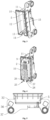
- the invention provides a wiring device 1, which facilitates the wiring of an electronic control box, and is easy to assemble and disassemble.
- the wiring device 1 includes a first terminal assembly 2 and a second terminal assembly 3, wherein the first terminal assembly 2 is used to be connected to the electronic control box, the second terminal assembly 3 is used to be connected to the first base (not shown), and the first terminal assembly 2 is connected to the second terminal assembly 3, so as to achieve the connection of the wires, thereby connecting the electronic control box with the electronic components in the first base for the conduction of the circuit.
- the first base is a lower base of the air conditioner. It should be understood that according to another embodiment not forming part of the invention, the first base is an upper base of the air conditioner, or the first base is other bases included in housings of other electronic components.
- the first terminal assembly 2 includes a first wiring terminal 4 and a first sliding structure 6, and the first wiring terminal 4 is used to be connected to the electronic control box to guide the wires drawn out of the electronic control box through the first wiring terminal 4, so that the wiring drawn out of the electronic control box avoids experiencing wiring confusion and crimping. Further, the first sliding structure 6 is connected to a side surface of the first wiring terminal 4.
- the second terminal assembly 3 includes a second wiring terminal 5 and a first guiding structure 7, wherein the first guiding structure 7 is connected to a side surface of the second wiring terminal 5.
- the first sliding structure 6 is connected to the first guiding structure 7, and the first sliding structure 6 moves relative to the first guiding structure 7 in a first direction, i.e., the first wiring terminal is slidably connected to the second wiring terminal 5 through the first sliding structure 6 relative to the first guiding structure 7 in the first direction, i.e., the guiding for the first sliding structure 6 through the first guiding structure 7 facilitates the connection of first wiring terminal 4 to the second wiring terminal 5.
- both the first wiring terminal 4 to the second wiring terminal 5 are opened with a wiring hole 8 extending in the first direction, and the guiding for the first sliding structure 6 in the first direction through the first guiding structure 7 avoids a shear force caused by the wiring for the wiring hole 8 from the first wiring terminal 4 or the second wiring terminal 5 when the first wiring terminal 4 moves in the first direction and is connected to the second wiring terminal 5, i.e., the mounting efficiency between the first wiring terminal 4 and the second wiring terminal 5 is improved and the connection between the first wiring terminal 4 and the second wiring terminal 5 is facilitated without affecting the wire leading.
- the first base has a plane (not shown) for disposing the mounting structure 31, wherein the first direction is perpendicular to the plane.
- the first sliding structure 6 includes a first guiding block 9 extending in the first direction, and the first guiding block 9 is connected to the side surface of the first wiring terminal 4.
- the first guiding block 9 extending in the first direction cooperates with the first guiding structure 7, and slide relative to the first guiding structure 7 in the first direction, so that the first wiring terminal 4 moves relative to the second wiring terminal 5 in the first direction to be connected to the second wiring terminal 5.
- the first wiring terminal 4 has a substantially rectangular prism shape.
- the first guiding block 9 has nine blocks, the plurality of the first guiding blocks 9 are connected to two opposite side surfaces of the first wiring terminal 4 respectively, and the first guiding block 9 extends from one end of the first wiring terminal 4 away from the first base toward the other end of the first wiring terminal 4 in the first direction.
- a thickness of the end of the first guiding block 9 away from the first base gradually decreases along the extending direction thereof, i.e., the first guiding block first contacts one end of the first guiding structure 7 when the first guiding block 9 cooperates with the first guiding structure 7, so that one end surface of the first guiding block 9 forms an inclined surface or a curved surface, so as to facilitate the cooperation between the first guiding block 9 and the first guiding structure 7.
- the first guiding block 9 has two blocks, the two first guiding blocks 9 are disposed on two opposite side surfaces of the first wiring terminal 4 respectively, and the two first guiding blocks 9 are disposed at a centerline of their respective side surface.
- the first guiding structure 7 includes a receiving body 10 and a first chute 13 opened on the receiving body 10, and the receiving body 10 is connected to the second wiring terminal 5 and corresponds to the first wiring terminal 4; the first wiring terminal 4 moves relative to the receiving body 10 in the first direction to abut against the second wiring terminal 5, and the first guiding block 9 extends into the first chute 13 and slide relative to the first chute 13 in the first direction.
- the guiding for the first wiring terminal 4 through the receiving body 10 and the guiding for the first guiding block 9 through the first chute 13 facilitates the connection and guiding between the first wiring terminal 4 and the second wiring terminal 5, thereby greatly simplifying the difficulty in connection between the first wiring terminal 4 and the second wiring terminal 5.
- the receiving body 10 is provided inside with a guiding space 12 extending in the first direction, and the second wiring terminal 5 is disposed in the receiving body 10 and located on one end of the guiding space 12.
- the first wiring terminal 4 extends into the guiding space 12 and slide along the guiding space 12 to abut against the second wiring terminal 5, i.e., guiding the first wiring terminal 4 through the guiding space 12.
- a width and a length of an end of the guiding space 12 away from the second wiring terminal 5 gradually increases in a direction away from the second wiring terminal 5, i.e., the width and the length of the end of the receiving body 10 away from the second wiring terminal 5 is larger than a width and a length of an end of the receiving body 10 close to the second wiring terminal 5, so as to facilitate the alignment of the first wiring terminal 4, so that the first wiring terminal 4 easily extends into the guiding space 12.
- the receiving body 10 is provided outside with a plurality of reinforcing ribs 15, and the plurality of reinforcing ribs 15 are disposed at intervals on one side of an end of the receiving body 10 away from the second wiring terminal 5, which is opposite to the guiding space 12, i.e., the reinforcing ribs 15 are disposed at a larger end of the receiving body 10 and the reinforcing ribs 15 are connected outside the receiving body 10, so that an impact force of the first wiring terminal 4 on the receiving body 10 when extending into the guiding space 12 is received by the reinforcing ribs 15 for ensuring the strength of the receiving body 10 and prolonging the service life of the receiving body 10.
- the receiving body 10 is adapted to the first wiring terminal 4, i.e., a shape enclosed by an outline of a cross section of the receiving body 10 is substantially rectangular, so that the first wiring terminal 4 is stably received inside the guiding space 12.
- the plurality of reinforcing ribs 15 are disposed on two opposite side surfaces of the receiving body 10, and the first chute 13 is opened on the other two side surfaces.
- a side surface of the receiving body 10 is provided with a plurality of accommodating portions 11, a plurality of the first chutes 13 are respectively formed inside the plurality of accommodating portions 11, and the plurality of the first chutes 13 are communicated to the inside of the receiving body 10. That is, in the invention, the plurality of accommodating portions 11 are disposed on two opposite side surfaces of the receiving body 10 respectively, and the accommodating portions 11 are disposed outside the receiving body 10.
- the first chute 13 is opened inside the accommodating portion 11, and the first chute 13 penetrates through a circumferential wall of the receiving body 10 to be communicated to the guiding space 12, so that when the first wiring terminal 4 extends into the guiding space 12, the first guiding block 9 connected to the first wiring terminal 4 extends into the first chute 13 and slide along the first chute 13.
- an end of the receiving body 10 away from the second wiring terminal 5 is provided with a guiding port 14 corresponding to the plurality of accommodating portions 11, and the guiding port 14 penetrates through the circumferential wall of the receiving body 10 and is communicated to the second chute 24, so that when the first wiring terminal 4 extends into the guiding space 12, the first guiding block 9 is guided through the guiding port 14 such that the first guiding block 9 extends into the first chute 13.
- the accommodating portion 11 corresponds to the first guiding block 9, i.e., the accommodating portion 11 has two portions, and the two accommodating portions 11 are disposed on two opposite side surfaces of the receiving body 10 respectively, i.e., the accommodating portions 11 are disposed on two side surfaces on the receiving body 10 in which the reinforcing ribs 15 are disposed adjacent to the receiving body 10. And, the accommodating portions 11 are disposed at a centerline of respectively side surfaces to facilitate the extension of the first guiding block 9 into the first chute 13 when the first wiring terminal 4 cooperates with the guiding space 12, so as to facilitate the guiding for the first wiring terminal 4 by the guiding space 12 and the guiding for the first guiding block 9 by the first chute 13.
- the first wiring terminal 4 When the first wiring terminal 4 is required to be connected to the second wiring terminal 5, the first wiring terminal 4 is extended into the guiding space 12 and the first guiding block 9 is aligned to the guiding port 14, so that the first wiring terminal 4 extends into the first chute 13 through the guiding port 14 and moves the first wiring terminal 4 in the first direction, i.e., extending the first wiring terminal 4 into the guiding space 12 and extending the first guiding block 9 into the first chute 13. Moving the first wiring terminal 4 to abut against the second wiring terminal 5 completes the connection between the first wiring terminal 4 and the second wiring terminal 5.
- the first sliding structure 6 is integrally formed with the first wiring terminal 4, and the first guiding structure 7 is integrally formed with the second wiring terminal 5. It is to be understood that according to another embodiment not forming part of the invention, the first sliding structure 6 is connected to the first wiring terminal 4 by other methods, such as by welding or bonding. Similarly, according to another embodiment not forming part of the invention, the first sliding structure 6 is connected to the second wiring terminal 5 by other methods, such as by welding or bonding.
- the wiring device 1 further includes a carrying body 18, and the carrying body 18 is used to be connected to the electronic control box.
- the first terminal assembly 2 further includes a second sliding structure 17, the second sliding structure 17 is connected to a side surface of the first wiring terminal 4, and the second sliding structure 17 extends in a second direction.
- the second sliding structure 17 cooperates with the carrying body 18, so that the first wiring terminal 4 is connected to the electronic control box through the cooperation of the second sliding structure 17 and the carrying body 18.
- the second sliding structure 17 includes a plurality of second guiding blocks 19 extending in the second direction, and the plurality of second guiding blocks 19 are connected to the side surface of the first wiring terminal 4.
- the carrying body 18 is opened with a plurality of second chutes 24 corresponding to the plurality of second guiding blocks 19, and the second guiding blocks 19 extends into the second chute 24 and move relative to the second chute 24 in the second direction. That is, the first wiring terminal 4 is connected to the electronic control box through the guiding of the plurality of second guiding blocks 19 by the second chute 24.
- the second direction is perpendicular to the first direction.
- the first terminal assembly 2 further includes a locking buckle 25, the locking buckle 25 is disposed on the side surface of the first wiring terminal 4, and the locking buckle 25 is located on one side of the second sliding structure 17 in the second direction.
- the carrying body 18 is further provided with a buckling portion 29 matching with the locking buckle 25, the buckling portion 29 is located on one end of the second chute 24, and the locking buckle 25 moves in the first direction to be engaged to the buckling portion 29. That is, when the first wiring terminal 4 moves along the second chute 24 through the second guiding block 19, the locking buckle 25 is driven to move in the second direction, and when the locking buckle 25 is engaged to the buckling portion 29, the first wiring terminal 4 is stably connected to the electronic control box.
- the second sliding structure 17, the carrying body 18, the locking buckle 25 and the buckling portion 29 together form a guide mounting structure 16, i.e., the guide mounting structure 16 includes the carrying body 18, the second sliding structure 17, the locking buckle 25 and the buckling portion 29. That is, the first wiring terminal 4 is connected to the electronic control box through the guide mounting structure 16, so as to simplify the difficulty in connection between the first wiring terminal 4 and the electronic control box.
- the buckling portion 29 is connected to one side of the carrying body 18, both the second sliding structure 17 and the locking buckle 25 are connected to the first wiring terminal 4, and the locking buckle 25 is located on one side of the second sliding structure 17; the second sliding structure 17 is slidably connected to the carrying body 18, and the second sliding structure 17 slides relative to the carrying body 18 until the locking buckle 25 is buckled to the buckling portion 29.
- the stable connection between the first wiring terminal 4 and the electronic control box is realized by the cooperation between the locking buckle 25 and the buckling portion 29.
- the plurality of second guiding blocks 19 are connected to two opposite side surfaces of a side surface of the first wiring terminal 4 in which the first guiding block 9 is disposed adjacent to the first wiring terminal 4, and the plurality of second guiding blocks 19 are disposed adjacent to a side of a side surface in which the first guiding block 9 is disposed perpendicular to the first wiring terminal 4.
- the second guiding blocks 19 disposed on the same side of the first wiring terminal 4 have two blocks, the two second guiding blocks 19 are disposed on two ends of the above sides respectively, and the two second guiding blocks 19 are arranged in the second direction.
- the carrying body 18 includes a carrying main body 20 and two guiding bodies 21.
- the carrying main body 20 has a first side and a second side that are disposed oppositely, the first side of the carrying main body 20 is used to be connected to the electronic control box, wherein the connection manner is integrated molding, welding or fastening, etc., and in the invention, the integrated molding method is adopted.
- the two guiding bodies 21 are disposed oppositely on the second side of the carrying main body 20, wherein there is a gap between the two guiding bodies 21, and the second sliding structure 17 slides in a gap between the two guiding bodies 21.
- the second chute 24 are opened on the side surfaces of the two guiding bodies 21 that are close to each other, the plurality of second guiding blocks 19 on two sides of the first wiring terminal 4 that are disposed oppositely extends into the second chute 24 of the two guiding bodies 21 respectively and slide relative to the second chute 24.
- a distance between the two guiding bodies 21 is adapted to a distance between the two sides of the first wiring terminal 4 where the second guiding body 21 is disposed, i.e., the distance between the two guiding bodies 21 is adapted to a thickness of the first wiring terminal 4, so that the first wiring terminal 4 stably slides between the two guiding bodies 21.
- the guiding body 21 includes a guiding portion 22 and a plurality of limit portions 23, wherein a side of the guiding portion 22 is connected to the carrying main body 20, and the guiding portion 22 extends in the second direction.
- the plurality of limit portions 23 are disposed on the other side of the guiding portion 22, and the plurality of limit portions 23 are arranged in the second direction, wherein the carrying main body 20, the guiding portion 22 and the plurality of limit portions 23 form the second chute 24 together.
- the plurality of limit portions 23 correspond to the plurality of second guiding blocks 19, and the plurality of second guiding blocks 19 slides relative to the second chute 24 to be located between the corresponding limit portions 23 and the carrying main body 20. That is, in the invention, both the limit portions 23 and the second guiding blocks 19 have two, and the two limit portions 23 are disposed at two end so the guiding portion 22 respectively, so that when the two second guiding blocks 19 slide to the end of the guiding body 21 along the second chute 24, the two second guiding blocks 19 is located between the two limit portions 23 and the carrying main body 20 respectively, so that the second guiding blocks 19 is prevented from being disengaged with the second chute 24 through the limit portions 23.
- the buckling portions 29 are connected to the carrying main body 20, and the buckling portions 29 are located on one end of the guiding portion 22 in the second direction.
- the locking buckle 25 is connected to the first wiring terminal 4, and the locking buckle 25 is located on one side of the second guiding blocks 19 in the second direction.
- the first wiring terminal 4 slides relative to the two guiding bodies 21 to the end of the guiding bodies 21, so as to facilitate the buckling of the locking buckle 25 on the first wiring terminal 4 to the buckling portions 29 disposed on the guiding portion 22.
- One end of the buckling portions 29 away from the guiding portion 22 is provided with a first stop surface 30, and the first stop surface 30 faces towards the second direction;
- the locking buckle 25 is provided with a second stop surface 26 facing towards the second guiding blocks 19, and the first stop surface 30 abuts against the second stop surface 26 such that the buckling portions 29 are buckled to the locking buckle 25.
- the buckling portions 29 have two portions, the two buckling portions 29 are connected to the end of the two guiding portions 22 respectively, and the two buckling portions 29 extend in a direction away from the guiding portions 22. Further, a distance between the two buckling portions 29 gradually decreases in the second direction. As a result, side surfaces of the two buckling portions 29 that are close to each other form two slopes, so that the locking buckles 25 are buckled to the buckling portions 29.
- the number of the locking buckles 25 corresponds to the number of the buckling portions 29, i.e., there are two locking buckles 25, and the two locking buckles 25 are respectively disposed on two sides of the first guiding blocks 9.
- the locking buckle 25 includes connecting portions 27 and wedge-shaped portions 28; one end of the connecting portions 27 is connected to the first wiring terminal 4, the wedge-shaped portions 28 are connected to one end of the connecting portions 27 away from the first wiring terminal 4, and one side of the wedge-shaped portions 28 away from the connecting portions 27 is a slope; the second stop surface 26 is disposed on one side of the wedge-shaped portions 28 close to the connecting portions 27. That is, the two wedge-shape portions 28 are protruded from side surfaces of the two connecting portions 27 that are away from each other.
- the slope on the wedge-shaped portion 28 is affixed to the slope of the buckling portion 29; when the locking buckle 25 continues to move in the second direction, the connecting portion 27 experiences an elastic deformation, and the two connecting portions 27 move close to each other, so that the wedge-shaped portion 28 bypasses the buckling portion 29.
- the wedge-shaped portion 28 bypasses the buckling portion 29
- the wedge portion 28 is rebounded and the first stop surface 30 is abutted against the second stop surface 26 due to the elastic restoring force of the connecting portion 27, thereby completing the buckling between the locking buckle 25 and the buckling portion 29.
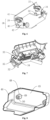
- the wiring device 1 further includes a mounting structure 31, wherein the mounting structure 31 is connected to the second wiring terminal 5, and the second wiring terminal 5 is connected to the first base through the mounting structure 31.
- the mounting structure 31 includes a mounting body 32, a fixing buckle 33, an elastic member 35 and a positioning member 34, wherein the mounting body 32 is connected to the second wiring terminal 5.
- One ends of the fixing buckle 33 and the positioning member 34 are used to be connected to the first base.
- the fixing buckle 33 passes through the mounting body 32 and be buckled to the mounting body 32, and the elastic member 35 is disposed close to the fixing buckle 33 and the elastic member 35 is used to be abutted between the first base and the mounting body 32, so that the fixing buckle 33 is stably buckled to the mounting body 32 by an elastic force of the elastic member 35.
- the positioning member 34 passes through the mounting body 32, wherein the positioning member 34 is used for positioning when the second wiring terminal 5 is connected to the first base, so that through the positioning of the positioning member 34, the positioning accuracy of the second wiring terminal 5 is improved to ensure that the second wiring terminal 5 is connected at a suitable position.
- connection error between the second wiring terminal 5 and the first wiring terminal 4 is eliminated by the elastic member 35, and the tolerance is automatically adjusted by the elastic member 35, so that the tolerance caused by the user's inaccurate mounting is reduced, and a situation where the second wiring terminal 5 and the first wiring terminal 4 are not plugged in and the pin is bent is avoided.
- the mounting body 32 is opened with a mounting hole 36 and a positioning hole 37, and the fixing buckle 33 passes through the mounting hole 36 to be buckled to a side surface of the mounting body 32.
- the positioning member 34 passes through the positioning hole 37 for positioning the mounting body 32 through the cooperation of the positioning member 34 and the positioning hole 37.
- the mounting body 32 has two bodies, the two mounting bodies 32 are disposed at two opposite sides of the second wiring terminal 5 respectively, and each of the mounting bodies 32 is at least opened with one mounting hole 36 and at least one positioning hole 37, i.e., being connected to the corresponding fixing buckle 33 and the corresponding positioning hole 37 through the mounting bodies 32 disposed on two opposite sides of the second wiring terminal 5, so that the stability of connection between the second wiring terminal 5 and the first base is improved.
- each of the mounting bodies 32 is opened with one mounting hole 36 and one positioning hole 37.
- the fixing buckle 33 includes a plurality of hooks 38, one end of the plurality of hooks 38 is provided with a third stop surface 41 facing towards the other side of the hooks 38, and the hooks 38 passes through the mounting bodies 32 such that the third stop surface 41 is abutted against a side surface of the mounting bodies 32, i.e., buckling the hooks 38 to the mounting bodies 32.
- One end of the hooks 38 away from the third stop surface 41 is used to be connected to the first base.
- the plurality of hooks 38 pass through the mounting hole 36, and the portion of the hooks 38 passing through the mounting hole 36 abuts against the side surface of the mounting bodies 32 such that the hooks 38 are buckled to the mounting bodies 32.
- the hook 38 includes an elastic connecting portion 39 and an abut portion 40, and one end of the elastic connecting portion 39 is used to be connected to the first base; the abut portion 40 is connected to the other end of the elastic connecting portion 39, and the third stop surface 41 is disposed at one side of the abut portion 40 close to the elastic connecting portion 39; one side of the abut portion 40 away from the elastic connecting portion 39 is a slope. That is, in the invention, through the abutment of a side of the abut portion 40 close to the elastic connecting portion 39 against the mounting bodies 32, the buckling of the hooks 38 to the mounting bodies 32 is achieved.
- the plurality of elastic connecting portions 39 are disposed at intervals, and enclosed to form a circle.
- the plurality of the abut portions 40 are protruded from a side away from each other of the plurality of the elastic connecting portions 39 such that the plurality of the third stop surfaces 41 are respectively located on one side away from each other of the plurality of the elastic connecting portions 39.
- a circle formed by the side surfaces of the plurality of elastic connecting portions 39 away from each other is adapted to a hole diameter of the mounting hole 36, so that when the elastic connecting portions 39 pass through the mounting hole 36, the elastic connecting portions is attached to an inner peripheral wall of the mounting hole 36, and is engaged with the mounting bodies 32 through the abut portion 40 protruding from the elastic connecting portions 39.
- a side of the abut portion 40 away from the elastic connecting portion 39 is a slope, and a plurality of slopes on the plurality of abut portions 40 face towards the sides of the plurality of elastic connecting portions 39 away from each other, so that when the plurality of hooks 38 are required to extend into the mounting hole 36, a hole wall of the mounting hole 36 is abutted by the slope disposed on the abut portion 40 to continue to extend the hooks 38 into the mounting hole 36; through the abutment of the abut portion 40 by the hole wall of the mounting hole 36, the plurality of elastic connecting portions 39 experience an elastic deformation and move close to each other, so that the abut portion 40 passes through the mounting hole 36; after the plurality of abut portions 40 pass through the mounting hole 36, the abut portion 40 is restored to the original position due to the elastic restoring force of the elastic connecting portion 39, so that the third stop surface 41 abuts against the side surface of the mounting body 32, thereby achieving the buckling of the hooks 38
- the hooks 38 have two hooks, and the two hooks 38 are disposed oppositely, that is, when two of the elastic connecting portions 39 extend into the mounting hole 36, the two elastic connecting portions 39 are located at two sides in a center of the mounting hole 36 respectively, and the two abut portions 40 protrude from the side surfaces of the two elastic connecting portions 39 away from each other respectively.
- the elastic member 35 is wound around the plurality of elastic connecting portions 39, i.e., the elastic member 35 is sleeved outside the fixing buckle 33, so that when the mounting body 32 is mounted to the fixing buckle 33 for being abutted between the mounting body 32 and the first base through the elastic member 35 and providing a guide for the elastic member 35 through the fixing buckle 33, so that the elastic member 35 stably provides an elastic force for the mounting body 32, and hence the elastic member 35 stably and effectively provides the effect of correcting the mounting tolerance for the mounting body 32.
- the elastic member 35 is a spring.
- the positioning member 34 includes a plurality of positioning posts 42, ends of the plurality of the positioning posts 42 are used to be connected to the first base, and heights of the plurality of the positioning posts 42 are greater than a height of the fixing buckle 33.
- one end of the positioning post 42 away from the first base is opened with a round chamfer, i.e., the end of the positioning post 42 away from the first base has a diameter that gradually decreases away from the first base, so that the positioning post 42 extends into the positioning hole 37, which facilitates the positioning of the positioning post 42 for the mounting body 32.
- the mounting structure 31 further includes a plurality of ribs 52, the plurality of ribs 52 are disposed at intervals on the ends of the fixing buckle 33 and the positioning member 34, and the plurality of ribs 52 are used to be connected to the first base. That is, when the fixing buckle 33 and the positioning member 34 are connected to the first base, the plurality of ribs 52 are connected to the fixing buckle 33 and the first base, or the plurality of ribs 52 are connected to the positioning member 34 and the first base, so that the stability of connecting between the fixing buckle 33 and the first base and the stability of connecting between the positioning member 34 and the first base are enhanced by the ribs 52.
- the second wiring terminal 3 further includes a wiring head and a protective cover plate 43, and the wiring head is connected to one end of the second wiring terminal 5 away from the first wiring terminal 4 for drawing out connecting wires through the wiring head.
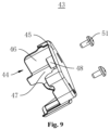
- the protective cover plate 43 has inside a receiving space 47; the protective cover plate 43 covers the second wiring terminal 5 such that the wiring head is received inside the receiving space 47, the protective cover plate 43 is opened with a positioning connecting member 51 matching with the positioning member 34, and the positioning member 34 is connected to the positioning connecting member 51 to be connected to the protective cover plate 43.
- the protective cover plate 43 includes a cover plate body 44 and the positioning connecting member 51.
- the cover plate body 44 is used to cover the second wiring terminal 5, and make the second wiring terminal 5 be received inside the cover plate body 44, i.e., making the wiring head be received inside the cover plate body 44.
- the positioning connecting portion 48 is connected to the cover plate body 44, and the positioning connecting portion 48 is used to be connected to the positioning member 34.
- the receiving space 47 is opened inside the cover plate body 44, and the receiving space 47 is used to receive the second wiring terminal 5 and the wiring head. And, the positioning connecting portion 48 is disposed inside the receiving space 47, which simplifies the structure of the protective cover plate 43.
- the cover plate body 44 includes a top plate 45 and a plurality of side plates 46, the plurality of side plates 46 are connected to a plurality of sides of the top plate 45 respectively, i.e., the plurality of side plates 46 and the top plate 45 enclose the receiving space 47 together, one end of the plurality of side plates 46 away from the top plate 45 is used to abut against the first base, and one of the side plates 46 of the top plate 45 forms an opening so that the second wiring terminal 5 extends into the receiving space 47 through the opening.
- a shape of the top plate 45 matches an overall shape formed by the second wiring terminal 5 and the mounting body 32, so that the cover plate body 44 receives the second wiring terminal 5 and the mounting body 32 in the receiving space 47 to ensure that the protective cover plate 43 effectively provides protection to the second wiring terminal 5 and the mounting body 32, thereby preventing water stains from falling on the second wiring terminal 5 or the mounting body 32.
- the plurality of side plates 46 are provided with a circular arc transition section at the j oint where it is connected to the top plate 45, so as to prevent the user from being harmed when the protective cover plate 43 is disassembled.
- the positioning connecting portion 48 is disposed on one side of the top plate 45 close to the receiving space 47, and the positioning connecting portion 48 is used to abut against the positioning member 34. That is, when the cover plate body 44 covers the second wiring terminal 5, the positioning connecting portion 48 abuts against the positioning member 34 extending from the mounting body 32 within the receiving space 47, so as to achieve the positioning of the cover plate body 44, and to facilitate the connection of the cover plate body 44.
- the protective cover plate 43 further includes a positioning connecting member 51, and the positioning connecting member 51 passes through the positioning connecting portion 48 and is used to be connected to the positioning member 34, so that the cover plate body 44 stably covers the second wiring terminal 5 through the previous cooperation between the positioning connecting member 51 and the positioning member 34.
- the positioning connecting portion 48 is provided inside with a mounting space 49, and an end surface of the positioning connecting portion 48 away from the top plate 45 is opened with a positioning connecting hole 50, and the mounting space 49 is communicated to the receiving space 47 through the positioning connecting hole 50, so that the positioning connecting member 51 passes through the positioning connecting hole 50 to facilitate the connection between the positioning connecting member 51 and the positioning member 34.
- a diameter of one end of the mounting space 49 away from the receiving space 47 gradually increases in a direction away from the receiving space 47, so as to facilitate the extension of the positioning connecting member 51 into the mounting space 49.
- the assembly efficiency of the positioning connecting member 51 is improved.
- a diameter of the positioning connecting hole 50 is smaller than a diameter of the mounting space 49, so that when the positioning connecting member 51 is connected to the positioning member 34, the positioning connecting portion 48 abuts against the positioning member 34 to ensure that the cover plate body 44 stably covers the second wiring terminal 5.
- the positioning connecting member 51 is a screw, and passing the screw through the positioning connecting hole 50 and screwing the screw into the positioning member 34 abuts the positioning connecting portion 48 against the position member 34 by a screw nut of the screw, and makes the cover plate body 44 stably cover the second wiring terminal 5.
- the first wiring terminal 4 moves in the first direction relative to the second wiring terminal 5 and is connected to the second wiring terminal 5, so as to ensure that the guiding connection between the first wiring terminal 4 and the second wiring terminal 5 is facilitated without affecting leads in the wiring hole 8 that extends in the first direction, thereby facilitating the assembly and disassembly between the first wiring terminal 4 and the second wiring terminal 5.
- the first wiring terminal 4 is guided by the guiding space 12 when the first wiring terminal 4 is connected to the second wiring terminal 5, and through the guiding for the first guiding block 9 by the first chute 13, the guiding connection between the first wiring terminal 4 and the second wiring terminal 5 is further facilitated, thereby making the assembly and disassembly more convenient and fast.
- the first wiring terminal 4 is connected to the carrying body 18 through the second sliding structure 17 by the sliding cooperation between the second sliding structure 17 and the carrying body 18, i.e., facilitating the guiding connection between the first wiring terminal 4 and the electronic control box, thereby facilitating the connection of the first wiring terminal 4 to the electronic control box.
- the mounting structure 31 on the second wiring terminal 5 the connection of the second wiring terminal 5 to the first base is facilitated by the engagement between the fixing buckle 33 and the mounting body 32, by the positioning between the positioning member 34 and the mounting body 32, and by the error adjustment of the second wiring terminal 5 with the elastic member 35.
- the protective cover plate 43 covering the second wiring terminal 5 for preventing the user from connecting the wires inside the second wiring terminal 5 the stability in connection of the wires is guaranteed and the danger of electronic shock to users is avoided, and water stains will be ensured not to splash into the second terminal 5 and not to cause a short circuit in the wiring when the wiring device 1 is cleaned.
- the invention provides an air conditioner, which employs the wiring device 1 provided in Embodiment One, which facilitates the wiring of an electronic control box, and is easy to assemble and disassemble.
Landscapes
- Details Of Connecting Devices For Male And Female Coupling (AREA)
- Connection Or Junction Boxes (AREA)
- Connections Arranged To Contact A Plurality Of Conductors (AREA)
- Air Filters, Heat-Exchange Apparatuses, And Housings Of Air-Conditioning Units (AREA)
Claims (9)
- Verdrahtungsvorrichtung, die verwendet wird zur Verbindung mit einem elektronischen Steuerkasten, wobei die Verdrahtungsvorrichtung (1) eine erste Anschlussanordnung (2) und eine zweite Anschlussanordnung (3) umfasst, wobei die erste Anschlussanordnung (2) einen ersten Kabelschuh (4) und eine erste Gleitstruktur (6) umfasst, wobei der erste Kabelschuh (4) verwendet wird zur Verbindung mit dem elektronischen Steuerkasten, und die erste Gleitstruktur (6) mit einer Seitenfläche des ersten Kabelschuhs (4) verbunden ist; die zweite Anschlussanordnung (3) einen zweiten Kabelschuh (5) und eine erste Führungsstruktur (7) umfasst, und die erste Führungsstruktur (7) mit einer Seitenfläche des zweiten Kabelschuhs (5) verbunden ist;sowohl der erste Kabelschuh (4) als auch der zweite Kabelschuh (5) mit einer Vielzahl von Verdrahtungslöchern (8) geöffnet sind, die sich in einer ersten Richtung erstrecken, die erste Gleitstruktur (6) mit der ersten Führungsstruktur (7) verbunden ist, und die erste Gleitstruktur (6) sich relativ zu der ersten Führungsstruktur (7) in der ersten Richtung bewegt;dadurch gekennzeichnet, dassdie zweite Anschlussanordnung (3) ferner eine Befestigungsstruktur (31) umfasst, und die Befestigungsstruktur (31) einen Befestigungskörper (32), eine Fixierungsraste (33), ein elastisches Element (35) und ein Positionierungselement (34) umfasst; der Befestigungskörper (32) mit einer Seitenfläche des zweiten Kabelschuhs (5) verbunden ist, und der Befestigungskörper (32) mit einem Befestigungsloch (36) und einem Positionierungsloch (37) geöffnet ist; sowohl die Fixierungsraste (33) als auch das Positionierungselement (34) dazu verwendet werden, mit einer ersten Basis verbunden zu werden, die in einem Gehäuse eines elektronischen Bauelements eingeschlossen ist,und das Positionierungselement (34) sich in das Positionierungsloch (37) erstreckt; die Fixierungsraste (33) sich in das Befestigungsloch (36) erstreckt und mit dem Befestigungskörper (32) verbunden ist, und das elastische Element (35) mit der Fixierungsraste (33) verbunden ist und verwendet wird, um zwischen dem Befestigungskörper (32) und der ersten Basis anzuliegen.
- Verdrahtungsvorrichtung nach Anspruch 1, wobei die erste Gleitstruktur (6) einen ersten Führungsblock (9) umfasst, der sich in der ersten Richtung erstreckt, und der erste Führungsblock (9) mit einer Seitenfläche des ersten Kabelschuhs (4) verbunden ist, die erste Führungsstruktur (7) einen Aufnahmekörper (10) und eine erste Rutsche (13) umfasst, die auf dem Aufnahmekörper (10) geöffnet ist, und der Aufnahmekörper (10) mit dem zweiten Kabelschuh (5) verbunden ist und dem ersten Kabelschuh (4) entspricht; der erste Kabelschuh (4) sich relativ zu dem Aufnahmekörper (10) in der ersten Richtung bewegt, um gegen den zweiten Kabelschuh (5) zu stoßen, und der erste Führungsblock (9) sich in die erste Rutsche (13) erstreckt und relativ zu der ersten Rutsche (13) in der ersten Richtung gleitet.
- Verdrahtungsvorrichtung nach Anspruch 2, wobei der Aufnahmekörper (10) innen mit einem Führungsraum (12) geöffnet ist, der sich in der ersten Richtung erstreckt, und der zweite Kabelschuh (5) an einem Ende des Führungsraums (12) angeordnet ist; eine Breite und eine Länge eines Endes des Führungsraums (12), das von dem zweiten Kabelschuh (5) entfernt ist, allmählich in einer Richtung weg von dem zweiten Kabelschuh (5) zunimmt.
- Verdrahtungsvorrichtung nach Anspruch 3, wobei der Aufnahmekörper (10) mit einer Vielzahl von Verstärkungsrippen (15) versehen ist, wobei die Vielzahl von Verstärkungsrippen (15) in Abständen auf einer Seite eines Endes des Aufnahmekörpers (10), das von dem zweiten Kabelschuh (5) entfernt ist, angeordnet sind, das dem Führungsraum (12) gegenüberliegt.
- Verdrahtungsvorrichtung nach Anspruch 2, wobei eine Seitenfläche des Aufnahmekörpers (10) mit einer Vielzahl von Aufnahmeabschnitten (11) versehen ist, eine Vielzahl der ersten Rutschen (13) jeweils innerhalb der Vielzahl von Aufnahmeabschnitten (11) ausgebildet ist und die Vielzahl der ersten Rutschen (13) mit dem Inneren des Aufnahmekörpers (10) in Verbindung steht.
- Verdrahtungsvorrichtung nach Anspruch 1, wobei die erste Anschlussanordnung (2) ferner eine zweite Gleitstruktur (17) umfasst, und die zweite Gleitstruktur (17) eine Vielzahl von zweiten Führungsblöcken (19) umfasst, die sich in einer zweiten Richtung erstrecken; die Vielzahl von zweiten Führungsblöcken (19) mit einer Seitenfläche des ersten Kabelschuhs (4) verbunden ist; die Verdrahtungsvorrichtung (1) ferner einen Tragkörper (18) umfasst, und der Tragkörper (18) verwendet wird, um mit dem elektronischen Steuerkasten verbunden zu werden; der Tragkörper (18) mit einer Vielzahl von zweiten Rutschen (24) geöffnet ist, die der Vielzahl von zweiten Führungsblöcken (19) entspricht, und der zweite Führungsblock (19) sich in die zweite Rutsche (24) erstreckt und relativ zu der zweiten Rutsche (24) in der zweiten Richtung gleitet.
- Verdrahtungsvorrichtung nach Anspruch 6, wobei die erste Anschlussanordnung (2) ferner eine Sperrraste (25) umfasst und die Sperrraste (25) an einer Seitenfläche des ersten Kabelschuhs (4) angeordnet ist; der Tragkörper (18) ferner mit einem Knickabschnitt (29) versehen ist, der mit der Sperrraste (25) zusammenpasst, der Rastabschnitt (29) an einem Ende der zweiten Rutsche (24) angeordnet ist und die Sperrraste (25) sich in der zweiten Richtung bewegt, um mit dem Knickabschnitt (29) in Eingriff zu kommen.
- Verdrahtungsvorrichtung nach Anspruch 1, wobei die zweite Anschlussanordnung (3) ferner einen Verdrahtungskopf und eine Schutzabdeckplatte (43) umfasst; der Verdrahtungskopf mit einem Ende des zweiten Kabelschuhs (5), das entfernt von dem ersten Kabelschuh (4) ist, verbunden ist, und ein Aufnahmeraum (47) innerhalb der Schutzabdeckplatte angeordnet ist; die Schutzabdeckplatte (43) den zweiten Kabelschuh (5) abdeckt, so dass der Verdrahtungskopf in dem Aufnahmeraum (47) aufgenommen wird, die Schutzabdeckplatte (43) mit einem Positionierungsverbindungselement geöffnet wird, das zu dem Positionierungselement (34) passt, und das Positionierungselement (34) mit dem Positionierungsverbindungselement verbunden wird, um mit der Schutzabdeckplatte (43) verbunden zu werden.
- Klimaanlage, dadurch gekennzeichnet, dass die Klimaanlage die Verdrahtungsvorrichtung (1) nach einem beliebigen der Ansprüche 1 bis 8 umfasst.
Applications Claiming Priority (2)
| Application Number | Priority Date | Filing Date | Title |
|---|---|---|---|
| CN201820158951.5U CN207743489U (zh) | 2018-01-30 | 2018-01-30 | 接线装置及空调 |
| PCT/CN2018/125501 WO2019149013A1 (zh) | 2018-01-30 | 2018-12-29 | 接线装置及空调 |
Publications (4)
| Publication Number | Publication Date |
|---|---|
| EP3748787A1 EP3748787A1 (de) | 2020-12-09 |
| EP3748787A4 EP3748787A4 (de) | 2021-11-03 |
| EP3748787B1 true EP3748787B1 (de) | 2023-10-25 |
| EP3748787C0 EP3748787C0 (de) | 2023-10-25 |
Family
ID=63124047
Family Applications (1)
| Application Number | Title | Priority Date | Filing Date |
|---|---|---|---|
| EP18904337.5A Active EP3748787B1 (de) | 2018-01-30 | 2018-12-29 | Verdrahtungsvorrichtung und klimaanlage |
Country Status (7)
| Country | Link |
|---|---|
| EP (1) | EP3748787B1 (de) |
| JP (1) | JP6952194B2 (de) |
| CN (1) | CN207743489U (de) |
| AU (1) | AU2018406677B2 (de) |
| MY (1) | MY205528A (de) |
| NZ (1) | NZ765681A (de) |
| WO (1) | WO2019149013A1 (de) |
Families Citing this family (3)
| Publication number | Priority date | Publication date | Assignee | Title |
|---|---|---|---|---|
| CN207743489U (zh) * | 2018-01-30 | 2018-08-17 | 奥克斯空调股份有限公司 | 接线装置及空调 |
| CN108306155B (zh) * | 2018-01-30 | 2024-02-09 | 奥克斯空调股份有限公司 | 接线装置及空调 |
| CN207743432U (zh) * | 2018-01-30 | 2018-08-17 | 奥克斯空调股份有限公司 | 安装结构及空调 |
Family Cites Families (20)
| Publication number | Priority date | Publication date | Assignee | Title |
|---|---|---|---|---|
| US5071374A (en) * | 1990-09-24 | 1991-12-10 | Molex Incorporated | Floatable electrical connector with terminal position assurance component |
| FR2685134B1 (fr) * | 1991-12-17 | 1995-06-16 | Souriau & Cie | Connecteur de section polygonale comportant deux elements de connecteur positionnables automatiquement l'un par rapport a l'autre en cours d'accouplement. |
| JP2000091029A (ja) * | 1998-09-10 | 2000-03-31 | Furukawa Electric Co Ltd:The | コネクタ |
| JP2002346065A (ja) * | 2001-05-28 | 2002-12-03 | Heiwa Corp | 遊技部品接続装置 |
| JP2003187913A (ja) * | 2001-12-21 | 2003-07-04 | Furukawa Electric Co Ltd:The | 調芯機構 |
| DE10206423C1 (de) * | 2002-02-15 | 2003-08-14 | Tyco Electronics Amp Gmbh | Verriegelungsvorrichtung für einen elektrischen Steckverbinder |
| DE102005012153A1 (de) * | 2005-03-16 | 2006-05-11 | Siemens Ag | Steckverbindung |
| JP2006294305A (ja) * | 2005-04-06 | 2006-10-26 | Sumitomo Wiring Syst Ltd | コネクタの組付け構造 |
| JP4517940B2 (ja) * | 2005-05-27 | 2010-08-04 | 住友電装株式会社 | コネクタ |
| JP2007157684A (ja) * | 2005-11-11 | 2007-06-21 | Yazaki Corp | コネクタ |
| JP5316306B2 (ja) * | 2009-08-17 | 2013-10-16 | 住友電装株式会社 | コネクタ |
| JP2011249221A (ja) * | 2010-05-28 | 2011-12-08 | Sumitomo Wiring Syst Ltd | コネクタの取付構造 |
| CN203013958U (zh) * | 2012-11-06 | 2013-06-19 | 深圳胜蓝电气有限公司 | 端子座 |
| US8911258B2 (en) * | 2012-11-13 | 2014-12-16 | Airborn, Inc. | Right angle transition adapter with interchangeable gender components and method of use |
| CN203481529U (zh) * | 2013-10-12 | 2014-03-12 | 山东省科学院自动化研究所 | 一种柔性联接器用的自动导入装置 |
| JP6438382B2 (ja) * | 2015-12-15 | 2018-12-12 | ヒロセ電機株式会社 | 回路基板用電気コネクタ |
| CN106486836B (zh) * | 2016-11-18 | 2018-10-30 | 安徽江淮汽车集团股份有限公司 | 一种公端子护套与母端子护套配合结构 |
| CN106340749B (zh) * | 2016-11-18 | 2018-07-20 | 安徽江淮汽车集团股份有限公司 | 一种公端子护套与母端子护套配合结构 |
| CN207743489U (zh) * | 2018-01-30 | 2018-08-17 | 奥克斯空调股份有限公司 | 接线装置及空调 |
| CN108306155B (zh) * | 2018-01-30 | 2024-02-09 | 奥克斯空调股份有限公司 | 接线装置及空调 |
-
2018
- 2018-01-30 CN CN201820158951.5U patent/CN207743489U/zh active Active
- 2018-12-29 WO PCT/CN2018/125501 patent/WO2019149013A1/zh not_active Ceased
- 2018-12-29 AU AU2018406677A patent/AU2018406677B2/en active Active
- 2018-12-29 EP EP18904337.5A patent/EP3748787B1/de active Active
- 2018-12-29 JP JP2020524408A patent/JP6952194B2/ja active Active
- 2018-12-29 NZ NZ765681A patent/NZ765681A/en unknown
- 2018-12-29 MY MYPI2020003322A patent/MY205528A/en unknown
Also Published As
| Publication number | Publication date |
|---|---|
| EP3748787A4 (de) | 2021-11-03 |
| NZ765681A (en) | 2022-11-25 |
| JP2021503154A (ja) | 2021-02-04 |
| EP3748787A1 (de) | 2020-12-09 |
| MY205528A (en) | 2024-10-24 |
| CN207743489U (zh) | 2018-08-17 |
| WO2019149013A1 (zh) | 2019-08-08 |
| AU2018406677A1 (en) | 2020-04-02 |
| EP3748787C0 (de) | 2023-10-25 |
| AU2018406677B2 (en) | 2021-07-08 |
| JP6952194B2 (ja) | 2021-10-20 |
Similar Documents
| Publication | Publication Date | Title |
|---|---|---|
| EP3748787B1 (de) | Verdrahtungsvorrichtung und klimaanlage | |
| US8043127B2 (en) | Interlocking modular headers and header assemblies thereof | |
| EP0658956B1 (de) | Steckverbindersystem mit geringer Einsteckkraft | |
| KR100248972B1 (ko) | 단자 모듈을 구비한 전기 커넥터 | |
| US4755149A (en) | Blind mating connector | |
| US6341966B1 (en) | Electrical connector connecting system and intermediate board support for the same | |
| EP0345934A2 (de) | Schwebender Plattenaufbau für einen elektrischen Steckverbinder | |
| US5931688A (en) | Self docketing electrical connector assembly | |
| US11929578B2 (en) | Electrical connection device with insertion protection structure | |
| EP2149936B1 (de) | Verbinder | |
| US20150147900A1 (en) | Plug Connector And Electrical Connector Assembly | |
| US20190165515A1 (en) | Electrical connector | |
| WO2018037904A1 (ja) | ツイストペア線用ジョイントコネクタ | |
| EP3748781B1 (de) | Montagestruktur und klimaanlage | |
| MX2007010324A (es) | Montaje colector ensamblado sobre superficie que tiene una superficie de alineacion plana. | |
| US10181679B1 (en) | Electrical connector with terminal position assurance | |
| US10218124B1 (en) | Electrical connector with terminal position assurance | |
| CN115377756B (zh) | 电连接器及电连接器组合 | |
| JP2001203026A (ja) | ハウジングおよび、多段式コネクタの組付け方法 | |
| KR20190076885A (ko) | 억제 리브를 갖는 리셉터클 커넥터 하우징 | |
| US6382842B1 (en) | Plug-in optical connector with wrong plugging prevention key | |
| CN115441262A (zh) | 第一电连接器、第二电连接器及电连接器组合 | |
| CN217306798U (zh) | 电连接器 | |
| JP2005044586A (ja) | 電気接続用プラグ | |
| EP1047158A2 (de) | Elektrischer Verbinder |
Legal Events
| Date | Code | Title | Description |
|---|---|---|---|
| STAA | Information on the status of an ep patent application or granted ep patent |
Free format text: STATUS: THE INTERNATIONAL PUBLICATION HAS BEEN MADE |
|
| PUAI | Public reference made under article 153(3) epc to a published international application that has entered the european phase |
Free format text: ORIGINAL CODE: 0009012 |
|
| STAA | Information on the status of an ep patent application or granted ep patent |
Free format text: STATUS: REQUEST FOR EXAMINATION WAS MADE |
|
| 17P | Request for examination filed |
Effective date: 20200325 |
|
| AK | Designated contracting states |
Kind code of ref document: A1 Designated state(s): AL AT BE BG CH CY CZ DE DK EE ES FI FR GB GR HR HU IE IS IT LI LT LU LV MC MK MT NL NO PL PT RO RS SE SI SK SM TR |
|
| AX | Request for extension of the european patent |
Extension state: BA ME |
|
| DAV | Request for validation of the european patent (deleted) | ||
| DAX | Request for extension of the european patent (deleted) | ||
| A4 | Supplementary search report drawn up and despatched |
Effective date: 20211006 |
|
| RIC1 | Information provided on ipc code assigned before grant |
Ipc: H01R 13/506 20060101ALI20210930BHEP Ipc: H01R 13/447 20060101ALI20210930BHEP Ipc: H01R 13/62 20060101ALI20210930BHEP Ipc: H01R 24/60 20110101ALI20210930BHEP Ipc: H01R 13/52 20060101ALI20210930BHEP Ipc: H01R 13/631 20060101ALI20210930BHEP Ipc: H01R 13/73 20060101AFI20210930BHEP |
|
| REG | Reference to a national code |
Ipc: H01R0013629000 Ref country code: DE Ref legal event code: R079 Ref document number: 602018060189 Country of ref document: DE Free format text: PREVIOUS MAIN CLASS: H01R0013730000 |
|
| GRAP | Despatch of communication of intention to grant a patent |
Free format text: ORIGINAL CODE: EPIDOSNIGR1 |
|
| STAA | Information on the status of an ep patent application or granted ep patent |
Free format text: STATUS: GRANT OF PATENT IS INTENDED |
|
| RIC1 | Information provided on ipc code assigned before grant |
Ipc: H01R 13/73 20060101ALI20230621BHEP Ipc: H01R 13/631 20060101ALI20230621BHEP Ipc: H01R 13/629 20060101AFI20230621BHEP |
|
| INTG | Intention to grant announced |
Effective date: 20230705 |
|
| GRAS | Grant fee paid |
Free format text: ORIGINAL CODE: EPIDOSNIGR3 |
|
| GRAA | (expected) grant |
Free format text: ORIGINAL CODE: 0009210 |
|
| STAA | Information on the status of an ep patent application or granted ep patent |
Free format text: STATUS: THE PATENT HAS BEEN GRANTED |
|
| AK | Designated contracting states |
Kind code of ref document: B1 Designated state(s): AL AT BE BG CH CY CZ DE DK EE ES FI FR GB GR HR HU IE IS IT LI LT LU LV MC MK MT NL NO PL PT RO RS SE SI SK SM TR |
|
| REG | Reference to a national code |
Ref country code: GB Ref legal event code: FG4D |
|
| REG | Reference to a national code |
Ref country code: CH Ref legal event code: EP |
|
| REG | Reference to a national code |
Ref country code: DE Ref legal event code: R096 Ref document number: 602018060189 Country of ref document: DE |
|
| REG | Reference to a national code |
Ref country code: IE Ref legal event code: FG4D |
|
| U01 | Request for unitary effect filed |
Effective date: 20231115 |
|
| U07 | Unitary effect registered |
Designated state(s): AT BE BG DE DK EE FI FR IT LT LU LV MT NL PT SE SI Effective date: 20231122 |
|
| U20 | Renewal fee for the european patent with unitary effect paid |
Year of fee payment: 6 Effective date: 20240215 |
|
| PG25 | Lapsed in a contracting state [announced via postgrant information from national office to epo] |
Ref country code: GR Free format text: LAPSE BECAUSE OF FAILURE TO SUBMIT A TRANSLATION OF THE DESCRIPTION OR TO PAY THE FEE WITHIN THE PRESCRIBED TIME-LIMIT Effective date: 20240126 |
|
| PG25 | Lapsed in a contracting state [announced via postgrant information from national office to epo] |
Ref country code: IS Free format text: LAPSE BECAUSE OF FAILURE TO SUBMIT A TRANSLATION OF THE DESCRIPTION OR TO PAY THE FEE WITHIN THE PRESCRIBED TIME-LIMIT Effective date: 20240225 |
|
| PG25 | Lapsed in a contracting state [announced via postgrant information from national office to epo] |
Ref country code: ES Free format text: LAPSE BECAUSE OF FAILURE TO SUBMIT A TRANSLATION OF THE DESCRIPTION OR TO PAY THE FEE WITHIN THE PRESCRIBED TIME-LIMIT Effective date: 20231025 |
|
| PG25 | Lapsed in a contracting state [announced via postgrant information from national office to epo] |
Ref country code: IS Free format text: LAPSE BECAUSE OF FAILURE TO SUBMIT A TRANSLATION OF THE DESCRIPTION OR TO PAY THE FEE WITHIN THE PRESCRIBED TIME-LIMIT Effective date: 20240225 Ref country code: GR Free format text: LAPSE BECAUSE OF FAILURE TO SUBMIT A TRANSLATION OF THE DESCRIPTION OR TO PAY THE FEE WITHIN THE PRESCRIBED TIME-LIMIT Effective date: 20240126 Ref country code: ES Free format text: LAPSE BECAUSE OF FAILURE TO SUBMIT A TRANSLATION OF THE DESCRIPTION OR TO PAY THE FEE WITHIN THE PRESCRIBED TIME-LIMIT Effective date: 20231025 |
|
| PG25 | Lapsed in a contracting state [announced via postgrant information from national office to epo] |
Ref country code: RS Free format text: LAPSE BECAUSE OF FAILURE TO SUBMIT A TRANSLATION OF THE DESCRIPTION OR TO PAY THE FEE WITHIN THE PRESCRIBED TIME-LIMIT Effective date: 20231025 Ref country code: PL Free format text: LAPSE BECAUSE OF FAILURE TO SUBMIT A TRANSLATION OF THE DESCRIPTION OR TO PAY THE FEE WITHIN THE PRESCRIBED TIME-LIMIT Effective date: 20231025 Ref country code: NO Free format text: LAPSE BECAUSE OF FAILURE TO SUBMIT A TRANSLATION OF THE DESCRIPTION OR TO PAY THE FEE WITHIN THE PRESCRIBED TIME-LIMIT Effective date: 20240125 Ref country code: HR Free format text: LAPSE BECAUSE OF FAILURE TO SUBMIT A TRANSLATION OF THE DESCRIPTION OR TO PAY THE FEE WITHIN THE PRESCRIBED TIME-LIMIT Effective date: 20231025 |
|
| PG25 | Lapsed in a contracting state [announced via postgrant information from national office to epo] |
Ref country code: CZ Free format text: LAPSE BECAUSE OF FAILURE TO SUBMIT A TRANSLATION OF THE DESCRIPTION OR TO PAY THE FEE WITHIN THE PRESCRIBED TIME-LIMIT Effective date: 20231025 |
|
| REG | Reference to a national code |
Ref country code: DE Ref legal event code: R097 Ref document number: 602018060189 Country of ref document: DE |
|
| PG25 | Lapsed in a contracting state [announced via postgrant information from national office to epo] |
Ref country code: SK Free format text: LAPSE BECAUSE OF FAILURE TO SUBMIT A TRANSLATION OF THE DESCRIPTION OR TO PAY THE FEE WITHIN THE PRESCRIBED TIME-LIMIT Effective date: 20231025 |
|
| PG25 | Lapsed in a contracting state [announced via postgrant information from national office to epo] |
Ref country code: SM Free format text: LAPSE BECAUSE OF FAILURE TO SUBMIT A TRANSLATION OF THE DESCRIPTION OR TO PAY THE FEE WITHIN THE PRESCRIBED TIME-LIMIT Effective date: 20231025 Ref country code: SK Free format text: LAPSE BECAUSE OF FAILURE TO SUBMIT A TRANSLATION OF THE DESCRIPTION OR TO PAY THE FEE WITHIN THE PRESCRIBED TIME-LIMIT Effective date: 20231025 Ref country code: RO Free format text: LAPSE BECAUSE OF FAILURE TO SUBMIT A TRANSLATION OF THE DESCRIPTION OR TO PAY THE FEE WITHIN THE PRESCRIBED TIME-LIMIT Effective date: 20231025 Ref country code: CZ Free format text: LAPSE BECAUSE OF FAILURE TO SUBMIT A TRANSLATION OF THE DESCRIPTION OR TO PAY THE FEE WITHIN THE PRESCRIBED TIME-LIMIT Effective date: 20231025 |
|
| REG | Reference to a national code |
Ref country code: CH Ref legal event code: PL |
|
| PG25 | Lapsed in a contracting state [announced via postgrant information from national office to epo] |
Ref country code: MC Free format text: LAPSE BECAUSE OF FAILURE TO SUBMIT A TRANSLATION OF THE DESCRIPTION OR TO PAY THE FEE WITHIN THE PRESCRIBED TIME-LIMIT Effective date: 20231025 |
|
| PG25 | Lapsed in a contracting state [announced via postgrant information from national office to epo] |
Ref country code: MC Free format text: LAPSE BECAUSE OF FAILURE TO SUBMIT A TRANSLATION OF THE DESCRIPTION OR TO PAY THE FEE WITHIN THE PRESCRIBED TIME-LIMIT Effective date: 20231025 |
|
| PLBE | No opposition filed within time limit |
Free format text: ORIGINAL CODE: 0009261 |
|
| STAA | Information on the status of an ep patent application or granted ep patent |
Free format text: STATUS: NO OPPOSITION FILED WITHIN TIME LIMIT |
|
| GBPC | Gb: european patent ceased through non-payment of renewal fee |
Effective date: 20240125 |
|
| 26N | No opposition filed |
Effective date: 20240726 |
|
| REG | Reference to a national code |
Ref country code: IE Ref legal event code: MM4A |
|
| PG25 | Lapsed in a contracting state [announced via postgrant information from national office to epo] |
Ref country code: IE Free format text: LAPSE BECAUSE OF NON-PAYMENT OF DUE FEES Effective date: 20231229 |
|
| PG25 | Lapsed in a contracting state [announced via postgrant information from national office to epo] |
Ref country code: GB Free format text: LAPSE BECAUSE OF NON-PAYMENT OF DUE FEES Effective date: 20240125 |
|
| PG25 | Lapsed in a contracting state [announced via postgrant information from national office to epo] |
Ref country code: CH Free format text: LAPSE BECAUSE OF NON-PAYMENT OF DUE FEES Effective date: 20231231 |
|
| PG25 | Lapsed in a contracting state [announced via postgrant information from national office to epo] |
Ref country code: IE Free format text: LAPSE BECAUSE OF NON-PAYMENT OF DUE FEES Effective date: 20231229 Ref country code: GB Free format text: LAPSE BECAUSE OF NON-PAYMENT OF DUE FEES Effective date: 20240125 Ref country code: CH Free format text: LAPSE BECAUSE OF NON-PAYMENT OF DUE FEES Effective date: 20231231 |
|
| U20 | Renewal fee for the european patent with unitary effect paid |
Year of fee payment: 7 Effective date: 20241219 |
|
| PG25 | Lapsed in a contracting state [announced via postgrant information from national office to epo] |
Ref country code: CY Free format text: LAPSE BECAUSE OF FAILURE TO SUBMIT A TRANSLATION OF THE DESCRIPTION OR TO PAY THE FEE WITHIN THE PRESCRIBED TIME-LIMIT; INVALID AB INITIO Effective date: 20181229 |
|
| PG25 | Lapsed in a contracting state [announced via postgrant information from national office to epo] |
Ref country code: HU Free format text: LAPSE BECAUSE OF FAILURE TO SUBMIT A TRANSLATION OF THE DESCRIPTION OR TO PAY THE FEE WITHIN THE PRESCRIBED TIME-LIMIT; INVALID AB INITIO Effective date: 20181229 |
|
| PG25 | Lapsed in a contracting state [announced via postgrant information from national office to epo] |
Ref country code: TR Free format text: LAPSE BECAUSE OF FAILURE TO SUBMIT A TRANSLATION OF THE DESCRIPTION OR TO PAY THE FEE WITHIN THE PRESCRIBED TIME-LIMIT Effective date: 20231025 |
|
| U20 | Renewal fee for the european patent with unitary effect paid |
Year of fee payment: 8 Effective date: 20251222 |