EP3748423B1 - Hintergrundbeleuchtungsmodul, steuerungsverfahren, bildschirm und wearable-vorrichtung - Google Patents
Hintergrundbeleuchtungsmodul, steuerungsverfahren, bildschirm und wearable-vorrichtung Download PDFInfo
- Publication number
- EP3748423B1 EP3748423B1 EP18859947.6A EP18859947A EP3748423B1 EP 3748423 B1 EP3748423 B1 EP 3748423B1 EP 18859947 A EP18859947 A EP 18859947A EP 3748423 B1 EP3748423 B1 EP 3748423B1
- Authority
- EP
- European Patent Office
- Prior art keywords
- electrically driven
- pressure head
- pressure
- elastic
- squeezing
- Prior art date
- Legal status (The legal status is an assumption and is not a legal conclusion. Google has not performed a legal analysis and makes no representation as to the accuracy of the status listed.)
- Active
Links
Images



Classifications
-
- G—PHYSICS
- G09—EDUCATION; CRYPTOGRAPHY; DISPLAY; ADVERTISING; SEALS
- G09G—ARRANGEMENTS OR CIRCUITS FOR CONTROL OF INDICATING DEVICES USING STATIC MEANS TO PRESENT VARIABLE INFORMATION
- G09G3/00—Control arrangements or circuits, of interest only in connection with visual indicators other than cathode-ray tubes
- G09G3/20—Control arrangements or circuits, of interest only in connection with visual indicators other than cathode-ray tubes for presentation of an assembly of a number of characters, e.g. a page, by composing the assembly by combination of individual elements arranged in a matrix no fixed position being assigned to or needed to be assigned to the individual characters or partial characters
- G09G3/34—Control arrangements or circuits, of interest only in connection with visual indicators other than cathode-ray tubes for presentation of an assembly of a number of characters, e.g. a page, by composing the assembly by combination of individual elements arranged in a matrix no fixed position being assigned to or needed to be assigned to the individual characters or partial characters by control of light from an independent source
- G09G3/3406—Control of illumination source
-
- G—PHYSICS
- G02—OPTICS
- G02B—OPTICAL ELEMENTS, SYSTEMS OR APPARATUS
- G02B26/00—Optical devices or arrangements for the control of light using movable or deformable optical elements
-
- G—PHYSICS
- G02—OPTICS
- G02B—OPTICAL ELEMENTS, SYSTEMS OR APPARATUS
- G02B6/00—Light guides; Structural details of arrangements comprising light guides and other optical elements, e.g. couplings
- G02B6/0001—Light guides; Structural details of arrangements comprising light guides and other optical elements, e.g. couplings specially adapted for lighting devices or systems
- G02B6/0011—Light guides; Structural details of arrangements comprising light guides and other optical elements, e.g. couplings specially adapted for lighting devices or systems the light guides being planar or of plate-like form
- G02B6/0033—Means for improving the coupling-out of light from the light guide
- G02B6/005—Means for improving the coupling-out of light from the light guide provided by one optical element, or plurality thereof, placed on the light output side of the light guide
- G02B6/0055—Reflecting element, sheet or layer
-
- G—PHYSICS
- G02—OPTICS
- G02B—OPTICAL ELEMENTS, SYSTEMS OR APPARATUS
- G02B6/00—Light guides; Structural details of arrangements comprising light guides and other optical elements, e.g. couplings
- G02B6/0001—Light guides; Structural details of arrangements comprising light guides and other optical elements, e.g. couplings specially adapted for lighting devices or systems
- G02B6/0011—Light guides; Structural details of arrangements comprising light guides and other optical elements, e.g. couplings specially adapted for lighting devices or systems the light guides being planar or of plate-like form
- G02B6/0081—Mechanical or electrical aspects of the light guide and light source in the lighting device peculiar to the adaptation to planar light guides, e.g. concerning packaging
- G02B6/0086—Positioning aspects
-
- G—PHYSICS
- G02—OPTICS
- G02F—OPTICAL DEVICES OR ARRANGEMENTS FOR THE CONTROL OF LIGHT BY MODIFICATION OF THE OPTICAL PROPERTIES OF THE MEDIA OF THE ELEMENTS INVOLVED THEREIN; NON-LINEAR OPTICS; FREQUENCY-CHANGING OF LIGHT; OPTICAL LOGIC ELEMENTS; OPTICAL ANALOGUE/DIGITAL CONVERTERS
- G02F1/00—Devices or arrangements for the control of the intensity, colour, phase, polarisation or direction of light arriving from an independent light source, e.g. switching, gating or modulating; Non-linear optics
- G02F1/01—Devices or arrangements for the control of the intensity, colour, phase, polarisation or direction of light arriving from an independent light source, e.g. switching, gating or modulating; Non-linear optics for the control of the intensity, phase, polarisation or colour
- G02F1/13—Devices or arrangements for the control of the intensity, colour, phase, polarisation or direction of light arriving from an independent light source, e.g. switching, gating or modulating; Non-linear optics for the control of the intensity, phase, polarisation or colour based on liquid crystals, e.g. single liquid crystal display cells
- G02F1/133—Constructional arrangements; Operation of liquid crystal cells; Circuit arrangements
- G02F1/1333—Constructional arrangements; Manufacturing methods
- G02F1/1335—Structural association of cells with optical devices, e.g. polarisers or reflectors
- G02F1/1336—Illuminating devices
- G02F1/133601—Illuminating devices for spatial active dimming
-
- G—PHYSICS
- G02—OPTICS
- G02F—OPTICAL DEVICES OR ARRANGEMENTS FOR THE CONTROL OF LIGHT BY MODIFICATION OF THE OPTICAL PROPERTIES OF THE MEDIA OF THE ELEMENTS INVOLVED THEREIN; NON-LINEAR OPTICS; FREQUENCY-CHANGING OF LIGHT; OPTICAL LOGIC ELEMENTS; OPTICAL ANALOGUE/DIGITAL CONVERTERS
- G02F1/00—Devices or arrangements for the control of the intensity, colour, phase, polarisation or direction of light arriving from an independent light source, e.g. switching, gating or modulating; Non-linear optics
- G02F1/01—Devices or arrangements for the control of the intensity, colour, phase, polarisation or direction of light arriving from an independent light source, e.g. switching, gating or modulating; Non-linear optics for the control of the intensity, phase, polarisation or colour
- G02F1/13—Devices or arrangements for the control of the intensity, colour, phase, polarisation or direction of light arriving from an independent light source, e.g. switching, gating or modulating; Non-linear optics for the control of the intensity, phase, polarisation or colour based on liquid crystals, e.g. single liquid crystal display cells
- G02F1/133—Constructional arrangements; Operation of liquid crystal cells; Circuit arrangements
- G02F1/1333—Constructional arrangements; Manufacturing methods
- G02F1/1335—Structural association of cells with optical devices, e.g. polarisers or reflectors
- G02F1/1336—Illuminating devices
- G02F1/133602—Direct backlight
- G02F1/133605—Direct backlight including specially adapted reflectors
-
- G—PHYSICS
- G02—OPTICS
- G02F—OPTICAL DEVICES OR ARRANGEMENTS FOR THE CONTROL OF LIGHT BY MODIFICATION OF THE OPTICAL PROPERTIES OF THE MEDIA OF THE ELEMENTS INVOLVED THEREIN; NON-LINEAR OPTICS; FREQUENCY-CHANGING OF LIGHT; OPTICAL LOGIC ELEMENTS; OPTICAL ANALOGUE/DIGITAL CONVERTERS
- G02F1/00—Devices or arrangements for the control of the intensity, colour, phase, polarisation or direction of light arriving from an independent light source, e.g. switching, gating or modulating; Non-linear optics
- G02F1/01—Devices or arrangements for the control of the intensity, colour, phase, polarisation or direction of light arriving from an independent light source, e.g. switching, gating or modulating; Non-linear optics for the control of the intensity, phase, polarisation or colour
- G02F1/13—Devices or arrangements for the control of the intensity, colour, phase, polarisation or direction of light arriving from an independent light source, e.g. switching, gating or modulating; Non-linear optics for the control of the intensity, phase, polarisation or colour based on liquid crystals, e.g. single liquid crystal display cells
- G02F1/133—Constructional arrangements; Operation of liquid crystal cells; Circuit arrangements
- G02F1/1333—Constructional arrangements; Manufacturing methods
- G02F1/1335—Structural association of cells with optical devices, e.g. polarisers or reflectors
- G02F1/1336—Illuminating devices
- G02F1/133615—Edge-illuminating devices, i.e. illuminating from the side
-
- G—PHYSICS
- G09—EDUCATION; CRYPTOGRAPHY; DISPLAY; ADVERTISING; SEALS
- G09G—ARRANGEMENTS OR CIRCUITS FOR CONTROL OF INDICATING DEVICES USING STATIC MEANS TO PRESENT VARIABLE INFORMATION
- G09G3/00—Control arrangements or circuits, of interest only in connection with visual indicators other than cathode-ray tubes
- G09G3/006—Electronic inspection or testing of displays and display drivers, e.g. of LED or LCD displays
-
- G—PHYSICS
- G09—EDUCATION; CRYPTOGRAPHY; DISPLAY; ADVERTISING; SEALS
- G09G—ARRANGEMENTS OR CIRCUITS FOR CONTROL OF INDICATING DEVICES USING STATIC MEANS TO PRESENT VARIABLE INFORMATION
- G09G3/00—Control arrangements or circuits, of interest only in connection with visual indicators other than cathode-ray tubes
- G09G3/20—Control arrangements or circuits, of interest only in connection with visual indicators other than cathode-ray tubes for presentation of an assembly of a number of characters, e.g. a page, by composing the assembly by combination of individual elements arranged in a matrix no fixed position being assigned to or needed to be assigned to the individual characters or partial characters
- G09G3/34—Control arrangements or circuits, of interest only in connection with visual indicators other than cathode-ray tubes for presentation of an assembly of a number of characters, e.g. a page, by composing the assembly by combination of individual elements arranged in a matrix no fixed position being assigned to or needed to be assigned to the individual characters or partial characters by control of light from an independent source
- G09G3/3406—Control of illumination source
- G09G3/342—Control of illumination source using several illumination sources separately controlled corresponding to different display panel areas, e.g. along one dimension such as lines
- G09G3/3426—Control of illumination source using several illumination sources separately controlled corresponding to different display panel areas, e.g. along one dimension such as lines the different display panel areas being distributed in two dimensions, e.g. matrix
-
- G—PHYSICS
- G02—OPTICS
- G02B—OPTICAL ELEMENTS, SYSTEMS OR APPARATUS
- G02B6/00—Light guides; Structural details of arrangements comprising light guides and other optical elements, e.g. couplings
- G02B6/24—Coupling light guides
- G02B6/26—Optical coupling means
- G02B6/35—Optical coupling means having switching means
-
- G—PHYSICS
- G09—EDUCATION; CRYPTOGRAPHY; DISPLAY; ADVERTISING; SEALS
- G09G—ARRANGEMENTS OR CIRCUITS FOR CONTROL OF INDICATING DEVICES USING STATIC MEANS TO PRESENT VARIABLE INFORMATION
- G09G2320/00—Control of display operating conditions
- G09G2320/02—Improving the quality of display appearance
- G09G2320/0233—Improving the luminance or brightness uniformity across the screen
-
- G—PHYSICS
- G09—EDUCATION; CRYPTOGRAPHY; DISPLAY; ADVERTISING; SEALS
- G09G—ARRANGEMENTS OR CIRCUITS FOR CONTROL OF INDICATING DEVICES USING STATIC MEANS TO PRESENT VARIABLE INFORMATION
- G09G2320/00—Control of display operating conditions
- G09G2320/06—Adjustment of display parameters
- G09G2320/0626—Adjustment of display parameters for control of overall brightness
-
- G—PHYSICS
- G09—EDUCATION; CRYPTOGRAPHY; DISPLAY; ADVERTISING; SEALS
- G09G—ARRANGEMENTS OR CIRCUITS FOR CONTROL OF INDICATING DEVICES USING STATIC MEANS TO PRESENT VARIABLE INFORMATION
- G09G2320/00—Control of display operating conditions
- G09G2320/06—Adjustment of display parameters
- G09G2320/066—Adjustment of display parameters for control of contrast
-
- G—PHYSICS
- G09—EDUCATION; CRYPTOGRAPHY; DISPLAY; ADVERTISING; SEALS
- G09G—ARRANGEMENTS OR CIRCUITS FOR CONTROL OF INDICATING DEVICES USING STATIC MEANS TO PRESENT VARIABLE INFORMATION
- G09G2320/00—Control of display operating conditions
- G09G2320/06—Adjustment of display parameters
- G09G2320/0693—Calibration of display systems
Definitions
- the present disclosure relates to the technical field of display, in particular to a backlight module and control method, display screen and wear device.
- Virtual Reality (VR) technology is a type of computer simulating system that can create and experience a virtual word.
- VR virtual Reality
- VR glasses are a type of wearable display device that applies the VR technology to a display device to enable a user to be immersed in the environment.
- a display device in VR glasses is a liquid crystal display device
- the partition dimming performance of a backlight module is poor due to the small volume of the VR glasses.
- the light and shade contrast of images displayed by the VR glasses is not good enough to discriminate detailed differences of images.
- CN102708812 B , US2010/134405 A1 , CN106405880 A constitute prior art relevant to the claimed invention.
- a backlight module comprising a light source and a light guide plate, said light guide plate comprises a transparent substrate and a plurality of dimming units having reflecting function, said light source is disposed on at least one side of said transparent substrate, and said plurality of dimming units is disposed on the lower surface of the transparent substrate and adjusts intensity of the light incident from said light source into said light guide plate and emergent from the upper surface of said transparent substrate facing away from said dimming units.
- the dimming units are distributed in a matrix on said transparent substrate.
- the backlight module further comprises elastic reflecting elements
- each of the dimming units comprises a squeezing unit and at least one elastic reflecting element located between said squeezing unit and a surface of said transparent substrate; said squeezing unit is configured to provide a pressure towards said elastic reflecting element, said elastic reflecting element is configured to produce an elastic deformation when the pressure is provided by said squeezing unit and change a contact area with said transparent substrate.
- said elastic reflecting element is an elastic sphere having a reflective surface, and two adjacent elastic reflecting elements have a space therebetween.
- said squeezing unit comprises a squeezing plate in contact with said at least one elastic reflecting element and an electrically driven pressure head connected to said squeezing plate, said electrically driven pressure head is used to drive said squeezing plate to squeeze said elastic reflecting element.
- said backlight module further comprises a pressure control unit connected to each of the electrically driven pressure heads; said pressure control unit is configured to control a pressure of each of the electrically driven pressure heads based on dimming requirement.
- said pressure control unit comprises: a receiving unit connected to a grey scale correction unit and configured to receive a grey scale display voltage; a voltage setting unit configured to set a control voltage parameter for each electrically driven pressure head according to said grey scale display voltage; a pressure setting unit configured to set a pressure for each electrically driven pressure head according to the control voltage parameter for each electrically driven pressure head and to set a driving voltage for each electrically driven pressure head according to the pressure of each electrically driven pressure head.
- said pressure setting unit comprises: a storage module configured to store an initial pressure of each electrically driven pressure head; an initial pressure of each electrically driven pressure head makes brightness of light incident into the transparent substrate homogeneous after being reflected by the elastic reflecting elements; a pressure calculating module configured to obtain a relative pressure of each electrically driven pressure head according to a control voltage parameter of each electrically driven pressure head and to obtain a pressure of each electrically driven pressure head according to an initial pressure of each electrically driven pressure head and a relative pressure of the corresponding electrically driven pressure head.
- said backlight module further comprises an elastic buffering plate disposed on a side of said squeezing plate in proximity to said elastic reflecting element, a projection area of said elastic buffering plate on said transparent substrate covers a projection area of a squeezing face of said squeezing plate on said transparent substrate, said elastic buffering plate has a reflecting function.
- a display screen comprising the aforesaid backlight module and a display panel for use in collaboration with said backlight module, said display panel is disposed on a light exiting face of said backlight module.
- each dimming unit is used to adjust brightness of at least one pixel of said display panel for use in collaboration with said backlight module.
- each dimming unit comprises a squeezing unit and at least one elastic reflecting element located between said squeezing unit and a surface of said transparent substrate; said squeezing unit applies a pressure towards said elastic reflecting element, said elastic reflecting element has an elastic deformation when a pressure is applied by said squeezing unit and changes a contact area with said transparent substrate.
- a coverage area of each elastic reflecting element on said transparent substrate is in a range of a total area of 150 pixels of the display panel.
- a wearable device comprising said display screen.
- a method for controlling a backlight module comprises: receiving a grey scale display voltage; setting a control voltage parameter for each electrically driven pressure head according to said grey scale display voltage; setting a pressure for each electrically driven pressure head according to the control voltage parameter for each electrically driven pressure head and setting a driving voltage for each electrically driven pressure head according to the pressure of each electrically driven pressure head.
- said method for controlling a backlight module before receiving a grey scale display voltage, further comprises: storing an initial pressure of each electrically driven pressure head; the initial pressure of each electrically driven pressure head controls brightness of light incident into the transparent substrate to be homogeneous after being reflected by the elastic reflecting elements; setting a pressure for each electrically driven pressure head according to the control voltage parameter for each electrically driven pressure head comprises: obtaining a relative pressure of each electrically driven pressure head according to a control voltage parameter of each electrically driven pressure head and obtaining a pressure of each electrically driven pressure head according to an initial pressure of each electrically driven pressure head and a relative pressure of the corresponding electrically driven pressure head.
- a backlight module of a wearable display device can hardly perform precise partition dimming, thus, the light and shade contrast of images displayed by the wearable display device is not good enough to discriminate detailed differences of images.
- the objective of the present disclosure is to provide a backlight module and control method, a display screen and a wear device to enhance the partition dimming performance of a backlight module and improve the light and shade contrast of images displayed by the display device so as to discriminate detailed differences of images.
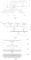
- a backlight module comprises a light guide plate 1 and a light source 2.
- Said light guide plate 1 comprises a transparent substrate 10 and a plurality of dimming units 11.
- the light source 2 is disposed on at least one side of said transparent substrate 10.
- the plurality of dimming units 11 is disposed on the lower surface of the transparent substrate 10.
- Each dimming unit 11 is used to adjust an emergent intensity of the light, which is incident from said light source 2 into said light guide plate, on the upper surface of said transparent substrate facing away from said dimming units 11.
- the light source is disposed on a side of the transparent substrate and a plurality of dimming units is disposed on the lower surface of the transparent substrate. Since each dimming unit is used to adjust an emergent intensity of the light, which is incident from said light source into said light guide plate, on the upper surface of said transparent substrate facing away from said dimming units, it enables the backlight module, when applied to a wear device, to set the number of dimming units according to a dimming partition requirement of the wear device such that partition adjustment of emergent light from the transparent substrate can be implemented by adjusting light incident into the transparent substrate using the respective dimming units according to the image demand when displaying an image, thereby enhancing the dimming performance of the backlight module, improving the light and shade contrast of the image displayed by the display device. As a result, detailed differences of images can be easily discriminated and the problem of dimming performance decline of a backlight module caused by a small amount of dimming partitions
- a backlight module provided in an embodiment of the present disclosure can be applied to display devices of conventional sizes in related arts, and to small-sized wear devices.
- the number of dimming units 11 can be set according to the number of dimming partitions 100 of the wear device, such that light incident into the transparent substrate 10 can be adjusted by using the respective dimming units 11 according to the image demand when displaying an image, and partition adjustment of emergent light from the transparent substrate 10 can be implemented, thereby enhancing the dimming performance of the backlight module.
- a good light and shade contrast of the images displayed by the wear device can be obtained and detailed differences of images can be easily discriminated.
- the problem of dimming performance decline of a backlight module caused by a small amount of dimming partitions 100 can be avoided.
- the light guide plate 1 is equivalent to a light guide sheet in related technology.
- a face of the transparent substrate 10 in the light guide plate 1 is disposed with a plurality of dimming units 11 thereon and the other face acts as a light exiting face.
- a light source is provided on a side of the light guide plate 1, and the light source can be disposed on at least one side of the transparent substrate 10 in the light guide plate 1.
- the four sides of the transparent substrate 10 can be provided with a light source simultaneously.
- the type of light source can be selected in accordance with the actual condition and conventionally a light bar 2 can be selected as a light source.
- each dimming unit 11 comprises a squeezing unit 111 and at least one elastic reflecting element 112 formed on a surface of a transparent substrate 10; the elastic reflecting element 112 is located between the squeezing unit 111 and the surface of a transparent substrate 10.
- the squeezing unit 111 applies a pressure towards said elastic reflecting element 112, and said elastic reflecting element 112 has an elastic deformation when the pressure is applied by said squeezing unit 111 and changes a contact area with said transparent substrate.
- Said squeezing degree represents a deformation degree of the elastic reflecting element after being squeezed.
- Step S11 When all elastic reflecting elements 112 are in a non-squeezing state, brightness of light from reflection of the light incident into the transparent substrate 10 by the elastic reflecting elements 112 is inhomogeneous, which results in complexity of adjustment of light brightness. Thus, a pressure applied by each squeezing unit 111 to corresponding elastic reflecting elements 112 needs to be adjusted such that the brightness of light from reflection of the light incident into the transparent substrate 10 by the respective elastic reflecting elements 112 is homogeneous (a homogeneous brightness is called a standard brightness).
- a squeezing degree of the elastic reflecting elements 112 at this time is used as a reference squeezing degree of the elastic reflecting elements 112, in this way, a correspondence relationship between a reference squeezing degree and brightness of reflected light is established.
- each of the squeezing units 111 needs to squeeze corresponding elastic reflecting elements 112 in accordance with an image dimming requirement, it only needs to determine a squeezing degree desired by each elastic reflecting element 112 according to a difference between a dimming brightness and the standard brightness.
- Step S12 Each squeezing unit 111 squeezes corresponding elastic reflecting elements 112 in accordance with an image dimming requirement.
- each squeezing unit 111 squeezing corresponding elastic reflecting elements 112 in accordance with an image dimming requirement comprises:
- the 6 squeezing units 111 are a first squeezing unit 1111, a second squeezing unit 1112, a third squeezing unit 1113, a fourth squeezing unit 1114, a fifth squeezing unit 1115 and a sixth squeezing unit 1116.
- the 22 elastic reflecting elements 112 are divided into 6 groups, including a first group of elastic reflecting elements (3 elastic reflecting elements), a second group of elastic reflecting elements (4 elastic reflecting elements), a third group of elastic reflecting elements (4 elastic reflecting elements), a fourth group of elastic reflecting elements (4 elastic reflecting elements), a fifth group of elastic reflecting elements (4 elastic reflecting elements) and a sixth group of elastic reflecting elements (3 elastic reflecting elements).
- the first squeezing unit 1111 is used to squeeze the first group of elastic reflecting elements
- the second squeezing unit 1112 is used to squeeze the second group of elastic reflecting elements
- the third squeezing unit 1113 is used to squeeze the third group of elastic reflecting elements
- the fourth squeezing unit 1114 is used to squeeze the fourth group of elastic reflecting elements
- the fifth squeezing unit 1115 is used to squeeze the fifth group of elastic reflecting elements
- the sixth squeezing unit 1116 is used to squeeze the sixth group of elastic reflecting elements.
- the pressure applied by the first squeezing unit 1111 to the first group of elastic reflecting elements is the greatest, embodied as the first group of elastic reflecting elements being flattened
- the pressure applied by the fourth squeezing unit 1114 to the fourth group of elastic reflecting elements is the second greatest, embodied as the fourth group of elastic reflecting elements being flattened by a lower degree than the first group of elastic reflecting elements being flattened
- the second squeezing unit 1112, the third squeezing unit 1113, the fifth squeezing unit 1115 and the sixth squeezing unit 1116 do not squeeze the corresponding second group of elastic reflecting elements, third group of elastic reflecting elements, fifth group of elastic reflecting elements, and sixth group of elastic reflecting elements.
- light intensity at a position of the transparent substrate 10 corresponding to the first group of elastic reflecting elements is the largest, that is, the light brightness is the highest;
- light intensity at a position of the transparent substrate 10 corresponding to the fourth group of elastic reflecting elements is the second largest, that is, the light brightness is the second highest;
- the positions of the transparent substrate 10 corresponding to the other groups of elastic reflecting elements are the smallest, that is, light brightness is the lowest.
- an elastic reflecting element 112 is located between the squeezing surface of the corresponding squeezing unit 111 and the surface of a transparent substrate 10, such that light incident into the transparent substrate 10 can be reflected by the elastic reflecting element 112 and exits from a surface of the transparent substrate 10 facing away from the plurality of elastic reflecting elements 112.
- the function of the plurality of elastic reflecting elements 112 is the same as the internal dots of a light guide plate.
- Each squeezing unit 111 and corresponding elastic reflecting elements 112 together form a dimming unit 11, each dimming unit 11 is used to adjust brightness of at least one pixel.
- a size of a squeezing surface of each squeezing unit 111 and the corresponding elastic reflecting elements 112 can be set in accordance with the image dimming requirement to match the number and positions of dimming units 11 with the number and positions of dimming partitions 100.
- the dimming performance of the backlight module can be enhanced, and a good light and shade contrast of the image displayed by the display device can be obtained so that detailed differences of images can be easily discriminated, thereby avoiding the problem of dimming performance decline of a backlight module caused by a small amount of dimming partitions 100.
- each of the squeezing units 111 can adjust a squeezing degree of corresponding elastic reflecting elements 112 independently, which enables each dimming unit 11 to adjust brightness of a corresponding pixel dynamically, thereby achieving the objective of dynamic dimming.
- each elastic reflecting element 112 on said transparent substrate 10 does not exceed a total area of 150 pixels of the display panel used in collaboration with the backlight module.
- the number of elastic reflecting elements 112 can be set in accordance with the dimming requirement.
- any two adjacent elastic reflecting elements 112 preferably so that any two adjacent elastic reflecting elements 112 just do not come into contact in a maximal squeezing state.
- the number of elastic reflecting elements 112 can be maximized and partition dimming can be better implemented.
- the force of friction between the elastic reflecting elements 112 and the transparent substrate 10 is not great, there might be the problem of displacement of an elastic reflecting element 112 when a squeezing unit 111 squeezes the elastic reflecting element 112, consequently, the squeezing degree of the elastic reflecting element 112 may not be adjusted in accordance with the actual demand although the squeezing unit 111 squeezes the elastic reflecting element 112.
- a plurality of elastic reflecting elements 112 can be disposed fixedly on the surface of the transparent substrate 10, and the specific manner can be bonding or other adhesive manners to ensure the positions of the elastic reflecting elements 112 fixed on the surface of the transparent substrate 10, thereby preventing the problem of displacement of an elastic reflecting element 112 when a squeezing unit 111 squeezes the elastic reflecting element 112.
- the shape of a squeezing surface of the squeezing unit 111 can be rectangular, round or hexagonal.
- a rigid transparent substrate is selected, and a common rigid transparent substrate includes a polymethyl methacrylate (abbreviated as PMMA) substrate or a common inorganic glass substrate.
- PMMA polymethyl methacrylate
- a plurality of elastic reflecting elements 112 can be arranged on the surface of the transparent substrate 10 uniformly.
- a surface of elastic reflecting element 112 is usually of a curved plane structure in order to avoid abrasion of the transparent substrate 10 when the elastic reflecting elements 112 are squeezed.
- an elastic sphere having a reflective surface can be selected, such as an elastic ellipsoid having a reflective surface or an elastic globe having a reflective surface.
- the elastic reflecting element 112 made of an elastic material having a reflecting property, such as an elastic reflecting element made of rubber, or an elastic reflecting element made of other elastic polymers.
- the color of the elastic reflecting element 112 is usually selected as white so that the light reflected from the elastic reflecting element 112 will not present different colors and the purity of color of the light is ensured.
- the plurality of elastic reflecting elements 112 may have a uniform size or different sizes. However, taking the convenience of manufacturing of the elastic reflecting elements 112 and the controllability of partition dimming into account, the sizes of the plurality of elastic reflecting elements 112 are preferably the same.
- an area of orthographic projection of the elastic reflecting element 112 on the transparent substrate 10 is different in different squeezing states, that is, the greater the pressure applied by the squeezing unit 111 on the corresponding elastic reflecting elements 112, the larger the area of orthographic projection of the elastic reflecting elements 112 on the transparent substrate 10, and the larger the area of contact between the elastic reflecting elements 112 and the transparent substrate 10.
- the surface of the elastic reflecting element 112 can be of a smooth structure or a coarse structure.
- the elastic reflecting element 112 When the surface of the elastic reflecting element 112 is a coarse structure, when light is reflected by the surface of the elastic reflecting element in contact with the transparent substrate, light is reflected in various directions by the coarse surface of the elastic reflecting element in contact with the transparent substrate and exits from the surface of said transparent substrate facing away from the elastic reflecting element in the form of scattering, thereby the elastic reflecting element implements a scattering function of dots on light and homogeneity of emergent light can be enhanced.
- any two adjacent elastic reflecting elements 112 may have a problem of interference under the maximal squeezing state, which results in displacement of the elastic reflecting element 112 being interfered.
- any two adjacent elastic reflecting elements 112 should have a gap under the maximal squeezing state to ensure that interference will not occur when any two adjacent elastic reflecting elements 112 are both under the maximal squeezing state and the elastic reflecting elements 112 come into contact with the transparent substrate 10 to the maximal extent under the maximal squeezing state.
- the elastic reflecting elements 112 coming into contact with the transparent substrate 10 to the maximal extent under a maximal squeezing state can ensure maximization of an adjusting range of light intensity by the elastic reflecting elements 112.
- a gap between any two adjacent elastic reflecting elements 112 under a maximal squeezing state cannot be big without a limit.
- the gap should make an orthographic projection of the gap on the transparent substrate 10 smaller than an orthographic projection of the elastic reflecting element 112 on the transparent substrate 10.
- a gap that keeps any two adjacent elastic reflecting elements 112 just not coming into contact under a maximal squeezing state is the best.
- the dimming units 11 in an embodiment of the present disclosure can be arranged freely or arranged in a matrix as shown in Fig. 2 , such that each said dimming unit is used to adjust brightness of at least one pixel of said display panel for use in collaboration with said backlight module.
- each said dimming unit is used to adjust brightness of at least one pixel of said display panel for use in collaboration with said backlight module.
- the squeezing units 111 in the embodiment of the present disclosure are in the arrangement of a matrix, such that light passing through the transparent substrate 10 presents dimming partitions 100 having a number and position corresponding to a number and position of the squeezing units 111, and the dimming partitions 100 are in an arrangement of a matrix to enable more even dimming.
- a pressure applied by a squeezing unit 111 to an elastic reflecting element 112 can be controlled through voltage.
- a squeezing unit 111 comprises a squeezing plate in contact with the elastic reflecting element 112 and may comprise an electrically driven pressure head (not shown) connected to said squeezing plate.
- the electrically driven pressure head is used to drive said squeezing plate to squeeze said elastic reflecting element 112, the electrically driven pressure head can drive the elastic reflecting element 112 based on the voltage.
- a backlight module provided in an embodiment of the present disclosure further comprises a pressure control unit 3 connected to the electrically driven pressure heads; wherein said pressure control unit 3 is configured to control a pressure of each electrically driven pressure head based on a dimming requirement of an image.
- a light source 2 provides light to the transparent substrate 10, light incident into the transparent substrate 10 is reflected by the elastic reflecting elements 112 and exits from surface of said transparent substrate facing away from said plurality of elastic reflecting elements 112.
- the pressure control unit 3 specifically comprises:
- each dimming unit 11 is used to adjust brightness of at least one pixel. Therefore, by using a voltage setting unit 32 to set a control voltage parameter for each electrically driven pressure head according to a grey scale display voltage, the pressure setting unit 33 can control a pressure applied to corresponding elastic reflecting elements 112 according to the control voltage parameter of each electrically driven pressure head.
- a dimming unit 11 formed by the elastic reflecting elements 112 corresponding to each electrically driven pressure head can be controlled to adjust pixel brightness to ensure the electrically driven pressure heads can squeeze corresponding elastic reflecting elements 112 accurately, thereby implementing precise partition dimming of the backlight module.
- a voltage setting unit 32 in an embodiment of the present disclosure obtains a grey scale voltage of each pixel from the grey scale display voltage; obtains a range of a control voltage parameter of an electrically driven pressure head corresponding to elastic reflecting elements 112 of each dimming unit 11 according to pixels corresponding to light to be adjusted by each dimming unit 11 and a grey scale voltage of each pixel; and sets a control voltage parameter of each electrically driven pressure head according to a range of control voltage parameter of each electrically driven pressure head.
- a pressure setting unit 33 in an embodiment of the present disclosure comprises:
- the pressure calculating module 332 obtains a relative pressure of each electrically driven pressure head based on a control voltage parameter of each electrically driven pressure head. Since the storage module 331 stores initial pressure of the electrically driven pressure heads, the initial pressure of the electrically driven pressure heads makes light incident into the transparent substrate 10 exhibit a homogeneous brightness after being reflected by the elastic reflecting elements 112, which is equivalent to a pressure applied by the electrically driven pressure heads to the corresponding elastic reflecting elements 112 in a white balance state. Thus, an actual pressure of each electrically driven pressure head can be obtained based on an initial pressure of each electrically driven pressure head and a relative pressure of the corresponding electrically driven pressure head.
- each dimming unit 11 in an embodiment of the present disclosure further comprises an elastic buffering plate 113 disposed on a side of a squeezing plate in proximity to an elastic sphere.
- a projection area of said elastic buffering plate on said transparent substrate covers a projection area of a squeezing face of said squeezing plate on said transparent substrate, such that buffering can be provided by the elastic buffering plate 113 when the electrically driven pressure head squeezes corresponding elastic reflecting elements 112, thereby avoiding abrasion of the surface of the elastic reflecting elements 112 caused by the electrically driven pressure head when squeezing the elastic reflecting elements 112 directly.
- any two any two adjacent elastic reflecting elements 112 have a gap under the maximal squeezing state, light may leak from the gap when irradiating onto the elastic reflecting elements 112.
- said elastic buffering plate 113 has a reflecting function, when the elastic buffering plate 113 forms a reflecting layer relative to the surface of the elastic reflecting elements 112, or the color of the surface can be set as white or silver to enhance the reflecting efficiency.
- the elastic buffering plate 113 may be made of a rubber material, a polypropylene material or other elastic polymer materials.
- An elastic buffering plate 113 in an embodiment of the present disclosure can be a separated type or an integrated type, as long as it can provide certain protection to the elastic reflecting elements 112 while ensuring no light leakage.
- the elastic buffering plate 113 included in the dimming unit 11 in the aforesaid embodiment has a reflecting function, there is no need to additionally arrange a reflecting plate in the backlight module provided by the embodiment of the present disclosure. In this way, unnecessary waste can be avoided and production cost can be reduced.
- a pressure control unit 3 provided in an embodiment of the present disclosure after being hardware implemented, can be integrated into a pressure control chip and connected to a grey scale correction unit 5 in a display control circuit.
- a pressure control unit 3 provided in an embodiment of the present disclosure after being hardware implemented, forms a pressure control terminal 4 as shown in Fig. 8 , comprising a transceiver 41, a storage 43 and a processor 42.
- the transceiver 41, the storage 43 and the processor 42 communicate via a bus 40.
- the transceiver 41 supports communication of the processor 42 with the grey scale correction unit 5 and the squeezing units 111 (a number of i squeezing units).
- the storage 43 stores a plurality of instructions to implement a control method implemented by the pressure control unit 3 in the embodiment of the present disclosure and can store initial pressure of the squeezing units 111.
- the processor 42 is used to execute the plurality of instructions to implement the control method of the pressure control unit.
- the processor 42 provided in the embodiment of the present disclosure can be a processor or a general term of a plurality of processing elements.
- the processor 42 may be a Central Processing Unit (CPU), or an Application Specific Integrated Circuit (ASIC), or one or more integrated circuit(s) configured as in the embodiments of the present disclosure, e.g. one or more digital signal processor (DSP), or one or more Field Programmable Gate Array (FPGA).
- CPU Central Processing Unit
- ASIC Application Specific Integrated Circuit
- DSP digital signal processor
- FPGA Field Programmable Gate Array
- the storage 43 can be a storage device or a general term for a plurality of storage elements used for storing executable program codes, etc.
- the storage 43 may include a random access memory (RAM), or a non-volatile memory, such as a disk memory or a Flash, etc.
- the bus 40 can be an Industry Standard Architecture (ISA) bus, a Peripheral Component Interconnect (PCI) bus or an Extended Industry Standard Architecture (EISA) bus, etc.
- ISA Industry Standard Architecture
- PCI Peripheral Component Interconnect
- EISA Extended Industry Standard Architecture
- the bus 40 can be divided into an address bus, a data bus and a control bus, etc. To facilitate illustration, the bus is illustrated with a bold line, but this does not indicate there is only one bus or one type of bus.
- An embodiment of the present disclosure further provides a method for controlling a backlight module, used to control a backlight module provided in the aforesaid embodiments, as shown in Fig. 1 , Fig. 7 and Fig. 9 , the method for controlling a backlight module comprises: a pressure controlling unit controlling a pressure of each electrically driven pressure head according to a dimming requirement of an image, such that light incident into the transparent substrate 10 is reflected by the respective elastic reflecting elements 112 and exits from a surface of the transparent substrate 10 facing away from the plurality of elastic reflecting elements 112.
- the method for controlling a backlight module provided in an embodiment of the present disclosure can obtain the same beneficial effects as the backlight module provided in the above technical solutions and are not repeated herein.
- controlling a pressure of each electrically driven pressure head according to a dimming requirement of an image comprises:
- setting a control voltage parameter for each electrically driven pressure head according to said grey scale display voltage comprises:
- a range of the control voltage parameter of the electrically driven pressure head corresponding to the elastic reflecting elements 112 of the current dimming unit 11 is a range between a maximum value of the grey scale voltage and a minimum value of the grey scale voltage of the three pixels.
- the control voltage parameter of the electrically driven pressure head corresponding to the elastic reflecting elements 112 of the current dimming unit 11 only needs to be between the maximum value and the minimum value of the grey scale voltage of the three pixels corresponding to the current dimming unit 11. For example, an average value of a sum of the grey scale voltages of the three pixels corresponding to the current dimming unit 11 can be selected as a control voltage parameter of the electrically driven pressure head corresponding to the elastic reflecting elements 112 of the current dimming unit 11.
- the method for controlling a backlight module provided in an embodiment of the present disclosure further comprises:
- setting a pressure for each electrically driven pressure head according to the control voltage parameter of each electrically driven pressure head comprises:
- An embodiment of the present disclosure further provides a display screen, comprising said backlight module and a display panel for use in collaboration with said backlight module, wherein said display panel is disposed on a light exiting face of said backlight module.
- the display panel is disposed on a surface of the transparent substrate 10 facing away from the dimming unit 11.
- each dimming unit is used to adjust brightness of at least one pixel of said display panel for use in collaboration with said backlight module.
- Each dimming unit comprises a squeezing unit and at least one elastic reflecting element located between said squeezing unit and a surface of said transparent substrate; and wherein said squeezing unit applies a pressure towards said elastic reflecting element, wherein said elastic reflecting element has an elastic deformation when a pressure is applied by said squeezing unit and changes a contact area with said transparent substrate.
- a coverage area of each elastic reflecting element on said transparent substrate does not exceed a total area of 150 pixels of the display panel.
- the display screen provided in an embodiment of the present disclosure can obtain the same beneficial effects as the backlight module provided in the above technical solutions and are not repeated herein.
- An embodiment of the present disclosure further provides a wear device including a display screen provided in the aforesaid embodiment.
- the wear device provided in the embodiment of the present disclosure can obtain the same beneficial effects as the backlight module provided in the above technical solutions and are not repeated herein.
- the wear device provided in the embodiment of the present disclosure can be an AR wear device, or a VR wear display device, or any other wear devices having a display function.
Landscapes
- Physics & Mathematics (AREA)
- General Physics & Mathematics (AREA)
- Optics & Photonics (AREA)
- Engineering & Computer Science (AREA)
- Nonlinear Science (AREA)
- Computer Hardware Design (AREA)
- Theoretical Computer Science (AREA)
- Mathematical Physics (AREA)
- Chemical & Material Sciences (AREA)
- Crystallography & Structural Chemistry (AREA)
- Planar Illumination Modules (AREA)
Claims (13)
- Hintergrundbeleuchtungsmodul, das eine Lichtquelle und eine Lichtleitplatte (1) umfasst, wobei die Lichtleitplatte (1) ein transparentes Substrat (10) und eine Vielzahl von Dimmeinheiten (11) umfasst, die eine Reflexionsfunktion aufweisen, wobei die Lichtquelle an mindestens einer Seite des transparenten Substrats (10) angeordnet ist und die Vielzahl von Dimmeinheiten (11) an einer unteren Oberfläche des transparenten Substrats (10) angeordnet und angepasst ist, um die Stärke des Lichts, das von der Lichtquelle in die Lichtleitplatte (1) einfällt und aus einer oberen Oberfläche des transparenten Substrats (10), die von den Dimmeinheiten (11) abgewandt ist, austritt, einzustellen,wobei das Hintergrundbeleuchtungsmodul eine Vielzahl elastischer Reflexionselemente (112) umfasst und mindestens eine der Dimmeinheiten (11) eine Quetscheinheit (111) und mindestens ein elastisches Reflexionselement (112) umfasst, das zwischen der Quetscheinheit (111) und einer Oberfläche des transparenten Substrats (10) liegt; die Quetscheinheit (111) konfiguriert ist, um einen Druck in Richtung des elastischen Reflexionselements (112) auszuüben, das elastische Reflexionselement (112) konfiguriert ist, um eine elastische Verformung zu erzeugen, wenn der Druck von der Quetscheinheit (111) bereitgestellt wird, und eine Kontaktfläche mit dem transparenten Substrat (10) zu ändern, undwobei das elastische Reflexionselement (112) eine elastische Kugel ist, die eine reflektierende Oberfläche aufweist, und zwei aneinandergrenzende elastische Reflexionselemente einen Zwischenraum dazwischen aufweisen.
- Hintergrundbeleuchtungsmodul nach Anspruch 1, wobei die Dimmeinheiten (11) in einer Matrix auf dem transparenten Substrat (10) verteilt sind.
- Hintergrundbeleuchtungsmodul nach Anspruch 1, wobei die Quetscheinheit (111) eine Quetschplatte in Kontakt mit dem mindestens einen elastischen Reflexionselement (112) und einen elektrisch angetriebenen Druckkopf umfasst, der mit der Quetschplatte verbunden ist, wobei der elektrisch angetriebene Druckkopf konfiguriert ist, um die Quetschplatte anzutreiben, um das elastische Reflexionselement (112) zu quetschen.
- Hintergrundbeleuchtungsmodul nach Anspruch 3, wobei das Hintergrundbeleuchtungsmodul ferner eine Drucksteuereinheit (3) umfasst, die mit jedem elektrisch angetriebenen Druckkopf verbunden ist;
wobei die Drucksteuereinheit (3) konfiguriert ist, um einen Druck jedes elektrisch angetriebenen Druckkopfs basierend auf einer Dimmanforderung zu steuern. - Hintergrundbeleuchtungsmodul nach Anspruch 4, wobei die Drucksteuereinheit (3) Folgendes umfasst:eine Empfangseinheit (31), die mit einer Graustufen-Korrektureinheit (5) verbunden und konfiguriert ist, um eine Graustufen-Anzeigespannung zu empfangen;eine Spannungseinstelleinheit (32), die konfiguriert ist, um einen Steuerspannungsparameter für jeden elektrisch angetriebenen Druckkopf gemäß der Graustufen-Anzeigespannung einzustellen;eine Druckeinstelleinheit (33), die konfiguriert ist, um einen Druck für jeden elektrisch angetriebenen Druckkopf gemäß dem Steuerspannungsparameter für jeden elektrisch angetriebenen Druckkopf einzustellen und eine Antriebsspannung für jeden elektrisch angetriebenen Druckkopf gemäß dem Druck jedes elektrisch angetriebenen Druckkopfs einzustellen.
- Hintergrundbeleuchtungsmodul nach Anspruch 5, wobei die Druckeinstelleinheit (33) Folgendes umfasst:ein Speichermodul (331), das konfiguriert ist, um einen anfänglichen Druck jedes elektrisch angetriebenen Druckkopfs zu speichern; wobei der anfängliche Druck jedes elektrisch angetriebenen Druckkopfs die Helligkeit des Lichts, das in das transparente Substrat (10) einfällt, homogen macht, nachdem es von den elastischen Reflexionselementen (112) reflektiert wurde;ein Druckberechnungsmodul (332), das konfiguriert ist, um einen relativen Druck jedes elektrisch angetriebenen Druckkopfs gemäß einem Steuerspannungsparameter jedes elektrisch angetriebenen Druckkopfs zu erhalten und um einen Druck jedes elektrisch angetriebenen Druckkopfs gemäß einem anfänglichen Druck jedes elektrisch angetriebenen Druckkopfs und einem relativen Druck des entsprechenden elektrisch angetriebenen Druckkopfs zu erhalten.
- Hintergrundbeleuchtungsmodul nach einem der Ansprüche 3-6, das ferner eine elastische Pufferplatte (113) umfasst, die an einer Seite der Quetschplatte in der Nähe des elastischen reflektierenden Elements (112) angeordnet ist, wobei eine Projektionsfläche der elastischen Pufferplatte (113) an dem transparenten Substrat (10) eine Projektionsfläche einer Quetschfläche der Quetschplatte an dem transparenten Substrat (10) bedeckt, und die elastische Pufferplatte (113) eine Reflexionsfunktion aufweist.
- Anzeigebildschirm, der das Hintergrundbeleuchtungsmodul nach Anspruch 1 und eine Anzeigetafel zur Verwendung in Zusammenarbeit mit dem Hintergrundbeleuchtungsmodul umfasst, wobei die Anzeigetafel an einer Lichtaustrittsseite des Hintergrundbeleuchtungsmoduls angeordnet ist.
- Anzeigebildschirm nach Anspruch 8, wobei mindestens eine der Dimmeinheiten (11) konfiguriert ist, um die Helligkeit mindestens eines Pixels der Anzeigetafel einzustellen.
- Anzeigebildschirm nach Anspruch 8, wobei mindestens eine der Dimmeinheiten (11) eine Quetscheinheit (111) und mindestens ein elastisches Reflexionselement (112) umfasst, das zwischen der Quetscheinheit (111) und einer Oberfläche des transparenten Substrats (10) liegt; wobei die Quetscheinheit (111) konfiguriert ist, um einen Druck in Richtung des elastischen Reflexionselements (112) bereitzustellen, wobei das elastische Reflexionselement (112) konfiguriert ist, um eine elastische Verformung zu erzeugen, wenn der Druck von der Quetscheinheit (111) bereitgestellt wird, und eine Kontaktfläche mit dem transparenten Substrat (10) zu ändern.
- Tragevorrichtung, die den Anzeigebildschirm nach einem der Ansprüche 8-10 umfasst.
- Verfahren zum Steuern eines Hintergrundbeleuchtungsmoduls nach einem der Ansprüche 4-6, das Folgendes umfasst:Empfangen einer Graustufen-Anzeigespannung;Einstellen eines Steuerspannungsparameters für jeden elektrisch angetriebenen Druckkopf gemäß der Graustufen-Anzeigespannung;Einstellen eines Drucks für jeden elektrisch angetriebenen Druckkopf gemäß dem Steuerspannungsparameter für jeden elektrisch angetriebenen Druckkopf, und Einstellen einer Antriebsspannung für jeden elektrisch angetriebenen Druckkopf gemäß dem Druck jedes elektrisch angetriebenen Druckkopfs.
- Verfahren zum Steuern eines Hintergrundbeleuchtungsmoduls nach Anspruch 12, wobei
vor dem Empfangen einer Graustufen-Anzeigespannung das Verfahren zum Steuern eines Hintergrundbeleuchtungsmoduls ferner Folgendes umfasst:Speichern eines anfänglichen Drucks jedes elektrisch angetriebenen Druckkopfs, wobei der anfängliche Druck jedes elektrisch angetriebenen Druckkopfs die Helligkeit des Lichts steuert, das in das transparente Substrat einfällt, um homogen zu sein, nachdem es von den elastischen Reflexionselementen reflektiert wurde;wobei das Einstellen eines Drucks für jeden elektrisch angetriebenen Druckkopf gemäß dem Steuerspannungsparameter für jeden elektrisch angetriebenen Druckkopf Folgendes umfasst:Erhalten eines relativen Drucks jedes elektrisch angetriebenen Druckkopfs gemäß dem Steuerspannungsparameter jedes elektrisch angetriebenen Druckkopfs;Erhalten eines Drucks jedes elektrisch angetriebenen Druckkopfs gemäß dem anfänglichen Druck jedes elektrisch angetriebenen Druckkopfs und dem relativen Druck des entsprechenden elektrisch angetriebenen Druckkopfs.
Applications Claiming Priority (2)
| Application Number | Priority Date | Filing Date | Title |
|---|---|---|---|
| CN201810111114.1A CN110133790B (zh) | 2018-02-02 | 2018-02-02 | 一种背光模组及控制方法、穿戴设备 |
| PCT/CN2018/111209 WO2019148897A1 (zh) | 2018-02-02 | 2018-10-22 | 背光模组及控制方法、显示屏和穿戴设备 |
Publications (3)
| Publication Number | Publication Date |
|---|---|
| EP3748423A1 EP3748423A1 (de) | 2020-12-09 |
| EP3748423A4 EP3748423A4 (de) | 2021-10-20 |
| EP3748423B1 true EP3748423B1 (de) | 2023-05-24 |
Family
ID=67478597
Family Applications (1)
| Application Number | Title | Priority Date | Filing Date |
|---|---|---|---|
| EP18859947.6A Active EP3748423B1 (de) | 2018-02-02 | 2018-10-22 | Hintergrundbeleuchtungsmodul, steuerungsverfahren, bildschirm und wearable-vorrichtung |
Country Status (4)
| Country | Link |
|---|---|
| US (1) | US10796646B2 (de) |
| EP (1) | EP3748423B1 (de) |
| CN (1) | CN110133790B (de) |
| WO (1) | WO2019148897A1 (de) |
Families Citing this family (1)
| Publication number | Priority date | Publication date | Assignee | Title |
|---|---|---|---|---|
| CN115032831B (zh) * | 2022-04-29 | 2023-06-13 | 荣耀终端有限公司 | 一种显示设备 |
Family Cites Families (21)
| Publication number | Priority date | Publication date | Assignee | Title |
|---|---|---|---|---|
| JP4348409B2 (ja) * | 2001-02-27 | 2009-10-21 | ドルビー ラボラトリーズ ライセンシング コーポレイション | 高ダイナミック・レンジ表示装置 |
| US7484857B2 (en) * | 2004-11-30 | 2009-02-03 | Massachusetts Institute Of Technology | Light modulating mirror device and array |
| JP2007034120A (ja) * | 2005-07-29 | 2007-02-08 | Sharp Corp | 直下式バックライト装置および直下式バックライト装置を用いた液晶表示装置 |
| US20100214208A1 (en) * | 2005-12-27 | 2010-08-26 | Tatsuo Itoh | Planar lighting device and liquid crystal display device |
| US7486854B2 (en) * | 2006-01-24 | 2009-02-03 | Uni-Pixel Displays, Inc. | Optical microstructures for light extraction and control |
| KR101329139B1 (ko) * | 2007-10-12 | 2013-11-14 | 삼성전자주식회사 | 투과/반투과/반사 모드를 구현하는 스위칭 디스플레이 제어시스템 및 방법 |
| KR101509564B1 (ko) * | 2008-11-28 | 2015-04-06 | 삼성전자주식회사 | 분할 휘도 조절 기능을 갖는 측면형 백라이트 유닛 |
| CN102708812B (zh) * | 2011-04-22 | 2014-05-07 | 京东方科技集团股份有限公司 | 液晶显示器的局部调光方法、液晶显示器及其背光系统 |
| JP2015092434A (ja) * | 2012-02-24 | 2015-05-14 | シャープ株式会社 | バックライトユニット及び液晶表示装置 |
| JP6080429B2 (ja) * | 2012-08-24 | 2017-02-15 | キヤノン株式会社 | 光源装置、光源装置の制御方法、及び、表示装置 |
| US20140240207A1 (en) * | 2013-02-27 | 2014-08-28 | Motorola Mobility Llc | Low-power display and corresponding lighting apparatus and methods of operation |
| CA2890373C (en) * | 2013-10-20 | 2022-04-12 | Mtt Innovation Incorporated | Light field projectors and methods |
| US9696482B2 (en) * | 2013-12-30 | 2017-07-04 | Google Technology Holdings LLC | Backlight dimming film |
| JP6791840B2 (ja) * | 2014-08-14 | 2020-11-25 | エムティティ イノベーション インコーポレイテッドMtt Innovation Incorporated | 光源 |
| TWI526740B (zh) * | 2014-09-11 | 2016-03-21 | 友達光電股份有限公司 | 薄型背光模組 |
| CN106291800B (zh) * | 2016-10-27 | 2019-05-10 | 京东方科技集团股份有限公司 | 一种显示装置的调光结构、背光模组和显示装置 |
| CN106405880B (zh) * | 2016-11-21 | 2019-03-19 | 青岛海信电器股份有限公司 | 磁致折射率调节材料、膜、导光板、背光模组及显示设备 |
| CN206684435U (zh) * | 2017-04-11 | 2017-11-28 | 上海向隆电子科技有限公司 | 具有区段调光功效的背光模组 |
| CN107315283B (zh) * | 2017-08-17 | 2021-03-05 | 京东方科技集团股份有限公司 | 背光模组、显示装置和调节背光模组出光亮度的方法 |
| TWI641975B (zh) * | 2017-08-24 | 2018-11-21 | 友達光電股份有限公司 | 顯示面板 |
| CN107589594B (zh) * | 2017-09-25 | 2021-01-26 | 京东方科技集团股份有限公司 | 一种可调反射装置、背光模组及显示装置 |
-
2018
- 2018-02-02 CN CN201810111114.1A patent/CN110133790B/zh active Active
- 2018-10-22 US US16/338,712 patent/US10796646B2/en active Active
- 2018-10-22 EP EP18859947.6A patent/EP3748423B1/de active Active
- 2018-10-22 WO PCT/CN2018/111209 patent/WO2019148897A1/zh not_active Ceased
Also Published As
| Publication number | Publication date |
|---|---|
| WO2019148897A1 (zh) | 2019-08-08 |
| CN110133790B (zh) | 2020-07-31 |
| EP3748423A1 (de) | 2020-12-09 |
| US10796646B2 (en) | 2020-10-06 |
| EP3748423A4 (de) | 2021-10-20 |
| US20190266957A1 (en) | 2019-08-29 |
| CN110133790A (zh) | 2019-08-16 |
Similar Documents
| Publication | Publication Date | Title |
|---|---|---|
| CN105511179B (zh) | 一种液晶显示器 | |
| US7742239B2 (en) | Method to control point spread function of an image | |
| US9645443B2 (en) | Reflective liquid-crystal display device and electronic apparatus | |
| CN105579900B (zh) | 用于前光半后向反射显示器的方法和装置 | |
| JP6877910B2 (ja) | 表示装置 | |
| JP4600269B2 (ja) | 液晶表示装置 | |
| KR102130280B1 (ko) | 곡면 백라이트 유닛 및 이를 포함하는 곡면 디스플레이 장치 | |
| CN101196649B (zh) | 显示装置 | |
| CN105549266B (zh) | 一种液晶显示器 | |
| TW201833638A (zh) | 具有顏色定制射出圖案的多光束背光板、顯示器及方法 | |
| CN105652490B (zh) | 一种显示眼镜及其驱动方法 | |
| JPH11513814A (ja) | 液晶ディスプレイ内に組み込んだ、ホログラフ高コントラスト視野スクリーン | |
| TW202024747A (zh) | 具有光罩元件的多視域背光件、顯示器和方法 | |
| US20150268478A1 (en) | Display device | |
| WO2010095743A1 (ja) | 表示素子、及び電気機器 | |
| TWI770606B (zh) | 使用反射式多光束元件的多視像背光件、多視像顯示器和方法 | |
| US20250224622A1 (en) | 2d/multiview switchable lenticular display, system, and method | |
| TW202217411A (zh) | 具有微縫隙多光束元件的多視像背光件、多視像顯示器及其方法 | |
| US20120133690A1 (en) | Display element and electrical device | |
| TWI864483B (zh) | 時間多工多視像背光件、多視像顯示器及其方法 | |
| US10796646B2 (en) | Backlight module and control method, display screen and wearable device | |
| JP2003084143A (ja) | 輝度強化導光板及びこれを適用した液晶表示装置 | |
| KR102444400B1 (ko) | 양면 표시장치 및 그를 위한 백라이트 유닛 | |
| US11509882B2 (en) | Three-dimensional display apparatus and virtual reality device | |
| KR102050433B1 (ko) | 액정표시장치 |
Legal Events
| Date | Code | Title | Description |
|---|---|---|---|
| STAA | Information on the status of an ep patent application or granted ep patent |
Free format text: STATUS: UNKNOWN |
|
| STAA | Information on the status of an ep patent application or granted ep patent |
Free format text: STATUS: THE INTERNATIONAL PUBLICATION HAS BEEN MADE |
|
| PUAI | Public reference made under article 153(3) epc to a published international application that has entered the european phase |
Free format text: ORIGINAL CODE: 0009012 |
|
| STAA | Information on the status of an ep patent application or granted ep patent |
Free format text: STATUS: REQUEST FOR EXAMINATION WAS MADE |
|
| 17P | Request for examination filed |
Effective date: 20200203 |
|
| AK | Designated contracting states |
Kind code of ref document: A1 Designated state(s): AL AT BE BG CH CY CZ DE DK EE ES FI FR GB GR HR HU IE IS IT LI LT LU LV MC MK MT NL NO PL PT RO RS SE SI SK SM TR |
|
| AX | Request for extension of the european patent |
Extension state: BA ME |
|
| DAV | Request for validation of the european patent (deleted) | ||
| DAX | Request for extension of the european patent (deleted) | ||
| A4 | Supplementary search report drawn up and despatched |
Effective date: 20210921 |
|
| RIC1 | Information provided on ipc code assigned before grant |
Ipc: F21V 8/00 20060101ALI20210915BHEP Ipc: G02F 1/13357 20060101AFI20210915BHEP |
|
| GRAP | Despatch of communication of intention to grant a patent |
Free format text: ORIGINAL CODE: EPIDOSNIGR1 |
|
| STAA | Information on the status of an ep patent application or granted ep patent |
Free format text: STATUS: GRANT OF PATENT IS INTENDED |
|
| INTG | Intention to grant announced |
Effective date: 20230217 |
|
| GRAS | Grant fee paid |
Free format text: ORIGINAL CODE: EPIDOSNIGR3 |
|
| GRAA | (expected) grant |
Free format text: ORIGINAL CODE: 0009210 |
|
| STAA | Information on the status of an ep patent application or granted ep patent |
Free format text: STATUS: THE PATENT HAS BEEN GRANTED |
|
| AK | Designated contracting states |
Kind code of ref document: B1 Designated state(s): AL AT BE BG CH CY CZ DE DK EE ES FI FR GB GR HR HU IE IS IT LI LT LU LV MC MK MT NL NO PL PT RO RS SE SI SK SM TR |
|
| REG | Reference to a national code |
Ref country code: GB Ref legal event code: FG4D |
|
| REG | Reference to a national code |
Ref country code: CH Ref legal event code: EP |
|
| REG | Reference to a national code |
Ref country code: DE Ref legal event code: R096 Ref document number: 602018050313 Country of ref document: DE |
|
| REG | Reference to a national code |
Ref country code: AT Ref legal event code: REF Ref document number: 1569884 Country of ref document: AT Kind code of ref document: T Effective date: 20230615 |
|
| REG | Reference to a national code |
Ref country code: IE Ref legal event code: FG4D |
|
| REG | Reference to a national code |
Ref country code: LT Ref legal event code: MG9D |
|
| REG | Reference to a national code |
Ref country code: NL Ref legal event code: MP Effective date: 20230524 |
|
| REG | Reference to a national code |
Ref country code: AT Ref legal event code: MK05 Ref document number: 1569884 Country of ref document: AT Kind code of ref document: T Effective date: 20230524 |
|
| PG25 | Lapsed in a contracting state [announced via postgrant information from national office to epo] |
Ref country code: SE Free format text: LAPSE BECAUSE OF FAILURE TO SUBMIT A TRANSLATION OF THE DESCRIPTION OR TO PAY THE FEE WITHIN THE PRESCRIBED TIME-LIMIT Effective date: 20230524 Ref country code: PT Free format text: LAPSE BECAUSE OF FAILURE TO SUBMIT A TRANSLATION OF THE DESCRIPTION OR TO PAY THE FEE WITHIN THE PRESCRIBED TIME-LIMIT Effective date: 20230925 Ref country code: NO Free format text: LAPSE BECAUSE OF FAILURE TO SUBMIT A TRANSLATION OF THE DESCRIPTION OR TO PAY THE FEE WITHIN THE PRESCRIBED TIME-LIMIT Effective date: 20230824 Ref country code: NL Free format text: LAPSE BECAUSE OF FAILURE TO SUBMIT A TRANSLATION OF THE DESCRIPTION OR TO PAY THE FEE WITHIN THE PRESCRIBED TIME-LIMIT Effective date: 20230524 Ref country code: ES Free format text: LAPSE BECAUSE OF FAILURE TO SUBMIT A TRANSLATION OF THE DESCRIPTION OR TO PAY THE FEE WITHIN THE PRESCRIBED TIME-LIMIT Effective date: 20230524 Ref country code: AT Free format text: LAPSE BECAUSE OF FAILURE TO SUBMIT A TRANSLATION OF THE DESCRIPTION OR TO PAY THE FEE WITHIN THE PRESCRIBED TIME-LIMIT Effective date: 20230524 |
|
| PG25 | Lapsed in a contracting state [announced via postgrant information from national office to epo] |
Ref country code: RS Free format text: LAPSE BECAUSE OF FAILURE TO SUBMIT A TRANSLATION OF THE DESCRIPTION OR TO PAY THE FEE WITHIN THE PRESCRIBED TIME-LIMIT Effective date: 20230524 Ref country code: PL Free format text: LAPSE BECAUSE OF FAILURE TO SUBMIT A TRANSLATION OF THE DESCRIPTION OR TO PAY THE FEE WITHIN THE PRESCRIBED TIME-LIMIT Effective date: 20230524 Ref country code: LV Free format text: LAPSE BECAUSE OF FAILURE TO SUBMIT A TRANSLATION OF THE DESCRIPTION OR TO PAY THE FEE WITHIN THE PRESCRIBED TIME-LIMIT Effective date: 20230524 Ref country code: LT Free format text: LAPSE BECAUSE OF FAILURE TO SUBMIT A TRANSLATION OF THE DESCRIPTION OR TO PAY THE FEE WITHIN THE PRESCRIBED TIME-LIMIT Effective date: 20230524 Ref country code: IS Free format text: LAPSE BECAUSE OF FAILURE TO SUBMIT A TRANSLATION OF THE DESCRIPTION OR TO PAY THE FEE WITHIN THE PRESCRIBED TIME-LIMIT Effective date: 20230924 Ref country code: HR Free format text: LAPSE BECAUSE OF FAILURE TO SUBMIT A TRANSLATION OF THE DESCRIPTION OR TO PAY THE FEE WITHIN THE PRESCRIBED TIME-LIMIT Effective date: 20230524 Ref country code: GR Free format text: LAPSE BECAUSE OF FAILURE TO SUBMIT A TRANSLATION OF THE DESCRIPTION OR TO PAY THE FEE WITHIN THE PRESCRIBED TIME-LIMIT Effective date: 20230825 |
|
| PG25 | Lapsed in a contracting state [announced via postgrant information from national office to epo] |
Ref country code: FI Free format text: LAPSE BECAUSE OF FAILURE TO SUBMIT A TRANSLATION OF THE DESCRIPTION OR TO PAY THE FEE WITHIN THE PRESCRIBED TIME-LIMIT Effective date: 20230524 |
|
| PG25 | Lapsed in a contracting state [announced via postgrant information from national office to epo] |
Ref country code: SK Free format text: LAPSE BECAUSE OF FAILURE TO SUBMIT A TRANSLATION OF THE DESCRIPTION OR TO PAY THE FEE WITHIN THE PRESCRIBED TIME-LIMIT Effective date: 20230524 |
|
| PG25 | Lapsed in a contracting state [announced via postgrant information from national office to epo] |
Ref country code: SM Free format text: LAPSE BECAUSE OF FAILURE TO SUBMIT A TRANSLATION OF THE DESCRIPTION OR TO PAY THE FEE WITHIN THE PRESCRIBED TIME-LIMIT Effective date: 20230524 Ref country code: SK Free format text: LAPSE BECAUSE OF FAILURE TO SUBMIT A TRANSLATION OF THE DESCRIPTION OR TO PAY THE FEE WITHIN THE PRESCRIBED TIME-LIMIT Effective date: 20230524 Ref country code: RO Free format text: LAPSE BECAUSE OF FAILURE TO SUBMIT A TRANSLATION OF THE DESCRIPTION OR TO PAY THE FEE WITHIN THE PRESCRIBED TIME-LIMIT Effective date: 20230524 Ref country code: EE Free format text: LAPSE BECAUSE OF FAILURE TO SUBMIT A TRANSLATION OF THE DESCRIPTION OR TO PAY THE FEE WITHIN THE PRESCRIBED TIME-LIMIT Effective date: 20230524 Ref country code: DK Free format text: LAPSE BECAUSE OF FAILURE TO SUBMIT A TRANSLATION OF THE DESCRIPTION OR TO PAY THE FEE WITHIN THE PRESCRIBED TIME-LIMIT Effective date: 20230524 Ref country code: CZ Free format text: LAPSE BECAUSE OF FAILURE TO SUBMIT A TRANSLATION OF THE DESCRIPTION OR TO PAY THE FEE WITHIN THE PRESCRIBED TIME-LIMIT Effective date: 20230524 |
|
| REG | Reference to a national code |
Ref country code: DE Ref legal event code: R097 Ref document number: 602018050313 Country of ref document: DE |
|
| PLBE | No opposition filed within time limit |
Free format text: ORIGINAL CODE: 0009261 |
|
| STAA | Information on the status of an ep patent application or granted ep patent |
Free format text: STATUS: NO OPPOSITION FILED WITHIN TIME LIMIT |
|
| 26N | No opposition filed |
Effective date: 20240227 |
|
| PG25 | Lapsed in a contracting state [announced via postgrant information from national office to epo] |
Ref country code: SI Free format text: LAPSE BECAUSE OF FAILURE TO SUBMIT A TRANSLATION OF THE DESCRIPTION OR TO PAY THE FEE WITHIN THE PRESCRIBED TIME-LIMIT Effective date: 20230524 |
|
| PG25 | Lapsed in a contracting state [announced via postgrant information from national office to epo] |
Ref country code: MC Free format text: LAPSE BECAUSE OF FAILURE TO SUBMIT A TRANSLATION OF THE DESCRIPTION OR TO PAY THE FEE WITHIN THE PRESCRIBED TIME-LIMIT Effective date: 20230524 Ref country code: SI Free format text: LAPSE BECAUSE OF FAILURE TO SUBMIT A TRANSLATION OF THE DESCRIPTION OR TO PAY THE FEE WITHIN THE PRESCRIBED TIME-LIMIT Effective date: 20230524 Ref country code: IT Free format text: LAPSE BECAUSE OF FAILURE TO SUBMIT A TRANSLATION OF THE DESCRIPTION OR TO PAY THE FEE WITHIN THE PRESCRIBED TIME-LIMIT Effective date: 20230524 |
|
| REG | Reference to a national code |
Ref country code: CH Ref legal event code: PL |
|
| REG | Reference to a national code |
Ref country code: BE Ref legal event code: MM Effective date: 20231031 |
|
| PG25 | Lapsed in a contracting state [announced via postgrant information from national office to epo] |
Ref country code: LU Free format text: LAPSE BECAUSE OF NON-PAYMENT OF DUE FEES Effective date: 20231022 |
|
| GBPC | Gb: european patent ceased through non-payment of renewal fee |
Effective date: 20231022 |
|
| PG25 | Lapsed in a contracting state [announced via postgrant information from national office to epo] |
Ref country code: LU Free format text: LAPSE BECAUSE OF NON-PAYMENT OF DUE FEES Effective date: 20231022 |
|
| PG25 | Lapsed in a contracting state [announced via postgrant information from national office to epo] |
Ref country code: GB Free format text: LAPSE BECAUSE OF NON-PAYMENT OF DUE FEES Effective date: 20231022 |
|
| PG25 | Lapsed in a contracting state [announced via postgrant information from national office to epo] |
Ref country code: CH Free format text: LAPSE BECAUSE OF NON-PAYMENT OF DUE FEES Effective date: 20231031 |
|
| PG25 | Lapsed in a contracting state [announced via postgrant information from national office to epo] |
Ref country code: GB Free format text: LAPSE BECAUSE OF NON-PAYMENT OF DUE FEES Effective date: 20231022 Ref country code: FR Free format text: LAPSE BECAUSE OF NON-PAYMENT OF DUE FEES Effective date: 20231031 Ref country code: CH Free format text: LAPSE BECAUSE OF NON-PAYMENT OF DUE FEES Effective date: 20231031 |
|
| PG25 | Lapsed in a contracting state [announced via postgrant information from national office to epo] |
Ref country code: BE Free format text: LAPSE BECAUSE OF NON-PAYMENT OF DUE FEES Effective date: 20231031 |
|
| PG25 | Lapsed in a contracting state [announced via postgrant information from national office to epo] |
Ref country code: IE Free format text: LAPSE BECAUSE OF NON-PAYMENT OF DUE FEES Effective date: 20231022 |
|
| PG25 | Lapsed in a contracting state [announced via postgrant information from national office to epo] |
Ref country code: IE Free format text: LAPSE BECAUSE OF NON-PAYMENT OF DUE FEES Effective date: 20231022 |
|
| PG25 | Lapsed in a contracting state [announced via postgrant information from national office to epo] |
Ref country code: BG Free format text: LAPSE BECAUSE OF FAILURE TO SUBMIT A TRANSLATION OF THE DESCRIPTION OR TO PAY THE FEE WITHIN THE PRESCRIBED TIME-LIMIT Effective date: 20230524 |
|
| PG25 | Lapsed in a contracting state [announced via postgrant information from national office to epo] |
Ref country code: BG Free format text: LAPSE BECAUSE OF FAILURE TO SUBMIT A TRANSLATION OF THE DESCRIPTION OR TO PAY THE FEE WITHIN THE PRESCRIBED TIME-LIMIT Effective date: 20230524 |
|
| PG25 | Lapsed in a contracting state [announced via postgrant information from national office to epo] |
Ref country code: CY Free format text: LAPSE BECAUSE OF FAILURE TO SUBMIT A TRANSLATION OF THE DESCRIPTION OR TO PAY THE FEE WITHIN THE PRESCRIBED TIME-LIMIT; INVALID AB INITIO Effective date: 20181022 |
|
| PG25 | Lapsed in a contracting state [announced via postgrant information from national office to epo] |
Ref country code: HU Free format text: LAPSE BECAUSE OF FAILURE TO SUBMIT A TRANSLATION OF THE DESCRIPTION OR TO PAY THE FEE WITHIN THE PRESCRIBED TIME-LIMIT; INVALID AB INITIO Effective date: 20181022 |
|
| PG25 | Lapsed in a contracting state [announced via postgrant information from national office to epo] |
Ref country code: TR Free format text: LAPSE BECAUSE OF FAILURE TO SUBMIT A TRANSLATION OF THE DESCRIPTION OR TO PAY THE FEE WITHIN THE PRESCRIBED TIME-LIMIT Effective date: 20230524 |
|
| PGFP | Annual fee paid to national office [announced via postgrant information from national office to epo] |
Ref country code: DE Payment date: 20251021 Year of fee payment: 8 |