EP3747655A1 - Druckkopf und verfahren zur herstellung eines druckkopfs - Google Patents
Druckkopf und verfahren zur herstellung eines druckkopfs Download PDFInfo
- Publication number
- EP3747655A1 EP3747655A1 EP20177800.8A EP20177800A EP3747655A1 EP 3747655 A1 EP3747655 A1 EP 3747655A1 EP 20177800 A EP20177800 A EP 20177800A EP 3747655 A1 EP3747655 A1 EP 3747655A1
- Authority
- EP
- European Patent Office
- Prior art keywords
- output
- print head
- medium
- filter
- Prior art date
- Legal status (The legal status is an assumption and is not a legal conclusion. Google has not performed a legal analysis and makes no representation as to the accuracy of the status listed.)
- Granted
Links
Images


Classifications
-
- B—PERFORMING OPERATIONS; TRANSPORTING
- B41—PRINTING; LINING MACHINES; TYPEWRITERS; STAMPS
- B41J—TYPEWRITERS; SELECTIVE PRINTING MECHANISMS, i.e. MECHANISMS PRINTING OTHERWISE THAN FROM A FORME; CORRECTION OF TYPOGRAPHICAL ERRORS
- B41J2/00—Typewriters or selective printing mechanisms characterised by the printing or marking process for which they are designed
- B41J2/005—Typewriters or selective printing mechanisms characterised by the printing or marking process for which they are designed characterised by bringing liquid or particles selectively into contact with a printing material
-
- B—PERFORMING OPERATIONS; TRANSPORTING
- B41—PRINTING; LINING MACHINES; TYPEWRITERS; STAMPS
- B41J—TYPEWRITERS; SELECTIVE PRINTING MECHANISMS, i.e. MECHANISMS PRINTING OTHERWISE THAN FROM A FORME; CORRECTION OF TYPOGRAPHICAL ERRORS
- B41J2/00—Typewriters or selective printing mechanisms characterised by the printing or marking process for which they are designed
- B41J2/005—Typewriters or selective printing mechanisms characterised by the printing or marking process for which they are designed characterised by bringing liquid or particles selectively into contact with a printing material
- B41J2/01—Ink jet
- B41J2/135—Nozzles
- B41J2/165—Prevention or detection of nozzle clogging, e.g. cleaning, capping or moistening for nozzles
-
- B—PERFORMING OPERATIONS; TRANSPORTING
- B05—SPRAYING OR ATOMISING IN GENERAL; APPLYING FLUENT MATERIALS TO SURFACES, IN GENERAL
- B05B—SPRAYING APPARATUS; ATOMISING APPARATUS; NOZZLES
- B05B13/00—Machines or plants for applying liquids or other fluent materials to surfaces of objects or other work by spraying, not covered by groups B05B1/00 - B05B11/00
- B05B13/002—Machines or plants for applying coating liquids or other fluent materials by inkjet
-
- B—PERFORMING OPERATIONS; TRANSPORTING
- B05—SPRAYING OR ATOMISING IN GENERAL; APPLYING FLUENT MATERIALS TO SURFACES, IN GENERAL
- B05B—SPRAYING APPARATUS; ATOMISING APPARATUS; NOZZLES
- B05B15/00—Details of spraying plant or spraying apparatus not otherwise provided for; Accessories
- B05B15/40—Filters located upstream of the spraying outlets
-
- B—PERFORMING OPERATIONS; TRANSPORTING
- B41—PRINTING; LINING MACHINES; TYPEWRITERS; STAMPS
- B41J—TYPEWRITERS; SELECTIVE PRINTING MECHANISMS, i.e. MECHANISMS PRINTING OTHERWISE THAN FROM A FORME; CORRECTION OF TYPOGRAPHICAL ERRORS
- B41J2/00—Typewriters or selective printing mechanisms characterised by the printing or marking process for which they are designed
- B41J2/005—Typewriters or selective printing mechanisms characterised by the printing or marking process for which they are designed characterised by bringing liquid or particles selectively into contact with a printing material
- B41J2/01—Ink jet
- B41J2/135—Nozzles
- B41J2/14—Structure thereof only for on-demand ink jet heads
-
- B—PERFORMING OPERATIONS; TRANSPORTING
- B41—PRINTING; LINING MACHINES; TYPEWRITERS; STAMPS
- B41J—TYPEWRITERS; SELECTIVE PRINTING MECHANISMS, i.e. MECHANISMS PRINTING OTHERWISE THAN FROM A FORME; CORRECTION OF TYPOGRAPHICAL ERRORS
- B41J2/00—Typewriters or selective printing mechanisms characterised by the printing or marking process for which they are designed
- B41J2/005—Typewriters or selective printing mechanisms characterised by the printing or marking process for which they are designed characterised by bringing liquid or particles selectively into contact with a printing material
- B41J2/01—Ink jet
- B41J2/135—Nozzles
- B41J2/16—Production of nozzles
-
- B—PERFORMING OPERATIONS; TRANSPORTING
- B41—PRINTING; LINING MACHINES; TYPEWRITERS; STAMPS
- B41J—TYPEWRITERS; SELECTIVE PRINTING MECHANISMS, i.e. MECHANISMS PRINTING OTHERWISE THAN FROM A FORME; CORRECTION OF TYPOGRAPHICAL ERRORS
- B41J2/00—Typewriters or selective printing mechanisms characterised by the printing or marking process for which they are designed
- B41J2/005—Typewriters or selective printing mechanisms characterised by the printing or marking process for which they are designed characterised by bringing liquid or particles selectively into contact with a printing material
- B41J2/01—Ink jet
- B41J2/135—Nozzles
- B41J2/165—Prevention or detection of nozzle clogging, e.g. cleaning, capping or moistening for nozzles
- B41J2/16502—Printhead constructions to prevent nozzle clogging or facilitate nozzle cleaning
-
- H—ELECTRICITY
- H05—ELECTRIC TECHNIQUES NOT OTHERWISE PROVIDED FOR
- H05K—PRINTED CIRCUITS; CASINGS OR CONSTRUCTIONAL DETAILS OF ELECTRIC APPARATUS; MANUFACTURE OF ASSEMBLAGES OF ELECTRICAL COMPONENTS
- H05K3/00—Apparatus or processes for manufacturing printed circuits
- H05K3/10—Apparatus or processes for manufacturing printed circuits in which conductive material is applied to the insulating support in such a manner as to form the desired conductive pattern
- H05K3/12—Apparatus or processes for manufacturing printed circuits in which conductive material is applied to the insulating support in such a manner as to form the desired conductive pattern using thick film techniques, e.g. printing techniques to apply the conductive material or similar techniques for applying conductive paste or ink patterns
- H05K3/1241—Apparatus or processes for manufacturing printed circuits in which conductive material is applied to the insulating support in such a manner as to form the desired conductive pattern using thick film techniques, e.g. printing techniques to apply the conductive material or similar techniques for applying conductive paste or ink patterns by ink-jet printing or drawing by dispensing
-
- H—ELECTRICITY
- H10—SEMICONDUCTOR DEVICES; ELECTRIC SOLID-STATE DEVICES NOT OTHERWISE PROVIDED FOR
- H10F—INORGANIC SEMICONDUCTOR DEVICES SENSITIVE TO INFRARED RADIATION, LIGHT, ELECTROMAGNETIC RADIATION OF SHORTER WAVELENGTH OR CORPUSCULAR RADIATION
- H10F71/00—Manufacture or treatment of devices covered by this subclass
-
- H—ELECTRICITY
- H05—ELECTRIC TECHNIQUES NOT OTHERWISE PROVIDED FOR
- H05K—PRINTED CIRCUITS; CASINGS OR CONSTRUCTIONAL DETAILS OF ELECTRIC APPARATUS; MANUFACTURE OF ASSEMBLAGES OF ELECTRICAL COMPONENTS
- H05K2201/00—Indexing scheme relating to printed circuits covered by H05K1/00
- H05K2201/09—Shape and layout
- H05K2201/09209—Shape and layout details of conductors
- H05K2201/09218—Conductive traces
- H05K2201/09236—Parallel layout
Definitions
- the invention relates to a print head for parallel extrusion of print medium according to claim 1 and a method for producing a print head according to claim 13.
- Such a printing medium can be a printing paste which in particular contains a dopant for doping one or more areas of the semiconductor structure, which is used to form a mask for subsequent process steps and / or which contains metal particles to form a metallic contact structure.
- a high precision of the applied print lines in particular an exact definition of the start and end point of the print lines, is desirable. Furthermore, for many applications it is desirable to print fine lines so that the corresponding outlet openings of the print head have a small diameter.
- Such printheads are prone to failure due to dirt particles that affect the flow of print media.
- the outlet openings of such print heads are susceptible to being partially or completely blocked by large particles such as, for example, dirt particles.
- the present invention is therefore based on the object of reducing the risk of the flow path of the printing medium being impaired by particles. This object is achieved by a print head for parallel extrusion of print medium according to claim 1 and by a method for producing a print head according to claim 13. Advantageous embodiments can be found in the dependent subclaims.
- the print head according to the invention is preferably produced by means of the method according to the invention, in particular a preferred embodiment thereof.
- the method according to the invention is preferably designed for producing a print head according to the invention, in particular an advantageous embodiment thereof.
- the print head according to the invention for parallel extrusion of print medium in particular for the production of conductor tracks, has a print medium inlet for the print medium, which is fluidly connected to a plurality of output openings of the print head, for the simultaneous output of print medium from the output openings. Furthermore, the print head has an expansion element, which is arranged in the flow path of the print medium between the print medium inlet and output openings in order to expand the flow cross-section in the flow direction of the print medium to an aspect ratio of at least 3: 1, preferably at least 5: 1, in particular at least 8: 1.
- the expansion element thus enables pressure medium to be fed in, in particular when output openings are arranged in a straight line.
- the print head according to the invention furthermore has a base unit with the print medium inlet and the expansion element and an output unit detachably arranged on the base unit.
- the output unit has the plurality of output openings and at least one output filter for the print medium, the output filter being arranged in the flow path of the print medium between the print medium inlet and the output openings in the operating state with the output unit arranged on the base.
- the invention is based on the knowledge that there is a high risk, particularly in the case of the dispensing openings, that these are clogged by particles, in particular by foreign particles, and thus no or at least a reduced flow of pressure medium occurs.
- the applicant's experience also shows that when installing and maintaining the print head, the requirements for a clean environment free of dirt particles are often not complied with, and therefore there is a high risk of dirt particles entering the printing device, especially when replacing or repairing a print head at the location of a printing device Get print head and especially in the area of the output openings.
- the present invention avoids or at least reduces this risk, since the output unit detachably arranged on the base unit has an output filter which, in the operating state, is arranged in the flow path of the print medium between the print medium inlet and the output opening.
- the present invention thus opens up the possibility of assembling the output unit at a location with low contamination levels, so that there is only a low risk of foreign particles between the output filter and the output openings. If the output unit is now arranged on the base unit at the point of use, there is no or at least a significantly lower risk of dirt particles getting between the filter and the output openings, since the dirt particles enter the filter through the filter or through the output openings (in the operating state against the flow path of the pressure medium) Output unit would have to arrive.
- the risk of the output openings clogging is further reduced by the output filter having an average mesh size which is less than half, preferably less than a quarter of the average diameter of the output openings.
- the filter is fixed on the output unit. This prevents the user from removing the filter from the output unit during installation or maintenance work and thus dirt particles from being able to get into an area between the filter and the output openings of the output unit.
- the fixation can take place by clamping or screwing; in particular, fixing by means of a joint connection is advantageous.
- the print head advantageously has a basic filter which is arranged on the base unit in such a way that, in the operating state, the basic filter is arranged in the flow path of the printing medium between the printing medium inlet and the output filter. This results in pre-filtering, which in particular avoids the output filter from clogging up quickly.
- the mesh size of the basic filter is larger than the mesh size of the output filter.
- the basic filter is preferably arranged in the expanded area of the expansion element. As a result, the basic filter can have a larger cross-sectional area.
- the output unit is designed in such a way that the flow cross-section is reduced in the flow direction of the pressure medium between the output filter and the output openings.
- a reduction element is thus preferably provided between the output filter and the output openings, which reduces the flow cross-section in the flow direction starting from the output filter before the pressure medium reaches the output openings (which have a significantly reduced flow cross-section) with the reduced flow cross-section.
- the print head advantageously comprises a prefilter which is arranged on the output unit in such a way that, in the operating state, the prefilter is arranged in the flow path of the print medium upstream of the output filter.
- the pre-filter offers an additional option for filtering foreign particles.
- the output filter preferably has a smaller mesh size than the pre-filter, so that larger foreign particles are filtered by the pre-filter, but smaller foreign particles are filtered by the output filter.
- the prefilter is preferably at a distance from the output filter, in particular at a distance in the direction of flow of the pressure medium, preferably at a distance in the range from 0.5 mm to 3 mm, in particular from 1 mm to 2 mm.
- the print head preferably has a pressure sensor for the print medium. This makes it possible to monitor the pressure existing in the print head and a predetermined pressure can be set and maintained by means of a control unit, so that a uniform print image, in particular a uniform print strength of the applied print lines, is achieved.
- the pressure sensor is preferably arranged in the flow path of the pressure medium downstream of the output filter.
- the pressure sensor is arranged in the flow path of the pressure medium between the output filter and the output openings.
- the pressure of the print medium directly in front of the output openings represents an essential parameter which influences the print image, in particular the thickness of applied print medium lines. It is therefore advantageous, as described above, to arrange the pressure sensor between the output filter and the output openings.
- a printing device for parallel extrusion of print medium according to claim 10 with a print head according to the invention, in particular a print head according to a preferred embodiment, a print medium pump arranged in the flow path of the print medium upstream of the print head, in order to transfer print medium from a print medium reservoir to the print head to promote.
- the print head of the printing device preferably has a pressure sensor as described above and the printing device also preferably has a control unit for the pressure medium pump, which is designed to interact with the pressure sensor in order to regulate the pressure medium pump in such a way that there is a constant pressure at the pressure sensor during the printing process .
- the pressure device has at least one further pressure sensor as the second pressure sensor.
- the first pressure sensor is arranged in the flow path of the pressure medium after the output filter and the second pressure sensor is arranged in the flow path of the pressure medium before the output filter.
- the printing device therefore preferably has an evaluation unit which is connected to the first and second pressure sensors and, depending on a pressure difference between the two sensors, signals to the user the degree of contamination and / or a replacement of the output filter.
- the printing device advantageously has an inlet filter which is arranged in the flow path of the printing medium in front of the print head. In this way, foreign particles can be prevented from entering the print head.
- the input filter has a larger mesh size than the output filter. This has the advantage that the period of use ("service life") of the filter is increased.
- the object mentioned at the beginning is also achieved by a method for producing a print head, in particular a print head according to the invention, preferably an advantageous embodiment thereof.
- the method is used to manufacture a print head with a base unit, the base unit being designed with a print medium inlet for the print medium which is fluidly connected to a plurality of output openings of the print head for the simultaneous output of print medium from the output openings.
- the base unit is also designed with an expansion element, which is arranged in the flow path of the pressure medium between the pressure medium inlet and output openings in order to reduce the flow cross section in the flow direction of the pressure medium to an aspect ratio of at least 3: 1, preferably at least 5: 1, in particular at least 8: 1, more preferably at least 30: 1.
- the print head is designed with an output unit that can be detachably arranged on the base unit and that an output filter is arranged on the output unit in the flow path of the print medium in front of the output openings, preferably by means of a joint connection.
- the dispensing openings are advantageously closed by means of a detachable protective element, in particular a protective film.
- the detachable protective element can be released by the user immediately before starting the printing process. This prevents foreign particles from getting through the output openings into the area between the output filter and the output openings during the transport, installation or maintenance of the output element.
- the dispensing openings are advantageously formed in a nozzle rail and the nozzle rail with the dispensing openings is arranged on the dispensing unit by means of a joint connection.
- the dispensing openings can be designed precisely in the nozzle rail and, in particular, a material of suitable hardness, in particular a high-strength material, can be used for the nozzle rail. Attaching the nozzle rail to the dispensing opening by means of a joint connection prevents the user from removing the nozzle rail from the dispensing unit and thus prevents foreign particles from entering the dispensing unit when the nozzle bar is removed.
- the printing head according to the invention is preferably used for applying parallel lines of the printing medium to a substrate. It is advantageous here to move the print head and substrate relative to one another during the printing process. In particular for the integration of an inline process it is advantageous to move the substrate relative to the print head when the print head is stationary.
- the print head can be used in particular in the manufacture of semiconductor components and in particular in the manufacture of photovoltaic solar cells.
- the printhead is suitable for forming a printing medium provided with dopants and / or with semi-particles on a substrate in order to form doping regions and / or metallic contacting structures.
- print head uses of the print head are also within the scope of the invention, in particular the application of other printing media such as, for example, adhesives, paint or other active substances to a substrate.
- other printing media such as, for example, adhesives, paint or other active substances to a substrate.
- Figure 1 is an embodiment of a print head 1 according to the invention in a perspective view ( Figure 1a ) as well as in side view ( Figure 1b ) shown.
- Figure 1a a perspective view
- Figure 1b side view
- the print head is shown in an exploded view.
- the print head 1 has a print medium inlet 2, which is located centrally on the top, in order to supply print medium to the print head 1.
- the pressure medium inlet 2 is fluidly connected to a plurality of output openings 3.
- the dispensing openings are arranged along a straight line and in the present case each have a circular opening with a diameter in the range from 5 ⁇ m to 500 ⁇ m, in this case 25 ⁇ m and a distance in the range from 0.5 mm to 5 mm, in this case 1.2 mm.
- 130 dispensing openings are provided which, however, as described above, are not shown in their entirety for reasons of clarity.
- the output openings at the edge are provided with the reference symbol 3 as an example.
- the present exemplary embodiment is suitable for use with silver paste for producing metallic contacting structures of a photovoltaic solar cell.
- other dimensions, in particular the geometry of the print head, the output openings, and the mesh sizes of the filters can be advantageous.
- the print head has a base unit 8 with the print medium inlet 2 and an output unit 9 with a perforated plate 7 in which the output openings 3 are formed.
- Figure 2 is a sectional illustration of a central section through the pressure head, so that the cutting plane is thus parallel to the plane of the drawing according to the illustration in Figure 1b and the dashed lines A according to the illustration Figure 1a contains.
- the base unit 8 has an expansion element 10.
- the flow cross-section widens through the expansion element, so that at the lower end E of the base unit 8 a flow cross-section with a length L parallel to the plane of the drawing according to FIG Figure 2 of the present 160 mm and a width B perpendicular to the plane of the drawing in Figure 2 of 4 mm in the present case and thus an aspect ratio of 40: 1 is present.
- the flow cross-section is thus widened in the flow direction of the pressure medium to an aspect ratio greater than 5: 1 by the expansion element.
- the output unit 9 is detachably arranged on the base unit 8, in the present case by means of screws (not shown) which are inserted into threaded bores in the extensions F (in the Figures 1a and 1b visible) intervene.
- the output unit 9 has the perforated plate 7 with the plurality of output openings and the output filter 4, which is arranged within the output unit 9 by means of a joint connection.
- the output filter is thus in the flow path of the printing medium between the printing medium inlet 2 and the output openings 3.
- the output filter 4 which in the present case has a mesh size of 5 ⁇ m, the penetration of particles larger than this mesh size in the area between the output filter 4 and the perforated plate 7 of the output unit 9 can be avoided and thus the risk that the output openings 3 through during the printing process Particles are blocked, are significantly reduced.
- the perforated plate 7 and also the output filter 4 are arranged on the output unit 9 by means of a joint connection in a dirt-free environment. This ensures that the user does not open the area between the perforated plate 7 and the output filter 4 and thus prevents or at least prevents larger dirt particles from entering this area such a risk is significantly reduced.
- An arrangement by means of clamps or screws is also possible in an alternative embodiment.
- the print head 1 also has a basic filter 6. This is how in Figure 2 can be seen, arranged within the base unit 8, so that in the operating state, with the output unit 9 arranged on the base unit 8, the base filter is arranged in the flow path of the printing medium between the printing medium inlet 2 and the output filter 4.
- the mesh size of the basic filter is larger than the mesh size of the output filter, in the present case about 5 ⁇ m are used.
- the basic filter 6 is arranged in the widened area of the widening element 10.
- the output unit 9 has lateral bevels S so that the flow cross-section in the flow direction of the pressure medium between the output filter 4 and the perforated plate 7 is reduced. This results in the advantage that the filter surface is maximal and, at the same time, good mountability is ensured.
- the print head 1 also has a prefilter 5. This is also arranged by means of a joint connection at the upper end of the output unit 9, so that in the operating state the prefilter 5 is arranged in the flow path of the pressure medium in front of the output filter 4.
- the pre-filter has a larger mesh size than the output filter, namely 10 ⁇ m. This has the advantage that both the pressure loss and the probability of clogging on the output filter are minimized.
- the pre-filter 5 is arranged at a distance from the output filter 4, so that an expansion space 11 results in the output unit 9 between the pre-filter 5 and the output filter 4. This has the advantage that a lateral pressure equalization can take place in the paste, which is especially important in the case of partial clogging of individual meshes.
- the distance between the prefilter 5 and the output filter 4 is 1mm in the present case.
- the print head 1 also has a pressure sensor 12 as the first pressure sensor, which is arranged on one of the slopes of the output unit 9 and thus in the area between the output filter 4 and the perforated plate 7.
- the pressure of the pressure medium can thus be measured by means of the pressure sensor 12 immediately before the pressure medium is output through the output openings 3. Furthermore, the print head 1 has a second pressure sensor 12 ′ which is arranged upstream of the output filter 4 in the flow direction of the print medium. The degree of contamination of the output filter 4 is determined by means of an evaluation unit via a pressure difference between the second sensor 12 ′ and the first sensor 12.
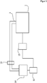
- FIG 3 an embodiment of a printing device according to the invention for parallel extrusion of printing medium is shown schematically.
- the printing device has a print head 1 according to the first exemplary embodiment described above, a print medium pump 13 arranged in the flow path of the print medium upstream of the print head, in order to convey print medium to the print head 1.
- the pressure medium pump 13 is in the present case designed as a motor-driven piston which acts on a pressure reservoir 14 in order to convey pressure medium from the pressure reservoir 14 to the pressure head 1.
- the printing device also has a control unit 15 for the pressure medium pump 13, which is designed to interact with the pressure sensor 12 of the output unit 9 of the print head 1 to regulate the pressure medium pump 13 in such a way that a constant pressure at the pressure sensor and thus directly in the flow path during the printing process of the pressure medium is applied before reaching the perforated plate 7.
- a substrate is moved below the print head 1 perpendicular to the plane of the drawing relative to the print head 1, so that a plurality of parallel lines of print medium are applied to the print head 1.
- the printing device furthermore has an input filter 16 which is arranged in the flow path of the printing medium upstream of the print head 1, in the present case between the print medium reservoir 14 and the print head 1.
- the input filter 16 has a mesh size of 200 ⁇ m, which is larger than the mesh size of the output filter.
Landscapes
- Engineering & Computer Science (AREA)
- Manufacturing & Machinery (AREA)
- Microelectronics & Electronic Packaging (AREA)
- Ink Jet (AREA)
- Push-Button Switches (AREA)
Abstract
mit einen Druckmediumeingang für das Druckmedium, welcher fluidleitend mit einer Mehrzahl von Ausgabeöffnungen des Druckkopfes verbunden ist, zur gleichzeitigen Ausgabe von Druckmedium aus den Ausgabeöffnungen und mit einem Aufweitungselement, welches im Flussweg des Druckmediums zwischen Druckmediumeingang und Ausgabeöffnungen angeordnet ist, um den Durchflussquerschnitt in Flussrichtung des Druckmediums auf ein Aspektverhältnis von zumindest 5:1 aufzuweiten. Wesentlich ist, dass der Druckkopf eine Basiseinheit mit dem Druckmediumeingang und dem Aufweitungselement und eine lösbar an der Basiseinheit angeordnete Ausgabeeinheit aufweist, dass die Ausgabeeinheit die Mehrzahl von Ausgabeöffnungen und zumindest einen Ausgabefilter für das Druckmedium aufweist, wobei im Betriebszustand bei an der Basiseinheit angeordneter Ausgabeeinheit der Ausgabefilter im Flussweg des Druckmediums zwischen Druckmediumeingang und Ausgabeöffnungen angeordnet ist. Die Erfindung betrifft weiterhin ein Verfahren zur Herstellung eines Druckkopfes.
Description
- Die Erfindung betrifft einen Druckkopf zum Parallelextrudieren von Druckmedium gemäß Anspruch 1 sowie ein Verfahren zur Herstellung eines Druckkopfes gemäß Anspruch 13.
- Bei industriellen Druckvorgängen, insbesondere bei der Herstellung von Halbleiterstrukturen, wie beispielsweise fotovoltaischen Solarzellen, ist es häufig wünschenswert, ein Druckmedium in mehreren parallelen Bahnen auf das Substrat aufzubringen. Solch ein Druckmedium kann eine Druckpaste sein, welche insbesondere einen Dotierstoff zur Dotierung eines oder mehrerer Bereiche der Halbleiterstruktur enthält, welche zur Ausbildung einer Maskierung für nachfolgende Prozessschritte dient und/oder welche Metallpartikel zum Ausbilden einer metallischen Kontaktstruktur enthält.
- Aus
DE 10 2013 223 250 A1 ist ein Druckkopf zum Aufbringen mehrerer paralleler Druckmedienlinien auf ein Substrat bekannt. - Bei vielen Anwendungen ist eine hohe Präzision der aufgebrachten Drucklinien, insbesondere eine genaue Definition des Start- und Endpunkts der Drucklinien wünschenswert. Weiterhin ist es für viele Anwendungen wünschenswert, feine Linien zu drucken, sodass die entsprechenden Auslassöffnungen des Druckkopfes einen geringen Durchmesser aufweisen.
- Solche Druckköpfe sind anfällig für Störungen aufgrund von Schmutzpartikeln, welche den Druckmediumfluss beeinträchtigen. Insbesondere ist die Auslassöffnungen solche Druckköpfe sind anfällig für ein teilweises oder vollständiges Versperren durch große Partikel wie z.B. Schmutzpartikel.
- Der vorliegenden Erfindung liegt daher die Aufgabe zugrunde, das Risiko einer Beeinträchtigung des Flussweges des Druckmediums aufgrund von Partikeln zu verringern. Gelöst ist diese Aufgabe durch einen Druckkopf zum Parallelextrudieren von Druckmedium gemäß Anspruch 1 sowie durch ein Verfahren zur Herstellung eines Druckkopfes gemäß Anspruch 13. Vorteilhafte Ausgestaltungen finden sich in den abhängigen Unteransprüchen.
- Der erfindungsgemäße Druckkopf ist bevorzugt mittels des erfindungsgemäßen Verfahrens, insbesondere einer bevorzugten Ausführungsform hiervon, hergestellt. Das erfindungsgemäße Verfahren ist bevorzugt zum Herstellen eines erfindungsgemäßen Druckkopfes, insbesondere einer vorteilhaften Ausführungsform hiervon, ausgebildet.
- Der erfindungsgemäße Druckkopf zum Parallelextrudieren von Druckmedium, insbesondere zur Herstellung von Leiterbahnen, weist einen Druckmediumeingang für das Druckmedium, welcher fluidleitend mit einer Mehrzahl von Ausgabeöffnungen des Druckkopfes verbunden ist, zur gleichzeitigen Ausgabe von Druckmedium aus den Ausgabeöffnungen auf. Weiterhin weist der Druckkopf ein Aufweitungselement auf, welches im Flussweg des Druckmediums zwischen Druckmediumeingang und Ausgabeöffnungen angeordnet ist, um den Durchflussquerschnitt in Flussrichtung des Druckmediums auf ein Aspektverhältnis von zumindest 3:1, bevorzugt zumindest 5:1, insbesondere zumindest 8:1 aufzuweiten.
- Das Aufweitungselement ermöglicht somit das Einspeisen von Druckmedium, insbesondere bei in einer geraden Linie angeordneten Ausgabeöffnungen.
- Der erfindungsgemäße Druckkopf weist weiterhin eine Basiseinheit mit dem Druckmediumeingang und dem Aufweitungselement und eine lösbar an der Basiseinheit angeordnete Ausgabeeinheit auf. Die Ausgabeeinheit weist die Mehrzahl von Ausgabeöffnungen und zumindest einen Ausgabefilter für das Druckmedium auf, wobei im Betriebszustand bei an der Basis angeordneter Ausgabeeinheit der Ausgabefilter im Flussweg des Druckmediums zwischen Druckmediumeingang und Ausgabeöffnungen angeordnet ist.
- Die Erfindung ist in der Erkenntnis begründet, dass insbesondere bei den Ausgabeöffnungen ein hohes Risiko besteht, dass diese durch Partikel, insbesondere durch Fremdpartikel zugesetzt werden und somit kein oder zumindest ein verringerter Durchfluss von Druckmedium erfolgt. Die Erfahrungen des Anmelders zeigen weiterhin, dass bei Einbau und Wartung des Druckkopfes häufig die Anforderungen an eine saubere, von Schmutzpartikeln freie Umgebung nicht eingehalten werden und somit insbesondere bei Austausch oder Reparatur eines Druckkopfes am Ort einer Druckvorrichtung ein hohes Risiko besteht, dass Schmutzpartikel in den Druckkopf und insbesondere in den Bereich der Ausgabeöffnungen gelangen.
- Die vorliegende Erfindung vermeidet oder verringert zumindest dieses Risiko, da die lösbar an der Basiseinheit angeordnete Ausgabeeinheit einen Ausgabefilter vorweist, welcher im Betriebszustand im Flusswegs des Druckmediums zwischen Druckmediumeingang und Ausgabeöffnung angeordnet ist. Die vorliegende Erfindung eröffnet somit die Möglichkeit, den Zusammenbau der Ausgabeeinheit an einem Ort mit niedriger Schmutzkontamination durchzuführen, sodass nur ein geringes Risiko besteht, dass sich Fremdpartikel zwischen Ausgabefilter und Ausgabeöffnungen befinden. Wird nun die Ausgabeeinheit am Anwendungsort an die Basiseinheit angeordnet, so besteht kein oder zumindest ein erheblich geringeres Risiko, dass Schmutzpartikel zwischen Filter und Ausgabeöffnungen gelangen, da die Schmutzpartikel durch den Filter oder durch die Ausgabeöffnungen (im Betriebszustand entgegen dem Flussweg des Druckmediums) in die Ausgabeeinheit gelangen müssten.
- Etwaige Schmutzpartikel, welche bei Zusammenbau bzw. Wartung zwischen Basiseinheit und Ausgabeeinheit gelangen, können im Betriebszustand durch den Filter aufgehalten werden, sodass das Risiko eines Zusetzens der Ausgabeöffnungen vermieden oder zumindest erheblich verringert wird.
- In einer vorteilhaften Weiterbildung des erfindungsgemäßen Druckkopfs wird das Risiko des Zusetzens der Ausgabeöffnungen weiter verringert, indem der Ausgabefilter eine mittlere Maschengröße aufweist, welche kleiner als die Hälfte, bevorzugt kleiner als ein Viertel des mittleren Durchmessers der Ausgabeöffnungen ist.
- In einer weiteren vorteilhaften Weiterbildung ist der Filter an der Ausgabeeinheit fixiert. Hierdurch wird vermieden, dass bei Einbau- oder Wartungsarbeiten durch den Benutzer der Filter aus der Ausgabeeinheit entfernt wird und somit Schmutzpartikel in einem Bereich zwischen Filter und Ausgabeöffnungen der Ausgabeeinheit gelangen können. Die Fixierung kann durch Klemmen oder Schrauben erfolgen, insbesondere ist ein Fixierung mittels einer Fügeverbindung vorteilhaft.
- Vorteilhafterweise weist der Druckkopf einen Basisfilter auf, welcher derart an der Basiseinheit angeordnet ist, dass im Betriebszustand der Basisfilter im Flussweg des Druckmediums zwischen Druckmediumeingang und Ausgabefilter angeordnet ist. Hierdurch erfolgt eine Vorfilterung, welche insbesondere ein schnelles Zusetzen des Ausgabefilters vermeidet. Insbesondere ist es daher vorteilhaft, dass die Maschengröße des Basisfilters größer als die Maschengröße des Ausgabefilters ist.
- Der Basisfilter ist bevorzugt im aufgeweiteten Bereich des Aufweitungselementes angeordnet. Hierdurch kann der Basisfilter eine größere Querschnittsfläche aufweisen.
- In einer weiteren vorteilhaften Ausgestaltung ist die Ausgabeeinheit derart ausgebildet, dass sich der Durchflussquerschnitt in Flussrichtung des Druckmediums zwischen Ausgabefilter und Ausgabeöffnungen verringert. Zwischen Ausgabefilter und Ausgabeöffnungen ist somit bevorzugt ein Reduktionselement vorgesehen, welches den Durchflussquerschnitt in Flussrichtung ausgehend von dem Ausgabefilter verringert, bevor mit dem verringerten Durchflussquerschnitt das Druckmedium zu den Ausgabeöffnungen (die einen erheblich verringerten Durchflussquerschnitt aufweisen) gelangt.
- Der Druckkopf umfasst vorteilhafterweise einen Vorfilter, welcher an der Ausgabeeinheit angeordnet ist, derart, dass im Betriebszustand der Vorfilter im Flussweg des Druckmediums vor dem Ausgabefilter angeordnet ist. Der Vorfilter bietet eine zusätzliche Möglichkeit, Fremdpartikel zu filtern. Insbesondere weist der Ausgabefilter bevorzugt eine kleinere Maschengröße als der Vorfilter auf, sodass größere Fremdpartikel von dem Vorfilter, kleinere Fremdpartikel jedoch von dem Ausgabefilter gefiltert werden.
- Der Vorfilter ist bevorzugt zu dem Ausgabefilter beabstandet, insbesondere in Flussrichtung des Druckmediums beabstandet, bevorzugt mit einem Abstand im Bereich 0,5 mm bis 3 mm, insbesondere von 1 mm bis 2 mm. Hierdurch ergibt sich der Vorteil, dass in dem Raum zwischen Vorfilter und Ausgabefilter Fremdpartikel verbleiben können, welche zwar den Vorfilter, nicht jedoch den Ausgabefilter durchdringen. Durch das Beabstanden ist somit ein Auffangreservoir für solche Fremdpartikel gebildet.
- Der Druckkopf weist bevorzugt einen Drucksensor für das Druckmedium auf. Hierdurch ist eine Kontrolle des im Druckkopf bestehenden Drucks möglich und ist kann mittels einer Steuereinheit ein vorgegebener Druck eingestellt und erhalten werden, sodass ein einheitliches Druckbild, insbesondere eine einheitliche Druckstärke der aufgebrachten Drucklinien erzielt wird.
- Der Drucksensor ist bevorzugt im Flussweg des Druckmediums stromabwärts des Ausgabefilters angeordnet. Insbesondere ist es vorteilhaft, dass der Drucksensor im Flussweg des Druckmediums zwischen Ausgabefilter und Ausgabeöffnungen angeordnet ist. Der Druck des Druckmediums unmittelbar vor den Ausgabeöffnungen stellt einen wesentlichen Parameter dar, welcher das Druckbild, insbesondere die Dicke von aufgetragenen Druckmediumlinien beeinflusst. Daher ist es vorteilhaft, wie zuvor beschrieben, zwischen Ausgabefilter und Ausgabeöffnungen den Drucksensor anzuordnen. Die eingangs genannte Aufgabe ist weiterhin durch eine Druckvorrichtung zum Parallelextrudieren von Druckmedium gemäß Anspruch 10 gelöst, mit einem erfindungsgemäßen Drucckopf, insbesondere einem Druckkopf gemäß einer bevorzugten Ausführungsform, einer im Flussweg des Druckmediums stromaufwärts des Druckkopfes angeordneten Druckmediumpumpe, um Druckmedium aus einem Druckmediumreservoir zu dem Druckkopf zu fördern.
- Der Druckkopf der Druckvorrichtung weist bevorzugt einen Drucksensor wie zuvor beschrieben auf und die Druckvorrichtung weist weiterhin bevorzugt eine Steuereinheit für die Druckmediumpumpe auf, welche mit dem Drucksensor zusammenwirkend ausgebildet ist, um die Druckmediumpumpe derart zu regeln, dass während des Druckvorgangs ein konstanter Druck am Drucksensor besteht.
- Hierdurch werden die zuvor genannten Vorteile, insbesondere einer konstanten Druckmediumausgabe bzw. Liniendicke des ausgegebenen Druckmediums erzielt.
- In einer vorteilhaften Weiterbildung weist die Druckvorrichtung zusätzlich zu dem vorgenannten Drucksensor als ersten Drucksensor zumindest einen weiteren Drucksensor als zweiten Drucksensor auf. Der erste Drucksensor ist im Flussweg des Druckmediums nach dem Ausgabefilter und der zweite Drucksensor ist im Flussweg des Druckmediums vor dem Ausgabefilter angeordnet. Hierdurch kann durch abhängig von einer Druckdifferenz am Ort des ersten und des zweiten Drucksensors der Verschmutzungsgrad des Ausgabefilters bestimmt werden. Bevorzugt weist die Druckvorrichtung daher eine Auswerteeinheit auf, welche mit erstem und zweitem Drucksensor verbunden ist und abhängig von einer Druckdifferenz zwischen den beiden Sensoren dem Benutzer den Verschmutzungsgrad und/oder ein Austauschen des Ausgabefilters signalisiert.
- Vorteilhafterweise weist die Druckvorrichtung einen Eingangsfilter auf, welcher im Flussweg des Druckmediums vor dem Druckkopf angeordnet ist. Hierdurch können Fremdpartikel bereits am Eindringen in den Druckkopf gehindert werden. Insbesondere ist es vorteilhaft, dass der Eingangsfilter eine größere Maschengröße als der Ausgabefilter aufweist. Hierdurch ergibt sich der Vorteil, dass die Verwendungsdauer ("Standzeit") des Filters erhöht wird.
- Die eingangs genannte Aufgabe ist weiterhin durch ein Verfahren zur Herstellung eines Druckkopfes, insbesondere eines erfindungsgemäßen Druckkopfes, bevorzugt einer vorteilhaften Ausführungsform hiervon, gelöst.
- Das Verfahren dient zur Herstellung eines Druckkopfes mit einer Basiseinheit, wobei die Basiseinheit mit einem Druckmediumeingang für das Druckmedium ausgebildet wird, welcher fluidleitend mit einer Mehrzahl von Ausgabeöffnungen des Druckkopfes verbunden ist, zur gleichzeitigen Ausgabe von Druckmedium aus den Ausgabeöffnungen. Die Basiseinheit wird weiterhin mit einem Aufweitungselement ausgebildet, welches im Flussweg des Druckmediums zwischen Druckmediumeingang und Ausgabeöffnungen angeordnet ist, um den Durchflussquerschnitt in Flussrichtung des Druckmediums auf ein Aspektverhältnis von zumindest 3:1, bevorzugt zumindest 5:1, insbesondere zumindest 8:1, weiter bevorzugt zumindest 30:1 aufzuweiten.
- Wesentlich ist, dass der Druckkopf mit einer lösbar an der Basiseinheit anordenbaren Ausgabeeinheit ausgebildet wird und dass ein Ausgabefilter an der Ausgabeeinheit im Flussweg des Druckmediums vor den Ausgabeöffnungen angeordnet wird, bevorzugt mittels einer Fügeverbindung.
- Hier wird der bereits genannte Vorteil erzielt, dass aufgrund des bereits werksseitig an der Basiseinheit angeordneten Ausgabefilters dieser durch den Benutzers der Filter nicht von der Ausgabeeinheit gelöst werden muss und somit herstellerseitig ein Erzeugen der Ausgabeeinheit in einer fremdpartikelfreien oder zumindest fremdpartikelarmen Umgebung erfolgen kann und somit das Risiko, dass bei Anwendung durch den Benutzer Fremdpartikel zwischen Ausgabefilter und Ausgabeöffnungen gelangen, vermieden oder zumindest erheblich verringert wird. Dieses Risiko wird weiter verringert, indem der Ausgabefilter mittels Fügeverbindung an der Ausgabeeinheit angeordnet ist.
- Vorteilhafterweise werden die Ausgabeöffnungen mittels einem lösbaren Schutzelement, insbesondere einer Schutzfolie, verschlossen. Das lösbare Schutzelement kann von dem Benutzer unmittelbar vor Starten des Druckvorgangs gelöst werden. Hierdurch wird vermieden, dass beim Transport und Einbau oder Wartung des Ausgabeelementes Fremdpartikel durch die Ausgabeöffnungen in den Bereich zwischen Ausgabefilter und Ausgabeöffnungen gelangen.
- Vorteilhafterweise werden die Ausgabeöffnungen in einer Düsenschiene ausgebildet und die Düsenschiene mit den Ausgabeöffnungen wird mittels Fügeverbindung an der Ausgabeeinheit angeordnet.
- Hierdurch ergibt sich der Vorteil, dass eine präzise Ausgestaltung der Ausgabeöffnungen in der Düsenschiene erfolgen kann und insbesondere ein Material geeigneter Härte, insbesondere ein hochfestes Material, für die Düsenschiene verwendet werden kann. Das Anbringen der Düsenschiene mittels einer Fügeverbindung an der Ausgabeöffnung verhindert ein benutzerseitiges Abnehmen der Düsenschiene von der Ausgabeeinheit und vermeidet somit ein Eindringen von Fremdpartikeln in die Ausgabeeinheit bei abgenommener Düsenschiene.
- Der erfindungsgemäße Druckkopf wird bevorzugt zum Aufbringen paralleler Linien des Druckmediums auf ein Substrat verwendet. Hierbei ist es vorteilhaft, während des Druckvorgangs Druckkopf und Substrat relativ zueinander zu bewegen. Insbesondere zur Integration eines Inline-Prozesses ist es vorteilhaft, bei ortsfestem Druckkopf das Substrat relativ zu dem Druckkopf zu bewegen.
- Der Druckkopf ist insbesondere zur Verwendung bei der Herstellung von Halbleiterbauelementen und hierbei insbesondere bei der Herstellung von fotovoltaischen Solarzellen einsetzbar. Insbesondere ist der Druckkopf geeignet, mit Dotierstoffen und/oder mit Halbpartikeln versehenes Druckmedium auf ein Substrat auszubilden, um Dotierbereiche und/oder metallische Kontaktierungsstrukturen auszubilden.
- Ebenso liegen andere Verwendungen des Druckkopfes im Rahmen der Erfindung, insbesondere das Aufbringen anderer Druckmedien wie beispielsweise Klebstoffe, Farbe oder andere Wirkstoffe auf ein Substrat. Ebenso liegt die Verwendung des Druckkopfes zur Mikrodosierung von Druckmedium beispielsweise bei Einsatz in der Medizintechnik im Rahmen der Erfindung.
- Es liegt im Rahmen der Erfindung, mittels des erfindungsgemäßen Druckkopfes kontinuierliche Bahnen von Druckmedium zu erzeugen. Ebenso liegt es im Rahmen der Erfindung, unterbrochene Bahnen, insbesondere kurze Liniensegmente, insbesondere Linien mit punktförmigen und/oder strichartigen Segmenten zu Erzeugen.
- Weitere bevorzugte Merkmale und Ausführungsformen werden im Folgenden anhand eines Ausführungsbeispiels und den Figuren erläutert. Dabei zeigt:
- Figur 1
- ein Ausführungsbeispiel eines erfindungsgemäßen Druckkopfes in Explosionsdarstellung;
- Figur 2
- einen Querschnitt durch den Druckkopf und
- Figur 3
- ein Ausführungsbeispiel einer erfindungsgemäßen Druckvorrichtung mit dem Druckkopf gemäß den
Figuren 1 und2 . - Die Figuren zeigen schematische, nicht maßstabsgetreue Darstellungen. In den Figuren bezeichnen gleiche Bezugselemente gleiche oder gleichwirkende Elemente.
- In
Figur 1 ist ein Ausführungsbeispiel eines erfindungsgemäßen Druckkopfes 1 in perspektivischer Darstellung (Figur 1a ) sowie in Seitenansicht (Figur 1b ) dargestellt. Zur besseren Übersicht der einzelnen Komponenten ist der Druckkopf in Explosionsdarstellung gezeigt. - Der Druckkopf 1 weist einen an der Oberseite mittig liegenden Druckmediumeingang 2 auf, um dem Druckkopf 1 Druckmedium zuzuführen. Der Druckmediumeingang 2 ist fluidleitend mit einer Mehrzahl von Ausgabeöffnungen 3 verbunden.
- Aus Gründen der besseren Darstellbarkeit sind lediglich wenige Ausgabeöffnungen dargestellt. Die Ausgabeöffnungen sind entlang einer geraden Linie angeordnet und weisen vorliegend jeweils eine kreisförmige Öffnung mit einem Durchmesser im Bereich von 5µm bis 500µm, vorliegend 25 µm und einem Abstand im Bereich 0,5mm bis 5mm, vorliegend 1,2mm auf. Bei diesem Ausführungsbeispiel sind 130 Ausgabeöffnungen vorgesehen, die jedoch - wie zuvor beschrieben - aus Gründen der Darstellbarkeit nicht vollzählig gezeigt sind. Exemplarisch sind die randständigen Ausgabeöffnungen mit dem Bezugszeichen 3 versehen. Das vorliegende Ausführungsbeispiel ist für die Verwendung mit Silberpaste zum Erzeugen von metallischen Kontaktierungsstrukturen einer photovoltaischen Solarzelle geeignet. Bei Verwendung anderer Druckmedien können andere Dimensionierungen, insbesondere der Geometrie des Druckkopfes, der Ausgabeöffnungen, ebenso der Maschengrößen der Filter vorteilhaft sein.
- Der Druckkopf weist eine Basiseinheit 8 mit dem Druckmediumeingang 2 und eine Ausgabeeinheit 9 mit einem Lochplatte 7 auf, in welcher die Ausgabeöffnungen 3 ausgebildet sind.
- In
Figur 2 ist eine Schnittdarstellung eines mittigen Schnitts durch den Drucckopf, sodass die Schnittebene somit parallel zur Zeichenebene gemäß der Darstellung inFigur 1b liegt und die gestrichelten Linien A gemäß der DarstellungFigur 1a enthält. - Wie in
Figur 2 ersichtlich, weist die Basiseinheit 8 ein Aufweitungselement 10 auf. In Flussrichtung D des Druckmediums verbreitert sich der Durchflussquerschnitt durch das Aufweitungselement, sodass am unteren Ende E der Basiseinheit 8 ein Durchflussquerschnitt mit einer Länge L parallel zur Zeichenebene gemäßFigur 2 von vorliegend 160 mm und einer Breite B senkrecht zur Zeichenebene inFigur 2 von vorliegend 4 mm und somit ein Aspektverhältnis von 40:1 vorliegt. - Der Durchflussquerschnitt ist somit in Flussrichtung des Druckmediums auf ein Aspektverhältnis größer 5:1 durch das Aufweitungselement aufgeweitet.
- Die Ausgabeeinheit 9 ist lösbar an der Basiseinheit 8 angeordnet, vorliegend mittels nicht dargestellter Schrauben, welche in Gewindebohrungen in den Fortsätzen F (in den
Figuren 1a und 1b ersichtlich) eingreifen. - Die Ausgabeeinheit 9 weist die Lochplatte 7 mit der Mehrzahl von Ausgabeöffnungen und dem Ausgabefilter 4 auf, welcher mittels Fügeverbindung innerhalb der Ausgabeeinheit 9 angeordnet ist. Bei an der Basiseinheit 8 angeordneter Ausgabeeinheit liegt der Ausgabefilter somit im Flussweg des Druckmediums zwischen Druckmediumeingang 2 und den Ausgabeöffnungen 3.
- Mittels des Ausgabefilters 4, welcher vorliegend eine Maschengröße von 5 µm aufweist, kann somit das Eindringen von Partikeln größer dieser Maschengröße in dem Bereich zwischen Ausgabefilter 4 und Lochplatte 7 der Ausgabeeinheit 9 vermieden werden und somit das Risiko, dass die Ausgabeöffnungen 3 während des Druckvorgangs durch Partikel verschlossen werden, erheblich verringert werden.
- Weiterhin wird herstellerseitig in einer schmutzfreien Umgebung die Lochplatte 7 und auch der Ausgabefilter 4 mittels Fügeverbindung an der Ausgabeeinheit 9 angeordnet. Hierdurch ist gewährleistet, dass durch den Benutzer kein Öffnen des Bereichs zwischen Lochplatte 7 und Ausgabefilter 4 erfolgt und somit das Eindringen größerer Schmutzpartikel in diesem Bereich vermieden oder zumindest ein solches Risiko erheblich verringert wird. Ebenso ist in einer alternativen Ausbildung eine Anordnung mittels Klemmen oder Schrauben möglich.
- Sollte im Rahmen von Wartungsarbeiten dennoch ein Austausch des Ausgabefilters 4 oder der Lochplatte 7 notwendig sein, so kann der Benutzer in einfacher Weise die Ausgabeeinheit 9 von der Basiseinheit 8 lösen und lediglich die Ausgabeeinheit austauschen.
- Der Druckkopf 1 weist weiterhin einen Basisfilter 6 auf. Dieser ist, wie in
Figur 2 ersichtlich, innerhalb der Basiseinheit 8 angeordnet, sodass im Betriebszustand, bei an der Basiseinheit 8 angeordneter Ausgabeeinheit 9 der Basisfilter im Flussweg des Druckmediums zwischen Druckmediumeingang 2 und Ausgabefilter 4 angeordnet ist. Die Maschengröße des Basisfilters ist größer als die Maschengröße des Ausgabefilters, vorliegend werden etwa 5 µm verwendet. - Wie in
Figur 2 ersichtlich, ist der Basisfilter 6 im aufgeweiteten Bereich des Aufweitungselementes 10 angeordnet. - Die Ausgabeeinheit 9 weist seitliche Schrägen S auf, sodass sich der Durchflussquerschnitt in Flussrichtung des Druckmediums zwischen Ausgabefilter 4 und Lochplatte 7 verringert. Hierdurch ergibt sich der Vorteil, dass die Filterfläche maximal ist und gleichzeitig eine gute Montierbarkeit sichergestellt wird.
- Der Druckkopf 1 weist weiterhin einen Vorfilter 5 auf. Dieser ist ebenfalls mittels Fügeverbindung am oberen Ende an der Ausgabeeinheit 9 angeordnet, sodass im Betriebszustand der Vorfilter 5 im Flussweg des Druckmediums vor dem Ausgabefilter 4 angeordnet ist.
- Der Vorfilter weist vorliegend eine größere Maschengröße als der Ausgabefilter auf, nämlich 10µm. Hierdurch ergibt sich der Vorteil, dass sowohl der Druckverlust, als auch die Wahrscheinlichkeit einer Zusetzung am Ausgabefilter minimiert wird.
- Der Vorfilter 5 ist beabstandet zu dem Ausgabefilter 4 angeordnet, sodass sich ein Expansionsraum 11 in der Ausgabeeinheit 9 zwischen Vorfilter 5 und Ausgabefilter 4 ergibt. Dies weist den Vorteil auf, dass ein lateraler Druckausgleich in der Paste stattfinden kann, was insb. bei Teilzusetzung einzelner Maschen wichtig ist.
- In Flussrichtung des Druckmediums beträgt der Abstand des Vorfilters 5 zu dem Ausgabefilter 4 vorliegend 1mm.
- Der Druckkopf 1 weist weiterhin einen Drucksensor 12 als ersten Drucksensor auf, welcher an einer der Schrägen der Ausgabeeinheit 9 und somit im Bereich zwischen Ausgabefilter 4 und Lochplatte 7 angeordnet ist.
- Mittels des Drucksensors 12 kann somit der Druck des Druckmediums unmittelbar vor Ausgabe des Druckmediums durch die Ausgabeöffnungen 3 gemessen werden. Weiterhin weist der Druckkopf 1 einen zweiten Drucksensor 12' auf, welcher in Flussrichtung des Druckmediums vor dem Ausgabefilter 4 angeordnet ist. Über eine Druckdifferenz zwischen zweitem Sensor 12' und erstem Sensor 12 wird der Verschmutzungsgrad des Ausgabefilters 4 mittels einer Auswerteeinheit ermittelt.
- In
Figur 3 ist ein Ausführungsbeispiel einer erfindungsgemäßen Druckvorrichtung zum Parallelextrudieren von Druckmedium schematisch dargestellt. Die Druckvorrichtung weist einen Druckkopf 1 gemäß dem zuvor beschriebenen ersten Ausführungsbeispiel auf, eine im Flussweg des Druckmediums stromaufwärts des Druckkopfes angeordnete Druckmediumpumpe 13, um Druckmedium zu dem Druckkopf 1 zu fördern. Die Druckmediumpumpe 13 ist vorliegend als mit einem motorisch betriebenen Kolben ausgebildet, welcher auf ein Druckreservoir 14 einwirkt, um Druckmedium aus dem Druckreservoir 14 zu dem Drucckopf 1 zu fördern. - Die Druckvorrichtung weist weiterhin eine Steuereinheit 15 für die Druckmediumpumpe 13 auf, welche mit dem Drucksensor 12 der Ausgabeeinheit 9 des Druckkopfes 1 zusammenwirkend ausgebildet ist, um die Druckmediumpumpe 13 derart zu regeln, dass während des Druckvorgangs ein konstanter Druck am Drucksensor und somit unmittelbar im Flussweg des Druckmediums vor Erreichen der Lochplatte 7 anliegt.
- Hierdurch kann ein Druck mit einer konstanten Linienbreite und Linienhöhe gewährleistet werden.
- Für einen Druckvorgang wird ein Substrat unterhalb des Druckkopfes 1 senkrecht zur Zeichenebene relativ zu dem Druckkopf 1 bewegt, sodass auf dem Druckkopf 1 mehrere parallele Druckmediumlinien aufgebracht werden.
- Die Druckvorrichtung weist weiterhin einen Eingangsfilter 16 auf, welcher im Flussweg des Druckmediums vor dem Druckkopf 1, vorliegend zwischen Druckmediumreservoir 14 und Druckkopf 1 angeordnet ist. Hierdurch ergibt sich der Vorteil, dassdie Pumpe direkt auf das Medium wirken kann. Der Eingangsfilter 16 weist vorliegend eine Maschengröße von 200µm auf, welche größer als die Maschengröße des Ausgabefilters ist.
-
- 1
- Druckkopf
- 2
- Druckmediumeingang
- 3
- Ausgabeöffnung
- 4
- Ausgabefilter
- 5
- Vorfilter
- 6
- Basisfilter
- 7
- Lochplatte
- 8
- Basiseinheit
- 9
- Ausgabeeinheit
- 10
- Aufweitungselement
- 11
- Expansionsraum
- 12
- Drucksensor
- 13
- Druckmediumpumpe
- 14
- Druckmediumreservoir
- 15
- Steuereinheit
- 16
- Eingangsfilter
Claims (15)
- Druckkopf (1) zum Parallelextrudieren von Druckmedium, insbesondere zur Herstellung von Leiterbahnen,
mit einen Druckmediumeingang für das Druckmedium, welcher fluidleitend mit einer Mehrzahl von Ausgabeöffnungen des Druckkopfes verbunden ist, zur gleichzeitigen Ausgabe von Druckmedium aus den Ausgabeöffnungen und mit einem Aufweitungselement, welches im Flussweg des Druckmediums zwischen Druckmediumeingang (2) und Ausgabeöffnungen angeordnet ist, um den Durchflussquerschnitt in Flussrichtung des Druckmediums auf ein Aspektverhältnis von zumindest 3:1 aufzuweiten, dadurch gekennzeichnet,
dass der Druckkopf (1) eine Basiseinheit (8) mit dem Druckmediumeingang (2) und dem Aufweitungselement (10) und eine lösbar an der Basiseinheit (8) angeordnete Ausgabeeinheit (9) aufweist,
dass die Ausgabeeinheit (9) die Mehrzahl von Ausgabeöffnungen und zumindest einen Ausgabefilter (4) für das Druckmedium aufweist, wobei im Betriebszustand bei an der Basiseinheit (8) angeordneter Ausgabeeinheit (9) der Ausgabefilter (4) im Flussweg des Druckmediums zwischen Druckmediumeingang (2) und Ausgabeöffnungen angeordnet ist. - Druckkopf (1) nach Anspruch 1,
dadurch gekennzeichnet,
dass der Ausgabefilter (4) eine mittlere Maschengröße aufweist, welche kleiner als die Hälfte, bevorzugt kleiner als ein Viertel des mittleren Durchmessers der Ausgabeöffnungen ist. - Druckkopf (1) nach einem der vorangegangenen Ansprüche,
dadurch gekennzeichnet,
dass der Ausgabefilter (4) an der Ausgabeeinheit (9) fixiert ist, insbesondere mittels Fügeverbindung. - Druckkopf (1) nach eine der vorangegangenen Ansprüche,
dadurch gekennzeichnet,
dass der Druckkopf (1) einen Basisfilter (6) aufweist, welcher derart an Basiseinheit (8) angeordnet ist, dass im Betriebszustand der Basisfilter (6) im Flussweg des Druckmediums zwischen Druckmediumeingang (2) und Ausgabefilter (4) angeordnet ist,
insbesondere,
dass die Maschengröße des Basisfilters größer als die Maschengröße des Ausgabefilters ist. - Druckkopf (1) nach Anspruch 4,
dadurch gekennzeichnet,
dass der Basisfilter (6) bevorzugt im aufgeweiteten Bereich des Aufweitungselementes angeordnet ist, - Druckkopf (1) nach einem der vorangegangenen Ansprüche,
dadurch gekennzeichnet,
dass die Ausgabeeinheit (9) derart ausgebildet ist, dass sich der Durchflussquerschnitt in Flussrichtung des Druckmediums zwischen Ausgabefilter (4) und Ausgabeöffnungen verringert. - Druckkopf (1) nach einem der vorangegangenen Ansprüche,
dadurch gekennzeichnet,
dass der Druckkopf (1) einen Vorfilter (5) umfasst, welcher an der Ausgabeeinheit (9) angeordnet ist, derart, dass im Betriebszustand der Vorfilter (5) im Flussweg des Druckmediums vor dem Ausgabefilter (4) angeordnet ist,
insbesondere,
dass der Ausgabefilter (4) eine kleinere Maschengröße als der Vorfilter (5) aufweist. - Druckkopf (1) nach Anspruch 7,
dadurch gekennzeichnet,
dass der Vorfilter (5) zum Ausgabefilter (4) beabstandet ist, insbesondere in Flussrichtung des Druckmediums beabstandet ist, bevorzugt mit einem Abstand im Bereich 0,25mm bis 3mm, insbesondere 0,5mm bis 1mm. - Druckkopf (1) nach einem der vorangegangenen Ansprüche,
dadurch gekennzeichnet,
dass der Druckkopf (1) einen Drucksensor (12) für das Druckmedium aufweist, welcher im Flussweg des Druckmediums stromabwärts des Ausgabefilters angeordnet ist, insbesondere zwischen Ausgabefilter (4) und Ausgabeöffnungen. - Druckvorrichtung zum Parallelextrudieren von Druckmedium,
mit einem Druckkopf (1) nach einem der vorangegangenen Ansprüche, einer im Flussweg des Druckmediums stromaufwärts des Druckkopfes angeordneten Druckmediumpumpe (13), um Druckmedium aus einem Druckmediumreservoir (14) zu dem Druckkopf (1) zu fördern. - Druckvorrichtung nach Anspruch 10,
dadurch gekennzeichnet,
dass der Druckkopf (1) einen Drucksensor (12) gemäß Anspruch 9 aufweist,
dass die Druckvorrichtung eine Steuereinheit (15) für die Druckmediumpumpe (13) aufweist, welche mit dem Drucksensor (12) zusammenwirkend ausgebildet ist, um die Druckmediumpumpe (13) abhängig von den Daten des Drucksensors (12) zu regeln. - Druckvorrichtung nach einem der vorangegangenen Ansprüche,
dadurch gekennzeichnet,
dass die Druckvorrichtung einen Eingangsfilter (16) aufweist, welcher im Flussweg des Druckmediums vor dem Druckkopf (1) angeordnet ist, insbesondere,
dass der Eingangsfilter (16) eine größere Maschengröße als der Ausgabefilter (4) aufweist. - Verfahren zur Herstellung eines Druckkopfes, insbesondere gemäß einem der Ansprüche 1 bis 9,
mit einer Basiseinheit (8),
wobei die Basiseinheit (8) mit einem Druckmediumeingang (2) für das Druckmedium ausgebildet wird, welcher fluidleitend mit einer Mehrzahl von Ausgabeöffnungen des Druckkopfes verbunden ist, zur gleichzeitigen Ausgabe von Druckmedium aus den Ausgabeöffnungen und die Basiseinheit (8) mit einem Aufweitungselement (10) ausgebildet wird, welches im Flussweg des Druckmediums zwischen Druckmediumeingang (2) und Ausgabeöffnungen angeordnet ist, um den Durchflussquerschnitt in Flussrichtung des Druckmediums auf ein Aspektverhältnis von zumindest 5:1 aufzuweiten,
dadurch gekennzeichnet,
dass der Druckkopf mit einer lösbar an der Basiseinheit (8) anordenbaren Ausgebeinheit ausgebildet wird,
und dass ein Ausgabefilter (4) an der Ausgabeeinheit (9) im Flussweg des Druckmediums vor den Ausgabeöffnungen fixiert wird. - Verfahren nach Anspruch 13,
dadurch gekennzeichnet,
dass die Ausgabeöffnungen mittels einem lösbaren Schutzelement, insbesondere einer Schutzfolie, verschlossen werden. - Verfahren nach einem der Ansprüche 13 bis 14,
dadurch gekennzeichnet,
dass die Ausgabeöffnungen in einer Düsenschiene ausgebildet werden und die Düsenschiene mit den Ausgabeöffnungen an der Ausgabeeinheit (9) fixiert wird, bevorzugt mittels Fügeverbindung.
Priority Applications (1)
| Application Number | Priority Date | Filing Date | Title |
|---|---|---|---|
| HRP20221535TT HRP20221535T1 (hr) | 2019-06-04 | 2020-06-02 | Glava pisača i postupak proizvodnje glave pisača |
Applications Claiming Priority (1)
| Application Number | Priority Date | Filing Date | Title |
|---|---|---|---|
| DE102019115009.4A DE102019115009A1 (de) | 2019-06-04 | 2019-06-04 | Druckkopf und Verfahren zur Herstellung eines Druckkopfs |
Publications (2)
| Publication Number | Publication Date |
|---|---|
| EP3747655A1 true EP3747655A1 (de) | 2020-12-09 |
| EP3747655B1 EP3747655B1 (de) | 2022-09-28 |
Family
ID=70975777
Family Applications (1)
| Application Number | Title | Priority Date | Filing Date |
|---|---|---|---|
| EP20177800.8A Active EP3747655B1 (de) | 2019-06-04 | 2020-06-02 | Druckkopf und verfahren zur herstellung eines druckkopfs |
Country Status (7)
| Country | Link |
|---|---|
| EP (1) | EP3747655B1 (de) |
| CN (1) | CN112026365B (de) |
| DE (1) | DE102019115009A1 (de) |
| ES (1) | ES2934638T3 (de) |
| HR (1) | HRP20221535T1 (de) |
| PL (1) | PL3747655T3 (de) |
| PT (1) | PT3747655T (de) |
Cited By (1)
| Publication number | Priority date | Publication date | Assignee | Title |
|---|---|---|---|---|
| WO2026077888A1 (de) * | 2024-10-07 | 2026-04-16 | HighLine Technology GmbH | Vorrichtung und ihre verwendung zum flächigen beschichten eines substrats |
Families Citing this family (1)
| Publication number | Priority date | Publication date | Assignee | Title |
|---|---|---|---|---|
| DE102024128846A1 (de) | 2024-10-07 | 2026-04-09 | HighLine Technology GmbH | Druckkopf und dessen Verwendung |
Citations (4)
| Publication number | Priority date | Publication date | Assignee | Title |
|---|---|---|---|---|
| US20120050428A1 (en) * | 2010-08-31 | 2012-03-01 | Rike Charles D | Liquid chamber reinforcement in contact with filter |
| EP2620286A1 (de) * | 2012-01-26 | 2013-07-31 | Nederlandse Organisatie voor toegepast -natuurwetenschappelijk onderzoek TNO | Kontinuierliches Strahldrucken eines Flüssigmaterials |
| DE102013223250A1 (de) | 2013-11-14 | 2015-05-21 | Fraunhofer-Gesellschaft zur Förderung der angewandten Forschung e.V. | Druckkopf, Druckvorrichtung und Verfahren zum Aufbringen eines Druckmediums auf ein Substrat, insbesondere eine photovoltaische Solarzelle |
| EP3456537A2 (de) * | 2017-09-13 | 2019-03-20 | Seiko Epson Corporation | Flüssigkeitsausstosskopf, flüssigkeitsausstossvorrichtung, piezoelektrische vorrichtung und verfahren zur herstellung eines flüssigkeitsausstosskopfes |
Family Cites Families (5)
| Publication number | Priority date | Publication date | Assignee | Title |
|---|---|---|---|---|
| US7837315B2 (en) * | 2005-09-05 | 2010-11-23 | Brother Kogyo Kabushiki Kaisha | Cavity unit and ink-jet recording head and apparatus |
| US20110205306A1 (en) * | 2010-02-25 | 2011-08-25 | Vaeth Kathleen M | Reinforced membrane filter for printhead |
| US20130101438A1 (en) * | 2010-06-28 | 2013-04-25 | Entegris, Inc. | Customizable dispense system with smart controller |
| DE102010044349A1 (de) * | 2010-09-03 | 2012-04-19 | Fraunhofer-Gesellschaft zur Förderung der angewandten Forschung e.V. | Verfahren und Vorrichtung zur Herstellung einer metallischen Kontaktstruktur zur elektrischen Kontaktierung einer photovoltaischen Solarzelle |
| US9707773B1 (en) * | 2016-03-15 | 2017-07-18 | inc.jet, Inc. | Apparatus for delivering ink to ink jet print heads |
-
2019
- 2019-06-04 DE DE102019115009.4A patent/DE102019115009A1/de not_active Withdrawn
-
2020
- 2020-06-02 PT PT201778008T patent/PT3747655T/pt unknown
- 2020-06-02 EP EP20177800.8A patent/EP3747655B1/de active Active
- 2020-06-02 HR HRP20221535TT patent/HRP20221535T1/hr unknown
- 2020-06-02 PL PL20177800.8T patent/PL3747655T3/pl unknown
- 2020-06-02 ES ES20177800T patent/ES2934638T3/es active Active
- 2020-06-04 CN CN202010500869.8A patent/CN112026365B/zh active Active
Patent Citations (4)
| Publication number | Priority date | Publication date | Assignee | Title |
|---|---|---|---|---|
| US20120050428A1 (en) * | 2010-08-31 | 2012-03-01 | Rike Charles D | Liquid chamber reinforcement in contact with filter |
| EP2620286A1 (de) * | 2012-01-26 | 2013-07-31 | Nederlandse Organisatie voor toegepast -natuurwetenschappelijk onderzoek TNO | Kontinuierliches Strahldrucken eines Flüssigmaterials |
| DE102013223250A1 (de) | 2013-11-14 | 2015-05-21 | Fraunhofer-Gesellschaft zur Förderung der angewandten Forschung e.V. | Druckkopf, Druckvorrichtung und Verfahren zum Aufbringen eines Druckmediums auf ein Substrat, insbesondere eine photovoltaische Solarzelle |
| EP3456537A2 (de) * | 2017-09-13 | 2019-03-20 | Seiko Epson Corporation | Flüssigkeitsausstosskopf, flüssigkeitsausstossvorrichtung, piezoelektrische vorrichtung und verfahren zur herstellung eines flüssigkeitsausstosskopfes |
Cited By (1)
| Publication number | Priority date | Publication date | Assignee | Title |
|---|---|---|---|---|
| WO2026077888A1 (de) * | 2024-10-07 | 2026-04-16 | HighLine Technology GmbH | Vorrichtung und ihre verwendung zum flächigen beschichten eines substrats |
Also Published As
| Publication number | Publication date |
|---|---|
| CN112026365A (zh) | 2020-12-04 |
| CN112026365B (zh) | 2022-08-05 |
| DE102019115009A1 (de) | 2020-12-10 |
| PT3747655T (pt) | 2022-12-27 |
| PL3747655T3 (pl) | 2023-03-20 |
| EP3747655B1 (de) | 2022-09-28 |
| HRP20221535T1 (hr) | 2023-03-03 |
| ES2934638T3 (es) | 2023-02-23 |
Similar Documents
| Publication | Publication Date | Title |
|---|---|---|
| DE3034068C2 (de) | Extrusionswerkzeug für die Herstellung von honigwaben-ähnlichen Profilen, insbesondere als Katalysatorträger, sowie Verfahren zu dessen Herstellung | |
| EP4234094B1 (de) | Auftragsdüse | |
| EP0705649A1 (de) | Verfahren zur Herstellung eines Flach- oder Zentripetalsiebes | |
| DE3602941C1 (de) | Duese,insbesondere Zerstaeubungsduese fuer OElbrenner | |
| DE102010038583A1 (de) | Düsenanordnung zum Abgeben von flüssigem Material | |
| EP3747655B1 (de) | Druckkopf und verfahren zur herstellung eines druckkopfs | |
| DE60016463T2 (de) | Fluidregelventil und platte mit einem filter | |
| DE19804493A1 (de) | Filtermedium für die Fest/Flüssig-Trennung | |
| DE102015226754A1 (de) | Filtereinrichtung | |
| EP0810019B1 (de) | Spaltfilterkerze für die Anschwemmfiltration, Verfahren zu deren Herstellung und Endstück für eine Spaltfilterkerze für die Anschwemmfiltration | |
| AT524317B1 (de) | Abstreifleiste und Bausatz zur Verwendung in einer Anlage zur Erzeugung einer Papierbahn | |
| DE102021004243B4 (de) | Ventil und Verwendung eines Ventils | |
| DE102016114040A1 (de) | Strömungsmodul und Verfahren zur Herstellung eines Strömungsmoduls für einen Stoffauflauf einer Papiermaschine | |
| DE4207951C2 (de) | Kapazitiver Druck- oder Differenzdrucksensor in Glas-Silizium-Technik | |
| EP3688220A1 (de) | Verfahren und vorrichtung zur herstellung eines strömungselements | |
| DE202013003829U1 (de) | Filtervorrichtung zum Filtern von Fluid | |
| EP0233980A1 (de) | Membranfilterplatte für eine Filterpresse oder dergleichen mit Stütznocken | |
| DE2432181B2 (de) | Dichtungsanordnung | |
| DE2653875B2 (de) | Vorrichtung für die Ultrafiltration | |
| DE102010038814A1 (de) | Metallstruktur einer Rückenlehne eines Kraftfahrzeugsitzes | |
| EP1529579B1 (de) | Stangenartiges Verzahnungswerkzeug | |
| DE102016015752A1 (de) | Strömunqsqitter und Verfahren zur Herstellunq eines Strömunqsqitters für einen Stoffauflauf einer Papiermaschine | |
| DE69100898T2 (de) | Stanzstempelhalteblock und montageverfahren der stempel im genannten block. | |
| AT399104B (de) | Filter, insbesondere rückspülbares filter, für die reinigung verunreinigten thermoplastischen kunststoffgutes | |
| DE1475543C (de) | Verfahren zur Herstellung einer Siebplatte für eine Zumeßeinheit einer Zentralschmierung |
Legal Events
| Date | Code | Title | Description |
|---|---|---|---|
| REG | Reference to a national code |
Ref country code: HR Ref legal event code: TUEP Ref document number: P20221535T Country of ref document: HR |
|
| PUAI | Public reference made under article 153(3) epc to a published international application that has entered the european phase |
Free format text: ORIGINAL CODE: 0009012 |
|
| STAA | Information on the status of an ep patent application or granted ep patent |
Free format text: STATUS: THE APPLICATION HAS BEEN PUBLISHED |
|
| AK | Designated contracting states |
Kind code of ref document: A1 Designated state(s): AL AT BE BG CH CY CZ DE DK EE ES FI FR GB GR HR HU IE IS IT LI LT LU LV MC MK MT NL NO PL PT RO RS SE SI SK SM TR |
|
| AX | Request for extension of the european patent |
Extension state: BA ME |
|
| STAA | Information on the status of an ep patent application or granted ep patent |
Free format text: STATUS: REQUEST FOR EXAMINATION WAS MADE |
|
| 17P | Request for examination filed |
Effective date: 20210526 |
|
| RBV | Designated contracting states (corrected) |
Designated state(s): AL AT BE BG CH CY CZ DE DK EE ES FI FR GB GR HR HU IE IS IT LI LT LU LV MC MK MT NL NO PL PT RO RS SE SI SK SM TR |
|
| RAP3 | Party data changed (applicant data changed or rights of an application transferred) |
Owner name: FRAUNHOFER-GESELLSCHAFT ZUR FOERDERUNG DER ANGEWANDTEN FORSCHUNG E.V. |
|
| GRAP | Despatch of communication of intention to grant a patent |
Free format text: ORIGINAL CODE: EPIDOSNIGR1 |
|
| STAA | Information on the status of an ep patent application or granted ep patent |
Free format text: STATUS: GRANT OF PATENT IS INTENDED |
|
| RIC1 | Information provided on ipc code assigned before grant |
Ipc: H05K 3/12 20060101ALI20220411BHEP Ipc: H01L 31/18 20060101ALI20220411BHEP Ipc: B41J 2/005 20060101ALI20220411BHEP Ipc: B41J 2/03 20060101AFI20220411BHEP |
|
| INTG | Intention to grant announced |
Effective date: 20220504 |
|
| GRAS | Grant fee paid |
Free format text: ORIGINAL CODE: EPIDOSNIGR3 |
|
| GRAA | (expected) grant |
Free format text: ORIGINAL CODE: 0009210 |
|
| STAA | Information on the status of an ep patent application or granted ep patent |
Free format text: STATUS: THE PATENT HAS BEEN GRANTED |
|
| AK | Designated contracting states |
Kind code of ref document: B1 Designated state(s): AL AT BE BG CH CY CZ DE DK EE ES FI FR GB GR HR HU IE IS IT LI LT LU LV MC MK MT NL NO PL PT RO RS SE SI SK SM TR |
|
| REG | Reference to a national code |
Ref country code: GB Ref legal event code: FG4D Free format text: NOT ENGLISH |
|
| REG | Reference to a national code |
Ref country code: CH Ref legal event code: EP |
|
| REG | Reference to a national code |
Ref country code: AT Ref legal event code: REF Ref document number: 1521010 Country of ref document: AT Kind code of ref document: T Effective date: 20221015 |
|
| REG | Reference to a national code |
Ref country code: DE Ref legal event code: R096 Ref document number: 502020001762 Country of ref document: DE |
|
| REG | Reference to a national code |
Ref country code: IE Ref legal event code: FG4D Free format text: LANGUAGE OF EP DOCUMENT: GERMAN |
|
| REG | Reference to a national code |
Ref country code: PT Ref legal event code: SC4A Ref document number: 3747655 Country of ref document: PT Date of ref document: 20221227 Kind code of ref document: T Free format text: AVAILABILITY OF NATIONAL TRANSLATION Effective date: 20221221 |
|
| REG | Reference to a national code |
Ref country code: NL Ref legal event code: FP |
|
| REG | Reference to a national code |
Ref country code: LT Ref legal event code: MG9D |
|
| REG | Reference to a national code |
Ref country code: SE Ref legal event code: TRGR |
|
| PG25 | Lapsed in a contracting state [announced via postgrant information from national office to epo] |
Ref country code: RS Free format text: LAPSE BECAUSE OF FAILURE TO SUBMIT A TRANSLATION OF THE DESCRIPTION OR TO PAY THE FEE WITHIN THE PRESCRIBED TIME-LIMIT Effective date: 20220928 Ref country code: NO Free format text: LAPSE BECAUSE OF FAILURE TO SUBMIT A TRANSLATION OF THE DESCRIPTION OR TO PAY THE FEE WITHIN THE PRESCRIBED TIME-LIMIT Effective date: 20221228 Ref country code: LV Free format text: LAPSE BECAUSE OF FAILURE TO SUBMIT A TRANSLATION OF THE DESCRIPTION OR TO PAY THE FEE WITHIN THE PRESCRIBED TIME-LIMIT Effective date: 20220928 Ref country code: LT Free format text: LAPSE BECAUSE OF FAILURE TO SUBMIT A TRANSLATION OF THE DESCRIPTION OR TO PAY THE FEE WITHIN THE PRESCRIBED TIME-LIMIT Effective date: 20220928 Ref country code: FI Free format text: LAPSE BECAUSE OF FAILURE TO SUBMIT A TRANSLATION OF THE DESCRIPTION OR TO PAY THE FEE WITHIN THE PRESCRIBED TIME-LIMIT Effective date: 20220928 |
|
| REG | Reference to a national code |
Ref country code: ES Ref legal event code: FG2A Ref document number: 2934638 Country of ref document: ES Kind code of ref document: T3 Effective date: 20230223 |
|
| PG25 | Lapsed in a contracting state [announced via postgrant information from national office to epo] |
Ref country code: GR Free format text: LAPSE BECAUSE OF FAILURE TO SUBMIT A TRANSLATION OF THE DESCRIPTION OR TO PAY THE FEE WITHIN THE PRESCRIBED TIME-LIMIT Effective date: 20221229 |
|
| REG | Reference to a national code |
Ref country code: HR Ref legal event code: T1PR Ref document number: P20221535 Country of ref document: HR |
|
| PG25 | Lapsed in a contracting state [announced via postgrant information from national office to epo] |
Ref country code: SM Free format text: LAPSE BECAUSE OF FAILURE TO SUBMIT A TRANSLATION OF THE DESCRIPTION OR TO PAY THE FEE WITHIN THE PRESCRIBED TIME-LIMIT Effective date: 20220928 Ref country code: RO Free format text: LAPSE BECAUSE OF FAILURE TO SUBMIT A TRANSLATION OF THE DESCRIPTION OR TO PAY THE FEE WITHIN THE PRESCRIBED TIME-LIMIT Effective date: 20220928 |
|
| PG25 | Lapsed in a contracting state [announced via postgrant information from national office to epo] |
Ref country code: SK Free format text: LAPSE BECAUSE OF FAILURE TO SUBMIT A TRANSLATION OF THE DESCRIPTION OR TO PAY THE FEE WITHIN THE PRESCRIBED TIME-LIMIT Effective date: 20220928 Ref country code: IS Free format text: LAPSE BECAUSE OF FAILURE TO SUBMIT A TRANSLATION OF THE DESCRIPTION OR TO PAY THE FEE WITHIN THE PRESCRIBED TIME-LIMIT Effective date: 20230128 Ref country code: EE Free format text: LAPSE BECAUSE OF FAILURE TO SUBMIT A TRANSLATION OF THE DESCRIPTION OR TO PAY THE FEE WITHIN THE PRESCRIBED TIME-LIMIT Effective date: 20220928 |
|
| REG | Reference to a national code |
Ref country code: HR Ref legal event code: ODRP Ref document number: P20221535 Country of ref document: HR Payment date: 20230519 Year of fee payment: 4 |
|
| P01 | Opt-out of the competence of the unified patent court (upc) registered |
Effective date: 20230524 |
|
| REG | Reference to a national code |
Ref country code: DE Ref legal event code: R097 Ref document number: 502020001762 Country of ref document: DE |
|
| PG25 | Lapsed in a contracting state [announced via postgrant information from national office to epo] |
Ref country code: AL Free format text: LAPSE BECAUSE OF FAILURE TO SUBMIT A TRANSLATION OF THE DESCRIPTION OR TO PAY THE FEE WITHIN THE PRESCRIBED TIME-LIMIT Effective date: 20220928 |
|
| PG25 | Lapsed in a contracting state [announced via postgrant information from national office to epo] |
Ref country code: DK Free format text: LAPSE BECAUSE OF FAILURE TO SUBMIT A TRANSLATION OF THE DESCRIPTION OR TO PAY THE FEE WITHIN THE PRESCRIBED TIME-LIMIT Effective date: 20220928 |
|
| PLBE | No opposition filed within time limit |
Free format text: ORIGINAL CODE: 0009261 |
|
| STAA | Information on the status of an ep patent application or granted ep patent |
Free format text: STATUS: NO OPPOSITION FILED WITHIN TIME LIMIT |
|
| 26N | No opposition filed |
Effective date: 20230629 |
|
| PG25 | Lapsed in a contracting state [announced via postgrant information from national office to epo] |
Ref country code: SI Free format text: LAPSE BECAUSE OF FAILURE TO SUBMIT A TRANSLATION OF THE DESCRIPTION OR TO PAY THE FEE WITHIN THE PRESCRIBED TIME-LIMIT Effective date: 20220928 |
|
| PG25 | Lapsed in a contracting state [announced via postgrant information from national office to epo] |
Ref country code: MC Free format text: LAPSE BECAUSE OF FAILURE TO SUBMIT A TRANSLATION OF THE DESCRIPTION OR TO PAY THE FEE WITHIN THE PRESCRIBED TIME-LIMIT Effective date: 20220928 |
|
| PG25 | Lapsed in a contracting state [announced via postgrant information from national office to epo] |
Ref country code: MC Free format text: LAPSE BECAUSE OF FAILURE TO SUBMIT A TRANSLATION OF THE DESCRIPTION OR TO PAY THE FEE WITHIN THE PRESCRIBED TIME-LIMIT Effective date: 20220928 |
|
| PG25 | Lapsed in a contracting state [announced via postgrant information from national office to epo] |
Ref country code: LU Free format text: LAPSE BECAUSE OF NON-PAYMENT OF DUE FEES Effective date: 20230602 |
|
| PG25 | Lapsed in a contracting state [announced via postgrant information from national office to epo] |
Ref country code: LU Free format text: LAPSE BECAUSE OF NON-PAYMENT OF DUE FEES Effective date: 20230602 |
|
| REG | Reference to a national code |
Ref country code: HR Ref legal event code: ODRP Ref document number: P20221535 Country of ref document: HR Payment date: 20240522 Year of fee payment: 5 |
|
| PG25 | Lapsed in a contracting state [announced via postgrant information from national office to epo] |
Ref country code: BG Free format text: LAPSE BECAUSE OF FAILURE TO SUBMIT A TRANSLATION OF THE DESCRIPTION OR TO PAY THE FEE WITHIN THE PRESCRIBED TIME-LIMIT Effective date: 20220928 |
|
| PG25 | Lapsed in a contracting state [announced via postgrant information from national office to epo] |
Ref country code: BG Free format text: LAPSE BECAUSE OF FAILURE TO SUBMIT A TRANSLATION OF THE DESCRIPTION OR TO PAY THE FEE WITHIN THE PRESCRIBED TIME-LIMIT Effective date: 20220928 |
|
| REG | Reference to a national code |
Ref country code: HR Ref legal event code: ODRP Ref document number: P20221535 Country of ref document: HR Payment date: 20250527 Year of fee payment: 6 |
|
| PGFP | Annual fee paid to national office [announced via postgrant information from national office to epo] |
Ref country code: DE Payment date: 20250618 Year of fee payment: 6 Ref country code: PL Payment date: 20250527 Year of fee payment: 6 |
|
| PGFP | Annual fee paid to national office [announced via postgrant information from national office to epo] |
Ref country code: GB Payment date: 20250620 Year of fee payment: 6 |
|
| PGFP | Annual fee paid to national office [announced via postgrant information from national office to epo] |
Ref country code: NL Payment date: 20250618 Year of fee payment: 6 Ref country code: BE Payment date: 20250617 Year of fee payment: 6 |
|
| PGFP | Annual fee paid to national office [announced via postgrant information from national office to epo] |
Ref country code: HR Payment date: 20250527 Year of fee payment: 6 |
|
| PGFP | Annual fee paid to national office [announced via postgrant information from national office to epo] |
Ref country code: PT Payment date: 20250523 Year of fee payment: 6 |
|
| PGFP | Annual fee paid to national office [announced via postgrant information from national office to epo] |
Ref country code: FR Payment date: 20250618 Year of fee payment: 6 |
|
| PGFP | Annual fee paid to national office [announced via postgrant information from national office to epo] |
Ref country code: AT Payment date: 20250616 Year of fee payment: 6 |
|
| PG25 | Lapsed in a contracting state [announced via postgrant information from national office to epo] |
Ref country code: CY Free format text: LAPSE BECAUSE OF FAILURE TO SUBMIT A TRANSLATION OF THE DESCRIPTION OR TO PAY THE FEE WITHIN THE PRESCRIBED TIME-LIMIT; INVALID AB INITIO Effective date: 20200602 |
|
| PGFP | Annual fee paid to national office [announced via postgrant information from national office to epo] |
Ref country code: TR Payment date: 20250528 Year of fee payment: 6 |
|
| PGFP | Annual fee paid to national office [announced via postgrant information from national office to epo] |
Ref country code: CZ Payment date: 20250520 Year of fee payment: 6 |
|
| PGFP | Annual fee paid to national office [announced via postgrant information from national office to epo] |
Ref country code: IE Payment date: 20250618 Year of fee payment: 6 |
|
| PGFP | Annual fee paid to national office [announced via postgrant information from national office to epo] |
Ref country code: SE Payment date: 20250618 Year of fee payment: 6 |
|
| PG25 | Lapsed in a contracting state [announced via postgrant information from national office to epo] |
Ref country code: HU Free format text: LAPSE BECAUSE OF FAILURE TO SUBMIT A TRANSLATION OF THE DESCRIPTION OR TO PAY THE FEE WITHIN THE PRESCRIBED TIME-LIMIT; INVALID AB INITIO Effective date: 20200602 |
|
| PGFP | Annual fee paid to national office [announced via postgrant information from national office to epo] |
Ref country code: ES Payment date: 20250718 Year of fee payment: 6 |
|
| PGFP | Annual fee paid to national office [announced via postgrant information from national office to epo] |
Ref country code: IT Payment date: 20250630 Year of fee payment: 6 |
|
| PGFP | Annual fee paid to national office [announced via postgrant information from national office to epo] |
Ref country code: CH Payment date: 20250701 Year of fee payment: 6 |