EP3746286B1 - Verfahren zur herstellung eines behälters und behälter - Google Patents
Verfahren zur herstellung eines behälters und behälter Download PDFInfo
- Publication number
- EP3746286B1 EP3746286B1 EP19703966.2A EP19703966A EP3746286B1 EP 3746286 B1 EP3746286 B1 EP 3746286B1 EP 19703966 A EP19703966 A EP 19703966A EP 3746286 B1 EP3746286 B1 EP 3746286B1
- Authority
- EP
- European Patent Office
- Prior art keywords
- compartment
- elements
- nozzle
- butt joint
- outer edge
- Prior art date
- Legal status (The legal status is an assumption and is not a legal conclusion. Google has not performed a legal analysis and makes no representation as to the accuracy of the status listed.)
- Active
Links
- 238000004519 manufacturing process Methods 0.000 title claims description 6
- 238000000034 method Methods 0.000 claims description 74
- 230000001105 regulatory effect Effects 0.000 claims description 39
- 238000003466 welding Methods 0.000 claims description 35
- 229920003023 plastic Polymers 0.000 claims description 34
- 239000004033 plastic Substances 0.000 claims description 34
- 239000000945 filler Substances 0.000 claims description 32
- 210000001503 joint Anatomy 0.000 claims description 26
- 239000012815 thermoplastic material Substances 0.000 claims description 25
- -1 polypropylene Polymers 0.000 claims description 22
- 238000005304 joining Methods 0.000 claims description 14
- 239000000463 material Substances 0.000 claims description 14
- 229920001169 thermoplastic Polymers 0.000 claims description 11
- 239000004698 Polyethylene Substances 0.000 claims description 8
- 229920000573 polyethylene Polymers 0.000 claims description 8
- 239000004416 thermosoftening plastic Substances 0.000 claims description 8
- 239000004743 Polypropylene Substances 0.000 claims description 7
- 239000004793 Polystyrene Substances 0.000 claims description 7
- 229920000139 polyethylene terephthalate Polymers 0.000 claims description 7
- 239000005020 polyethylene terephthalate Substances 0.000 claims description 7
- 229920001155 polypropylene Polymers 0.000 claims description 7
- 229920002223 polystyrene Polymers 0.000 claims description 7
- 229920000515 polycarbonate Polymers 0.000 claims description 6
- 239000004417 polycarbonate Substances 0.000 claims description 6
- 238000004113 cell culture Methods 0.000 claims description 5
- 239000006143 cell culture medium Substances 0.000 claims description 5
- 239000008187 granular material Substances 0.000 claims description 5
- 230000005855 radiation Effects 0.000 claims description 4
- 239000002184 metal Substances 0.000 description 16
- 238000010438 heat treatment Methods 0.000 description 9
- 239000000853 adhesive Substances 0.000 description 3
- 230000001070 adhesive effect Effects 0.000 description 3
- 239000007788 liquid Substances 0.000 description 2
- 239000007787 solid Substances 0.000 description 2
- VGGSQFUCUMXWEO-UHFFFAOYSA-N Ethene Chemical compound C=C VGGSQFUCUMXWEO-UHFFFAOYSA-N 0.000 description 1
- 241000238631 Hexapoda Species 0.000 description 1
- 239000004952 Polyamide Substances 0.000 description 1
- XECAHXYUAAWDEL-UHFFFAOYSA-N acrylonitrile butadiene styrene Chemical compound C=CC=C.C=CC#N.C=CC1=CC=CC=C1 XECAHXYUAAWDEL-UHFFFAOYSA-N 0.000 description 1
- 239000004676 acrylonitrile butadiene styrene Substances 0.000 description 1
- 229920000122 acrylonitrile butadiene styrene Polymers 0.000 description 1
- 239000000654 additive Substances 0.000 description 1
- 230000000996 additive effect Effects 0.000 description 1
- 230000015572 biosynthetic process Effects 0.000 description 1
- 238000001816 cooling Methods 0.000 description 1
- 238000009826 distribution Methods 0.000 description 1
- 239000003292 glue Substances 0.000 description 1
- 229920001903 high density polyethylene Polymers 0.000 description 1
- 239000004700 high-density polyethylene Substances 0.000 description 1
- 238000007654 immersion Methods 0.000 description 1
- 229920001684 low density polyethylene Polymers 0.000 description 1
- 239000004702 low-density polyethylene Substances 0.000 description 1
- 239000000155 melt Substances 0.000 description 1
- 238000002844 melting Methods 0.000 description 1
- 230000008018 melting Effects 0.000 description 1
- 238000003801 milling Methods 0.000 description 1
- 239000002245 particle Substances 0.000 description 1
- 229920002647 polyamide Polymers 0.000 description 1
- 229920000642 polymer Polymers 0.000 description 1
- 229920002635 polyurethane Polymers 0.000 description 1
- 239000004814 polyurethane Substances 0.000 description 1
- 239000002904 solvent Substances 0.000 description 1
- 238000003860 storage Methods 0.000 description 1
- 239000000126 substance Substances 0.000 description 1
- 238000002604 ultrasonography Methods 0.000 description 1
Images


Classifications
-
- B—PERFORMING OPERATIONS; TRANSPORTING
- B29—WORKING OF PLASTICS; WORKING OF SUBSTANCES IN A PLASTIC STATE IN GENERAL
- B29C—SHAPING OR JOINING OF PLASTICS; SHAPING OF MATERIAL IN A PLASTIC STATE, NOT OTHERWISE PROVIDED FOR; AFTER-TREATMENT OF THE SHAPED PRODUCTS, e.g. REPAIRING
- B29C66/00—General aspects of processes or apparatus for joining preformed parts
- B29C66/50—General aspects of joining tubular articles; General aspects of joining long products, i.e. bars or profiled elements; General aspects of joining single elements to tubular articles, hollow articles or bars; General aspects of joining several hollow-preforms to form hollow or tubular articles
- B29C66/65—General aspects of joining tubular articles; General aspects of joining long products, i.e. bars or profiled elements; General aspects of joining single elements to tubular articles, hollow articles or bars; General aspects of joining several hollow-preforms to form hollow or tubular articles with a relative motion between the article and the welding tool
-
- B—PERFORMING OPERATIONS; TRANSPORTING
- B29—WORKING OF PLASTICS; WORKING OF SUBSTANCES IN A PLASTIC STATE IN GENERAL
- B29C—SHAPING OR JOINING OF PLASTICS; SHAPING OF MATERIAL IN A PLASTIC STATE, NOT OTHERWISE PROVIDED FOR; AFTER-TREATMENT OF THE SHAPED PRODUCTS, e.g. REPAIRING
- B29C65/00—Joining or sealing of preformed parts, e.g. welding of plastics materials; Apparatus therefor
- B29C65/02—Joining or sealing of preformed parts, e.g. welding of plastics materials; Apparatus therefor by heating, with or without pressure
- B29C65/10—Joining or sealing of preformed parts, e.g. welding of plastics materials; Apparatus therefor by heating, with or without pressure using hot gases (e.g. combustion gases) or flames coming in contact with at least one of the parts to be joined
- B29C65/103—Joining or sealing of preformed parts, e.g. welding of plastics materials; Apparatus therefor by heating, with or without pressure using hot gases (e.g. combustion gases) or flames coming in contact with at least one of the parts to be joined direct heating both surfaces to be joined
-
- B—PERFORMING OPERATIONS; TRANSPORTING
- B29—WORKING OF PLASTICS; WORKING OF SUBSTANCES IN A PLASTIC STATE IN GENERAL
- B29C—SHAPING OR JOINING OF PLASTICS; SHAPING OF MATERIAL IN A PLASTIC STATE, NOT OTHERWISE PROVIDED FOR; AFTER-TREATMENT OF THE SHAPED PRODUCTS, e.g. REPAIRING
- B29C65/00—Joining or sealing of preformed parts, e.g. welding of plastics materials; Apparatus therefor
- B29C65/02—Joining or sealing of preformed parts, e.g. welding of plastics materials; Apparatus therefor by heating, with or without pressure
- B29C65/10—Joining or sealing of preformed parts, e.g. welding of plastics materials; Apparatus therefor by heating, with or without pressure using hot gases (e.g. combustion gases) or flames coming in contact with at least one of the parts to be joined
- B29C65/12—Joining or sealing of preformed parts, e.g. welding of plastics materials; Apparatus therefor by heating, with or without pressure using hot gases (e.g. combustion gases) or flames coming in contact with at least one of the parts to be joined and welding bar
-
- B—PERFORMING OPERATIONS; TRANSPORTING
- B29—WORKING OF PLASTICS; WORKING OF SUBSTANCES IN A PLASTIC STATE IN GENERAL
- B29C—SHAPING OR JOINING OF PLASTICS; SHAPING OF MATERIAL IN A PLASTIC STATE, NOT OTHERWISE PROVIDED FOR; AFTER-TREATMENT OF THE SHAPED PRODUCTS, e.g. REPAIRING
- B29C65/00—Joining or sealing of preformed parts, e.g. welding of plastics materials; Apparatus therefor
- B29C65/02—Joining or sealing of preformed parts, e.g. welding of plastics materials; Apparatus therefor by heating, with or without pressure
- B29C65/14—Joining or sealing of preformed parts, e.g. welding of plastics materials; Apparatus therefor by heating, with or without pressure using wave energy, i.e. electromagnetic radiation, or particle radiation
- B29C65/1403—Joining or sealing of preformed parts, e.g. welding of plastics materials; Apparatus therefor by heating, with or without pressure using wave energy, i.e. electromagnetic radiation, or particle radiation characterised by the type of electromagnetic or particle radiation
- B29C65/1412—Infrared [IR] radiation
-
- B—PERFORMING OPERATIONS; TRANSPORTING
- B29—WORKING OF PLASTICS; WORKING OF SUBSTANCES IN A PLASTIC STATE IN GENERAL
- B29C—SHAPING OR JOINING OF PLASTICS; SHAPING OF MATERIAL IN A PLASTIC STATE, NOT OTHERWISE PROVIDED FOR; AFTER-TREATMENT OF THE SHAPED PRODUCTS, e.g. REPAIRING
- B29C65/00—Joining or sealing of preformed parts, e.g. welding of plastics materials; Apparatus therefor
- B29C65/02—Joining or sealing of preformed parts, e.g. welding of plastics materials; Apparatus therefor by heating, with or without pressure
- B29C65/14—Joining or sealing of preformed parts, e.g. welding of plastics materials; Apparatus therefor by heating, with or without pressure using wave energy, i.e. electromagnetic radiation, or particle radiation
- B29C65/1403—Joining or sealing of preformed parts, e.g. welding of plastics materials; Apparatus therefor by heating, with or without pressure using wave energy, i.e. electromagnetic radiation, or particle radiation characterised by the type of electromagnetic or particle radiation
- B29C65/1425—Microwave radiation
-
- B—PERFORMING OPERATIONS; TRANSPORTING
- B29—WORKING OF PLASTICS; WORKING OF SUBSTANCES IN A PLASTIC STATE IN GENERAL
- B29C—SHAPING OR JOINING OF PLASTICS; SHAPING OF MATERIAL IN A PLASTIC STATE, NOT OTHERWISE PROVIDED FOR; AFTER-TREATMENT OF THE SHAPED PRODUCTS, e.g. REPAIRING
- B29C65/00—Joining or sealing of preformed parts, e.g. welding of plastics materials; Apparatus therefor
- B29C65/02—Joining or sealing of preformed parts, e.g. welding of plastics materials; Apparatus therefor by heating, with or without pressure
- B29C65/18—Joining or sealing of preformed parts, e.g. welding of plastics materials; Apparatus therefor by heating, with or without pressure using heated tools
- B29C65/20—Joining or sealing of preformed parts, e.g. welding of plastics materials; Apparatus therefor by heating, with or without pressure using heated tools with direct contact, e.g. using "mirror"
-
- B—PERFORMING OPERATIONS; TRANSPORTING
- B29—WORKING OF PLASTICS; WORKING OF SUBSTANCES IN A PLASTIC STATE IN GENERAL
- B29C—SHAPING OR JOINING OF PLASTICS; SHAPING OF MATERIAL IN A PLASTIC STATE, NOT OTHERWISE PROVIDED FOR; AFTER-TREATMENT OF THE SHAPED PRODUCTS, e.g. REPAIRING
- B29C65/00—Joining or sealing of preformed parts, e.g. welding of plastics materials; Apparatus therefor
- B29C65/02—Joining or sealing of preformed parts, e.g. welding of plastics materials; Apparatus therefor by heating, with or without pressure
- B29C65/40—Applying molten plastics, e.g. hot melt
- B29C65/42—Applying molten plastics, e.g. hot melt between pre-assembled parts
- B29C65/425—Applying molten plastics, e.g. hot melt between pre-assembled parts characterised by the composition of the molten plastics applied between pre-assembled parts
-
- B—PERFORMING OPERATIONS; TRANSPORTING
- B29—WORKING OF PLASTICS; WORKING OF SUBSTANCES IN A PLASTIC STATE IN GENERAL
- B29C—SHAPING OR JOINING OF PLASTICS; SHAPING OF MATERIAL IN A PLASTIC STATE, NOT OTHERWISE PROVIDED FOR; AFTER-TREATMENT OF THE SHAPED PRODUCTS, e.g. REPAIRING
- B29C65/00—Joining or sealing of preformed parts, e.g. welding of plastics materials; Apparatus therefor
- B29C65/48—Joining or sealing of preformed parts, e.g. welding of plastics materials; Apparatus therefor using adhesives, i.e. using supplementary joining material; solvent bonding
- B29C65/4805—Joining or sealing of preformed parts, e.g. welding of plastics materials; Apparatus therefor using adhesives, i.e. using supplementary joining material; solvent bonding characterised by the type of adhesives
- B29C65/481—Non-reactive adhesives, e.g. physically hardening adhesives
- B29C65/4815—Hot melt adhesives, e.g. thermoplastic adhesives
-
- B—PERFORMING OPERATIONS; TRANSPORTING
- B29—WORKING OF PLASTICS; WORKING OF SUBSTANCES IN A PLASTIC STATE IN GENERAL
- B29C—SHAPING OR JOINING OF PLASTICS; SHAPING OF MATERIAL IN A PLASTIC STATE, NOT OTHERWISE PROVIDED FOR; AFTER-TREATMENT OF THE SHAPED PRODUCTS, e.g. REPAIRING
- B29C65/00—Joining or sealing of preformed parts, e.g. welding of plastics materials; Apparatus therefor
- B29C65/48—Joining or sealing of preformed parts, e.g. welding of plastics materials; Apparatus therefor using adhesives, i.e. using supplementary joining material; solvent bonding
- B29C65/52—Joining or sealing of preformed parts, e.g. welding of plastics materials; Apparatus therefor using adhesives, i.e. using supplementary joining material; solvent bonding characterised by the way of applying the adhesive
- B29C65/524—Joining or sealing of preformed parts, e.g. welding of plastics materials; Apparatus therefor using adhesives, i.e. using supplementary joining material; solvent bonding characterised by the way of applying the adhesive by applying the adhesive from an outlet device in contact with, or almost in contact with, the surface of the part to be joined
-
- B—PERFORMING OPERATIONS; TRANSPORTING
- B29—WORKING OF PLASTICS; WORKING OF SUBSTANCES IN A PLASTIC STATE IN GENERAL
- B29C—SHAPING OR JOINING OF PLASTICS; SHAPING OF MATERIAL IN A PLASTIC STATE, NOT OTHERWISE PROVIDED FOR; AFTER-TREATMENT OF THE SHAPED PRODUCTS, e.g. REPAIRING
- B29C66/00—General aspects of processes or apparatus for joining preformed parts
- B29C66/01—General aspects dealing with the joint area or with the area to be joined
- B29C66/02—Preparation of the material, in the area to be joined, prior to joining or welding
- B29C66/024—Thermal pre-treatments
- B29C66/0242—Heating, or preheating, e.g. drying
-
- B—PERFORMING OPERATIONS; TRANSPORTING
- B29—WORKING OF PLASTICS; WORKING OF SUBSTANCES IN A PLASTIC STATE IN GENERAL
- B29C—SHAPING OR JOINING OF PLASTICS; SHAPING OF MATERIAL IN A PLASTIC STATE, NOT OTHERWISE PROVIDED FOR; AFTER-TREATMENT OF THE SHAPED PRODUCTS, e.g. REPAIRING
- B29C66/00—General aspects of processes or apparatus for joining preformed parts
- B29C66/01—General aspects dealing with the joint area or with the area to be joined
- B29C66/03—After-treatments in the joint area
- B29C66/034—Thermal after-treatments
-
- B—PERFORMING OPERATIONS; TRANSPORTING
- B29—WORKING OF PLASTICS; WORKING OF SUBSTANCES IN A PLASTIC STATE IN GENERAL
- B29C—SHAPING OR JOINING OF PLASTICS; SHAPING OF MATERIAL IN A PLASTIC STATE, NOT OTHERWISE PROVIDED FOR; AFTER-TREATMENT OF THE SHAPED PRODUCTS, e.g. REPAIRING
- B29C66/00—General aspects of processes or apparatus for joining preformed parts
- B29C66/01—General aspects dealing with the joint area or with the area to be joined
- B29C66/05—Particular design of joint configurations
- B29C66/10—Particular design of joint configurations particular design of the joint cross-sections
- B29C66/11—Joint cross-sections comprising a single joint-segment, i.e. one of the parts to be joined comprising a single joint-segment in the joint cross-section
- B29C66/112—Single lapped joints
-
- B—PERFORMING OPERATIONS; TRANSPORTING
- B29—WORKING OF PLASTICS; WORKING OF SUBSTANCES IN A PLASTIC STATE IN GENERAL
- B29C—SHAPING OR JOINING OF PLASTICS; SHAPING OF MATERIAL IN A PLASTIC STATE, NOT OTHERWISE PROVIDED FOR; AFTER-TREATMENT OF THE SHAPED PRODUCTS, e.g. REPAIRING
- B29C66/00—General aspects of processes or apparatus for joining preformed parts
- B29C66/01—General aspects dealing with the joint area or with the area to be joined
- B29C66/05—Particular design of joint configurations
- B29C66/10—Particular design of joint configurations particular design of the joint cross-sections
- B29C66/11—Joint cross-sections comprising a single joint-segment, i.e. one of the parts to be joined comprising a single joint-segment in the joint cross-section
- B29C66/114—Single butt joints
-
- B—PERFORMING OPERATIONS; TRANSPORTING
- B29—WORKING OF PLASTICS; WORKING OF SUBSTANCES IN A PLASTIC STATE IN GENERAL
- B29C—SHAPING OR JOINING OF PLASTICS; SHAPING OF MATERIAL IN A PLASTIC STATE, NOT OTHERWISE PROVIDED FOR; AFTER-TREATMENT OF THE SHAPED PRODUCTS, e.g. REPAIRING
- B29C66/00—General aspects of processes or apparatus for joining preformed parts
- B29C66/01—General aspects dealing with the joint area or with the area to be joined
- B29C66/05—Particular design of joint configurations
- B29C66/10—Particular design of joint configurations particular design of the joint cross-sections
- B29C66/12—Joint cross-sections combining only two joint-segments; Tongue and groove joints; Tenon and mortise joints; Stepped joint cross-sections
- B29C66/122—Joint cross-sections combining only two joint-segments, i.e. one of the parts to be joined comprising only two joint-segments in the joint cross-section
- B29C66/1222—Joint cross-sections combining only two joint-segments, i.e. one of the parts to be joined comprising only two joint-segments in the joint cross-section comprising at least a lapped joint-segment
-
- B—PERFORMING OPERATIONS; TRANSPORTING
- B29—WORKING OF PLASTICS; WORKING OF SUBSTANCES IN A PLASTIC STATE IN GENERAL
- B29C—SHAPING OR JOINING OF PLASTICS; SHAPING OF MATERIAL IN A PLASTIC STATE, NOT OTHERWISE PROVIDED FOR; AFTER-TREATMENT OF THE SHAPED PRODUCTS, e.g. REPAIRING
- B29C66/00—General aspects of processes or apparatus for joining preformed parts
- B29C66/50—General aspects of joining tubular articles; General aspects of joining long products, i.e. bars or profiled elements; General aspects of joining single elements to tubular articles, hollow articles or bars; General aspects of joining several hollow-preforms to form hollow or tubular articles
- B29C66/51—Joining tubular articles, profiled elements or bars; Joining single elements to tubular articles, hollow articles or bars; Joining several hollow-preforms to form hollow or tubular articles
- B29C66/54—Joining several hollow-preforms, e.g. half-shells, to form hollow articles, e.g. for making balls, containers; Joining several hollow-preforms, e.g. half-cylinders, to form tubular articles
- B29C66/543—Joining several hollow-preforms, e.g. half-shells, to form hollow articles, e.g. for making balls, containers; Joining several hollow-preforms, e.g. half-cylinders, to form tubular articles joining more than two hollow-preforms to form said hollow articles
-
- B—PERFORMING OPERATIONS; TRANSPORTING
- B29—WORKING OF PLASTICS; WORKING OF SUBSTANCES IN A PLASTIC STATE IN GENERAL
- B29C—SHAPING OR JOINING OF PLASTICS; SHAPING OF MATERIAL IN A PLASTIC STATE, NOT OTHERWISE PROVIDED FOR; AFTER-TREATMENT OF THE SHAPED PRODUCTS, e.g. REPAIRING
- B29C66/00—General aspects of processes or apparatus for joining preformed parts
- B29C66/50—General aspects of joining tubular articles; General aspects of joining long products, i.e. bars or profiled elements; General aspects of joining single elements to tubular articles, hollow articles or bars; General aspects of joining several hollow-preforms to form hollow or tubular articles
- B29C66/65—General aspects of joining tubular articles; General aspects of joining long products, i.e. bars or profiled elements; General aspects of joining single elements to tubular articles, hollow articles or bars; General aspects of joining several hollow-preforms to form hollow or tubular articles with a relative motion between the article and the welding tool
- B29C66/652—General aspects of joining tubular articles; General aspects of joining long products, i.e. bars or profiled elements; General aspects of joining single elements to tubular articles, hollow articles or bars; General aspects of joining several hollow-preforms to form hollow or tubular articles with a relative motion between the article and the welding tool moving the welding tool around the fixed article
-
- B—PERFORMING OPERATIONS; TRANSPORTING
- B29—WORKING OF PLASTICS; WORKING OF SUBSTANCES IN A PLASTIC STATE IN GENERAL
- B29C—SHAPING OR JOINING OF PLASTICS; SHAPING OF MATERIAL IN A PLASTIC STATE, NOT OTHERWISE PROVIDED FOR; AFTER-TREATMENT OF THE SHAPED PRODUCTS, e.g. REPAIRING
- B29C66/00—General aspects of processes or apparatus for joining preformed parts
- B29C66/70—General aspects of processes or apparatus for joining preformed parts characterised by the composition, physical properties or the structure of the material of the parts to be joined; Joining with non-plastics material
- B29C66/73—General aspects of processes or apparatus for joining preformed parts characterised by the composition, physical properties or the structure of the material of the parts to be joined; Joining with non-plastics material characterised by the intensive physical properties of the material of the parts to be joined, by the optical properties of the material of the parts to be joined, by the extensive physical properties of the parts to be joined, by the state of the material of the parts to be joined or by the material of the parts to be joined being a thermoplastic or a thermoset
- B29C66/739—General aspects of processes or apparatus for joining preformed parts characterised by the composition, physical properties or the structure of the material of the parts to be joined; Joining with non-plastics material characterised by the intensive physical properties of the material of the parts to be joined, by the optical properties of the material of the parts to be joined, by the extensive physical properties of the parts to be joined, by the state of the material of the parts to be joined or by the material of the parts to be joined being a thermoplastic or a thermoset characterised by the material of the parts to be joined being a thermoplastic or a thermoset
- B29C66/7392—General aspects of processes or apparatus for joining preformed parts characterised by the composition, physical properties or the structure of the material of the parts to be joined; Joining with non-plastics material characterised by the intensive physical properties of the material of the parts to be joined, by the optical properties of the material of the parts to be joined, by the extensive physical properties of the parts to be joined, by the state of the material of the parts to be joined or by the material of the parts to be joined being a thermoplastic or a thermoset characterised by the material of the parts to be joined being a thermoplastic or a thermoset characterised by the material of at least one of the parts being a thermoplastic
- B29C66/73921—General aspects of processes or apparatus for joining preformed parts characterised by the composition, physical properties or the structure of the material of the parts to be joined; Joining with non-plastics material characterised by the intensive physical properties of the material of the parts to be joined, by the optical properties of the material of the parts to be joined, by the extensive physical properties of the parts to be joined, by the state of the material of the parts to be joined or by the material of the parts to be joined being a thermoplastic or a thermoset characterised by the material of the parts to be joined being a thermoplastic or a thermoset characterised by the material of at least one of the parts being a thermoplastic characterised by the materials of both parts being thermoplastics
-
- B—PERFORMING OPERATIONS; TRANSPORTING
- B29—WORKING OF PLASTICS; WORKING OF SUBSTANCES IN A PLASTIC STATE IN GENERAL
- B29C—SHAPING OR JOINING OF PLASTICS; SHAPING OF MATERIAL IN A PLASTIC STATE, NOT OTHERWISE PROVIDED FOR; AFTER-TREATMENT OF THE SHAPED PRODUCTS, e.g. REPAIRING
- B29C66/00—General aspects of processes or apparatus for joining preformed parts
- B29C66/80—General aspects of machine operations or constructions and parts thereof
- B29C66/83—General aspects of machine operations or constructions and parts thereof characterised by the movement of the joining or pressing tools
- B29C66/836—Moving relative to and tangentially to the parts to be joined, e.g. transversely to the displacement of the parts to be joined, e.g. using a X-Y table
-
- B—PERFORMING OPERATIONS; TRANSPORTING
- B29—WORKING OF PLASTICS; WORKING OF SUBSTANCES IN A PLASTIC STATE IN GENERAL
- B29C—SHAPING OR JOINING OF PLASTICS; SHAPING OF MATERIAL IN A PLASTIC STATE, NOT OTHERWISE PROVIDED FOR; AFTER-TREATMENT OF THE SHAPED PRODUCTS, e.g. REPAIRING
- B29C66/00—General aspects of processes or apparatus for joining preformed parts
- B29C66/80—General aspects of machine operations or constructions and parts thereof
- B29C66/84—Specific machine types or machines suitable for specific applications
- B29C66/843—Machines for making separate joints at the same time in different planes; Machines for making separate joints at the same time mounted in parallel or in series
- B29C66/8432—Machines for making separate joints at the same time mounted in parallel or in series
-
- B—PERFORMING OPERATIONS; TRANSPORTING
- B29—WORKING OF PLASTICS; WORKING OF SUBSTANCES IN A PLASTIC STATE IN GENERAL
- B29C—SHAPING OR JOINING OF PLASTICS; SHAPING OF MATERIAL IN A PLASTIC STATE, NOT OTHERWISE PROVIDED FOR; AFTER-TREATMENT OF THE SHAPED PRODUCTS, e.g. REPAIRING
- B29C66/00—General aspects of processes or apparatus for joining preformed parts
- B29C66/90—Measuring or controlling the joining process
- B29C66/91—Measuring or controlling the joining process by measuring or controlling the temperature, the heat or the thermal flux
- B29C66/914—Measuring or controlling the joining process by measuring or controlling the temperature, the heat or the thermal flux by controlling or regulating the temperature, the heat or the thermal flux
- B29C66/9141—Measuring or controlling the joining process by measuring or controlling the temperature, the heat or the thermal flux by controlling or regulating the temperature, the heat or the thermal flux by controlling or regulating the temperature
- B29C66/91421—Measuring or controlling the joining process by measuring or controlling the temperature, the heat or the thermal flux by controlling or regulating the temperature, the heat or the thermal flux by controlling or regulating the temperature of the joining tools
-
- B—PERFORMING OPERATIONS; TRANSPORTING
- B29—WORKING OF PLASTICS; WORKING OF SUBSTANCES IN A PLASTIC STATE IN GENERAL
- B29C—SHAPING OR JOINING OF PLASTICS; SHAPING OF MATERIAL IN A PLASTIC STATE, NOT OTHERWISE PROVIDED FOR; AFTER-TREATMENT OF THE SHAPED PRODUCTS, e.g. REPAIRING
- B29C66/00—General aspects of processes or apparatus for joining preformed parts
- B29C66/90—Measuring or controlling the joining process
- B29C66/91—Measuring or controlling the joining process by measuring or controlling the temperature, the heat or the thermal flux
- B29C66/919—Measuring or controlling the joining process by measuring or controlling the temperature, the heat or the thermal flux characterised by specific temperature, heat or thermal flux values or ranges
-
- C—CHEMISTRY; METALLURGY
- C12—BIOCHEMISTRY; BEER; SPIRITS; WINE; VINEGAR; MICROBIOLOGY; ENZYMOLOGY; MUTATION OR GENETIC ENGINEERING
- C12M—APPARATUS FOR ENZYMOLOGY OR MICROBIOLOGY; APPARATUS FOR CULTURING MICROORGANISMS FOR PRODUCING BIOMASS, FOR GROWING CELLS OR FOR OBTAINING FERMENTATION OR METABOLIC PRODUCTS, i.e. BIOREACTORS OR FERMENTERS
- C12M23/00—Constructional details, e.g. recesses, hinges
- C12M23/02—Form or structure of the vessel
- C12M23/12—Well or multiwell plates
-
- C—CHEMISTRY; METALLURGY
- C12—BIOCHEMISTRY; BEER; SPIRITS; WINE; VINEGAR; MICROBIOLOGY; ENZYMOLOGY; MUTATION OR GENETIC ENGINEERING
- C12M—APPARATUS FOR ENZYMOLOGY OR MICROBIOLOGY; APPARATUS FOR CULTURING MICROORGANISMS FOR PRODUCING BIOMASS, FOR GROWING CELLS OR FOR OBTAINING FERMENTATION OR METABOLIC PRODUCTS, i.e. BIOREACTORS OR FERMENTERS
- C12M23/00—Constructional details, e.g. recesses, hinges
- C12M23/46—Means for fastening
-
- B—PERFORMING OPERATIONS; TRANSPORTING
- B29—WORKING OF PLASTICS; WORKING OF SUBSTANCES IN A PLASTIC STATE IN GENERAL
- B29C—SHAPING OR JOINING OF PLASTICS; SHAPING OF MATERIAL IN A PLASTIC STATE, NOT OTHERWISE PROVIDED FOR; AFTER-TREATMENT OF THE SHAPED PRODUCTS, e.g. REPAIRING
- B29C65/00—Joining or sealing of preformed parts, e.g. welding of plastics materials; Apparatus therefor
- B29C65/02—Joining or sealing of preformed parts, e.g. welding of plastics materials; Apparatus therefor by heating, with or without pressure
- B29C65/10—Joining or sealing of preformed parts, e.g. welding of plastics materials; Apparatus therefor by heating, with or without pressure using hot gases (e.g. combustion gases) or flames coming in contact with at least one of the parts to be joined
- B29C65/12—Joining or sealing of preformed parts, e.g. welding of plastics materials; Apparatus therefor by heating, with or without pressure using hot gases (e.g. combustion gases) or flames coming in contact with at least one of the parts to be joined and welding bar
- B29C65/125—Joining or sealing of preformed parts, e.g. welding of plastics materials; Apparatus therefor by heating, with or without pressure using hot gases (e.g. combustion gases) or flames coming in contact with at least one of the parts to be joined and welding bar characterised by the composition of the welding bar
-
- B—PERFORMING OPERATIONS; TRANSPORTING
- B29—WORKING OF PLASTICS; WORKING OF SUBSTANCES IN A PLASTIC STATE IN GENERAL
- B29C—SHAPING OR JOINING OF PLASTICS; SHAPING OF MATERIAL IN A PLASTIC STATE, NOT OTHERWISE PROVIDED FOR; AFTER-TREATMENT OF THE SHAPED PRODUCTS, e.g. REPAIRING
- B29C65/00—Joining or sealing of preformed parts, e.g. welding of plastics materials; Apparatus therefor
- B29C65/02—Joining or sealing of preformed parts, e.g. welding of plastics materials; Apparatus therefor by heating, with or without pressure
- B29C65/14—Joining or sealing of preformed parts, e.g. welding of plastics materials; Apparatus therefor by heating, with or without pressure using wave energy, i.e. electromagnetic radiation, or particle radiation
- B29C65/1429—Joining or sealing of preformed parts, e.g. welding of plastics materials; Apparatus therefor by heating, with or without pressure using wave energy, i.e. electromagnetic radiation, or particle radiation characterised by the way of heating the interface
- B29C65/1445—Joining or sealing of preformed parts, e.g. welding of plastics materials; Apparatus therefor by heating, with or without pressure using wave energy, i.e. electromagnetic radiation, or particle radiation characterised by the way of heating the interface heating both sides of the joint
-
- B—PERFORMING OPERATIONS; TRANSPORTING
- B29—WORKING OF PLASTICS; WORKING OF SUBSTANCES IN A PLASTIC STATE IN GENERAL
- B29C—SHAPING OR JOINING OF PLASTICS; SHAPING OF MATERIAL IN A PLASTIC STATE, NOT OTHERWISE PROVIDED FOR; AFTER-TREATMENT OF THE SHAPED PRODUCTS, e.g. REPAIRING
- B29C65/00—Joining or sealing of preformed parts, e.g. welding of plastics materials; Apparatus therefor
- B29C65/02—Joining or sealing of preformed parts, e.g. welding of plastics materials; Apparatus therefor by heating, with or without pressure
- B29C65/14—Joining or sealing of preformed parts, e.g. welding of plastics materials; Apparatus therefor by heating, with or without pressure using wave energy, i.e. electromagnetic radiation, or particle radiation
- B29C65/1429—Joining or sealing of preformed parts, e.g. welding of plastics materials; Apparatus therefor by heating, with or without pressure using wave energy, i.e. electromagnetic radiation, or particle radiation characterised by the way of heating the interface
- B29C65/1454—Joining or sealing of preformed parts, e.g. welding of plastics materials; Apparatus therefor by heating, with or without pressure using wave energy, i.e. electromagnetic radiation, or particle radiation characterised by the way of heating the interface scanning at least one of the parts to be joined
- B29C65/1458—Joining or sealing of preformed parts, e.g. welding of plastics materials; Apparatus therefor by heating, with or without pressure using wave energy, i.e. electromagnetic radiation, or particle radiation characterised by the way of heating the interface scanning at least one of the parts to be joined once, i.e. contour welding
-
- B—PERFORMING OPERATIONS; TRANSPORTING
- B29—WORKING OF PLASTICS; WORKING OF SUBSTANCES IN A PLASTIC STATE IN GENERAL
- B29C—SHAPING OR JOINING OF PLASTICS; SHAPING OF MATERIAL IN A PLASTIC STATE, NOT OTHERWISE PROVIDED FOR; AFTER-TREATMENT OF THE SHAPED PRODUCTS, e.g. REPAIRING
- B29C66/00—General aspects of processes or apparatus for joining preformed parts
- B29C66/01—General aspects dealing with the joint area or with the area to be joined
- B29C66/05—Particular design of joint configurations
- B29C66/10—Particular design of joint configurations particular design of the joint cross-sections
- B29C66/12—Joint cross-sections combining only two joint-segments; Tongue and groove joints; Tenon and mortise joints; Stepped joint cross-sections
- B29C66/122—Joint cross-sections combining only two joint-segments, i.e. one of the parts to be joined comprising only two joint-segments in the joint cross-section
- B29C66/1224—Joint cross-sections combining only two joint-segments, i.e. one of the parts to be joined comprising only two joint-segments in the joint cross-section comprising at least a butt joint-segment
-
- B—PERFORMING OPERATIONS; TRANSPORTING
- B29—WORKING OF PLASTICS; WORKING OF SUBSTANCES IN A PLASTIC STATE IN GENERAL
- B29C—SHAPING OR JOINING OF PLASTICS; SHAPING OF MATERIAL IN A PLASTIC STATE, NOT OTHERWISE PROVIDED FOR; AFTER-TREATMENT OF THE SHAPED PRODUCTS, e.g. REPAIRING
- B29C66/00—General aspects of processes or apparatus for joining preformed parts
- B29C66/01—General aspects dealing with the joint area or with the area to be joined
- B29C66/05—Particular design of joint configurations
- B29C66/10—Particular design of joint configurations particular design of the joint cross-sections
- B29C66/12—Joint cross-sections combining only two joint-segments; Tongue and groove joints; Tenon and mortise joints; Stepped joint cross-sections
- B29C66/122—Joint cross-sections combining only two joint-segments, i.e. one of the parts to be joined comprising only two joint-segments in the joint cross-section
- B29C66/1226—Joint cross-sections combining only two joint-segments, i.e. one of the parts to be joined comprising only two joint-segments in the joint cross-section comprising at least one bevelled joint-segment
-
- B—PERFORMING OPERATIONS; TRANSPORTING
- B29—WORKING OF PLASTICS; WORKING OF SUBSTANCES IN A PLASTIC STATE IN GENERAL
- B29C—SHAPING OR JOINING OF PLASTICS; SHAPING OF MATERIAL IN A PLASTIC STATE, NOT OTHERWISE PROVIDED FOR; AFTER-TREATMENT OF THE SHAPED PRODUCTS, e.g. REPAIRING
- B29C66/00—General aspects of processes or apparatus for joining preformed parts
- B29C66/70—General aspects of processes or apparatus for joining preformed parts characterised by the composition, physical properties or the structure of the material of the parts to be joined; Joining with non-plastics material
- B29C66/71—General aspects of processes or apparatus for joining preformed parts characterised by the composition, physical properties or the structure of the material of the parts to be joined; Joining with non-plastics material characterised by the composition of the plastics material of the parts to be joined
-
- B—PERFORMING OPERATIONS; TRANSPORTING
- B29—WORKING OF PLASTICS; WORKING OF SUBSTANCES IN A PLASTIC STATE IN GENERAL
- B29K—INDEXING SCHEME ASSOCIATED WITH SUBCLASSES B29B, B29C OR B29D, RELATING TO MOULDING MATERIALS OR TO MATERIALS FOR MOULDS, REINFORCEMENTS, FILLERS OR PREFORMED PARTS, e.g. INSERTS
- B29K2023/00—Use of polyalkenes or derivatives thereof as moulding material
- B29K2023/04—Polymers of ethylene
- B29K2023/06—PE, i.e. polyethylene
- B29K2023/0608—PE, i.e. polyethylene characterised by its density
- B29K2023/0633—LDPE, i.e. low density polyethylene
-
- B—PERFORMING OPERATIONS; TRANSPORTING
- B29—WORKING OF PLASTICS; WORKING OF SUBSTANCES IN A PLASTIC STATE IN GENERAL
- B29K—INDEXING SCHEME ASSOCIATED WITH SUBCLASSES B29B, B29C OR B29D, RELATING TO MOULDING MATERIALS OR TO MATERIALS FOR MOULDS, REINFORCEMENTS, FILLERS OR PREFORMED PARTS, e.g. INSERTS
- B29K2023/00—Use of polyalkenes or derivatives thereof as moulding material
- B29K2023/04—Polymers of ethylene
- B29K2023/06—PE, i.e. polyethylene
- B29K2023/0608—PE, i.e. polyethylene characterised by its density
- B29K2023/065—HDPE, i.e. high density polyethylene
-
- B—PERFORMING OPERATIONS; TRANSPORTING
- B29—WORKING OF PLASTICS; WORKING OF SUBSTANCES IN A PLASTIC STATE IN GENERAL
- B29K—INDEXING SCHEME ASSOCIATED WITH SUBCLASSES B29B, B29C OR B29D, RELATING TO MOULDING MATERIALS OR TO MATERIALS FOR MOULDS, REINFORCEMENTS, FILLERS OR PREFORMED PARTS, e.g. INSERTS
- B29K2023/00—Use of polyalkenes or derivatives thereof as moulding material
- B29K2023/10—Polymers of propylene
- B29K2023/12—PP, i.e. polypropylene
-
- B—PERFORMING OPERATIONS; TRANSPORTING
- B29—WORKING OF PLASTICS; WORKING OF SUBSTANCES IN A PLASTIC STATE IN GENERAL
- B29K—INDEXING SCHEME ASSOCIATED WITH SUBCLASSES B29B, B29C OR B29D, RELATING TO MOULDING MATERIALS OR TO MATERIALS FOR MOULDS, REINFORCEMENTS, FILLERS OR PREFORMED PARTS, e.g. INSERTS
- B29K2025/00—Use of polymers of vinyl-aromatic compounds or derivatives thereof as moulding material
- B29K2025/04—Polymers of styrene
- B29K2025/06—PS, i.e. polystyrene
-
- B—PERFORMING OPERATIONS; TRANSPORTING
- B29—WORKING OF PLASTICS; WORKING OF SUBSTANCES IN A PLASTIC STATE IN GENERAL
- B29K—INDEXING SCHEME ASSOCIATED WITH SUBCLASSES B29B, B29C OR B29D, RELATING TO MOULDING MATERIALS OR TO MATERIALS FOR MOULDS, REINFORCEMENTS, FILLERS OR PREFORMED PARTS, e.g. INSERTS
- B29K2055/00—Use of specific polymers obtained by polymerisation reactions only involving carbon-to-carbon unsaturated bonds, not provided for in a single one of main groups B29K2023/00 - B29K2049/00, e.g. having a vinyl group, as moulding material
- B29K2055/02—ABS polymers, i.e. acrylonitrile-butadiene-styrene polymers
-
- B—PERFORMING OPERATIONS; TRANSPORTING
- B29—WORKING OF PLASTICS; WORKING OF SUBSTANCES IN A PLASTIC STATE IN GENERAL
- B29K—INDEXING SCHEME ASSOCIATED WITH SUBCLASSES B29B, B29C OR B29D, RELATING TO MOULDING MATERIALS OR TO MATERIALS FOR MOULDS, REINFORCEMENTS, FILLERS OR PREFORMED PARTS, e.g. INSERTS
- B29K2067/00—Use of polyesters or derivatives thereof, as moulding material
- B29K2067/003—PET, i.e. poylethylene terephthalate
-
- B—PERFORMING OPERATIONS; TRANSPORTING
- B29—WORKING OF PLASTICS; WORKING OF SUBSTANCES IN A PLASTIC STATE IN GENERAL
- B29K—INDEXING SCHEME ASSOCIATED WITH SUBCLASSES B29B, B29C OR B29D, RELATING TO MOULDING MATERIALS OR TO MATERIALS FOR MOULDS, REINFORCEMENTS, FILLERS OR PREFORMED PARTS, e.g. INSERTS
- B29K2069/00—Use of PC, i.e. polycarbonates or derivatives thereof, as moulding material
-
- B—PERFORMING OPERATIONS; TRANSPORTING
- B29—WORKING OF PLASTICS; WORKING OF SUBSTANCES IN A PLASTIC STATE IN GENERAL
- B29K—INDEXING SCHEME ASSOCIATED WITH SUBCLASSES B29B, B29C OR B29D, RELATING TO MOULDING MATERIALS OR TO MATERIALS FOR MOULDS, REINFORCEMENTS, FILLERS OR PREFORMED PARTS, e.g. INSERTS
- B29K2075/00—Use of PU, i.e. polyureas or polyurethanes or derivatives thereof, as moulding material
-
- B—PERFORMING OPERATIONS; TRANSPORTING
- B29—WORKING OF PLASTICS; WORKING OF SUBSTANCES IN A PLASTIC STATE IN GENERAL
- B29K—INDEXING SCHEME ASSOCIATED WITH SUBCLASSES B29B, B29C OR B29D, RELATING TO MOULDING MATERIALS OR TO MATERIALS FOR MOULDS, REINFORCEMENTS, FILLERS OR PREFORMED PARTS, e.g. INSERTS
- B29K2077/00—Use of PA, i.e. polyamides, e.g. polyesteramides or derivatives thereof, as moulding material
-
- B—PERFORMING OPERATIONS; TRANSPORTING
- B29—WORKING OF PLASTICS; WORKING OF SUBSTANCES IN A PLASTIC STATE IN GENERAL
- B29K—INDEXING SCHEME ASSOCIATED WITH SUBCLASSES B29B, B29C OR B29D, RELATING TO MOULDING MATERIALS OR TO MATERIALS FOR MOULDS, REINFORCEMENTS, FILLERS OR PREFORMED PARTS, e.g. INSERTS
- B29K2701/00—Use of unspecified macromolecular compounds for preformed parts, e.g. for inserts
- B29K2701/12—Thermoplastic materials
-
- B—PERFORMING OPERATIONS; TRANSPORTING
- B29—WORKING OF PLASTICS; WORKING OF SUBSTANCES IN A PLASTIC STATE IN GENERAL
- B29L—INDEXING SCHEME ASSOCIATED WITH SUBCLASS B29C, RELATING TO PARTICULAR ARTICLES
- B29L2031/00—Other particular articles
- B29L2031/712—Containers; Packaging elements or accessories, Packages
Definitions
- the present invention relates to a method for producing a container made at least partially of a thermoplastic material, comprising at least one first compartment element and at least one second compartment element thermoplastically welded to the first in a connecting area, as well as a preferably produced plastic container which can be produced according to the method according to the invention.
- thermoplastic A particular challenge in the production of containers from thermoplastic is the solid, in particular residue-free, connection of several plastic elements forming the container.
- Various methods are currently used in the prior art for welding plastic parts.
- the so-called laser welding is based on the fact that two different plastics are used, one of which is transparent to the laser and the other absorbs the energy of the laser, so that the thermoplastic material is heated locally and, with the application of a joining pressure, a weld between the individual plastic parts.
- Another possibility to connect individual plastic elements is to glue the individual elements of the plastic container together, which disadvantageously, however, is the risk that residues of the adhesive or the solvent used remain at the connection point, whereby the area of use of a manufactured in this way Container is significantly restricted.
- thermoplastic plastic parts are first plasticized by heating and then connected to one another by applying a joining pressure.
- Heating element welding includes contacting at least one of the two thermoplastic plastic parts to be welded with a heating element, as a result of which the joining surface is locally plasticized.
- the plastic parts to be welded are joined by applying a joining pressure.
- the joining surface of at least one of the plastic parts to be welded is locally plasticized by means of a hot gas flow. In this process, too, the plastic parts are connected by applying a joining pressure.
- the plastic is plasticized by frictional heat that is generated when the plastic part to be welded on is rotated on a second plastic part that is locked in a non-rotating manner.
- the plastic parts to be joined melt on and are firmly joined to one another by the applied pressure.
- the DE 3609775 A1 relates to a device and the GB 848 967 A relates to a method for material-locking connection of thermoplastic material at least in the area of the connection points.
- the device comprises a heat and / or microwave beam element and a feed nozzle, via which plasticized plastic is fed in the contact area of the two plastic parts, whereby the plastic parts, which are thermoplastic at least in the area of the connection points, are materially connected to one another.
- the DE 20 2009 009762 U1 relates to a container comprising two compartment elements which can be connected to one another by means of ultrasonic welding processes, laser welding, hot stamping processes or adhesive processes.
- the DE 20 2009 009762 U1 a method comprising steps a), b) and d) of claim 1.
- the object of the present connection is to provide a method for producing a container constructed at least partially from a thermoplastic material, in which the disadvantages of the joining methods known in the prior art are overcome, so that it can advantageously be used without the need to apply a joining pressure to the adhesive, in particular - Solvent-free and particle-free welding of the individual plastic parts forming the container.
- the present invention solves the technical problem on which it is based, in particular through the subject matter of the independent claims.
- the first compartment element is a plate element.
- the second compartment element comprises a plate element and a side wall arranged around the outer circumference of the plate element, each with a distal first and proximal second outer edge arranged parallel to the plate element.
- the first and / or second compartment element comprises a side wall arranged around the outer circumference of the plate element, each with a distal first and proximal second outer edge arranged parallel to the plate element.
- the side wall of the first and / or second compartment element is preferably arranged orthogonally to the plane formed by the plate element around the outer circumference of the plate element.
- the plane formed by the plate element preferably runs parallel to the planes formed by the distal first and the proximal second outer edge.
- the distance between the plane formed by the plate element and the plane formed by the distal first outer edge is preferably greater than the distance between the plane formed by the plate element and the plane formed by the proximal second outer edge.
- the distance between the plane formed by the plate element and the plane formed by the distal first outer edge is preferably smaller than the distance between the plane formed by the plate element and the plane formed by the proximal second outer edge.
- the distance between the plane formed by the plate element and the plane formed by the distal first outer edge is preferably identical to the distance between the plane formed by the plate element and the plane formed by the proximal second outer edge.
- the side wall of a compartment element has a height of 2 to 200 mm, preferably 2 to 180 mm, preferably 2 to 160 mm, preferably 2 to 140 mm, preferably 2 to 120 mm, preferably 2 to 100 mm, preferably 2 to 80 mm, preferably 2 to 60 mm, preferably 4 to 40 mm, preferably 4 to 30 mm, preferably 4 to 25 mm, preferably 4 to 20 mm, preferably 4 to 18 mm, preferably 4 to 16 mm, preferably 6 up to 14 mm, preferably 6 to 12 mm, preferably 8 to 12 mm, preferably 10 mm.
- the height of the side wall of a compartment element is preferably at least 2 mm, preferably at least 4 mm, preferably at least 6 mm, preferably at least 8 mm, preferably at least 10 mm.
- the side walls of the individual compartment elements have different heights. All side walls of the individual compartment elements preferably have the same height.
- the side wall of a compartment element has a thickness of 0.1 to 10 mm, preferably 0.1 to 9 mm, preferably 0.2 to 8 mm, preferably 0.3 to 7 mm, preferably 0.4 up to 6 mm, preferably 0.5 to 5 mm, preferably 0.6 to 4.5 mm, preferably 0.7 to 4 mm, preferably 0.8 to 3.5 mm, preferably 1 to 3 mm, preferably 1.25 up to 2.5 mm, preferably 1.5 to 2.5 mm, preferably 1.75 to 2.25 mm, preferably 2 mm.
- the thickness of the side wall of a compartment element is preferably at least 0.1 mm, preferably at least 0.2 mm, preferably at least 0.3 mm, preferably at least 0.4 mm, preferably at least 0.5 mm, preferably at least 0.6 mm, preferably at least 0.7 mm, preferably at least 0.8 mm, preferably at least 0.9 mm, preferably at least 1 mm.
- the side walls of the individual compartment elements have different thicknesses. All side walls of the individual compartment elements preferably have the same thickness.
- the plate element of the at least two compartment elements is square, rectangular, oval or round.
- the plate element of the at least two compartment elements is preferably square.
- the plate element of the at least two compartment elements is preferably rectangular.
- the plate element of the at least two compartment elements is preferably oval.
- the plate element of the at least two compartment elements is preferably round.
- At least one further compartment element is provided in process step a), in process step b) the further compartment element with its first outer edge is fully attached to the second outer edge of the second or an optionally present further compartment element and in process step c) the between the butt joint resulting from the joined compartment elements is welded.
- each further compartment element comprises a plate element and one around the outer circumference of the plate element arranged side wall each having a distal first and proximal second outer edge arranged parallel to the plate element.
- the compartment elements are joined to one another in a rotationally secure manner.
- At least one compartment element and the welding filler are made of the same materials, preferably of the same material.
- the filler metal is plasticized by the at least one temperature-regulated nozzle.
- the filler metal is preferably plasticized in the at least one temperature-regulated nozzle.
- the temperature of the at least one temperature-regulated nozzle is 150 to 320 ° C., preferably 160 to 310 ° C., preferably 170 to 300 ° C., preferably 180 to 290 ° C., preferably 190 to 280 ° C., preferably 200 to 275 ° C, preferably 210 to 270 ° C, preferably 220 to 265 ° C, preferably 225 to 260 ° C, preferably 230 to 255 ° C, preferably 235 to 250 ° C, preferably 240 to 250 ° C.
- the temperature of the at least one temperature-regulated nozzle is preferably at least 150 ° C, preferably at least 160 ° C, preferably at least 170 ° C, preferably at least 180 ° C, preferably at least 190 ° C, preferably at least 200 ° C, preferably at least 210 ° C, preferably at least 220 ° C, preferably at least 230 ° C, preferably at least 240 ° C, preferably at least 250 ° C.
- the set temperature of the at least one temperature-regulated nozzle depends on the specific melting temperature of the at least one thermoplastic material selected in the method according to the invention and is selected so that it is plasticized by contacting the at least one temperature-regulated nozzle with the butt joint formed between the at least two compartment elements the respective first and second outer edge comes in the area of the connection zones of the compartment elements and at the same time plasticized welding filler material can be transferred to the butt joint through the at least one temperature-regulated nozzle.
- the at least one thermoplastic material is polystyrene and the temperature of the at least one temperature-regulated nozzle is 225 to 240.degree. C., preferably 230 to 235.degree.
- the at least one thermoplastic material is polyurethane and the temperature of the at least one temperature-regulated nozzle is 200 to 240.degree. C., preferably 205 to 235.degree. C., preferably 220.degree.
- the at least one thermoplastic material is polyethylene terephthalate and the temperature of the at least one temperature-regulated nozzle is 205 to 255.degree. C., preferably 210 to 250.degree. C., preferably 230.degree.
- the at least one thermoplastic material is acrylonitrile-butadiene-styrene and the temperature of the at least one temperature-regulated nozzle is 235 to 265.degree. C., preferably 240 to 260.degree. C., preferably 250.degree.
- the at least one thermoplastic material is polyamide and the temperature of the at least one temperature-regulated nozzle is 235 to 265.degree. C., preferably 240 to 260.degree. C., preferably 250.degree.
- the at least one thermoplastic material is polypropylene and the temperature of the at least one temperature-regulated nozzle is 245 to 275.degree. C., preferably 250 to 270.degree.
- the at least one thermoplastic material is polyethylene (LDPE) and the temperature of the at least one temperature-regulated nozzle is 155 to 265 ° C., preferably 160 to 260 ° C., preferably 180 to 240 ° C., preferably 200 to 220 ° C, preferably 210 ° C.
- the at least one thermoplastic material is polyethylene (HDPE) and the temperature of the at least one temperature-regulated nozzle is 255 to 305 ° C, preferably 260 to 300 ° C, preferably 280 ° C.
- the connecting zones of the at least two compartment elements consist of a material comprising one or more thermoplastics selected from the group consisting of polystyrene, polypropylene, polycarbonate, polyethylene terephthalate and polyethylene.
- At least one of the at least two compartment elements consists of a material comprising one or more thermoplastics selected from the group consisting of polystyrene, polypropylene, polycarbonate, polyethylene terephthalate and polyethylene.
- the material of the filler metal is one or more thermoplastics selected from the group consisting of polystyrene, polypropylene, polycarbonate, polyethylene terephthalate and polyethylene.
- At least one of the at least two compartment elements and the filler metal are made of the same material.
- At least one of the at least two compartment elements and the welding filler are preferably composed of one or more thermoplastics selected from the group consisting of polystyrene, polypropylene, polycarbonate, polyethylene terephthalate and polyethylene.
- the filler metal is fed to the at least one nozzle in the form of granules or a continuous strand.
- the filler metal is preferably fed to the at least one nozzle in the form of granules.
- the filler metal is preferably in the form of a continuous strand, preferably in the form of a welding wire, which is fed to the at least one nozzle.
- the compartment elements are preheated in the area of the butt joint.
- the compartment elements are preferably preheated in the region of the butt joint by hot air, infrared and / or microwave radiation.
- the weld seam is heated in a further method step c ').
- the weld seam is preferably heated by hot air, infrared and / or microwave radiation.
- the abutting of the compartment elements in method step b) forms at least one depression in the area of the butt joint between the compartment elements.
- the at least two compartment elements are welded by means of at least one temperature-regulated nozzle in process step c) in that the at least one nozzle is guided around the circumference of the butt joint in contact with the butt joint and simultaneously with plasticized welding filler the butt joint is transferred so that a weld seam is formed between the two compartment elements.
- the at least two compartment elements are welded by means of at least one temperature-regulated nozzle in process step c) in that the butt joint is guided along the at least one nozzle in contact with the at least one nozzle and at the same time plasticized welding filler is transferred to the butt joint so that a weld seam is formed between the two compartment elements.
- the at least two compartment elements are preferably welded by means of at least one temperature-regulated nozzle in process step c) in that the butt joint and the at least one nozzle are moved relative to one another in contact with one another and at the same time plasticized welding filler is transferred to the butt joint, so that a weld seam between the two Compartment elements is formed.
- the at least one temperature-regulated nozzle has a diameter of 0.3 to 2 mm, preferably 0.3 to 1.8 mm, preferably 0.4 to 1.6 mm, preferably 0.4 to 1 , 4 mm, preferably 0.5 to 1.2 mm, preferably 0.5 to 1 mm, preferably 0.5 to 0.8 mm.
- the use of at least one temperature-regulated nozzle with a small nozzle diameter advantageously enables the weld seam formed between the compartment elements in step c) to have a particularly small width.
- the width of the weld seam formed between the compartment elements in step c) is preferably below 5 mm, preferably below 4.5 mm, preferably below 4 mm, preferably below 3.5 mm, preferably below 3 mm, preferably below 2.5 mm, preferably below 2 mm.
- process step c) at least three, preferably at least four, preferably at least five, preferably at least six, preferably all of the compartment elements provided in process step a) and joined together in process step b) are welded together at the same time.
- process step c) at least three, preferably at least four, preferably at least five, preferably at least six, preferably all, in process step a) are preferred compartment elements provided and joined together in process step b) are welded one after the other.
- the at least one temperature-regulated nozzle is introduced completely or partially into the at least one depression in process step c).
- the at least one temperature-regulated nozzle is preferably completely inserted into the at least one depression.
- the at least one temperature-regulated nozzle is preferably partially introduced into the at least one depression.
- the at least one temperature-regulated nozzle when completely or partially inserted into the at least one recess, contacts the two compartment elements forming the recess, in particular the two outer edges of the compartment elements forming the recess.
- thermoplastic material of the compartment elements melts in the connection area, the recess being at least partially, preferably completely, filled with the welding additive through the at least one temperature-regulated nozzle, which in particular leads to adhesive-free, solvent-free and particle-free welding the compartment elements come.
- the compartment elements are suitable for the cultivation and / or examination of cells. At least one compartment element is preferably suitable for cultivating and / or examining cells. At least one compartment element is preferably a cell culture dish.
- the plastic container obtained in step d) comprises at least two, preferably at least three, preferably at least four, preferably at least five, preferably at least six, preferably at least seven, preferably at least eight, preferably at least nine, preferably at least ten, preferably at least 20, preferably at least 30, preferably at least 40, preferably at least 50, preferably at least 100, preferably at least 200, compartment elements which are welded to one another.
- the plastic container obtained in step d) preferably comprises 2 to 20, preferably 2 to 18, preferably 2 to 16, preferably 2 to 14, preferably 2 to 12, preferably 2 to 10, preferably 4 to 10, preferably 4 to 8, preferably 4 to 6, compartment elements that are welded together.
- the at least one compartment element has a connecting, preferably central, channel.
- the at least one compartment element preferably has a connecting, preferably central, channel as a supply channel for cell culture medium.
- Each of the compartment elements preferably has a connecting, preferably central, channel.
- Each of the compartment elements preferably has a connecting, preferably central, channel as a supply channel for cell culture medium.
- At least one compartment element has a disposal channel. At least one compartment element preferably has a disposal channel for used cell culture medium.
- an exchange of substances preferably gas and / or liquid exchange, is possible between individual compartment elements.
- a material exchange preferably gas and / or liquid exchange, is preferably possible between all compartment elements.
- At least one, preferably exactly one, compartment element has at least one closable, preferably reclosable, opening.
- the at least one opening has a thread, preferably an external thread.
- the container which is at least partially made of thermoplastic material, can preferably be filled and emptied via the at least one opening.
- the present invention also relates to a plastic container comprising at least two compartment elements which can be produced, preferably produced, according to the method according to the invention.
- the plastic container comprising at least two compartment elements is a cell culture vessel.
- the plastic container comprising at least two compartment elements is preferably a cell culture vessel which is constructed from at least one cell culture dish.
- a “side wall” is understood to mean a wall of a compartment element which encloses an open or closed cavity.
- the respective side walls of the at least two compartment elements can form the side wall of the plastic container according to the invention.
- the side wall of a compartment element has a distal first and a proximal second outer edge, the two outer edges each lying in a plane which runs parallel to the plane formed by the plate element. If the first or second compartment element does not have a side wall, and accordingly if the first or second compartment element is a plate element, the outer edges of this first or second plate element correspond to the distal first and proximal second outer edge of a side wall.
- compartment element is understood to mean an individual structural unit of the container, which is at least partially composed of a thermoplastic material.
- the compartment element can either be a plate element or comprise a plate element and a side wall arranged around the outer circumference of the plate element. If the first compartment element is a plate element, at least the second compartment element comprises a plate element and a side wall arranged around the outer circumference of the plate element.
- plate element is understood to mean that part of a compartment element which either itself has a distal first and proximal second outer edge or has a side wall around its outer circumference, each of which comprises a distal first and proximal second outer edge arranged parallel to the plate element .
- the “distal” outer edge denotes the outer edge of the side wall arranged around the outer circumference of the plate element, which is further away from the plane formed by the plate element.
- the “proximal” outer edge is understood to mean the outer edge, which is closer to the plane formed by the plate element, of the side wall arranged around the outer circumference of the plate element.
- the "distal" outer edge is the outer edge of the plate element itself located further away from the plane formed by the plate element of the next compartment element or, if present, of the side wall arranged around the outer circumference of the plate element.
- the term “connecting zone” denotes the area of a compartment element in which at least two compartment elements are connected.
- the connection zone consists of a thermoplastic material, so that the compartment element is plasticized in this area by contacting the at least one temperature-regulated nozzle.
- the connection zones of a compartment element comprise a distal first outer edge made of thermoplastic material and a proximal second outer edge made of thermoplastic material.
- each compartment element accordingly has two connecting zones.
- the first or second compartment element is a plate element, this can also only comprise one connection zone.
- the term “and / or” is understood to mean that all members of a group which are connected by the term “and / or” are disclosed both as alternatives to one another and also cumulatively with one another in any combination.
- A, B and / or C this means that the following disclosure content is to be understood: A or B or C, or (A and B) or (A and C) or (B and C) or (A and B and C).
- the term “comprehensive” is understood to mean that in addition to the elements explicitly covered by the term, further elements that are not explicitly mentioned can also be added. In connection with the present invention, this term is also understood to mean that only the explicitly mentioned elements are covered and no further elements are present.
- the meaning of the term “comprising” is synonymous with the term “consisting of”.
- the term “comprehensive” also includes entities which, in addition to those explicitly mentioned, also contain other elements that are not mentioned, but which are of a functionally and qualitatively subordinate nature. In this embodiment, the term “comprising” is synonymous with the term “consisting essentially of”.
- FIG. 1 It shows Figure 1 the immersion of the temperature-regulated nozzle 7 into the connection zone 3 located between two compartment elements 1 and 2.
- the two compartment elements 1 and 2 are plasticized in the area of the connection zone 3.
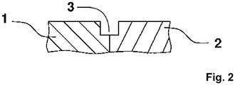
- connection zone 3 An alternative geometry for the design of the connection zone 3 is shown in FIG Figure 2 shown.
- a groove is formed between the compartment elements 1 and 2 in the area of the connecting zone 3.
- the advantage of such a groove is that plasticized filler metal can be introduced more freely between the plasticized compartment elements 1 and 2, since a cavity is created in the area directly in front of the nozzle outlet. The filler metal can be dosed into this cavity.
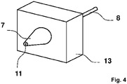
- Figure 4 shows the structure of the temperature-regulated nozzle 7.
- the nozzle tapers at the front towards the nozzle outlet 11 in order to specifically heat the connection zone 3 between two compartment elements and to place the filler metal 8 there.
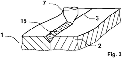
- Figure 5 shows a plastic container 9 made with the method according to the present invention and consisting of two compartment elements 1 and 2. Shown is compartment element 1, comprising a distal first outer edge 6 and a proximal second outer edge 5 of the side wall 4, which in the area of the connecting zone 3 with a second Compartment element 2 was welded.
- a temperature-regulated nozzle 7 suitable for welding at least two compartment elements according to the method according to the invention is shown in FIG Figure 4 pictured.
- the nozzle 7 is screwed into a heating block 13.
- This heating block 13 is z. B. regulated to a desired temperature via a heating cartridge and a sensor.
- the temperature of the heating block 13 is transferred to the nozzle 7 by thermal conduction, so that it is operated in a temperature-regulated manner.
- the filler metal 8 is fed from the rear of the nozzle. It is possible here to supply the filler metal 8 in the form of a welding wire.
- the advantage of supplying the filler metal 8 as welding wire is that welding wire with a diameter of 1.75 mm or 2.85 mm is usually also used in 3D printers and is therefore available as standard.
- Welding filler material in the form of welding wire can be conveyed or withdrawn by a motor in combination with a knurled screw. This enables precise dosing. Alternatively, however, it is also possible to use granules, for example. When using granules, the storage and distribution of the filler metal 8 to the nozzles 7 is more flexible. This is particularly important when several welds are carried out in parallel, i.e. when several nozzles have to be supplied with filler material at the same time. In the method example described here, a nozzle 7 with a front opening 11 with a diameter of 0.5 mm to 1 mm is used. This allows the weld seam 15 to have a width of approximately 2 mm. Other diameters of the opening 11 change not only the width of the weld seam 15 but also the strength of the weld.
- the temperature-regulated nozzle 7 can be moved into the connecting zone 3 in order to plasticize it. At the same time, the temperature-regulated nozzle 7 doses the filler metal 8 around the circumference of the cylindrical plastic container 9 between the compartment elements 1 and 2. In a simple embodiment of the present invention, the cylindrical plastic container 9 rotates around its own axis, while the nozzle 7 remains stationary.
- the temperature-regulated nozzle 7 In the case of plastic containers that do not have a cylindrical shape, the temperature-regulated nozzle 7 must be guided along the connecting zone 3 formed between two compartment elements.
- This can e.g. B. can be implemented with a 3-axis system, similar to a 3D printer or a milling machine.
- the use of articulated arm or hexapod systems is also conceivable.
Description
- Die vorliegende Erfindung betrifft ein Verfahren zur Herstellung eines zumindest teilweise aus einem thermoplastischen Kunststoff aufgebauten Behälters, umfassend mindestens ein erstes Kompartimentelement und mindestens ein mit dem ersten in einem Verbindungsbereich thermoplastisch verschweißtes zweites Kompartimentelement, sowie einen nach dem erfindungsgemäßen Verfahren herstellbaren, bevorzugt hergestellten, Kunststoffbehälter.
- Eine besondere Herausforderung bei der Herstellung von Behältern aus thermoplastischen Kunststoff ist das feste, insbesondere rückstandslose, Verbinden von mehreren den Behälter bildenden Kunststoffelementen. Gegenwärtig kommen zur Verschweißung von Kunststoffteilen im Stand der Technik unterschiedliche Verfahren zum Einsatz.
- Das sogenannte Laserschweißen basiert darauf, dass zwei unterschiedliche Kunststoffe verwendet werden, von denen der eine für den Laser transparent ist und der andere die Energie des Lasers absorbiert, so dass es lokal zur Erhitzung des thermoplastischen Kunststoffes kommt und unter Anlegung eines Fügedrucks eine Verschweißung zwischen den einzelnen Kunststoffteilen entsteht.
- Beim sogenannten Ultraschallverfahren werden gezielt bestimmte Teile des Kunststoffs mittels Ultraschall erhitzt, so dass unter Fügedruck eine Verbindung der erhitzten thermoplastischen Kunststoffteile stattfindet. Nachteilig bei diesem Verfahren ist insbesondere die Gefahr der Partikelbildung.
- Eine weitere Möglichkeit einzelne Kunststoffelemente miteinander zu verbinden besteht darin, die einzelnen Elemente des Kunststoffbehälters miteinander zu verkleben, wodurch nachteiligerweise jedoch die Gefahr besteht, dass Reste des Klebstoffs, beziehungsweise des verwendeten Lösungsmittels, an der Verbindungsstelle verbleiben, wodurch der Einsatzbereich eines auf diese Weise hergestellten Behälters deutlich einschränkt wird.
- Beim Heizelement-, Heizgas- oder Rotationsschweißen, werden thermoplastische Kunststoffteile zunächst durch Erwärmen plastifiziert und anschließend durch Anlegen eines Fügedrucks miteinander verbunden. Das Heizelementschweißen umfasst das Kontaktieren mindestens eines der beiden zu verschweißenden thermoplastischen Kunststoffteile mit einem Heizelement, wodurch die Fügefläche lokal plastifiziert wird. Anschließend erfolgt in einem zweiten Schritt das Fügen der zu verschweißenden Kunststoffteile durch Anlegen eines Fügedrucks. Im Unterschied zu Heizelementschweißen wird beim Heizgasschweißen die Fügefläche mindestens eines der zu verschweißenden Kunststoffteile mittels eines Heizgasstroms lokal plastifiziert. Auch bei diesem Verfahren erfolgt das Verbinden der Kunststoffteile durch das Anlegen eines Fügedrucks. Beim Rotationsschweißen erfolgt das Plastifizieren des Kunststoffs durch Reibungswärme, die beim Rotieren des aufzuschweißenden Kunststoffteils auf einem verdrehsicher arretierten zweiten Kunststoffteil erzeugt wird. Im Bereich der sich kontaktierenden Fügeflächen kommt es so zum Anschmelzen der zu verbindenden Kunststoffteile, die durch den angelegten Druck fest miteinander verbunden werden.
- Die
DE 3609775 A1 betrifft eine Vorrichtung und dieGB 848 967 A - Die
DE 20 2009 009762 U1 betrifft ein Behältnis, umfassend zwei Kompartimentelemente, die mittels Ultraschallschweißverfahren, Laserschweißen, Heißprägeverfahren oder Klebeverfahren miteinander verbunden werden können. Insbesondere offenbart dieDE 20 2009 009762 U1 ein Verfahren, das die Schritte a), b) und d) des Anspruchs 1 umfasst. - Aufgabe der vorliegenden Verbindung ist es, ein Verfahren zur Herstellung eines mindestens teilweise aus einem thermoplastischen Kunststoff aufgebauten Behälters bereitzustellen, bei welchem die Nachteile der im Stand der Technik bekannten Fügeverfahren überwunden werden, so dass es vorteilhafterweise ohne die Notwendigkeit des Anlegens eines Fügedrucks zum insbesondere Klebstoff-, Lösungsmittel- und Partikel-freien Verschweißen der einzelnen den Behälter bildenden Kunststoffteile kommt.
- Die vorliegende Erfindung löst das ihr zugrundeliegende technische Problem insbesondere durch den Gegenstand der unabhängigen Ansprüche.
- Die Erfindung betrifft insbesondere ein Verfahren zur Herstellung eines zumindest teilweise aus einem thermoplastischen Kunststoff aufgebauten Behälters, umfassend mindestens ein erstes Kompartimentelement und mindestens ein mit dem ersten in einem Verbindungsbereich thermoplastisch verschweißtes zweites Kompartimentelement, wobei das Verfahren folgende Verfahrensschritte umfasst:
- a) Bereitstellen mindestens eines ersten und eines zweiten Kompartimentelements, welche jeweils ein Plattenelement mit mindestens einer die Außenkanten des Kompartimentelements umfassenden Verbindungszone aus einem thermoplastischen Material aufweisen, wobei zumindest das zweite Kompartimentelement eine um den Außenumfang des Plattenelements angeordnete Seitenwand mit jeweils einer distalen ersten und proximalen zweiten Außenkante umfasst,
- b) Aneinanderfügen der mindestens zwei Kompartimentelemente, so dass sich die Verbindungszonen aus thermoplastischem Kunststoff kontaktieren und eine Außenkante des ersten Kompartimentelements vollumfänglich an die erste Außenkante des zweiten Kompartimentelements stößt und ein vollumfänglicher Stumpfstoß zwischen zwei Kompartimentelementen gebildet wird,
- c) Verschweißen der mindestens zwei Kompartimentelemente mittels mindestens einer temperaturregulierten Düse, wobei die mindestens eine Düse den Stumpfstoß kontaktierend um den Umfang des Stumpfstoßes geführt wird oder der Stumpfstoß die mindestens eine Düse kontaktierend an der mindestens einen Düse entlanggeführt wird, wobei dabei die jeweilige erste und zweite Außenkante der Kompartimentelemente plastifiziert wird und gleichzeitig plastifizierter Schweißzusatz auf den Stumpfstoß übertragen wird, so dass eine Schweißnaht zwischen den beiden Kompartimentelementen gebildet wird, und
- d) Erhalt eines Kunststoffbehälters, wobei die mindestens zwei Kompartimentelemente miteinander verschweißt sind.
- In einer bevorzugten Ausführungsform der vorliegenden Erfindung ist das erste Kompartimentelement ein Plattenelement. Gemäß dieser Ausführungsform umfasst das zweite Kompartimentelement ein Plattenelement und eine um den Außenumfang des Plattenelements angeordnete Seitenwand mit jeweils einer parallel zum Plattenelement angeordneten distalen ersten und proximalen zweiten Außenkante.
- In einer weiteren bevorzugten Ausführungsform der vorliegenden Erfindung umfasst das erste und/oder zweite Kompartimentelement eine um den Außenumfang des Plattenelements angeordnete Seitenwand mit jeweils einer parallel zum Plattenelement angeordneten distalen ersten und proximalen zweiten Außenkante. Bevorzugt ist die Seitenwand des ersten und/oder zweiten Kompartimentelements orthogonal zur vom Plattenelement gebildeten Ebene um den Außenumfang des Plattenelements angeordnet. Bevorzugt verläuft die vom Plattenelement gebildete Ebene parallel zu den von der distalen ersten und der proximalen zweiten Außenkante gebildeten Ebenen. Bevorzugt ist der Abstand der vom Plattenelement gebildeten Ebene zur von der distalen ersten Außenkante gebildeten Ebene größer als der Abstand der vom Plattenelement gebildeten Ebene zur von der proximalen zweiten Außenkante gebildeten Ebene. Bevorzugt ist der Abstand der vom Plattenelement gebildeten Ebene zur von der distalen ersten Außenkante gebildeten Ebene kleiner als der Abstand der vom Plattenelement gebildeten Ebene zur von der proximalen zweiten Außenkante gebildeten Ebene. Bevorzugt ist der Abstand der vom Plattenelement gebildeten Ebene zur von der distalen ersten Außenkante gebildeten Ebene identisch mit dem Abstand der vom Plattenelement gebildeten Ebene zur von der proximalen zweiten Außenkante gebildeten Ebene.
- In einer bevorzugten Ausführungsform der vorliegenden Erfindung besitzt die Seitenwand eines Kompartimentelements eine Höhe von 2 bis 200 mm, bevorzugt 2 bis 180 mm, bevorzugt 2 bis 160 mm, bevorzugt 2 bis 140 mm, bevorzugt 2 bis 120 mm, bevorzugt 2 bis 100 mm, bevorzugt 2 bis 80 mm, bevorzugt 2 bis 60 mm, bevorzugt 4 bis 40 mm, bevorzugt 4 bis 30 mm, bevorzugt 4 bis 25 mm, bevorzugt 4 bis 20 mm, bevorzugt 4 bis 18 mm, bevorzugt 4 bis 16 mm, bevorzugt 6 bis 14 mm, bevorzugt 6 bis 12 mm, bevorzugt 8 bis 12 mm, bevorzugt 10 mm. Bevorzugt beträgt die Höhe der Seitenwand eines Kompartimentelements mindestens 2 mm, bevorzugt mindestens 4 mm, bevorzugt mindestens 6 mm, bevorzugt mindestens 8 mm, bevorzugt mindestens 10 mm.
- In einer weiteren bevorzugten Ausführungsform der vorliegenden Erfindung besitzen die Seitenwände der einzelnen Kompartimentelemente unterschiedliche Höhen. Bevorzugt besitzen alle Seitenwände der einzelnen Kompartimentelemente die gleiche Höhe.
- In einer bevorzugten Ausführungsform der vorliegenden Erfindung besitzt die Seitenwand eines Kompartimentelements eine Dicke von 0,1 bis 10 mm, bevorzugt 0,1 bis 9 mm, bevorzugt 0,2 bis 8 mm, bevorzugt 0,3 bis 7 mm, bevorzugt 0,4 bis 6 mm, bevorzugt 0,5 bis 5 mm, bevorzugt 0,6 bis 4,5 mm, bevorzugt 0,7 bis 4 mm, bevorzugt 0,8 bis 3,5 mm, bevorzugt 1 bis 3 mm, bevorzugt 1,25 bis 2,5 mm, bevorzugt 1,5 bis 2,5 mm, bevorzugt 1,75 bis 2,25 mm, bevorzugt 2 mm. Bevorzugt beträgt die Dicke der Seitenwand eines Kompartimentelements mindestens 0,1 mm, bevorzugt mindestens 0,2 mm, bevorzugt mindestens 0,3 mm, bevorzugt mindestens 0,4 mm, bevorzugt mindestens 0,5 mm, bevorzugt mindestens 0,6 mm, bevorzugt mindestens 0,7 mm, bevorzugt mindestens 0,8 mm, bevorzugt mindestens 0,9 mm, bevorzugt mindestens 1 mm.
- In einer weiteren bevorzugten Ausführungsform der vorliegenden Erfindung besitzen die Seitenwände der einzelnen Kompartimentelemente unterschiedliche Dicken. Bevorzugt besitzen alle Seitenwände der einzelnen Kompartimentelemente die gleiche Dicke.
- In einer bevorzugten Ausführungsform der vorliegenden Erfindung ist das Plattenelement der mindestens zwei Kompartimentelemente quadratisch, rechteckig, oval oder rund. Bevorzugt ist das Plattenelement der mindestens zwei Kompartimentelemente quadratisch. Bevorzugt ist das Plattenelement der mindestens zwei Kompartimentelemente rechteckig. Bevorzugt ist das Plattenelement der mindestens zwei Kompartimentelemente oval. Bevorzugt ist das Plattenelement der mindestens zwei Kompartimentelemente rund.
- In einer bevorzugten Ausführungsform der vorliegenden Erfindung wird in Verfahrensschritt a) mindestens ein weiteres Kompartimentelement bereitgestellt, in Verfahrensschritt b) das weitere Kompartimentelement mit seiner ersten Außenkante vollumfänglich an die zweite Außenkante des zweiten oder eines gegebenfalls vorliegenden weiteren Kompartimentelement angefügt und in Verfahrensschritt c) der zwischen den aneinandergefügten Kompartimentelementen entstandenen Stumpfstoß verschweißt.
- In einer bevorzugten Ausführungsform der vorliegenden Erfindung umfasst jedes weitere Kompartimentelement ein Plattenelement und eine um den Außenumfang des Plattenelements angeordnete Seitenwand mit jeweils einer parallel zum Plattenelement angeordneten distalen ersten und proximalen zweiten Außenkante.
- In einer bevorzugten Ausführungsform der vorliegenden Erfindung werden in Verfahrensschritt b) die Kompartimentelemente gegeneinander drehsicher aneinandergefügt.
- In einer bevorzugten Ausführungsform der vorliegenden Erfindung bestehen mindestens ein Kompartimentelement und der Schweißzusatz aus den gleichen Materialien, bevorzugt aus dem gleichen Material.
- In einer bevorzugten Ausführungsform der vorliegenden Erfindung wird der Schweißzusatz von der mindestens einen temperaturregulierten Düse plastifiziert. Bevorzugt wird der Schweißzusatz in der mindestens einen temperaturregulierten Düse plastifiziert.
- In einer bevorzugten Ausführungsform der vorliegenden Erfindung beträgt die Temperatur der mindestens einen temperaturregulierten Düse 150 bis 320 °C, bevorzugt 160 bis 310 °C, bevorzugt 170 bis 300 °C, bevorzugt 180 bis 290 °C, bevorzugt 190 bis 280 °C, bevorzugt 200 bis 275 °C, bevorzugt 210 bis 270 °C, bevorzugt 220 bis 265 °C, bevorzugt 225 bis 260 °C, bevorzugt 230 bis 255 °C, bevorzugt 235 bis 250 °C, bevorzugt 240 bis 250 °C. Bevorzugt beträgt die Temperatur der mindestens einen temperaturregulierten Düse mindestens 150 °C, bevorzugt mindestens 160 °C, bevorzugt mindestens 170 °C, bevorzugt mindestens 180 °C, bevorzugt mindestens 190 °C, bevorzugt mindestens 200 °C, bevorzugt mindestens 210 °C, bevorzugt mindestens 220 °C, bevorzugt mindestens 230 °C, bevorzugt mindestens 240 °C, bevorzugt mindestens 250 °C. Dabei hängt die eingestellte Temperatur der mindestens einen temperaturregulierten Düse von der spezifischen Schmelztemperatur des im erfindungsgemäßen Verfahren gewählten mindestens einen thermoplastischen Materials ab, und wird so gewählt, dass es durch Kontaktieren der mindestens einen temperaturregulierten Düse mit dem zwischen den mindestens zwei Kompartimentelementen gebildeten Stumpfstoß zur Plastifizierung der jeweiligen ersten und zweiten Außenkante im Bereich der Verbindungszonen der Kompartimentelemente kommt und gleichzeitig plastifizierter Schweißzusatz durch die mindestens eine temperaturregulierte Düse auf den Stumpfstoß übertragen werden kann.
- In einer bevorzugten Ausführungsform der vorliegenden Erfindung handelt es sich bei dem mindestens einen thermoplastischen Material um Polystyrol und die Temperatur der mindestens einen temperaturregulierten Düse beträgt 225 bis 240 °C, bevorzugt 230 bis 235 °C. In einer weiteren bevorzugten Ausführungsform handelt es sich bei dem mindestens einen thermoplastischen Material um Polyurethan und die Temperatur der mindestens einen temperaturregulierten Düse beträgt 200 bis 240 °C, bevorzugt 205 bis 235 °C, bevorzugt 220 °C. In einer weiteren bevorzugten Ausführungsform handelt es sich bei dem mindestens einen thermoplastischen Material um Polyethylenterephthalat und die Temperatur der mindestens einen temperaturregulierten Düse beträgt 205 bis 255 °C, bevorzugt 210 bis 250 °C, bevorzugt 230 °C. In einer weiteren bevorzugten Ausführungsform handelt es sich bei dem mindestens einen thermoplastischen Material um Acrylnitril-Butadien-Styrol und die Temperatur der mindestens einen temperaturregulierten Düse beträgt 235 bis 265 °C, bevorzugt 240 bis 260 °C, bevorzugt 250 °C. In einer weiteren bevorzugten Ausführungsform handelt es sich bei dem mindestens einen thermoplastischen Material um Polyamid und die Temperatur der mindestens einen temperaturregulierten Düse beträgt 235 bis 265 °C, bevorzugt 240 bis 260 °C, bevorzugt 250 °C. In einer weiteren bevorzugten Ausführungsform handelt es sich bei dem mindestens einen thermoplastischen Material um Polypropylen und die Temperatur der mindestens einen temperaturregulierten Düse beträgt 245 bis 275 °C, bevorzugt 250 bis 270 °C, bevorzugt 260 °C. In einer weiteren bevorzugten Ausführungsform handelt es sich bei dem mindestens einen thermoplastischen Material um Polyethylen (LDPE) und die Temperatur der mindestens einen temperaturregulierten Düse beträgt 155 bis 265 °C, bevorzugt 160 bis 260 °C, bevorzugt 180 bis 240 °C, bevorzugt 200 bis 220 °C, bevorzugt 210 °C. In einer weiteren bevorzugten Ausführungsform handelt es sich bei dem mindestens einen thermoplastischen Material um Polyethylen (HDPE) und die Temperatur der mindestens einen temperaturregulierten Düse beträgt 255 bis 305 °C, bevorzugt 260 bis 300 °C, bevorzugt 280 °C.
- In einer bevorzugten Ausführungsform der vorliegenden Erfindung bestehen die Verbindungszonen der mindestens zwei Kompartimentelemente aus einem Material umfassend ein oder mehrere Thermoplasten ausgewählt aus der Gruppe bestehend aus Polystyrol, Polypropylen, Polycarbonat, Polyethylenterephtalat und Polyethylen.
- In einer weiteren bevorzugten Ausführungsform besteht mindestens eines der mindestens zwei Kompartimentelemente aus einem Material umfassend ein oder mehrere Thermoplasten ausgewählt aus der Gruppe bestehend aus Polystyrol, Polypropylen, Polycarbonat, Polyethylenterephtalat und Polyethylen.
- In einer bevorzugten Ausführungsform der vorliegenden Erfindung ist das Material des Schweißzusatzes ein oder mehrere Thermoplasten ausgewählt aus der Gruppe bestehend aus Polystyrol, Polypropylen, Polycarbonat, Polyethylenterephthalat und Polyethylen.
- In einer weiteren bevorzugten Ausführungsform der vorliegenden Erfindung bestehen mindestens eines der mindestens zwei Kompartimentelement und der Schweißzusatz aus dem gleichen Material. Bevorzugt bestehen mindestens eines der mindestens zwei Kompartimentelement und der Schweißzusatz aus einem oder mehreren Thermoplasten ausgewählt aus der Gruppe bestehend aus Polystyrol, Polypropylen, Polycarbonat, Polyethylenterephtalat und Polyethylen.
- In einer weiteren bevorzugten Ausführungsform der vorliegenden Erfindung wird der Schweißzusatz in Form von Granulat oder eines kontinuierlichen Strangs der mindestens einen Düse zugeführt. Bevorzugt wird der Schweißzusatz in Form von Granulat der mindestens einen Düse zugeführt. Bevorzugt wird der Schweißzusatz in Form eines kontinuierlichen Strangs, bevorzugt in Form eines Schweißdrahts, der mindestens einen Düse zugeführt.
- In einer bevorzugten Ausführungsform der vorliegenden Erfindung werden in einem weiteren Verfahrensschritt b') die Kompartimentelemente im Bereich des Stumpfstoßes vorgewärmt. Bevorzugt erfolgt in Verfahrensschritt b') die Vorwärmung der Kompartimentelemente im Bereich des Stumpfstoßes durch Heißluft, Infrarot- und/oder Mikrowellenstrahlung.
- In einer bevorzugten Ausführungsform der vorliegenden Erfindung wird in einem weiteren Verfahrensschritt c') die Schweißnaht erwärmt. Bevorzugt wird in Verfahrensschritt c') die Schweißnaht durch Heißluft, Infrarot- und/oder Mikrowellenstrahlung erwärmt.
- In einer bevorzugten Ausführungsform der vorliegenden Erfindung wird durch das Aufeinanderstoßen der Kompartimentelemente in Verfahrensschritt b) mindestens eine Vertiefung im Bereich des Stumpfstoßes zwischen den Kompartimentelementen gebildet.
- In einer bevorzugten Ausführungsform der vorliegenden Erfindung erfolgt das Verschweißen der mindestens zwei Kompartimentelemente mittels mindestens einer temperaturregulierten Düse in Verfahrensschritt c) dadurch, dass die mindestens eine Düse den Stumpfstoß kontaktierend, um den Umfang des Stumpfstoßes geführt wird und gleichzeitig plastifizierter Schweißzusatz auf den Stumpfstoß übertragen wird, so dass eine Schweißnaht zwischen den beiden Kompartimentelementen gebildet wird.
- In einer weiteren bevorzugten Ausführungsform erfolgt das Verschweißen der mindestens zwei Kompartimentelemente mittels mindestens einer temperaturregulierten Düse in Verfahrensschritt c) dadurch, dass der Stumpfstoß die mindestens eine Düse kontaktierend an der mindestens einen Düse entlanggeführt wird und gleichzeitig plastifizierter Schweißzusatz auf den Stumpfstoß übertragen wird, so dass eine Schweißnaht zwischen den beiden Kompartimentelementen gebildet wird.
- Bevorzugt erfolgt das Verschweißen der mindestens zwei Kompartimentelemente mittels mindestens einer temperaturregulierten Düse in Verfahrensschritt c) dadurch, dass der Stumpfstoß und die mindestens einen Düse einander kontaktierend relativ zueinander bewegt werden und gleichzeitig plastifizierter Schweißzusatz auf den Stumpfstoß übertragen wird, so dass eine Schweißnaht zwischen den beiden Kompartimentelementen gebildet wird.
- In einer weiteren bevorzugten Ausführungsform der vorliegenden Erfindung hat die mindestens eine temperaturregulierte Düse einen Durchmesser von 0,3 bis 2 mm, bevorzugt 0,3 bis 1,8 mm, bevorzugt 0,4 bis 1,6 mm, bevorzugt 0,4 bis 1,4 mm, bevorzugt 0,5 bis 1,2 mm, bevorzugt 0,5 bis 1 mm, bevorzugt 0,5 bis 0,8 mm. Die Verwendung mindestens einer temperaturregulierten Düse mit einem geringen Düsendurchmesser ermöglich es vorteilhafterweise, dass die in Schritt c) zwischen den Kompartimentelementen gebildete Schweißnaht eine besonders geringe Breite aufweist.
- In einer bevorzugten Ausführungsform der vorliegenden Erfindung liegt die Breite der in Schritt c) zwischen den Kompartimentelementen gebildeten Schweißnaht bevorzugt unter 5 mm, bevorzugt unter 4,5 mm, bevorzugt unter 4 mm, bevorzugt unter 3,5 mm, bevorzugt unter 3 mm, bevorzugt unter 2,5 mm, bevorzugt unter 2 mm.
- In einer bevorzugten Ausführungsform der vorliegenden Erfindung werden in Verfahrensschritt c) mindestens drei, bevorzugt mindestens vier, bevorzugt mindestens fünf, bevorzugt mindestens sechs, bevorzugt alle, in Verfahrensschritt a) bereitgestellten und in Verfahrensschritt b) aneinandergefügten Kompartimentelemente gleichzeitig miteinander verschweißt. Bevorzugt werden in Verfahrensschritt c) mindestens drei, bevorzugt mindestens vier, bevorzugt mindestens fünf, bevorzugt mindestens sechs, bevorzugt alle, in Verfahrensschritt a) bereitgestellten und in Verfahrensschritt b) aneinandergefügten Kompartimentelemente nacheinander verschweißt.
- In einer bevorzugten Ausführungsform der vorliegenden Erfindung wird die mindestens eine temperaturregulierte Düse in Verfahrensschritt c) vollständig oder partiell in die mindestens eine Vertiefung eingeführt. Bevorzugt wird in Verfahrensschritt c) die mindestens eine temperaturregulierte Düse vollständig in die mindestens eine Vertiefung eingeführt. Bevorzugt wird in Verfahrensschritt c) die mindestens eine temperaturregulierte Düse partiell in die mindestens eine Vertiefung eingeführt. In dieser Ausführungsform kontaktiert die mindestens eine temperaturregulierte Düse beim vollständigen oder partiellen Einführen in die mindestens eine Vertiefung die beiden die Vertiefung bildenden Kompartimentelemente, insbesondere die beiden Außenkanten der die Vertiefung bildenden Kompartimentelemente. Durch das Kontaktieren kommt es im Verbindungsbereich zum Anschmelzen des thermoplastischen Materials der Kompartimentelemente, wobei die Vertiefung zumindest teilweise, bevorzugt vollständig, durch die mindestens eine temperaturregulierte Düse mit dem Schweißzusatz ausgefüllt wird, wodurch es zum insbesondere Klebstoff-, Lösungsmittel- und Partikel-freien Verschweißen der Kompartimentelemente kommt.
- In einer bevorzugten Ausführungsform der vorliegenden Erfindung sind die Kompartimentelemente für die Kultivierung und/oder Untersuchung von Zellen geeignet. Bevorzugt ist mindestens ein Kompartimentelement für die Kultivierung und/oder Untersuchung von Zellen geeignet. Bevorzugt ist mindestens ein Kompartimentelement eine Zellkulturschale.
- In einer bevorzugten Ausführungsform der vorliegenden Erfindung umfasst der in Schritt d) erhaltene Kunststoffbehälters mindestens zwei, bevorzugt mindestens drei, bevorzugt mindestens vier, bevorzugt mindestens fünf, bevorzugt mindestens sechs, bevorzugt mindestens sieben, bevorzugt mindestens acht, bevorzugt mindestens neun, bevorzugt mindestens zehn, bevorzugt mindestens 20, bevorzugt mindestens 30, bevorzugt mindestens 40, bevorzugt mindestens 50, bevorzugt mindestens 100, bevorzugt mindestens 200, Kompartimentelemente, die miteinander verschweißt sind. Bevorzugt umfasst der in Schritt d) erhaltene Kunststoffbehälters 2 bis 20, bevorzugt 2 bis 18, bevorzugt 2 bis 16, bevorzugt 2 bis 14, bevorzugt 2 bis 12, bevorzugt 2 bis 10, bevorzugt 4 bis 10, bevorzugt 4 bis 8, bevorzugt 4 bis 6, Kompartimentelemente, die miteinander verschweißt sind.
- In einer bevorzugten Ausführungsform der vorliegenden Erfindung weist das mindestens eine Kompartimentelement einen verbindenden, bevorzugt zentralen, Kanal auf. Bevorzugt weist das mindestens eine Kompartimentelement einen verbindenden, bevorzugt zentralen, Kanal als Versorgungskanal für Zellkulturmedium auf. Bevorzugt weist jedes der Kompartimentelemente einen verbindenden, bevorzugt zentralen, Kanal auf. Bevorzugt weist jedes der Kompartimentelemente einen verbindenden, bevorzugt zentralen, Kanal als Versorgungskanal für Zellkulturmedium auf.
- In einer bevorzugten Ausführungsform der vorliegenden Erfindung weist mindestens ein Kompartimentelement einen Entsorgungskanal auf. Bevorzugt weist mindestens ein Kompartimentelement einen Entsorgungskanal für verbrauchtes Zellkulturmedium auf.
- In einer bevorzugten Ausführungsform der vorliegenden Erfindung ist ein Stoffaustausch, bevorzugt Gas- und/oder Flüssigkeitsaustausch, zwischen einzelnen Kompartimentelementen möglich. Bevorzugt ist ein Stoffaustausch, bevorzugt Gas- und/oder Flüssigkeitsaustausch, zwischen allen Kompartimentelementen möglich.
- In einer bevorzugten Ausführungsform der vorliegenden Erfindung weist mindestens ein, bevorzugt genau ein, Kompartimentelement mindestens eine verschließbare, bevorzugt wiederverschließbare, Öffnung auf. In einer bevorzugten Ausführungsform weist die mindestens eine Öffnung ein Gewinde, bevorzugt ein Außengewinde, auf. Bevorzugt kann der zumindest teilweise aus thermoplastischem Kunststoff aufgebaute Behälter über die mindestens eine Öffnung gefüllt und entleert werden.
- Die vorliegende Erfindung betrifft auch einen Kunststoffbehälter umfassend mindestens zwei Kompartimentelemente herstellbar, bevorzugt hergestellt, gemäß dem erfindungsgemäßen Verfahren.
- In einer bevorzugten Ausführungsform ist der Kunststoffbehälter umfassend mindestens zwei Kompartimentelemente ein Zellkulturgefäß. Bevorzugt ist der Kunststoffbehälter umfassend mindestens zwei Kompartimentelemente ein Zellkulturgefäß, das aus mindestens einer Zellkulturschale ausgebaut ist.
- In einer bevorzugten Ausführungsform gelten die Aussagen, die im Zusammenhang mit dem erfindungsgemäßen Verfahren getroffen wurden, mutatis mutandis auch für den nach dem erfindungsgemäßen Verfahren herstellbaren, bevorzugt hergestellten, Kunststoffbehälter als solchen.
- Im Zusammenhang mit der vorliegenden Erfindung wird unter einer "Seitenwand" eine einen offenen oder geschlossenen Hohlraum umschließende Wand eines Kompartimentelements verstanden. Dabei können die jeweiligen Seitenwände der mindestens zwei Kompartimentelemente die Seitenwand des erfindungsgemäßen Kunststoffbehälters bilden. Die Seitenwand eines Kompartimentelements weist dabei eine distale erste und proximale zweite Außenkante auf, wobei die beiden Außenkanten jeweils in einer Ebene liegen, die parallel zur vom Plattenelement gebildeten Ebene verläuft. Weisen das erste oder das zweite Kompartimentelement keine Seitenwand auf, handelt es sich demnach bei dem ersten oder zweiten Kompartimentelement um ein Plattenelement, so entsprechen die Außenkanten dieses ersten oder zweiten Plattenelements der distalen ersten und proximalen zweiten Außenkante einer Seitenwand.
- Unter dem Begriff "Kompartimentelement" wird im Zusammenhang mit der vorliegenden Erfindung eine einzelne Baueinheit des zumindest teilweise aus einem thermoplastischen Kunststoff aufgebauten Behälters verstanden. Das Kompartimentelement kann entweder ein Plattenelement sein oder ein Plattenelement und eine um den Außenumfang des Plattenelements angeordnete Seitenwand umfassen. Ist das erste Kompartimentelement ein Plattenelement, so umfasst zumindest das zweite Kompartimentelement ein Plattenelement und eine um den Außenumfang des Plattenelements angeordnete Seitenwand.
- Im Zusammenhang mit der vorliegenden Erfindung wird unter "Plattenelement" derjenige Teil eines Kompartimentelements verstanden, der entweder selbst eine distale erste und proximale zweite Außenkante aufweist oder um seinen Außenumfang eine Seitenwand aufweist, welche jeweils eine parallel zum Plattenelement angeordnete distale erste und proximale zweite Außenkante umfasst.
- Im Zusammenhang mit der vorliegenden Erfindung wird als "distale" Außenkante die von der vom Plattenelement gebildeten Ebene weiter entfernt liegende Außenkante der um den Außenumfang des Plattenelements angeordneten Seitenwand bezeichnet. Entsprechend wird unter der "proximalen" Außenkante die zur vom Plattenelement gebildeten Ebene näherliegende Außenkante der um den Außenumfang des Plattenelements angeordneten Seitenwand verstanden. Liegen die erste und die zweite Außenkante gleich weit von der vom Plattenelement gebildeten Ebene entfernt, so handelt es sich erfindungsgemäß bei der "distalen" Außenkante um die von der vom Plattenelement des nächsten Kompartimentelements gebildeten Ebene weiter entfernt liegenden Außenkante des Plattenelements selbst oder sofern vorhanden, der um den Außenumfang des Plattenelements angeordneten Seitenwand.
- Mit dem Begriff "Verbindungszone" wird erfindungsgemäß der Bereich eines Kompartimentelements bezeichnet, in dem die Verbindung mindestens zweier Kompartimentelemente erfolgt. Erfindungsgemäß besteht die Verbindungszone aus einem thermoplastischen Material, so dass in diesem Bereich eine Plastifizierung des Kompartimentelements durch Kontaktieren mit der mindestens einen temperaturregulierten Düse erfolgt. Die Verbindungszonen eines Kompartimentelements umfassen dabei eine aus thermoplastischem Material bestehende distale erste und eine aus thermoplastischem Material bestehende proximale zweite Außenkante. Typischerweise besitzt jedes Kompartimentelement demnach zwei Verbindungszonen. Handelt es sich bei dem ersten oder zweiten Kompartimentelement jedoch um ein Plattenelement, so kann dieses auch lediglich eine Verbindungzone umfassen.
- Unter dem Begriff "und/oder" wird im Zusammenhang mit der vorliegenden Erfindung verstanden, dass alle Mitglieder einer Gruppe, welche durch den Begriff "und/oder" verbunden sind, sowohl alternativ zueinander als auch jeweils untereinander kumulativ in einer beliebigen Kombination offenbart sind. Dies bedeutet für den Ausdruck "A, B und/oder C", dass folgender Offenbarungsgehalt darunter zu verstehen ist: A oder B oder C, oder (A und B) oder (A und C) oder (B und C) oder (A und B und C).
- Im Zusammenhang mit der vorliegenden Erfindung wird unter dem Begriff "umfassend" verstanden, dass zusätzlich zu den von dem Begriff explizit erfassten Elementen noch weitere, nicht explizit genannte Elemente hinzutreten können. Im Zusammenhang mit der vorliegenden Erfindung wird unter diesem Begriff auch verstanden, dass alleine die explizit genannten Elemente erfasst werden und keine weiteren Elemente vorliegen. In dieser besonderen Ausführungsform ist die Bedeutung des Begriffs "umfassend" gleichbedeutend mit dem Begriff "bestehend aus". Darüber hinaus erfasst der Begriff "umfassend" auch Gesamtheiten, die neben den explizit genannten auch weitere nicht genannte Elemente enthalten, die jedoch von funktionell und qualitativ untergeordneter Natur sind. In dieser Ausführungsform ist der Begriff "umfassend" gleichbedeutend mit dem Begriff "im Wesentlichen bestehend aus".
- Weitere vorteilhafte Ausgestaltungen der Erfindung ergeben sich aus den Unteransprüchen.
- Die vorliegende Erfindung wird im Folgenden anhand der Figuren und dem Ausführungsbeispiel näher erläutert.
- Dabei zeigt
Figur 1 das Eintauchen der temperaturregulierte Düse 7 in die zwischen zwei Kompartimentelementen 1 und 2 liegende Verbindungszone 3. Dabei werden die beiden Kompartimentelemente 1 und 2 in Bereich der Verbindungszone 3 plastifiziert. - Eine alternative Geometrie der Gestaltung der Verbindungszone 3 ist in
Figur 2 gezeigt. Dabei wird im Bereich der Verbindungszone 3 zwischen den Kompartimentelementen 1 und 2 eine Nut gebildet. Vorteil einer solchen Nut ist, dass plastifizierter Schweißzusatz freier zwischen die plastifizierten Kompartimentelemente 1 und 2 eingebracht werden kann, da im Bereich direkt vor dem Düsenausgang ein Hohlraum entsteht. In diesen Hohlraum kann der Schweißzusatz dosiert werden. - Die Gestaltung der Schweißnaht ist in
Figur 3 gezeigt. Während die temperaturregulierte Düse 7 die beiden Kompartimentelemente 1 und 2 entlang der Verbindungszone 3 plastifiziert, wird gleichzeitig plastifizierter Schweißzusatz 8 in die plastifizierte Verbindungszone 3 appliziert. Dadurch kommt es zum Verschmelzen der im Bereich der Verbindungszone 3 durch die temperaturregulierte Düse 7 plastifizierten Kompartimentelemente 1 und 2 mit dem Schweißzusatz 8, so dass sich nach Abkühlen eine feste Schweißnaht 15 bildet. -
Figur 4 zeigt den Aufbau der temperaturregulierten Düse 7. Die Düse verjüngt sich vorne zum Düsenausgang 11 hin, um gezielt die Verbindungszone 3 zwischen zwei Kompartimentelementen zu erwärmen und dort den Schweißzusatz 8 zu platzieren. -
Figur 5 zeigt einen mit dem Verfahren gemäß der vorliegenden Erfindung hergestellten aus zwei Kompartimentelementen 1 und 2 bestehenden Kunststoffbehälter 9. Dargestellt ist Kompartimentelement 1, umfassend eine distale erste Außenkante 6 und eine proximale zweite Außenkante 5 der Seitenwand 4, das in Bereich der Verbindungszone 3 mit einem zweiten Kompartimentelement 2 verschweißt wurde. - Eine zum Verschweißen von mindestens zwei Kompartimentelementen gemäß dem erfindungsgemäßen Verfahren geeignete temperaturregulierte Düse 7 ist in
Figur 4 abgebildet. Die Düse 7 ist in einen Heizblock 13 eingeschraubt. Dieser Heizblock 13 wird z. B. über eine Heizpatrone und einen Fühler auf eine gewünschte Temperatur geregelt. Durch thermische Leitung wird die Temperatur des Heizblocks 13 auf die Düse 7 übertragen, so dass diese temperaturreguliert betrieben wird. Der Schweißzusatz 8 wird von der Rückseite der Düse zugeführt. Hierbei ist es möglich, den Schweißzusatz 8 in Form eines Schweißdrahts zuzuführen. Der Vorteil den Schweißzusatz 8 als Schweißdraht zuzuführen, liegt darin, dass Schweißdraht mit einem Durchmesser von 1,75 mm oder 2,85 mm gewöhnlich auch in 3D-Druckern verwendet wird und damit standardmäßig zur Verfügung steht. Schweißzusatz in Form von Schweißdraht kann durch einen Motor in Kombination mit einer Rändelschraube gefördert oder auch zurückgezogen werden. Dadurch ist eine genaue Dosierung möglich. Alternativ ist es aber beispielsweise auch die Verwendung von Granulat möglich. Bei der Verwendung von Granulat ist die Bevorratung und Verteilung des Schweißzusatzes 8 zu den Düsen 7 flexibler. Dies ist insbesondere von Bedeutung, wenn mehrere Schweißungen parallel durchgeführt werden, wenn also mehrere Düsen gleichzeitig mit Schweißzusatz versorgt werden müssen. In dem hier beschriebenen Verfahrensbeispiel wird eine Düse 7 mit einer vorderen Öffnung 11 mit einem Durchmesser von 0,5 mm bis 1 mm verwendet. Dies erlaubt eine Breite der Schweißnaht 15 von ca. 2 mm. Andere Durchmesser der Öffnung 11 ändern neben der Breite der Schweißnaht 15 auch die Festigkeit der Verschweißung. - Im Falle eines in
Figur 5 dargestellten zylindrischen Kunststoffbehälters kann die temperaturregulierte Düse 7 in die Verbindungszone 3 gefahren werden, um diese zu plastifizieren. Gleichzeitig dosiert die temperaturregulierte Düse 7 den Schweißzusatz 8 um den Umfang des zylindrischen Kunststoffbehälters 9 zwischen die Kompartimentelemente 1 und 2. In einer einfachen Ausführungsform der vorliegenden Erfindung rotiert der zylindrische Kunststoffbehälter 9 um seine eigene Achse, während die Düse 7 ortsfest bleibt. - Bei Kunststoffbehältern, die keine zylindrische Form besitzen, muss die temperaturregulierte Düse 7 entlang der zwischen zwei Kompartimentelementen gebildeten Verbindungszone 3 geführt werden. Dies kann z. B. mit einem 3-Achsen-System, ähnlichen einem 3D-Drucker oder einer Fräsmaschine, umgesetzt werden. Auch die Verwendung von Gelenkarm- oder Hexapod-Systemen ist denkbar.
Claims (22)
- Ein Verfahren zur Herstellung eines zumindest teilweise aus einem thermoplastischen Kunststoff aufgebauten Behälters, umfassend mindestens ein erstes Kompartimentelement und mindestens ein mit dem ersten in einem Verbindungsbereich thermoplastisch verschweißtes zweites Kompartimentelement, wobei das Verfahren folgende Verfahrensschritte umfasst:a) Bereitstellen mindestens eines ersten und eines zweiten Kompartimentelements (1, 2), welche jeweils ein Plattenelement mit mindestens einer die Außenkanten des Kompartimentelements umfassenden Verbindungszone (3) aus einem thermoplastischen Material aufweisen, wobei zumindest das zweite Kompartimentelement eine um den Außenumfang des Plattenelements angeordnete Seitenwand (4) mit jeweils einer distalen ersten und proximalen zweiten Außenkante (6, 5) umfasst,b) Aneinanderfügen der mindestens zwei Kompartimentelemente (1, 2), so dass sich die Verbindungszonen (3) aus thermoplastischem Kunststoff kontaktieren und eine Außenkante des ersten Kompartimentelements vollumfänglich an die erste Außenkante des zweiten Kompartimentelements stößt und ein vollumfänglicher Stumpfstoß zwischen zwei Kompartimentelementen (1, 2) gebildet wird,c) Verschweißen der mindestens zwei Kompartimentelemente (1, 2) mittels mindestens einer temperaturregulierten Düse (7), wobei die mindestens eine Düse (7) den Stumpfstoß kontaktierend um den Umfang des Stumpfstoßes geführt wird oder der Stumpfstoß die mindestens eine Düse (7) kontaktierend an der mindestens einen Düse (7) entlanggeführt wird, wobei dabei die jeweilige erste und zweite Außenkante (6, 5) der Kompartimentelemente plastifiziert wird und gleichzeitig plastifizierter Schweißzusatz (8) auf den Stumpfstoß übertragen wird, so dass eine Schweißnaht (15) zwischen den beiden Kompartimentelementen (1, 2) gebildet wird, undd) Erhalt eines Kunststoffbehälters (9), wobei die mindestens zwei Kompartimentelemente (1, 2) miteinander verschweißt sind.
- Das Verfahren nach Anspruch 1, wobei das erste Kompartimentelement eine um den Außenumfang des Plattenelements angeordnete Seitenwand (4) mit jeweils einer parallel zum Plattenelement angeordneten distalen ersten und proximalen zweiten Außenkante (6, 5) umfasst.
- Das Verfahren nach einem der Ansprüche 1 und 2, wobei in Verfahrensschritt a) mindestens ein weiteres Kompartimentelement bereitgestellt wird, in Verfahrensschritt b) das weitere Kompartimentelement mit seiner ersten Außenkante (6) vollumfänglich an die zweite Außenkante (5) des zweiten oder eines gegebenenfalls vorliegenden weiteren Kompartimentelements angefügt wird und in Verfahrensschritt c) der zwischen den aneinandergefügten Kompartimentelementen entstandene Stumpfstoß verschweißt wird.
- Das Verfahren nach einem der vorstehenden Ansprüche, wobei jedes weitere Kompartimentelement ein Plattenelement und eine um den Außenumfang des Plattenelements angeordnete Seitenwand (4) mit jeweils einer parallel zum Plattenelement angeordneten distalen ersten und proximalen zweiten Außenkante (6, 5) umfasst.
- Das Verfahren nach einem der vorstehenden Ansprüche, wobei in Verfahrensschritt b) die Kompartimentelemente gegeneinander drehsicher aneinandergefügt werden.
- Das Verfahren nach einem der vorstehenden Ansprüche, wobei mindestens ein Kompartimentelement und der Schweißzusatz (8) aus den gleichen Materialien bestehen.
- Das Verfahren nach einem der vorstehenden Ansprüche, wobei die mindestens eine Düse (7) den Schweißzusatz (8) plastifiziert.
- Das Verfahren nach einem der vorstehenden Ansprüche, wobei mindestens eines der mindestens zwei Kompartimentelemente (1, 2) aus einem Material besteht, umfassend ein oder mehrere Thermoplasten ausgewählt aus der Gruppe bestehend aus Polystyrol, Polypropylen, Polycarbonat, Polyethylenterephthalat und Polyethylen.
- Das Verfahren nach einem der vorstehenden Ansprüche, wobei das Material des Schweißzusatzes (8) ein oder mehrere Thermoplasten ausgewählt aus der Gruppe bestehend aus Polystyrol, Polypropylen, Polycarbonat, Polyethylenterephthalat und Polyethylen ist.
- Das Verfahren nach einem der vorstehenden Ansprüche, wobei der Schweißzusatz (8) in Form von Granulat der mindestens einen Düse (7) zugeführt wird.
- Das Verfahren nach einem der Ansprüche 1 bis 9, wobei der Schweißzusatz (8) in Form eines kontinuierlichen Strangs der mindestens einen Düse (7) zugeführt wird.
- Das Verfahren nach einem der vorstehenden Ansprüche, wobei in einem weiteren Verfahrensschritt b') die Kompartimentelemente im Bereich des Stumpfstoßes vorgewärmt werden.
- Das Verfahren nach Anspruch 12, wobei in Verfahrensschritt b') die Kompartimentelemente im Bereich des Stumpfstoßes durch Heißluft, Infrarot- und/oder Mikrowellenstrahlung vorgewärmt werden.
- Das Verfahren nach einem der vorstehenden Ansprüche, wobei in einem weiteren Verfahrensschritt c') die Schweißnaht (15) erwärmt wird.
- Das Verfahren nach Anspruch 14, wobei in Verfahrensschritt c') die Schweißnaht (15) durch Heißluft, Infrarot- und/oder Mikrowellenstrahlung erwärmt wird.
- Das Verfahren nach einem der vorstehenden Ansprüche, wobei durch das aufeinanderstoßen der Kompartimentelemente in Verfahrensschritt b) mindestens eine Vertiefung im Bereich des Stumpfstoßes zwischen den Kompartimentelementen gebildet wird.
- Das Verfahren nach Anspruch 16, wobei die mindestens eine temperaturregulierte Düse (7) in Verfahrensschritt c) vollständig oder partiell in die mindestens eine Vertiefung eingeführt wird.
- Das Verfahren nach einem der vorstehenden Ansprüche, wobei die Kompartimentelemente für die Kultivierung und/oder Untersuchung von Zellen geeignet sind.
- Das Verfahren nach Anspruch 18, wobei mindestens ein Kompartimentelement eine Zellkulturschale ist.
- Das Verfahren nach einem der Ansprüche 18 und 19, wobei das mindestens eine Kompartimentelement einen verbindenden Kanal als Versorgungskanal für Zellkulturmedium aufweist.
- Das Verfahren nach Anspruch 20, wobei mindestens ein Kompartimentelement einen Entsorgungskanal für verbrauchtes Zellkulturmedium aufweist.
- Kunststoffbehälter (9) umfassend mindestens zwei Kompartimentelemente (1, 2) herstellbar nach einem der vorstehenden Verfahren.
Priority Applications (1)
| Application Number | Priority Date | Filing Date | Title |
|---|---|---|---|
| PL19703966T PL3746286T3 (pl) | 2018-01-30 | 2019-01-30 | Sposób wytwarzania pojemnika oraz pojemnik |
Applications Claiming Priority (2)
| Application Number | Priority Date | Filing Date | Title |
|---|---|---|---|
| DE102018201349.7A DE102018201349A1 (de) | 2018-01-30 | 2018-01-30 | Verfahren zum Verbinden von Kunststoffteilen |
| PCT/EP2019/052295 WO2019149779A1 (de) | 2018-01-30 | 2019-01-30 | Verfahren zum verbinden von kunststoffteilen |
Publications (2)
| Publication Number | Publication Date |
|---|---|
| EP3746286A1 EP3746286A1 (de) | 2020-12-09 |
| EP3746286B1 true EP3746286B1 (de) | 2022-01-05 |
Family
ID=65352004
Family Applications (1)
| Application Number | Title | Priority Date | Filing Date |
|---|---|---|---|
| EP19703966.2A Active EP3746286B1 (de) | 2018-01-30 | 2019-01-30 | Verfahren zur herstellung eines behälters und behälter |
Country Status (10)
| Country | Link |
|---|---|
| US (1) | US11247407B2 (de) |
| EP (1) | EP3746286B1 (de) |
| JP (1) | JP7239614B2 (de) |
| CN (1) | CN111655462B (de) |
| CA (1) | CA3089519A1 (de) |
| DE (1) | DE102018201349A1 (de) |
| ES (1) | ES2907960T3 (de) |
| IL (1) | IL276379B1 (de) |
| PL (1) | PL3746286T3 (de) |
| WO (1) | WO2019149779A1 (de) |
Families Citing this family (2)
| Publication number | Priority date | Publication date | Assignee | Title |
|---|---|---|---|---|
| CN110901852A (zh) * | 2019-12-06 | 2020-03-24 | 泛海海工(山东)智能装备有限公司 | 一种热塑性聚合物船舶的骨架连接方法 |
| CN114228175B (zh) * | 2021-12-07 | 2024-02-23 | 华创天元实业发展有限责任公司 | 一种多重增强钢塑复合压力管横缝焊接装置及施工方法 |
Family Cites Families (16)
| Publication number | Priority date | Publication date | Assignee | Title |
|---|---|---|---|---|
| GB848967A (en) | 1957-07-08 | 1960-09-21 | Du Pont | Improvements in the welding of thermoplastic materials |
| DE6945152U (de) * | 1969-11-18 | 1970-02-19 | Hoechst Ag | Vorrichtung zum verschweissen von gegenstaenden aus thermoplasten |
| US4711746A (en) * | 1984-11-07 | 1987-12-08 | Drader Clarence H | Process for welding thermoplastic by injection |
| DK153674C (da) * | 1985-03-25 | 1988-12-27 | Nunc As | Fremgangsmaade til fremstilling af en plastbeholder |
| DE3609775A1 (de) | 1985-03-26 | 1986-11-27 | S.E.A. Studiengesellschaft für Energiespeicher und Antriebssysteme Ges.m.b.H., Mürzzuschlag | Vorrichtung zum stoffschluessigen verbinden von zumindest im bereich der verbindungsstellen thermoplastischen kunststoff aufweisenden teilen |
| FR2678208B1 (fr) * | 1991-06-25 | 1995-03-31 | Air Liquide | Procede de soudage de materiaux thermoplastiques avec projection de gaz chaud. |
| DE19532598A1 (de) * | 1995-09-04 | 1997-03-06 | Dlw Ag | Thermoplastischer Kunststoffdraht und Verfahren zu dessen Herstellung |
| DE19627742C2 (de) * | 1996-07-10 | 2000-08-03 | Mannesmann Vdo Ag | Kraftstoffbehälter und Verfahren zu seiner Herstellung |
| DE10137054A1 (de) * | 2001-07-28 | 2003-02-13 | Boehringer Ingelheim Pharma | Verfahren zum Verschweißen von medizinischen Kapseln für die Inhalation, Inhalationskapseln und Apparat zum Verschweißen |
| US10138053B2 (en) * | 2007-04-05 | 2018-11-27 | Curtis Goad | Methods and apparatus for lining process tanks |
| US8133345B2 (en) * | 2007-04-05 | 2012-03-13 | Curtis Goad | Method and apparatus for lining process tanks |
| US8216828B2 (en) * | 2008-05-30 | 2012-07-10 | Corning Incorporated | Assembly of cell culture vessels |
| DE102008038902A1 (de) * | 2008-08-13 | 2010-02-18 | Fritz Hark Orchideen Gmbh & Co. Kg | Behälter |
| JP5998464B2 (ja) * | 2011-12-02 | 2016-09-28 | 大日本印刷株式会社 | 細胞培養容器の製造方法 |
| EP2810764B1 (de) * | 2013-06-05 | 2017-08-09 | Magna Steyr Fuel Systems GesmbH | Verfahren zur Herstellung eines Kunststoffbehälters |
| CN103785985A (zh) * | 2014-02-24 | 2014-05-14 | 上海阿丽贝塑料防腐设备有限公司 | 塑料储罐外底自动焊接装置 |
-
2018
- 2018-01-30 DE DE102018201349.7A patent/DE102018201349A1/de not_active Ceased
-
2019
- 2019-01-30 PL PL19703966T patent/PL3746286T3/pl unknown
- 2019-01-30 CA CA3089519A patent/CA3089519A1/en active Pending
- 2019-01-30 CN CN201980010853.4A patent/CN111655462B/zh active Active
- 2019-01-30 ES ES19703966T patent/ES2907960T3/es active Active
- 2019-01-30 EP EP19703966.2A patent/EP3746286B1/de active Active
- 2019-01-30 WO PCT/EP2019/052295 patent/WO2019149779A1/de unknown
- 2019-01-30 IL IL276379A patent/IL276379B1/en unknown
- 2019-01-30 JP JP2020561948A patent/JP7239614B2/ja active Active
- 2019-01-30 US US16/965,435 patent/US11247407B2/en active Active
Also Published As
| Publication number | Publication date |
|---|---|
| IL276379B1 (en) | 2024-01-01 |
| JP7239614B2 (ja) | 2023-03-14 |
| US11247407B2 (en) | 2022-02-15 |
| CA3089519A1 (en) | 2019-08-08 |
| US20210053298A1 (en) | 2021-02-25 |
| JP2021512808A (ja) | 2021-05-20 |
| IL276379A (en) | 2020-09-30 |
| BR112020015265A2 (pt) | 2020-12-08 |
| EP3746286A1 (de) | 2020-12-09 |
| CN111655462B (zh) | 2022-09-27 |
| PL3746286T3 (pl) | 2022-05-16 |
| ES2907960T3 (es) | 2022-04-27 |
| WO2019149779A1 (de) | 2019-08-08 |
| DE102018201349A1 (de) | 2019-08-01 |
| CN111655462A (zh) | 2020-09-11 |
Similar Documents
| Publication | Publication Date | Title |
|---|---|---|
| EP2528472B1 (de) | Zahnbürste | |
| DE112015000397B4 (de) | Verfahren zum Fügen eines Metallelements mit einem Harzelement | |
| EP1575756B1 (de) | Verfahren und vorrichtung zum verschweissen thermoplastischer kunststoff-formteile, insbesondere zum konturschweissen dreidimensionaler formteile | |
| EP3746286B1 (de) | Verfahren zur herstellung eines behälters und behälter | |
| WO2014072326A1 (de) | VORRICHTUNG ZUM LASERDURCHSTRAHLSCHWEIßEN UND VERFAHREN ZUM LASERDURCHSTRAHLSCHWEIßEN | |
| DE102008027824A1 (de) | Verfahren zur Herstellung von Hohlkörpern aus thermoplastischem Kunststoff sowie Vorrichtung zur Herstellung von Hohlkörpern aus thermoplastischem Kunststoff | |
| EP3458248A1 (de) | VERFAHREN ZUM VERSCHWEIßEN VON FORMKÖRPERN | |
| DE102014205259B4 (de) | Schweissverfahren für Harzelemente | |
| WO2011088869A1 (de) | Leitfähiges filterelement sowie filtervorrichtung mit filterelement | |
| DE102007021651A1 (de) | Sonnenschutzfolie sowie Verfahren und Einrichtung zum Ausrüsten einer derartigen Folie | |
| EP3144127B1 (de) | Medizinisches packmittel, insbesondere pharmaverpackung sowie verfahren zum verbinden von kunststoffteilen von medizinischen packmitteln | |
| EP3826824A1 (de) | Additive herstellvorrichtung und zugeordnetes additives herstellverfahren | |
| DE102015121551A1 (de) | Kantenleiste für Möbelstücke | |
| EP1475219B1 (de) | Laserstrahlbearbeitungsvorrichtung zum Fügen von Kunststoffen mit einem Zusatzwerkstoff | |
| EP2029289B1 (de) | Verfahren zum erzeugen eines bauteils mit einer nanostrukturierten beschichtung | |
| DE102013007205A1 (de) | Verfahren zum Fügen zweier Bauteile | |
| EP1344630B1 (de) | Verfahren zum Verschweissen zweier Bauteile aus Kunststoff | |
| DE19718035C2 (de) | Verfahren zum Aufbringen von Kunststoffpartikel auf eine Kunststoffplatte zur Herstellung einer rauhen Oberfläche | |
| DE102018210129A1 (de) | Verfahren zur Herstellung eines Hohlkörpers | |
| AT525908B1 (de) | Rührschweißvorrichtung zur Herstellung einer Schweißverbindung | |
| DE102016218512A1 (de) | Verfahren zum Ultraschall-Punktschweißen von thermoplastischen Kunststoffbauteilen, Ultraschall-Punktschweißvorrichtung sowie Verwendung der Ultraschall-Punktschweißvorrichtung | |
| DE102006026395A1 (de) | Verfahren zum Herstellen eines Kunststoffnetzes, Anordnung zum Durchführen des Verfahrens und Kunststoffnetz | |
| DE1479292C2 (de) | ||
| DE1915445A1 (de) | Verfahren der dielektrischen Warmverbindung thermoplastischer Materialien | |
| DE102014113006A1 (de) | Verfahren und Vorrichtung zur Herstellung eines Bauteils aus Kunststoff |
Legal Events
| Date | Code | Title | Description |
|---|---|---|---|
| STAA | Information on the status of an ep patent application or granted ep patent |
Free format text: STATUS: UNKNOWN |
|
| STAA | Information on the status of an ep patent application or granted ep patent |
Free format text: STATUS: THE INTERNATIONAL PUBLICATION HAS BEEN MADE |
|
| PUAI | Public reference made under article 153(3) epc to a published international application that has entered the european phase |
Free format text: ORIGINAL CODE: 0009012 |
|
| STAA | Information on the status of an ep patent application or granted ep patent |
Free format text: STATUS: REQUEST FOR EXAMINATION WAS MADE |
|
| 17P | Request for examination filed |
Effective date: 20200831 |
|
| AK | Designated contracting states |
Kind code of ref document: A1 Designated state(s): AL AT BE BG CH CY CZ DE DK EE ES FI FR GB GR HR HU IE IS IT LI LT LU LV MC MK MT NL NO PL PT RO RS SE SI SK SM TR |
|
| AX | Request for extension of the european patent |
Extension state: BA ME |
|
| DAV | Request for validation of the european patent (deleted) | ||
| DAX | Request for extension of the european patent (deleted) | ||
| GRAP | Despatch of communication of intention to grant a patent |
Free format text: ORIGINAL CODE: EPIDOSNIGR1 |
|
| RIC1 | Information provided on ipc code assigned before grant |
Ipc: B29C 65/10 20060101AFI20210715BHEP Ipc: B29C 65/12 20060101ALI20210715BHEP Ipc: B29C 65/14 20060101ALI20210715BHEP Ipc: B29C 65/20 20060101ALI20210715BHEP Ipc: B29C 65/42 20060101ALI20210715BHEP Ipc: B29C 65/48 20060101ALI20210715BHEP Ipc: B29C 65/52 20060101ALI20210715BHEP |
|
| STAA | Information on the status of an ep patent application or granted ep patent |
Free format text: STATUS: GRANT OF PATENT IS INTENDED |
|
| INTG | Intention to grant announced |
Effective date: 20210819 |
|
| GRAS | Grant fee paid |
Free format text: ORIGINAL CODE: EPIDOSNIGR3 |
|
| GRAA | (expected) grant |
Free format text: ORIGINAL CODE: 0009210 |
|
| STAA | Information on the status of an ep patent application or granted ep patent |
Free format text: STATUS: THE PATENT HAS BEEN GRANTED |
|
| AK | Designated contracting states |
Kind code of ref document: B1 Designated state(s): AL AT BE BG CH CY CZ DE DK EE ES FI FR GB GR HR HU IE IS IT LI LT LU LV MC MK MT NL NO PL PT RO RS SE SI SK SM TR |
|
| REG | Reference to a national code |
Ref country code: GB Ref legal event code: FG4D Free format text: NOT ENGLISH |
|
| REG | Reference to a national code |
Ref country code: CH Ref legal event code: EP |
|
| REG | Reference to a national code |
Ref country code: AT Ref legal event code: REF Ref document number: 1460149 Country of ref document: AT Kind code of ref document: T Effective date: 20220115 |
|
| REG | Reference to a national code |
Ref country code: DE Ref legal event code: R096 Ref document number: 502019003172 Country of ref document: DE |
|
| REG | Reference to a national code |
Ref country code: IE Ref legal event code: FG4D Free format text: LANGUAGE OF EP DOCUMENT: GERMAN |
|
| REG | Reference to a national code |
Ref country code: NL Ref legal event code: FP |
|
| REG | Reference to a national code |
Ref country code: LT Ref legal event code: MG9D |
|
| REG | Reference to a national code |
Ref country code: ES Ref legal event code: FG2A Ref document number: 2907960 Country of ref document: ES Kind code of ref document: T3 Effective date: 20220427 |
|
| PG25 | Lapsed in a contracting state [announced via postgrant information from national office to epo] |
Ref country code: SE Free format text: LAPSE BECAUSE OF FAILURE TO SUBMIT A TRANSLATION OF THE DESCRIPTION OR TO PAY THE FEE WITHIN THE PRESCRIBED TIME-LIMIT Effective date: 20220105 Ref country code: RS Free format text: LAPSE BECAUSE OF FAILURE TO SUBMIT A TRANSLATION OF THE DESCRIPTION OR TO PAY THE FEE WITHIN THE PRESCRIBED TIME-LIMIT Effective date: 20220105 Ref country code: PT Free format text: LAPSE BECAUSE OF FAILURE TO SUBMIT A TRANSLATION OF THE DESCRIPTION OR TO PAY THE FEE WITHIN THE PRESCRIBED TIME-LIMIT Effective date: 20220505 Ref country code: NO Free format text: LAPSE BECAUSE OF FAILURE TO SUBMIT A TRANSLATION OF THE DESCRIPTION OR TO PAY THE FEE WITHIN THE PRESCRIBED TIME-LIMIT Effective date: 20220405 Ref country code: LT Free format text: LAPSE BECAUSE OF FAILURE TO SUBMIT A TRANSLATION OF THE DESCRIPTION OR TO PAY THE FEE WITHIN THE PRESCRIBED TIME-LIMIT Effective date: 20220105 Ref country code: HR Free format text: LAPSE BECAUSE OF FAILURE TO SUBMIT A TRANSLATION OF THE DESCRIPTION OR TO PAY THE FEE WITHIN THE PRESCRIBED TIME-LIMIT Effective date: 20220105 Ref country code: BG Free format text: LAPSE BECAUSE OF FAILURE TO SUBMIT A TRANSLATION OF THE DESCRIPTION OR TO PAY THE FEE WITHIN THE PRESCRIBED TIME-LIMIT Effective date: 20220405 |
|
| PG25 | Lapsed in a contracting state [announced via postgrant information from national office to epo] |
Ref country code: LV Free format text: LAPSE BECAUSE OF FAILURE TO SUBMIT A TRANSLATION OF THE DESCRIPTION OR TO PAY THE FEE WITHIN THE PRESCRIBED TIME-LIMIT Effective date: 20220105 Ref country code: GR Free format text: LAPSE BECAUSE OF FAILURE TO SUBMIT A TRANSLATION OF THE DESCRIPTION OR TO PAY THE FEE WITHIN THE PRESCRIBED TIME-LIMIT Effective date: 20220406 Ref country code: FI Free format text: LAPSE BECAUSE OF FAILURE TO SUBMIT A TRANSLATION OF THE DESCRIPTION OR TO PAY THE FEE WITHIN THE PRESCRIBED TIME-LIMIT Effective date: 20220105 |
|
| PG25 | Lapsed in a contracting state [announced via postgrant information from national office to epo] |
Ref country code: IS Free format text: LAPSE BECAUSE OF FAILURE TO SUBMIT A TRANSLATION OF THE DESCRIPTION OR TO PAY THE FEE WITHIN THE PRESCRIBED TIME-LIMIT Effective date: 20220505 |
|
| REG | Reference to a national code |
Ref country code: DE Ref legal event code: R097 Ref document number: 502019003172 Country of ref document: DE |
|
| PG25 | Lapsed in a contracting state [announced via postgrant information from national office to epo] |
Ref country code: SM Free format text: LAPSE BECAUSE OF FAILURE TO SUBMIT A TRANSLATION OF THE DESCRIPTION OR TO PAY THE FEE WITHIN THE PRESCRIBED TIME-LIMIT Effective date: 20220105 Ref country code: SK Free format text: LAPSE BECAUSE OF FAILURE TO SUBMIT A TRANSLATION OF THE DESCRIPTION OR TO PAY THE FEE WITHIN THE PRESCRIBED TIME-LIMIT Effective date: 20220105 Ref country code: RO Free format text: LAPSE BECAUSE OF FAILURE TO SUBMIT A TRANSLATION OF THE DESCRIPTION OR TO PAY THE FEE WITHIN THE PRESCRIBED TIME-LIMIT Effective date: 20220105 Ref country code: MC Free format text: LAPSE BECAUSE OF FAILURE TO SUBMIT A TRANSLATION OF THE DESCRIPTION OR TO PAY THE FEE WITHIN THE PRESCRIBED TIME-LIMIT Effective date: 20220105 Ref country code: LU Free format text: LAPSE BECAUSE OF NON-PAYMENT OF DUE FEES Effective date: 20220130 Ref country code: EE Free format text: LAPSE BECAUSE OF FAILURE TO SUBMIT A TRANSLATION OF THE DESCRIPTION OR TO PAY THE FEE WITHIN THE PRESCRIBED TIME-LIMIT Effective date: 20220105 Ref country code: DK Free format text: LAPSE BECAUSE OF FAILURE TO SUBMIT A TRANSLATION OF THE DESCRIPTION OR TO PAY THE FEE WITHIN THE PRESCRIBED TIME-LIMIT Effective date: 20220105 Ref country code: CZ Free format text: LAPSE BECAUSE OF FAILURE TO SUBMIT A TRANSLATION OF THE DESCRIPTION OR TO PAY THE FEE WITHIN THE PRESCRIBED TIME-LIMIT Effective date: 20220105 |
|
| PLBE | No opposition filed within time limit |
Free format text: ORIGINAL CODE: 0009261 |
|
| STAA | Information on the status of an ep patent application or granted ep patent |
Free format text: STATUS: NO OPPOSITION FILED WITHIN TIME LIMIT |
|
| PG25 | Lapsed in a contracting state [announced via postgrant information from national office to epo] |
Ref country code: AL Free format text: LAPSE BECAUSE OF FAILURE TO SUBMIT A TRANSLATION OF THE DESCRIPTION OR TO PAY THE FEE WITHIN THE PRESCRIBED TIME-LIMIT Effective date: 20220105 |
|
| 26N | No opposition filed |
Effective date: 20221006 |
|
| PG25 | Lapsed in a contracting state [announced via postgrant information from national office to epo] |
Ref country code: SI Free format text: LAPSE BECAUSE OF FAILURE TO SUBMIT A TRANSLATION OF THE DESCRIPTION OR TO PAY THE FEE WITHIN THE PRESCRIBED TIME-LIMIT Effective date: 20220105 |
|
| PGFP | Annual fee paid to national office [announced via postgrant information from national office to epo] |
Ref country code: IE Payment date: 20230119 Year of fee payment: 5 Ref country code: FR Payment date: 20230124 Year of fee payment: 5 Ref country code: CH Payment date: 20230124 Year of fee payment: 5 |
|
| PGFP | Annual fee paid to national office [announced via postgrant information from national office to epo] |
Ref country code: TR Payment date: 20230130 Year of fee payment: 5 Ref country code: PL Payment date: 20230102 Year of fee payment: 5 Ref country code: IT Payment date: 20230120 Year of fee payment: 5 Ref country code: GB Payment date: 20230119 Year of fee payment: 5 Ref country code: DE Payment date: 20230125 Year of fee payment: 5 Ref country code: BE Payment date: 20230119 Year of fee payment: 5 |
|
| P01 | Opt-out of the competence of the unified patent court (upc) registered |
Effective date: 20230508 |
|
| PGFP | Annual fee paid to national office [announced via postgrant information from national office to epo] |
Ref country code: NL Payment date: 20230119 Year of fee payment: 5 |
|
| PGFP | Annual fee paid to national office [announced via postgrant information from national office to epo] |
Ref country code: ES Payment date: 20230405 Year of fee payment: 5 |
|
| PGFP | Annual fee paid to national office [announced via postgrant information from national office to epo] |
Ref country code: NL Payment date: 20240119 Year of fee payment: 6 |
|
| PGFP | Annual fee paid to national office [announced via postgrant information from national office to epo] |
Ref country code: IE Payment date: 20240119 Year of fee payment: 6 |