EP3745835A1 - Generator - Google Patents
Generator Download PDFInfo
- Publication number
- EP3745835A1 EP3745835A1 EP20174522.1A EP20174522A EP3745835A1 EP 3745835 A1 EP3745835 A1 EP 3745835A1 EP 20174522 A EP20174522 A EP 20174522A EP 3745835 A1 EP3745835 A1 EP 3745835A1
- Authority
- EP
- European Patent Office
- Prior art keywords
- cooling air
- power
- generator
- housing
- low
- Prior art date
- Legal status (The legal status is an assumption and is not a legal conclusion. Google has not performed a legal analysis and makes no representation as to the accuracy of the status listed.)
- Granted
Links
Images


Classifications
-
- H—ELECTRICITY
- H05—ELECTRIC TECHNIQUES NOT OTHERWISE PROVIDED FOR
- H05K—PRINTED CIRCUITS; CASINGS OR CONSTRUCTIONAL DETAILS OF ELECTRIC APPARATUS; MANUFACTURE OF ASSEMBLAGES OF ELECTRICAL COMPONENTS
- H05K7/00—Constructional details common to different types of electric apparatus
- H05K7/20—Modifications to facilitate cooling, ventilating, or heating
- H05K7/2089—Modifications to facilitate cooling, ventilating, or heating for power electronics, e.g. for inverters for controlling motor
- H05K7/20909—Forced ventilation, e.g. on heat dissipaters coupled to components
-
- H—ELECTRICITY
- H05—ELECTRIC TECHNIQUES NOT OTHERWISE PROVIDED FOR
- H05K—PRINTED CIRCUITS; CASINGS OR CONSTRUCTIONAL DETAILS OF ELECTRIC APPARATUS; MANUFACTURE OF ASSEMBLAGES OF ELECTRICAL COMPONENTS
- H05K7/00—Constructional details common to different types of electric apparatus
- H05K7/20—Modifications to facilitate cooling, ventilating, or heating
- H05K7/2039—Modifications to facilitate cooling, ventilating, or heating characterised by the heat transfer by conduction from the heat generating element to a dissipating body
- H05K7/20518—Unevenly distributed heat load, e.g. different sectors at different temperatures, localised cooling, hot spots
-
- H—ELECTRICITY
- H03—ELECTRONIC CIRCUITRY
- H03F—AMPLIFIERS
- H03F1/00—Details of amplifiers with only discharge tubes, only semiconductor devices or only unspecified devices as amplifying elements
- H03F1/30—Modifications of amplifiers to reduce influence of variations of temperature or supply voltage or other physical parameters
- H03F1/301—Modifications of amplifiers to reduce influence of variations of temperature or supply voltage or other physical parameters in MOSFET amplifiers
-
- H—ELECTRICITY
- H03—ELECTRONIC CIRCUITRY
- H03F—AMPLIFIERS
- H03F3/00—Amplifiers with only discharge tubes or only semiconductor devices as amplifying elements
- H03F3/20—Power amplifiers, e.g. Class B amplifiers, Class C amplifiers
- H03F3/21—Power amplifiers, e.g. Class B amplifiers, Class C amplifiers with semiconductor devices only
- H03F3/213—Power amplifiers, e.g. Class B amplifiers, Class C amplifiers with semiconductor devices only in integrated circuits
-
- H—ELECTRICITY
- H05—ELECTRIC TECHNIQUES NOT OTHERWISE PROVIDED FOR
- H05K—PRINTED CIRCUITS; CASINGS OR CONSTRUCTIONAL DETAILS OF ELECTRIC APPARATUS; MANUFACTURE OF ASSEMBLAGES OF ELECTRICAL COMPONENTS
- H05K7/00—Constructional details common to different types of electric apparatus
- H05K7/20—Modifications to facilitate cooling, ventilating, or heating
- H05K7/20009—Modifications to facilitate cooling, ventilating, or heating using a gaseous coolant in electronic enclosures
- H05K7/20136—Forced ventilation, e.g. by fans
- H05K7/20145—Means for directing air flow, e.g. ducts, deflectors, plenum or guides
-
- H—ELECTRICITY
- H05—ELECTRIC TECHNIQUES NOT OTHERWISE PROVIDED FOR
- H05K—PRINTED CIRCUITS; CASINGS OR CONSTRUCTIONAL DETAILS OF ELECTRIC APPARATUS; MANUFACTURE OF ASSEMBLAGES OF ELECTRICAL COMPONENTS
- H05K7/00—Constructional details common to different types of electric apparatus
- H05K7/20—Modifications to facilitate cooling, ventilating, or heating
- H05K7/20009—Modifications to facilitate cooling, ventilating, or heating using a gaseous coolant in electronic enclosures
- H05K7/20136—Forced ventilation, e.g. by fans
- H05K7/20154—Heat dissipaters coupled to components
-
- H—ELECTRICITY
- H05—ELECTRIC TECHNIQUES NOT OTHERWISE PROVIDED FOR
- H05K—PRINTED CIRCUITS; CASINGS OR CONSTRUCTIONAL DETAILS OF ELECTRIC APPARATUS; MANUFACTURE OF ASSEMBLAGES OF ELECTRICAL COMPONENTS
- H05K7/00—Constructional details common to different types of electric apparatus
- H05K7/20—Modifications to facilitate cooling, ventilating, or heating
- H05K7/20009—Modifications to facilitate cooling, ventilating, or heating using a gaseous coolant in electronic enclosures
- H05K7/20136—Forced ventilation, e.g. by fans
- H05K7/20154—Heat dissipaters coupled to components
- H05K7/20163—Heat dissipaters coupled to components the components being isolated from air flow, e.g. hollow heat sinks, wind tunnels or funnels
-
- H—ELECTRICITY
- H05—ELECTRIC TECHNIQUES NOT OTHERWISE PROVIDED FOR
- H05K—PRINTED CIRCUITS; CASINGS OR CONSTRUCTIONAL DETAILS OF ELECTRIC APPARATUS; MANUFACTURE OF ASSEMBLAGES OF ELECTRICAL COMPONENTS
- H05K7/00—Constructional details common to different types of electric apparatus
- H05K7/20—Modifications to facilitate cooling, ventilating, or heating
- H05K7/20009—Modifications to facilitate cooling, ventilating, or heating using a gaseous coolant in electronic enclosures
- H05K7/20136—Forced ventilation, e.g. by fans
- H05K7/20172—Fan mounting or fan specifications
-
- H—ELECTRICITY
- H05—ELECTRIC TECHNIQUES NOT OTHERWISE PROVIDED FOR
- H05K—PRINTED CIRCUITS; CASINGS OR CONSTRUCTIONAL DETAILS OF ELECTRIC APPARATUS; MANUFACTURE OF ASSEMBLAGES OF ELECTRICAL COMPONENTS
- H05K7/00—Constructional details common to different types of electric apparatus
- H05K7/20—Modifications to facilitate cooling, ventilating, or heating
- H05K7/2089—Modifications to facilitate cooling, ventilating, or heating for power electronics, e.g. for inverters for controlling motor
- H05K7/20909—Forced ventilation, e.g. on heat dissipaters coupled to components
- H05K7/20918—Forced ventilation, e.g. on heat dissipaters coupled to components the components being isolated from air flow, e.g. hollow heat sinks, wind tunnels or funnels
-
- H—ELECTRICITY
- H03—ELECTRONIC CIRCUITRY
- H03F—AMPLIFIERS
- H03F2200/00—Indexing scheme relating to amplifiers
- H03F2200/451—Indexing scheme relating to amplifiers the amplifier being a radio frequency amplifier
Definitions
- the present disclosure generally relates to a generator, particularly a radiofrequency generator.
- Generators are useful for providing output power in a variety of applications including plasma tools, fabrication of semiconductors (e.g. deposition, etching and modification of thin films), medical devices (e.g. electrosurgical devices and medical imaging machines such as magnetic resonance imaging, MRI, machines), food packaging, commercial surface modifications and coatings. Many other applications exist for generators for producing alternating current.
- RF radiofrequency
- generators include relatively low-power control circuitry for providing control signals to one or more high-power amplifier circuits.
- the control signals control one or more transistors of the high-power amplifier circuit to produce an alternating current output power at a set frequency and power.
- the low-power control circuitry can be sensitive to electromagnetic interference (EMI) from the high-power circuit. Further, it is often required to provide separate cooling circuits for both the high-power amplifier circuit and the lower power control circuitry, which can prove problematic when lower size generator designs are sought.
- EMI electromagnetic interference
- a generator in one aspect, includes a housing, a high-power circuit including a power amplifier, a low-power circuit, and a cooling air duct dividing the housing into at least two compartments including a high-power compartment and a low-power compartment.
- the high-power circuit is disposed within the high-power compartment and the low-power circuit is disposed within the low-power compartment.
- the low-power circuit comprises a control circuit for generating control signals for controlling at least one transistor of the power amplifier.
- the control signals are configured to control DC input voltage to the at least one transistor and/or an input signal having a set frequency.
- the control signals are gate signals.
- control circuit includes a processor configured to receive measurement signals of output power of the generator, to determine error in measurement signals relative to desired values (e.g. as set through a control circuit interface described below) and to output responsive control signals for reducing the error.
- control circuit includes an analog to digital converter for digitizing measurement signals of output power.
- control circuit includes interfaces for controlling the generator including power settings. The interfaces include interfaces for display settings and power settings, in some embodiments.
- the air flow guidance plate comprises a distribution of cooling air holes allowing cooling air to pass from the low-power compartment to the cooling air duct.
- the air flow guidance plate is thus configured to control air flow between the cooling air duct and the low-power compartment through, at least in part, size and number of the distribution of cooling air holes.
- the distribution of cooling air holes is located over the low-power circuit.
- the generator comprises a fan inlet at one end of the housing and a cooling air outlet at an opposed end of the housing, wherein cooling air passes from the fan inlet to the cooling air outlet through the cooling air duct.
- the generator comprises a fan located adjacent the fan inlet at the one end of the housing.
- the fan is bidirectional or unidirectional.
- the air flow guidance plate comprises a distribution of cooling air holes allowing cooling air to pass between the cooling air duct and the low-power compartment to cool the low-power circuit.
- the distribution of cooling air holes is configured such that air passes therethrough by venturi effect.
- the fan inlet, the cooling air outlet and the air flow guidance plate are configured and arranged such that cooling air passes from the fan inlet and out through the cooling air outlet and cooling air pass through the distribution of cooling air holes in a substantially perpendicular direction relative to the remainder of the flow of cooling air to enter the cooling air duct from the low-power compartment for cooling the low-power circuit.
- the air flow guidance plate is shaped to reduce a cross-sectional area of the cooling air duct adjacent to the cooling air outlet, thereby forming a higher cross-sectional area region and a reduced cross-sectional area region of the cooling air duct, wherein the distribution of cooling air holes is located in the reduced cross-sectional area region.
- the higher cross-sectional area region is located toward a fan and the reduced cross-sectional area region is located toward a cooling air inlet/outlet.
- the air flow guidance plate includes a kink therein that separates the higher cross-sectional area region and the reduced cross-sectional area region.
- the generator comprises a heat sink upon which the high-power circuit is disposed, wherein the heat sink includes cooling fins.
- the heat sink defines part of the cooling air duct. That is, the heat sink separates the high-power compartment and the cooling air duct, whilst the air flow guidance plate separates the low-power compartment and the cooling air duct.
- the heat sink is made of metal.
- the heat sink has deeper extending cooling fins in the higher cross-sectional area region and shallower extending cooling fins in the reduced cross-sectional area region.
- the deeper extending cooling fins extend fittingly to the air flow guidance plate whereas the shallower extending cooling fins are more spaced from the air flow guidance plate.
- the generator includes a front panel and a back panel and the cooling fins extend along the heat sink from the front panel to the back panel.
- the cooling air duct is between the heat sink and the air flow guidance plate having a fan at one end adjacent a cooling air inlet/outlet (depending on which direction the fan is operated) and a cooling air inlet/outlet at the other end such that cooling air passes from the cooling air inlet/outlet at one end to the cooling air inlet/outlet at the other end and cooling air passes through the air flow guidance plate (optionally through a distribution of cooling air holes therein) from the low-power compartment to join the flow of cooling air in the cooling air duct.
- the cooling air duct reduces in cross-section area toward the cooling air inlet/outlet at the other end in a reduced cross-section area region such that cooling air passes into the reduced cross-section area region before being joined by cooling air passing through the air flow guidance plate.
- the power amplifier is disposed toward one end of the generator relative to the low-power circuit being disposed toward the other end of the generator.
- the air flow guidance plate is made of metal.
- the cooling air duct is made of metal.
- the power amplifier is configured for outputting radiofrequency, RF, power.
- the power amplifier has an operating frequency in the range of 100 kHz to 200 MHz.
- the power amplifier has an output power of at least 100 W.
- the power amplifier comprises at least two field effect transistors connected in a push-pull arrangement.
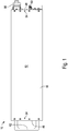
- FIG. 1 is a side view of a generator, in accordance with various embodiments of the present disclosure.
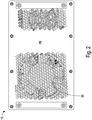
- the generator includes a housing 18 formed by bending a sheet of metal into a cuboid shaped sleeve and mounting a front panel 46 at one open end of the sleeve and a back panel 48 at the other open end of the sleeve to form a closed box shaped housing.
- the housing 18 is formed of materials for shielding internal electronic components of the generator 10 from EMI.
- the sleeve of the housing 18 forms relatively large faces 52 thereof, whilst the front panel 46 and the back panel 48 are located at, and define, relatively small faces 54 of the housing 18.
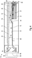
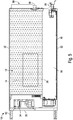
- FIG. 4 is a side cross-section of the generator of FIG. 1 , in accordance with various embodiments of the present disclosure.
- the generator 10 includes an air flow guidance plate 16 defining part of a cooling air duct 50 that divides the housing 18 into a high-power compartment 20 and a low-power compartment 22.
- the air flow guidance plate 16 is, preferably, made of sheet metal and extends at least partly between opposed faces 52 of the housing 18, thereby providing an EMI shielding function between the high and lower power compartments 20, 22.
- the high-power compartment 20 is shown in greater detail in the top cross-sectional view of FIG. 5 .
- the high-power compartment 20 includes a high-power circuit 12 including a power amplifier 14.
- the power amplifier 14 includes at least one transistor 26 (circuit shown schematically).
- the power amplifier 14 includes first and second transistors 26 connected in a push pull arrangement.
- the high-power circuit 12 includes a power transformer, as part of an output network, connected to the output (e.g. drains) of the at least one transistor 26.
- the high-power circuit 12 is configured to output amplifier output power through a power output connector 58 of the generator 10.
- the high-power circuit 12 includes a combiner for combining outputs from the first and second transistors 26.
- the high-power circuit 12 includes a sampler, such as a directional coupler, for providing measurement signals of output power of the generator.
- control signals generated in the low-power circuit 24 are provided to a pre-amplifier of the high-power circuit 12 for generating an RF signal that is amplified through the at least one transistor 26.
- the control signals thus control output of the power amplifier.
- the control signals are generated via the processor in order to minimize an error between the digitized measurement signals and a set point.
- the set point can be set through interface 60 (shown schematically) of the low-power circuit 24.
- the high-power circuit 12, particularly the transistors 26, requires active cooling to a significantly greater extent than the low-power circuit 24.
- cooling air flow passes, in major part, within a cooling air duct 50 dividing the high-power compartment 20 and the low power compartment 22 to cool the high-power circuit 12. Cooling air passes through a distribution of cooling air holes 28 from the low-power compartment 22 into the cooling air duct 50 to cool the low-power circuit 24.
- the generator 10 includes a heat sink 42 extending at least partly between the same opposed faces as the air flow guidance plate 16.
- the heat sink 42 has the high-power circuit 12 mounted thereon and is operative to draw heat away from the high-power circuit 12, particularly the at least one transistor 26.
- the heat sink 42 can be described as being located above the air flow guidance plate 16.
- the high-power circuit 12 is located on a top side of the heat sink 42.
- the low-power circuit 24 is mounted on an underside of the air flow guidance plate 16.
- a duct 50 is defined between the air flow guidance plate 16 and the heat sink 42 through which the cooling air passes.
- the heat sink 42 includes cooling fins 44 projecting from an underside of a solid base portion 70 thereof, as shown in FIG. 7 .
- the high-power circuit 12 is disposed upon the base portion 70 of the heat sink 42.
- the duct 50 is such as to have a reducing cross-sectional area from a higher cross-sectional area region 36 at one end of the high-power compartment 20 adjacent the power amplifier 14 to a reduced cross-sectional area region 38 at an opposed end of the high-power compartment 20 adjacent the low-power circuit 24.
- the reducing cross-sectional area of the duct 50 is constructed by reducing a spacing between an underside of the base portion 70 (see FIG. 7 ) of the heat sink 42 and an upper side of the air flow guidance plate 16.
- FIG. 7 the base portion 70
- the air flow guidance plate 16 includes a kink 40 such that part of the air flow guidance plate 16 on one side of the kink 40 is spaced farther away from the base portion 70 of the heat sink 42 and part of the air flow guidance plate 16 on the other side of the kink 40 is spaced closer to the air flow guidance plate 16, thereby respectively forming the higher cross-sectional area region 36 and the reduced cross-sectional area region 38.
- the heat sink 42 includes deeper cooling fins 64 that project relatively far from the base portion 70 and shallower cooling fins 66 that do not project as far from the base portion 70.
- the deeper cooling fins 64 are disposed in the higher cross-sectional area region 36 and the shallower cooling fins 66 are disposed in the reduced cross-sectional area region 38.
- the shallower cooling fins 66 represent a reduced cooling requirement upstream of cooling air flow as the power amplifier 14, and associated transistors 26, are located downstream of the cooling air flow adjacent to the deeper cooling fins 64.
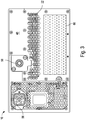
- the back panel 48 which is mounted at an opposite end of the housing 18 to the front panel 46, has a cooling air inlet/outlet 32, which includes holes through the back panel 48 allowing air to be expelled from/sucked into the housing 18 of the generator 10 by operation of the fan 34.
- the back panel 48 further includes the power output connector 58 for connecting a tool requiring amplified power output from the generator 10 (such as a plasma generating tool) and one or more control circuit interfaces 60 allowing connection to a user control device (such as a computer) for user input of settings to the low-power circuit 24.
- the back panel 48 further includes an AC input socket 56 into which an AC input plug is connected for powering the generator 10 via the power pack 68 (see FIG. 5 ) housed within the generator 10.
- the fan 34 is operable, when operated in one direction, so as to suck cooling air into the housing 18 through the cooling air outlet 32 and into the duct 50.
- the cooling air passes through the lower cross-sectional area region 38 over the shallower cooling fins 66 and then is directed by the kink 40 into the higher cross-sectional area region 36 so as to pass over the deeper cooling fins 64 and out of the housing 18 through the fan inlet/outlet 30.
- FIG. 6 illustrates a further aspect of the present disclosure including DC connectors 90 between the power pack 68 and the high-power circuit 12 (shown in block form).
- AC power is received at the AC input socket 56 and is converted to DC power (amongst other functions performed by the power pack 68) by an analog to digital power converter of the power pack 68.
- DC power is supplied through the DC connectors 90 of the power pack 68 to the high-power circuit 12.
- the DC power is routed to the at least one transistor 26 via at least one circuit trace.
- the DC connectors are located in a middle region (e.g. a mid-point) between opposed longitudinal ends of the power pack 68.
- the DC power is controlled via the low-power circuit 24, as are control signals supplied to the pre-amplifier of the high-power circuit 12, thereby controlling DC input and gate signals of the at least one transistor 26 to allow control of power output by the generator 10.
- Aspects of the present disclosure thus provide a compact generator 10 allowing EMI shielding between a low-power compartment 22 and a high-power compartment 20 and allowing EMI shielding between inside and outside the housing 18.
- Aspects of the present disclosure allow for efficient cooling of high- and low-power components using a single fan 34.
- the generators and power amplifiers described herein are useful to power plasma tools.
Landscapes
- Engineering & Computer Science (AREA)
- Microelectronics & Electronic Packaging (AREA)
- Physics & Mathematics (AREA)
- Thermal Sciences (AREA)
- Power Engineering (AREA)
- Cooling Or The Like Of Electrical Apparatus (AREA)
Applications Claiming Priority (1)
| Application Number | Priority Date | Filing Date | Title |
|---|---|---|---|
| GB1907195.0A GB2584117A (en) | 2019-05-22 | 2019-05-22 | Generator |
Publications (2)
| Publication Number | Publication Date |
|---|---|
| EP3745835A1 true EP3745835A1 (de) | 2020-12-02 |
| EP3745835B1 EP3745835B1 (de) | 2022-12-14 |
Family
ID=67385130
Family Applications (1)
| Application Number | Title | Priority Date | Filing Date |
|---|---|---|---|
| EP20174522.1A Active EP3745835B1 (de) | 2019-05-22 | 2020-05-13 | Generator |
Country Status (3)
| Country | Link |
|---|---|
| US (1) | US11516946B2 (de) |
| EP (1) | EP3745835B1 (de) |
| GB (1) | GB2584117A (de) |
Cited By (2)
| Publication number | Priority date | Publication date | Assignee | Title |
|---|---|---|---|---|
| EP4369377A1 (de) * | 2022-11-11 | 2024-05-15 | Comet AG | Radiofrequenzgenerator |
| IT202300021513A1 (it) * | 2023-10-16 | 2025-04-16 | M T Srl | Apparato per il trattamento di segnali elettrici a radiofrequenza |
Families Citing this family (5)
| Publication number | Priority date | Publication date | Assignee | Title |
|---|---|---|---|---|
| EP4272239B1 (de) * | 2020-12-30 | 2026-04-22 | Comet AG | Verfahren zur erzeugung eines hf-signals, regler, hf-generator und plasmavorrichtung |
| CN113133279B (zh) * | 2021-03-26 | 2022-10-25 | 联想(北京)有限公司 | 电子设备 |
| US12136840B2 (en) * | 2021-12-24 | 2024-11-05 | Motorola Solutions, Inc. | Device, battery and system to control battery power |
| FR3148350A1 (fr) * | 2023-04-26 | 2024-11-01 | Vitesco Technologies | Ensemble electronique a systeme de refroidissement integre, boitier electronique comportant un tel ensemble |
| DE102023111824A1 (de) * | 2023-05-05 | 2024-11-07 | TRUMPF Hüttinger GmbH + Co. KG | HF-Leistungsverstärkereinheit zur Kopplung von HF-Signalen für ein Plasmaprozessversorgungssystem und ein Plasmaprozesssystem |
Citations (4)
| Publication number | Priority date | Publication date | Assignee | Title |
|---|---|---|---|---|
| US4237521A (en) * | 1979-02-05 | 1980-12-02 | R. L. Drake Company | Housing for electronic assembly including internally mounted heat sink |
| EP0356991A2 (de) * | 1988-08-31 | 1990-03-07 | Hitachi, Ltd. | Wechselrichtervorrichtung |
| CN201160255Y (zh) * | 2008-02-03 | 2008-12-03 | 陈国金 | 多冷却风道结构的变频器 |
| US20130050939A1 (en) * | 2011-08-28 | 2013-02-28 | Purewave Networks, Inc. | Methods and system for effectively removing heat from a wireless base station |
Family Cites Families (10)
| Publication number | Priority date | Publication date | Assignee | Title |
|---|---|---|---|---|
| CH583980A5 (de) * | 1973-11-23 | 1977-01-14 | Zellweger Uster Ag | |
| JPH0795771A (ja) * | 1993-09-20 | 1995-04-07 | Sansha Electric Mfg Co Ltd | 電源装置の冷却構造 |
| US5689403A (en) * | 1994-12-27 | 1997-11-18 | Motorola, Inc. | Intercooled electronic device |
| US6253834B1 (en) * | 1998-10-28 | 2001-07-03 | Hewlett-Packard Company | Apparatus to enhance cooling of electronic device |
| JP2005341630A (ja) * | 2004-05-24 | 2005-12-08 | Mitsubishi Electric Corp | 電力変換装置 |
| US8611088B2 (en) * | 2011-11-16 | 2013-12-17 | Cooper Technologies Company | Mechanical heat pump for an electrical housing |
| US10455729B2 (en) * | 2014-01-10 | 2019-10-22 | Reno Technologies, Inc. | Enclosure cooling system |
| CN203674965U (zh) * | 2014-01-24 | 2014-06-25 | 周冬娟 | 具有隔离散热结构的变频器 |
| EP3018984B1 (de) * | 2014-11-04 | 2018-04-18 | ABB Schweiz AG | Elektrische Vorrichtung |
| US11464559B2 (en) * | 2017-12-28 | 2022-10-11 | Cilag Gmbh International | Estimating state of ultrasonic end effector and control system therefor |
-
2019
- 2019-05-22 GB GB1907195.0A patent/GB2584117A/en not_active Withdrawn
-
2020
- 2020-05-13 EP EP20174522.1A patent/EP3745835B1/de active Active
- 2020-05-21 US US16/879,942 patent/US11516946B2/en active Active
Patent Citations (4)
| Publication number | Priority date | Publication date | Assignee | Title |
|---|---|---|---|---|
| US4237521A (en) * | 1979-02-05 | 1980-12-02 | R. L. Drake Company | Housing for electronic assembly including internally mounted heat sink |
| EP0356991A2 (de) * | 1988-08-31 | 1990-03-07 | Hitachi, Ltd. | Wechselrichtervorrichtung |
| CN201160255Y (zh) * | 2008-02-03 | 2008-12-03 | 陈国金 | 多冷却风道结构的变频器 |
| US20130050939A1 (en) * | 2011-08-28 | 2013-02-28 | Purewave Networks, Inc. | Methods and system for effectively removing heat from a wireless base station |
Cited By (4)
| Publication number | Priority date | Publication date | Assignee | Title |
|---|---|---|---|---|
| EP4369377A1 (de) * | 2022-11-11 | 2024-05-15 | Comet AG | Radiofrequenzgenerator |
| WO2024099613A1 (en) * | 2022-11-11 | 2024-05-16 | Comet Ag | Radio frequency generator |
| IT202300021513A1 (it) * | 2023-10-16 | 2025-04-16 | M T Srl | Apparato per il trattamento di segnali elettrici a radiofrequenza |
| WO2025083536A1 (en) * | 2023-10-16 | 2025-04-24 | M.T. Srl | Radio frequency electrical signal combiner |
Also Published As
| Publication number | Publication date |
|---|---|
| US20200375068A1 (en) | 2020-11-26 |
| GB2584117A (en) | 2020-11-25 |
| EP3745835B1 (de) | 2022-12-14 |
| GB201907195D0 (en) | 2019-07-03 |
| US11516946B2 (en) | 2022-11-29 |
Similar Documents
| Publication | Publication Date | Title |
|---|---|---|
| US11516946B2 (en) | Generator | |
| Raab | Maximum efficiency and output of class-F power amplifiers | |
| KR102746117B1 (ko) | 플라즈마 제어 장치 | |
| US8286581B2 (en) | High frequency power source and its control method, and plasma processing apparatus | |
| US9837249B2 (en) | Radial waveguide systems and methods for post-match control of microwaves | |
| Chen et al. | Design and analysis of a stage-scaled distributed power amplifier | |
| US7259622B2 (en) | RF generator with phase controlled MOSFETs | |
| US20150270106A1 (en) | Radial waveguide systems and methods for post-match control of microwaves | |
| EP0975089A3 (de) | Stabiler Hochleistungsverstärker mit parallelem Hochspannungsmosfet | |
| JP2005527078A (ja) | 負荷不整合信頼性および安定性のあるvhfプラズマ処理のための方法および装置 | |
| TWI891635B (zh) | 射頻產生器、電漿處理系統、用於操作射頻產生控制器的方法、電腦編程元件及電腦可讀取介質 | |
| JP2018516515A (ja) | ソリッドステートマイクロ波発振器およびパワー増幅器 | |
| JP2006287817A (ja) | マイクロ波発生装置、マイクロ波供給装置、プラズマ処理装置及びマイクロ波発生方法 | |
| TW202035747A (zh) | 用於電漿處理設備的電壓波形產生器 | |
| AU2015249128B2 (en) | Electrical device | |
| US7265528B2 (en) | High-frequency power apparatus | |
| US10254359B2 (en) | Power amplifier device for a magnetic resonance device and magnetic resonance device | |
| KR20190103804A (ko) | 공냉 구조와 수냉 구조가 병합된 플라즈마 처리용 고주파 전력 발생장치 | |
| JP4805170B2 (ja) | 高周波電源装置 | |
| CN119135100A (zh) | 一种射频电源的驱动装置、射频电源、半导体工艺设备 | |
| WO2025126437A9 (ja) | プラズマ処理装置 | |
| CN214281331U (zh) | 一种w波段六倍频器 | |
| JP6455783B2 (ja) | 高周波電力システム及びこれを備えたプラズマ処理装置 | |
| JP5589300B2 (ja) | 加熱処理装置 | |
| JP5556035B2 (ja) | マイクロ波加熱装置 |
Legal Events
| Date | Code | Title | Description |
|---|---|---|---|
| PUAI | Public reference made under article 153(3) epc to a published international application that has entered the european phase |
Free format text: ORIGINAL CODE: 0009012 |
|
| STAA | Information on the status of an ep patent application or granted ep patent |
Free format text: STATUS: THE APPLICATION HAS BEEN PUBLISHED |
|
| AK | Designated contracting states |
Kind code of ref document: A1 Designated state(s): AL AT BE BG CH CY CZ DE DK EE ES FI FR GB GR HR HU IE IS IT LI LT LU LV MC MK MT NL NO PL PT RO RS SE SI SK SM TR |
|
| AX | Request for extension of the european patent |
Extension state: BA ME |
|
| STAA | Information on the status of an ep patent application or granted ep patent |
Free format text: STATUS: REQUEST FOR EXAMINATION WAS MADE |
|
| 17P | Request for examination filed |
Effective date: 20210531 |
|
| RBV | Designated contracting states (corrected) |
Designated state(s): AL AT BE BG CH CY CZ DE DK EE ES FI FR GB GR HR HU IE IS IT LI LT LU LV MC MK MT NL NO PL PT RO RS SE SI SK SM TR |
|
| GRAP | Despatch of communication of intention to grant a patent |
Free format text: ORIGINAL CODE: EPIDOSNIGR1 |
|
| STAA | Information on the status of an ep patent application or granted ep patent |
Free format text: STATUS: GRANT OF PATENT IS INTENDED |
|
| RIC1 | Information provided on ipc code assigned before grant |
Ipc: H05K 7/20 20060101AFI20220608BHEP |
|
| INTG | Intention to grant announced |
Effective date: 20220706 |
|
| GRAS | Grant fee paid |
Free format text: ORIGINAL CODE: EPIDOSNIGR3 |
|
| GRAA | (expected) grant |
Free format text: ORIGINAL CODE: 0009210 |
|
| STAA | Information on the status of an ep patent application or granted ep patent |
Free format text: STATUS: THE PATENT HAS BEEN GRANTED |
|
| AK | Designated contracting states |
Kind code of ref document: B1 Designated state(s): AL AT BE BG CH CY CZ DE DK EE ES FI FR GB GR HR HU IE IS IT LI LT LU LV MC MK MT NL NO PL PT RO RS SE SI SK SM TR |
|
| REG | Reference to a national code |
Ref country code: GB Ref legal event code: FG4D |
|
| REG | Reference to a national code |
Ref country code: CH Ref legal event code: EP |
|
| REG | Reference to a national code |
Ref country code: DE Ref legal event code: R096 Ref document number: 602020006868 Country of ref document: DE |
|
| REG | Reference to a national code |
Ref country code: IE Ref legal event code: FG4D |
|
| REG | Reference to a national code |
Ref country code: AT Ref legal event code: REF Ref document number: 1538446 Country of ref document: AT Kind code of ref document: T Effective date: 20230115 |
|
| REG | Reference to a national code |
Ref country code: LT Ref legal event code: MG9D |
|
| REG | Reference to a national code |
Ref country code: NL Ref legal event code: MP Effective date: 20221214 |
|
| PG25 | Lapsed in a contracting state [announced via postgrant information from national office to epo] |
Ref country code: SE Free format text: LAPSE BECAUSE OF FAILURE TO SUBMIT A TRANSLATION OF THE DESCRIPTION OR TO PAY THE FEE WITHIN THE PRESCRIBED TIME-LIMIT Effective date: 20221214 Ref country code: NO Free format text: LAPSE BECAUSE OF FAILURE TO SUBMIT A TRANSLATION OF THE DESCRIPTION OR TO PAY THE FEE WITHIN THE PRESCRIBED TIME-LIMIT Effective date: 20230314 Ref country code: LT Free format text: LAPSE BECAUSE OF FAILURE TO SUBMIT A TRANSLATION OF THE DESCRIPTION OR TO PAY THE FEE WITHIN THE PRESCRIBED TIME-LIMIT Effective date: 20221214 Ref country code: FI Free format text: LAPSE BECAUSE OF FAILURE TO SUBMIT A TRANSLATION OF THE DESCRIPTION OR TO PAY THE FEE WITHIN THE PRESCRIBED TIME-LIMIT Effective date: 20221214 |
|
| REG | Reference to a national code |
Ref country code: AT Ref legal event code: MK05 Ref document number: 1538446 Country of ref document: AT Kind code of ref document: T Effective date: 20221214 |
|
| PG25 | Lapsed in a contracting state [announced via postgrant information from national office to epo] |
Ref country code: RS Free format text: LAPSE BECAUSE OF FAILURE TO SUBMIT A TRANSLATION OF THE DESCRIPTION OR TO PAY THE FEE WITHIN THE PRESCRIBED TIME-LIMIT Effective date: 20221214 Ref country code: LV Free format text: LAPSE BECAUSE OF FAILURE TO SUBMIT A TRANSLATION OF THE DESCRIPTION OR TO PAY THE FEE WITHIN THE PRESCRIBED TIME-LIMIT Effective date: 20221214 Ref country code: HR Free format text: LAPSE BECAUSE OF FAILURE TO SUBMIT A TRANSLATION OF THE DESCRIPTION OR TO PAY THE FEE WITHIN THE PRESCRIBED TIME-LIMIT Effective date: 20221214 Ref country code: GR Free format text: LAPSE BECAUSE OF FAILURE TO SUBMIT A TRANSLATION OF THE DESCRIPTION OR TO PAY THE FEE WITHIN THE PRESCRIBED TIME-LIMIT Effective date: 20230315 |
|
| P01 | Opt-out of the competence of the unified patent court (upc) registered |
Effective date: 20230523 |
|
| PG25 | Lapsed in a contracting state [announced via postgrant information from national office to epo] |
Ref country code: NL Free format text: LAPSE BECAUSE OF FAILURE TO SUBMIT A TRANSLATION OF THE DESCRIPTION OR TO PAY THE FEE WITHIN THE PRESCRIBED TIME-LIMIT Effective date: 20221214 |
|
| PG25 | Lapsed in a contracting state [announced via postgrant information from national office to epo] |
Ref country code: SM Free format text: LAPSE BECAUSE OF FAILURE TO SUBMIT A TRANSLATION OF THE DESCRIPTION OR TO PAY THE FEE WITHIN THE PRESCRIBED TIME-LIMIT Effective date: 20221214 Ref country code: RO Free format text: LAPSE BECAUSE OF FAILURE TO SUBMIT A TRANSLATION OF THE DESCRIPTION OR TO PAY THE FEE WITHIN THE PRESCRIBED TIME-LIMIT Effective date: 20221214 Ref country code: PT Free format text: LAPSE BECAUSE OF FAILURE TO SUBMIT A TRANSLATION OF THE DESCRIPTION OR TO PAY THE FEE WITHIN THE PRESCRIBED TIME-LIMIT Effective date: 20230414 Ref country code: ES Free format text: LAPSE BECAUSE OF FAILURE TO SUBMIT A TRANSLATION OF THE DESCRIPTION OR TO PAY THE FEE WITHIN THE PRESCRIBED TIME-LIMIT Effective date: 20221214 Ref country code: EE Free format text: LAPSE BECAUSE OF FAILURE TO SUBMIT A TRANSLATION OF THE DESCRIPTION OR TO PAY THE FEE WITHIN THE PRESCRIBED TIME-LIMIT Effective date: 20221214 Ref country code: CZ Free format text: LAPSE BECAUSE OF FAILURE TO SUBMIT A TRANSLATION OF THE DESCRIPTION OR TO PAY THE FEE WITHIN THE PRESCRIBED TIME-LIMIT Effective date: 20221214 Ref country code: AT Free format text: LAPSE BECAUSE OF FAILURE TO SUBMIT A TRANSLATION OF THE DESCRIPTION OR TO PAY THE FEE WITHIN THE PRESCRIBED TIME-LIMIT Effective date: 20221214 |
|
| PG25 | Lapsed in a contracting state [announced via postgrant information from national office to epo] |
Ref country code: SK Free format text: LAPSE BECAUSE OF FAILURE TO SUBMIT A TRANSLATION OF THE DESCRIPTION OR TO PAY THE FEE WITHIN THE PRESCRIBED TIME-LIMIT Effective date: 20221214 Ref country code: PL Free format text: LAPSE BECAUSE OF FAILURE TO SUBMIT A TRANSLATION OF THE DESCRIPTION OR TO PAY THE FEE WITHIN THE PRESCRIBED TIME-LIMIT Effective date: 20221214 Ref country code: IS Free format text: LAPSE BECAUSE OF FAILURE TO SUBMIT A TRANSLATION OF THE DESCRIPTION OR TO PAY THE FEE WITHIN THE PRESCRIBED TIME-LIMIT Effective date: 20230414 Ref country code: AL Free format text: LAPSE BECAUSE OF FAILURE TO SUBMIT A TRANSLATION OF THE DESCRIPTION OR TO PAY THE FEE WITHIN THE PRESCRIBED TIME-LIMIT Effective date: 20221214 |
|
| REG | Reference to a national code |
Ref country code: DE Ref legal event code: R097 Ref document number: 602020006868 Country of ref document: DE |
|
| PLBE | No opposition filed within time limit |
Free format text: ORIGINAL CODE: 0009261 |
|
| STAA | Information on the status of an ep patent application or granted ep patent |
Free format text: STATUS: NO OPPOSITION FILED WITHIN TIME LIMIT |
|
| PG25 | Lapsed in a contracting state [announced via postgrant information from national office to epo] |
Ref country code: DK Free format text: LAPSE BECAUSE OF FAILURE TO SUBMIT A TRANSLATION OF THE DESCRIPTION OR TO PAY THE FEE WITHIN THE PRESCRIBED TIME-LIMIT Effective date: 20221214 |
|
| 26N | No opposition filed |
Effective date: 20230915 |
|
| PG25 | Lapsed in a contracting state [announced via postgrant information from national office to epo] |
Ref country code: SI Free format text: LAPSE BECAUSE OF FAILURE TO SUBMIT A TRANSLATION OF THE DESCRIPTION OR TO PAY THE FEE WITHIN THE PRESCRIBED TIME-LIMIT Effective date: 20221214 |
|
| PG25 | Lapsed in a contracting state [announced via postgrant information from national office to epo] |
Ref country code: MC Free format text: LAPSE BECAUSE OF FAILURE TO SUBMIT A TRANSLATION OF THE DESCRIPTION OR TO PAY THE FEE WITHIN THE PRESCRIBED TIME-LIMIT Effective date: 20221214 |
|
| REG | Reference to a national code |
Ref country code: BE Ref legal event code: MM Effective date: 20230531 |
|
| PG25 | Lapsed in a contracting state [announced via postgrant information from national office to epo] |
Ref country code: MC Free format text: LAPSE BECAUSE OF FAILURE TO SUBMIT A TRANSLATION OF THE DESCRIPTION OR TO PAY THE FEE WITHIN THE PRESCRIBED TIME-LIMIT Effective date: 20221214 Ref country code: LU Free format text: LAPSE BECAUSE OF NON-PAYMENT OF DUE FEES Effective date: 20230513 |
|
| REG | Reference to a national code |
Ref country code: IE Ref legal event code: MM4A |
|
| PG25 | Lapsed in a contracting state [announced via postgrant information from national office to epo] |
Ref country code: IE Free format text: LAPSE BECAUSE OF NON-PAYMENT OF DUE FEES Effective date: 20230513 |
|
| PG25 | Lapsed in a contracting state [announced via postgrant information from national office to epo] |
Ref country code: IE Free format text: LAPSE BECAUSE OF NON-PAYMENT OF DUE FEES Effective date: 20230513 |
|
| PG25 | Lapsed in a contracting state [announced via postgrant information from national office to epo] |
Ref country code: IT Free format text: LAPSE BECAUSE OF FAILURE TO SUBMIT A TRANSLATION OF THE DESCRIPTION OR TO PAY THE FEE WITHIN THE PRESCRIBED TIME-LIMIT Effective date: 20221214 Ref country code: BE Free format text: LAPSE BECAUSE OF NON-PAYMENT OF DUE FEES Effective date: 20230531 |
|
| PG25 | Lapsed in a contracting state [announced via postgrant information from national office to epo] |
Ref country code: BG Free format text: LAPSE BECAUSE OF FAILURE TO SUBMIT A TRANSLATION OF THE DESCRIPTION OR TO PAY THE FEE WITHIN THE PRESCRIBED TIME-LIMIT Effective date: 20221214 |
|
| PG25 | Lapsed in a contracting state [announced via postgrant information from national office to epo] |
Ref country code: BG Free format text: LAPSE BECAUSE OF FAILURE TO SUBMIT A TRANSLATION OF THE DESCRIPTION OR TO PAY THE FEE WITHIN THE PRESCRIBED TIME-LIMIT Effective date: 20221214 |
|
| PGFP | Annual fee paid to national office [announced via postgrant information from national office to epo] |
Ref country code: DE Payment date: 20250515 Year of fee payment: 6 |
|
| PGFP | Annual fee paid to national office [announced via postgrant information from national office to epo] |
Ref country code: GB Payment date: 20250522 Year of fee payment: 6 |
|
| PGFP | Annual fee paid to national office [announced via postgrant information from national office to epo] |
Ref country code: FR Payment date: 20250521 Year of fee payment: 6 |
|
| PGFP | Annual fee paid to national office [announced via postgrant information from national office to epo] |
Ref country code: CH Payment date: 20250601 Year of fee payment: 6 |
|
| PG25 | Lapsed in a contracting state [announced via postgrant information from national office to epo] |
Ref country code: CY Free format text: LAPSE BECAUSE OF FAILURE TO SUBMIT A TRANSLATION OF THE DESCRIPTION OR TO PAY THE FEE WITHIN THE PRESCRIBED TIME-LIMIT; INVALID AB INITIO Effective date: 20200513 |
|
| PG25 | Lapsed in a contracting state [announced via postgrant information from national office to epo] |
Ref country code: HU Free format text: LAPSE BECAUSE OF FAILURE TO SUBMIT A TRANSLATION OF THE DESCRIPTION OR TO PAY THE FEE WITHIN THE PRESCRIBED TIME-LIMIT; INVALID AB INITIO Effective date: 20200513 |
|
| PG25 | Lapsed in a contracting state [announced via postgrant information from national office to epo] |
Ref country code: TR Free format text: LAPSE BECAUSE OF FAILURE TO SUBMIT A TRANSLATION OF THE DESCRIPTION OR TO PAY THE FEE WITHIN THE PRESCRIBED TIME-LIMIT Effective date: 20221214 |