EP3745544A1 - Système de bague de frottement à refroidissement amélioré - Google Patents
Système de bague de frottement à refroidissement amélioré Download PDFInfo
- Publication number
- EP3745544A1 EP3745544A1 EP19177085.8A EP19177085A EP3745544A1 EP 3745544 A1 EP3745544 A1 EP 3745544A1 EP 19177085 A EP19177085 A EP 19177085A EP 3745544 A1 EP3745544 A1 EP 3745544A1
- Authority
- EP
- European Patent Office
- Prior art keywords
- slip ring
- brush
- ring system
- brush holder
- brushes
- Prior art date
- Legal status (The legal status is an assumption and is not a legal conclusion. Google has not performed a legal analysis and makes no representation as to the accuracy of the status listed.)
- Withdrawn
Links
Images


Classifications
-
- H—ELECTRICITY
- H01—ELECTRIC ELEMENTS
- H01R—ELECTRICALLY-CONDUCTIVE CONNECTIONS; STRUCTURAL ASSOCIATIONS OF A PLURALITY OF MUTUALLY-INSULATED ELECTRICAL CONNECTING ELEMENTS; COUPLING DEVICES; CURRENT COLLECTORS
- H01R39/00—Rotary current collectors, distributors or interrupters
- H01R39/02—Details for dynamo electric machines
- H01R39/38—Brush holders
-
- H—ELECTRICITY
- H02—GENERATION; CONVERSION OR DISTRIBUTION OF ELECTRIC POWER
- H02K—DYNAMO-ELECTRIC MACHINES
- H02K9/00—Arrangements for cooling or ventilating
- H02K9/28—Cooling of commutators, slip-rings or brushes e.g. by ventilating
-
- F—MECHANICAL ENGINEERING; LIGHTING; HEATING; WEAPONS; BLASTING
- F03—MACHINES OR ENGINES FOR LIQUIDS; WIND, SPRING, OR WEIGHT MOTORS; PRODUCING MECHANICAL POWER OR A REACTIVE PROPULSIVE THRUST, NOT OTHERWISE PROVIDED FOR
- F03D—WIND MOTORS
- F03D80/00—Details, components or accessories not provided for in groups F03D1/00 - F03D17/00
- F03D80/60—Cooling or heating of wind motors
-
- H—ELECTRICITY
- H01—ELECTRIC ELEMENTS
- H01R—ELECTRICALLY-CONDUCTIVE CONNECTIONS; STRUCTURAL ASSOCIATIONS OF A PLURALITY OF MUTUALLY-INSULATED ELECTRICAL CONNECTING ELEMENTS; COUPLING DEVICES; CURRENT COLLECTORS
- H01R39/00—Rotary current collectors, distributors or interrupters
- H01R39/02—Details for dynamo electric machines
- H01R39/08—Slip-rings
-
- H—ELECTRICITY
- H02—GENERATION; CONVERSION OR DISTRIBUTION OF ELECTRIC POWER
- H02K—DYNAMO-ELECTRIC MACHINES
- H02K5/00—Casings; Enclosures; Supports
- H02K5/04—Casings or enclosures characterised by the shape, form or construction thereof
- H02K5/14—Means for supporting or protecting brushes or brush holders
- H02K5/141—Means for supporting or protecting brushes or brush holders for cooperation with slip-rings
-
- H—ELECTRICITY
- H02—GENERATION; CONVERSION OR DISTRIBUTION OF ELECTRIC POWER
- H02K—DYNAMO-ELECTRIC MACHINES
- H02K7/00—Arrangements for handling mechanical energy structurally associated with dynamo-electric machines, e.g. structural association with mechanical driving motors or auxiliary dynamo-electric machines
- H02K7/18—Structural association of electric generators with mechanical driving motors, e.g. with turbines
- H02K7/1807—Rotary generators
- H02K7/1823—Rotary generators structurally associated with turbines or similar engines
- H02K7/183—Rotary generators structurally associated with turbines or similar engines wherein the turbine is a wind turbine
-
- H—ELECTRICITY
- H02—GENERATION; CONVERSION OR DISTRIBUTION OF ELECTRIC POWER
- H02K—DYNAMO-ELECTRIC MACHINES
- H02K9/00—Arrangements for cooling or ventilating
- H02K9/26—Structural association of machines with devices for cleaning or drying cooling medium, e.g. with filters
-
- F—MECHANICAL ENGINEERING; LIGHTING; HEATING; WEAPONS; BLASTING
- F05—INDEXING SCHEMES RELATING TO ENGINES OR PUMPS IN VARIOUS SUBCLASSES OF CLASSES F01-F04
- F05B—INDEXING SCHEME RELATING TO WIND, SPRING, WEIGHT, INERTIA OR LIKE MOTORS, TO MACHINES OR ENGINES FOR LIQUIDS COVERED BY SUBCLASSES F03B, F03D AND F03G
- F05B2220/00—Application
- F05B2220/70—Application in combination with
- F05B2220/706—Application in combination with an electrical generator
-
- F—MECHANICAL ENGINEERING; LIGHTING; HEATING; WEAPONS; BLASTING
- F05—INDEXING SCHEMES RELATING TO ENGINES OR PUMPS IN VARIOUS SUBCLASSES OF CLASSES F01-F04
- F05B—INDEXING SCHEME RELATING TO WIND, SPRING, WEIGHT, INERTIA OR LIKE MOTORS, TO MACHINES OR ENGINES FOR LIQUIDS COVERED BY SUBCLASSES F03B, F03D AND F03G
- F05B2260/00—Function
- F05B2260/20—Heat transfer, e.g. cooling
- F05B2260/232—Heat transfer, e.g. cooling characterised by the cooling medium
-
- Y—GENERAL TAGGING OF NEW TECHNOLOGICAL DEVELOPMENTS; GENERAL TAGGING OF CROSS-SECTIONAL TECHNOLOGIES SPANNING OVER SEVERAL SECTIONS OF THE IPC; TECHNICAL SUBJECTS COVERED BY FORMER USPC CROSS-REFERENCE ART COLLECTIONS [XRACs] AND DIGESTS
- Y02—TECHNOLOGIES OR APPLICATIONS FOR MITIGATION OR ADAPTATION AGAINST CLIMATE CHANGE
- Y02E—REDUCTION OF GREENHOUSE GAS [GHG] EMISSIONS, RELATED TO ENERGY GENERATION, TRANSMISSION OR DISTRIBUTION
- Y02E10/00—Energy generation through renewable energy sources
- Y02E10/70—Wind energy
- Y02E10/72—Wind turbines with rotation axis in wind direction
Definitions
- the invention relates to a brush holder of a slip ring system of a dynamoelectric excited machine, a carrier segment with such brush holders, a slip ring system with such carrier segments, a ventilation system of a slip ring system and a dynamoelectric machine.
- Slip ring systems are used to introduce electrical excitation into the rotating part of a dynamo-electric machine, i.e. the rotor.
- the electrical power that can be transmitted becomes higher and higher.
- the temperatures, in particular of the brushes and the brush holders rise considerably. Excessive temperature increases cause damage to the slip ring system and also to the brushes.
- slip ring bodies with larger outer diameters are used from a certain size of dynamoelectric machine.
- the brush holders used which are also referred to as brush bridges, are dimensioned correspondingly larger.
- this performance-related increase also leads to a unwanted enlargement of the external dimensions of the dynamo-electric machine.
- the invention is based on the object of creating a slip ring system which, even with a comparatively compact design of the slip ring system, does not exceed the maximum permissible temperatures of the slip ring system and its components.
- the problem is solved by a brush holder of a slip ring system, an electrically excited dynamo-electric machine, the brush holder providing means for cooling brushes in the brush holder and / or the brush holder.
- each brush in the brush holder can now be cooled comparatively well, so that the power that can be transmitted to a rotor of a dynamo-electric machine can be increased.
- the problem posed is also achieved by means of a carrier segment with one or more brush holders according to the invention.
- the problem posed is also achieved by means of a slip ring system with one or more carrier segments according to the invention. Due to the improved cooling performance of the brushes and / or brush holder and thus of a carrier system, the slip ring system is also thermally almost uniformly loaded and adequately cooled, so that the slip ring system has a compact design.
- the problem posed is also achieved by a ventilation system with a slip ring system according to the invention.
- the ventilation system guides air within the slip ring system, which is designed to be closed or open, in such a way that brush holders and / or brush pockets and / or brushes can be cooled. This is achieved in that the required flow of cooling air, generated by radial and / or axial fans, is provided inside or on the slip ring system.
- the problem posed is also achieved by a dynamoelectric machine, in particular a generator of a wind power plant with a ventilation system according to the invention or a slip ring system according to the invention.
- the cooling surface of the brush pockets and / or the overflow area of the brushes is enlarged by a cooling air flow.
- the ribs can be designed as rectangular ribs, triangular ribs, trapezoidal ribs, concave or convex parabolic ribs, just as the needles can be designed as cylindrical-conical, concave, parabolic or convex parabolic needles or knobs.
- At least one fan arranged within the slip ring system guides air past the brush pocket and brush holders, which have surface-enlarging structures.
- Corresponding fans can advantageously be used, which generate a radial air flow and / or a cooling air flow running in the circumferential direction. This can be supported in that the knobs, needles or ribs are arranged accordingly in the flow direction of a generated cooling air flow.
- a ventilation of the slip ring system is thus possible through a draft ventilation, as well as or in addition through an external ventilation.
- the cooling air flow or the cooling air flows are generated by fans in and / or on the slip ring system.
- the outside air which is sucked into the slip ring system as cooler air via the cooling openings, is guided within the slip ring system via cooling air ducts or guiding devices, among other things, directly to the brush pocket, the brush holder and / or the brushes. Since these are the critical heat sources, they are now directly cooled with the so-called cold air flow.
- cooler ambient air is sucked in and distributed in the slip ring system by fans and / or guide devices, in particular to the heat sources.
- the air that is now heated in the slip ring system on the brush pockets, the brush holders and / or the brushes is discharged from the slip ring space into the environment.
- the air flow is generated by suction and / or pressure fans that are designed as axial or radial fans.
- Filter mats at the entrance and / or exit can filter the polluted air.
- the internal cooling circuit recooled in an intercooler is distributed by fans and / or guide devices, in particular to the heat sources within the closed housing of the slip ring system.
- the air that is now heated in the slip ring system on the brush pockets, the brush holders and / or the brushes is passed from the slip ring space into the intercooler.
- This air flow is generated by suction and / or pressure fans, which are designed as axial or radial fans and are arranged within the housing of the slip ring system.
- FIG 1 shows a brush holder 1 with brush pockets 7, in this case three parallel receiving pockets into which brushes 8 can be inserted.
- the brush pockets 7 are only provided with recesses 11 in order, in particular, to facilitate cooling of the brushes 8.
- FIG 2 shows a carrier segment 2 on which several brush holders 1 are arranged, one carrier segment 2 being provided for one electrical phase U, V, M each of a slip ring system 13.
- the brush pockets 7 have ribs 9 which run essentially tangentially to an axis 19.
- FIG 3 shows a mixture of the shape of the course of the ribs 9, in that on the one hand a tangential shape and a radial shape is present on a brush holder 1. A flow of cooling air is thus not only guided in the tangential direction but also in the radial direction, which further improves the cooling of this brush holder 1.
- FIG 4 shows a further carrier segment 2 with brush pockets 7, the surface of which is provided with needles 10 or knobs in order to enlarge the surface and thus improve the cooling.
- a flow of cooling air 20 can be guided in both the tangential and radial directions.
- FIG 5 shows a brush pocket 7, the holding function of which has been minimized by additionally providing a predetermined number of recesses 11 on the brush pocket 7. Needles 10 are attached to the remaining guides of the brush 8, so that direct cooling of the brushes 8 and cooling of the brush pocket 7 are made possible.
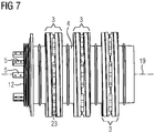
- FIG 6 shows a slip ring unit with three individual slip rings 3 which are arranged axially one behind the other and are separated from one another by insulation 4. Each slip ring 3 is to proceed for an electrical phase U or V or M. At one axial end of this arrangement there is a support ring 12 from which contact points 5 protrude axially parallel and which allow an electrical connection of a winding system 17 of a rotor 16.
- FIG 7 shows the slip ring system 3 according to FIG FIG 6 .
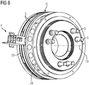
- FIG 8 shows a single slip ring 3, for example phase U of a slip ring unit with the elements mentioned above, such as contact points 5, support ring 12, radial cooling openings 23 and axial cooling openings 24. It is also shown there in principle how a brush holder 1 can be arranged on slip ring 3.
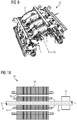
- FIG 9 shows a brush bridge in which four carrier segments 2 are arranged axially one behind the other, with, for example, three carrier segments 2 each assigned to an electrical phase U, V, M and one carrier segment 2 having brushes 8 for grounding.
- FIG 10 shows a basic illustration of the arrangement of a slip ring system 13 on a shaft 18, the slip rings 3 rotating about the axis 19 just like the rotor 16.
- the slip ring system 13 is positioned on the end face of the rotor 16.
- a slip ring system 13 has a brush bridge with carrier segments 2 and a slip ring unit with slip rings 3.
- a carrier segment 2 has one or more brush holders 1, each of which can be assigned to a slip ring 3.
- Each brush holder 1 has one or more brush pockets 7 in which the brushes 8 are positioned.
- the brushes 8 are pressed onto the slip ring 3 by a device not shown in detail in order to ensure proper contact. Furthermore, the brushes 8 are monitored with regard to their wear by a corresponding device.
- the slip ring system 13 has contact points 5, support ring 12, radial cooling openings 23 and axial cooling openings 24.
- cooler ambient air is preferably sucked in by fans and distributed in slip ring system 13 by further fans and / or guide devices, in particular to the heat sources.
- the now in the slip ring system 13 on the brush pockets 7, the Brush holders 1 and / or the brushes 8 heated air is passed from the slip ring space into the environment.
- the air flow is generated by suction and / or pressure fans, which are designed as axial or radial fans and are arranged on or in the slip ring space.
- Filter mats at the entrance and / or exit can filter the polluted air.
- the internal cooling circuit recooled in an intercooler is distributed by fans and / or guide devices, in particular to the heat sources within the closed housing of the slip ring system 13.
- the air that is now heated in the slip ring system 13 on the brush pockets 7, the brush holders 1 and / or the brushes 8 is passed out of the slip ring space into the intercooler (not shown in detail).
- This air flow is generated by suction and / or pressure fans, which are designed as axial or radial fans and are arranged within the housing of the slip ring system 13.
- Such compact slip ring systems 13 are particularly suitable for dynamoelectric machines 14 with a comparatively high output in the MW range.
- These machines 14 are particularly suitable as generators, in particular double-fed asynchronous machines for wind turbines, since the space available in a nacelle of a wind turbine is comparatively tight, and nevertheless comparatively large powers are to be transmitted in the generator.
Landscapes
- Engineering & Computer Science (AREA)
- Power Engineering (AREA)
- Life Sciences & Earth Sciences (AREA)
- Sustainable Development (AREA)
- Sustainable Energy (AREA)
- Physics & Mathematics (AREA)
- Thermal Sciences (AREA)
- Chemical & Material Sciences (AREA)
- Combustion & Propulsion (AREA)
- Mechanical Engineering (AREA)
- General Engineering & Computer Science (AREA)
- Motor Or Generator Cooling System (AREA)
- Motor Or Generator Current Collectors (AREA)
Priority Applications (7)
| Application Number | Priority Date | Filing Date | Title |
|---|---|---|---|
| EP19177085.8A EP3745544A1 (fr) | 2019-05-28 | 2019-05-28 | Système de bague de frottement à refroidissement amélioré |
| EP20718258.5A EP3977572A1 (fr) | 2019-05-28 | 2020-04-03 | Système de bague collectrice à refroidissement amélioré |
| CA3138621A CA3138621A1 (fr) | 2019-05-28 | 2020-04-03 | Systeme de bague collectrice a refroidissement ameliore |
| US17/613,352 US11916467B2 (en) | 2019-05-28 | 2020-04-03 | Slip ring system with improved cooling |
| CN202080039385.6A CN113892215B (zh) | 2019-05-28 | 2020-04-03 | 改善冷却的滑环系统 |
| BR112021020887A BR112021020887A2 (pt) | 2019-05-28 | 2020-04-03 | Sistema de ventilação de um sistema de anel deslizante, e, máquina dinamoelétrica |
| PCT/EP2020/059546 WO2020239301A1 (fr) | 2019-05-28 | 2020-04-03 | Système de bague collectrice à refroidissement amélioré |
Applications Claiming Priority (1)
| Application Number | Priority Date | Filing Date | Title |
|---|---|---|---|
| EP19177085.8A EP3745544A1 (fr) | 2019-05-28 | 2019-05-28 | Système de bague de frottement à refroidissement amélioré |
Publications (1)
| Publication Number | Publication Date |
|---|---|
| EP3745544A1 true EP3745544A1 (fr) | 2020-12-02 |
Family
ID=66676261
Family Applications (2)
| Application Number | Title | Priority Date | Filing Date |
|---|---|---|---|
| EP19177085.8A Withdrawn EP3745544A1 (fr) | 2019-05-28 | 2019-05-28 | Système de bague de frottement à refroidissement amélioré |
| EP20718258.5A Pending EP3977572A1 (fr) | 2019-05-28 | 2020-04-03 | Système de bague collectrice à refroidissement amélioré |
Family Applications After (1)
| Application Number | Title | Priority Date | Filing Date |
|---|---|---|---|
| EP20718258.5A Pending EP3977572A1 (fr) | 2019-05-28 | 2020-04-03 | Système de bague collectrice à refroidissement amélioré |
Country Status (6)
| Country | Link |
|---|---|
| US (1) | US11916467B2 (fr) |
| EP (2) | EP3745544A1 (fr) |
| CN (1) | CN113892215B (fr) |
| BR (1) | BR112021020887A2 (fr) |
| CA (1) | CA3138621A1 (fr) |
| WO (1) | WO2020239301A1 (fr) |
Cited By (3)
| Publication number | Priority date | Publication date | Assignee | Title |
|---|---|---|---|---|
| US20210167670A1 (en) * | 2018-07-27 | 2021-06-03 | Flender Gmbh | Holding device for a slip ring unit, slip ring bridge, slip ring unit, electric machine, and wind turbine |
| CN113708570A (zh) * | 2021-08-18 | 2021-11-26 | 西安中车永电捷力风能有限公司 | 一种双馈风力发电机滑环室冷却结构 |
| US20220224204A1 (en) * | 2019-05-28 | 2022-07-14 | Flender Gmbh | Slip ring system with improved cooling |
Citations (3)
| Publication number | Priority date | Publication date | Assignee | Title |
|---|---|---|---|---|
| JPS5028606A (fr) * | 1973-07-20 | 1975-03-24 | ||
| EP3291423A1 (fr) * | 2016-08-29 | 2018-03-07 | Siemens Aktiengesellschaft | Systeme de bague collectrice |
| US20180166844A1 (en) * | 2015-05-29 | 2018-06-14 | Siemens Aktiengesellschaft | Arrangement for guiding and/or holding electrically conductive sliding contact elements |
Family Cites Families (21)
| Publication number | Priority date | Publication date | Assignee | Title |
|---|---|---|---|---|
| CH571283A5 (fr) * | 1974-04-17 | 1975-12-31 | Bbc Brown Boveri & Cie | |
| US4137474A (en) | 1974-06-04 | 1979-01-30 | Kraftwerk Union Aktiengesellschaft | Gas-cooled slip ring for electrical machines |
| DE2848410A1 (de) * | 1978-11-08 | 1980-05-29 | Bosch Gmbh Robert | Abdeckhaube fuer elektrische maschinen |
| JP3430027B2 (ja) * | 1998-09-04 | 2003-07-28 | 三菱電機株式会社 | 車両用交流発電機 |
| JP4106852B2 (ja) * | 2000-04-14 | 2008-06-25 | 株式会社デンソー | 車両用交流発電機 |
| GB2367193A (en) * | 2000-09-20 | 2002-03-27 | Johnson Electric Sa | Cooling brushes in a miniature electric motor |
| DE10154866A1 (de) * | 2001-11-08 | 2003-05-28 | Bosch Gmbh Robert | Elektrische Maschine, vorzugsweise Drehstromgenerator für Kraftfahrzeuge |
| JP4471126B2 (ja) * | 2006-09-07 | 2010-06-02 | 株式会社デンソー | 車両用交流発電機 |
| US7843080B2 (en) * | 2009-05-11 | 2010-11-30 | General Electric Company | Cooling system and wind turbine incorporating same |
| JP4810589B2 (ja) * | 2009-05-28 | 2011-11-09 | 三菱電機株式会社 | 回転電機 |
| EP2688185B1 (fr) * | 2011-06-07 | 2018-01-17 | Mitsubishi Electric Corporation | Machine électrique tournante |
| CN103609007A (zh) | 2011-07-28 | 2014-02-26 | 三菱电机株式会社 | 旋转电机 |
| WO2013061404A1 (fr) * | 2011-10-25 | 2013-05-02 | 三菱電機株式会社 | Machine électrique tournante |
| JP5634618B2 (ja) * | 2011-11-09 | 2014-12-03 | 三菱電機株式会社 | 回転電機 |
| WO2013069105A1 (fr) * | 2011-11-09 | 2013-05-16 | 三菱電機株式会社 | Machine électrique rotative |
| JP5542977B1 (ja) * | 2013-01-24 | 2014-07-09 | 三菱電機株式会社 | 回転電機 |
| JP5721794B2 (ja) * | 2013-08-26 | 2015-05-20 | 三菱電機株式会社 | 制御装置一体型回転電機 |
| CN207732237U (zh) | 2017-12-29 | 2018-08-14 | 江苏民威电碳科技有限公司 | 一种整流性能优良的电刷 |
| CN208046397U (zh) | 2018-02-13 | 2018-11-02 | 西门子公司 | 滑环结构及滑环电机 |
| EP3537577A1 (fr) * | 2018-03-08 | 2019-09-11 | Siemens Aktiengesellschaft | Unité de bague collectrice pourvue de système de refroidissement actif |
| EP3745544A1 (fr) * | 2019-05-28 | 2020-12-02 | Siemens Aktiengesellschaft | Système de bague de frottement à refroidissement amélioré |
-
2019
- 2019-05-28 EP EP19177085.8A patent/EP3745544A1/fr not_active Withdrawn
-
2020
- 2020-04-03 CA CA3138621A patent/CA3138621A1/fr active Pending
- 2020-04-03 CN CN202080039385.6A patent/CN113892215B/zh active Active
- 2020-04-03 US US17/613,352 patent/US11916467B2/en active Active
- 2020-04-03 EP EP20718258.5A patent/EP3977572A1/fr active Pending
- 2020-04-03 BR BR112021020887A patent/BR112021020887A2/pt unknown
- 2020-04-03 WO PCT/EP2020/059546 patent/WO2020239301A1/fr active Search and Examination
Patent Citations (3)
| Publication number | Priority date | Publication date | Assignee | Title |
|---|---|---|---|---|
| JPS5028606A (fr) * | 1973-07-20 | 1975-03-24 | ||
| US20180166844A1 (en) * | 2015-05-29 | 2018-06-14 | Siemens Aktiengesellschaft | Arrangement for guiding and/or holding electrically conductive sliding contact elements |
| EP3291423A1 (fr) * | 2016-08-29 | 2018-03-07 | Siemens Aktiengesellschaft | Systeme de bague collectrice |
Cited By (5)
| Publication number | Priority date | Publication date | Assignee | Title |
|---|---|---|---|---|
| US20210167670A1 (en) * | 2018-07-27 | 2021-06-03 | Flender Gmbh | Holding device for a slip ring unit, slip ring bridge, slip ring unit, electric machine, and wind turbine |
| US11664709B2 (en) * | 2018-07-27 | 2023-05-30 | Flender Gmbh | Holding apparatus for a slip ring unit, slip ring bridge, slip ring unit, electric machine, and wind turbine |
| US20220224204A1 (en) * | 2019-05-28 | 2022-07-14 | Flender Gmbh | Slip ring system with improved cooling |
| US11916467B2 (en) * | 2019-05-28 | 2024-02-27 | Flender Gmbh | Slip ring system with improved cooling |
| CN113708570A (zh) * | 2021-08-18 | 2021-11-26 | 西安中车永电捷力风能有限公司 | 一种双馈风力发电机滑环室冷却结构 |
Also Published As
| Publication number | Publication date |
|---|---|
| CN113892215A (zh) | 2022-01-04 |
| CA3138621A1 (fr) | 2020-12-03 |
| EP3977572A1 (fr) | 2022-04-06 |
| CN113892215B (zh) | 2023-12-08 |
| US11916467B2 (en) | 2024-02-27 |
| US20220224204A1 (en) | 2022-07-14 |
| WO2020239301A1 (fr) | 2020-12-03 |
| BR112021020887A2 (pt) | 2021-12-21 |
Similar Documents
| Publication | Publication Date | Title |
|---|---|---|
| EP3745544A1 (fr) | Système de bague de frottement à refroidissement amélioré | |
| EP3476012B1 (fr) | Unité de bague collectrice comprenant un segment d'isolant de ventilateur | |
| DE102011087602B4 (de) | Elektrische Maschine | |
| DE10355385A1 (de) | Dichtungseinrichtung für das Belüftungssystem eines elektrischen Generators | |
| DE102010029986A1 (de) | Dynamoelektrische Maschine mit Luft-Flüssigkeitskühlung | |
| EP2930827B1 (fr) | Machine électrique à refroidissement par convection | |
| DE602004011600T2 (de) | Elektrischer Motor | |
| EP3033825B1 (fr) | Dispositif de déviation d'au moins une partie d'un fluide de refroidissement s'écoulant dans un espace intercalaire disposé entre un rotor et un stator d'une machine électrique rotative | |
| DE10307813B4 (de) | Elektrische Maschine | |
| DE2007194A1 (de) | Kühlgasführung bei elektrischen Maschinen | |
| EP4278428B1 (fr) | Machine dynamoélectrique à refroidissement du système de bague collectrice | |
| EP1249578A1 (fr) | Refroidissement d'une turbine à gaz | |
| DE102008035159A1 (de) | Kühlluftstromverlauf für riemengetriebenen Stromgenerator für Fahrzeuge | |
| DE102014223527A1 (de) | Kühlung eines axialen Endbereichs eines Stators einer rotierenden elektrischen Maschine | |
| EP0522210B1 (fr) | Système de refroidissement pour une machine électrique à rotation et machine électrique pour réaliser un tel système | |
| EP2961009B1 (fr) | Générateur d'éolienne avec un système de bague collectrice | |
| EP3732772B1 (fr) | Unité de bague collectrice pourvue de système de refroidissement actif | |
| EP2887509B1 (fr) | Dispositif de contact électrique pour une machine électrique | |
| DE102015219669A1 (de) | Elektrische Maschine mit einer Kühleinrichtung | |
| EP2887510B1 (fr) | Dispositif de contact électrique pour une machine électrique | |
| EP0985262A1 (fr) | Machine electrique refroidie par liquide | |
| EP3599679A1 (fr) | Dispositif de maintien pour un unité de bague collectrice, pont de bague collectrice, unité de de bague collectrice, machine électrique ainsi qu'éolienne | |
| DE102014102999A1 (de) | Turbinenmantelkühlsystem | |
| EP3780359A1 (fr) | Enroulement rotorique à effet de ventilateur | |
| DE102013203068B4 (de) | Elektrische Maschine mit gekühltem Anschlusskasten und Kühlverfahren |
Legal Events
| Date | Code | Title | Description |
|---|---|---|---|
| PUAI | Public reference made under article 153(3) epc to a published international application that has entered the european phase |
Free format text: ORIGINAL CODE: 0009012 |
|
| STAA | Information on the status of an ep patent application or granted ep patent |
Free format text: STATUS: THE APPLICATION HAS BEEN PUBLISHED |
|
| AK | Designated contracting states |
Kind code of ref document: A1 Designated state(s): AL AT BE BG CH CY CZ DE DK EE ES FI FR GB GR HR HU IE IS IT LI LT LU LV MC MK MT NL NO PL PT RO RS SE SI SK SM TR |
|
| AX | Request for extension of the european patent |
Extension state: BA ME |
|
| STAA | Information on the status of an ep patent application or granted ep patent |
Free format text: STATUS: THE APPLICATION IS DEEMED TO BE WITHDRAWN |
|
| 18D | Application deemed to be withdrawn |
Effective date: 20210603 |