EP3745544A1 - Slip ring system with improved cooling - Google Patents
Slip ring system with improved cooling Download PDFInfo
- Publication number
- EP3745544A1 EP3745544A1 EP19177085.8A EP19177085A EP3745544A1 EP 3745544 A1 EP3745544 A1 EP 3745544A1 EP 19177085 A EP19177085 A EP 19177085A EP 3745544 A1 EP3745544 A1 EP 3745544A1
- Authority
- EP
- European Patent Office
- Prior art keywords
- slip ring
- brush
- ring system
- brush holder
- brushes
- Prior art date
- Legal status (The legal status is an assumption and is not a legal conclusion. Google has not performed a legal analysis and makes no representation as to the accuracy of the status listed.)
- Withdrawn
Links
Images


Classifications
-
- H—ELECTRICITY
- H01—ELECTRIC ELEMENTS
- H01R—ELECTRICALLY-CONDUCTIVE CONNECTIONS; STRUCTURAL ASSOCIATIONS OF A PLURALITY OF MUTUALLY-INSULATED ELECTRICAL CONNECTING ELEMENTS; COUPLING DEVICES; CURRENT COLLECTORS
- H01R39/00—Rotary current collectors, distributors or interrupters
- H01R39/02—Details for dynamo electric machines
- H01R39/38—Brush holders
-
- H—ELECTRICITY
- H02—GENERATION; CONVERSION OR DISTRIBUTION OF ELECTRIC POWER
- H02K—DYNAMO-ELECTRIC MACHINES
- H02K9/00—Arrangements for cooling or ventilating
- H02K9/28—Cooling of commutators, slip-rings or brushes e.g. by ventilating
-
- F—MECHANICAL ENGINEERING; LIGHTING; HEATING; WEAPONS; BLASTING
- F03—MACHINES OR ENGINES FOR LIQUIDS; WIND, SPRING, OR WEIGHT MOTORS; PRODUCING MECHANICAL POWER OR A REACTIVE PROPULSIVE THRUST, NOT OTHERWISE PROVIDED FOR
- F03D—WIND MOTORS
- F03D80/00—Details, components or accessories not provided for in groups F03D1/00 - F03D17/00
- F03D80/60—Cooling or heating of wind motors
-
- H—ELECTRICITY
- H01—ELECTRIC ELEMENTS
- H01R—ELECTRICALLY-CONDUCTIVE CONNECTIONS; STRUCTURAL ASSOCIATIONS OF A PLURALITY OF MUTUALLY-INSULATED ELECTRICAL CONNECTING ELEMENTS; COUPLING DEVICES; CURRENT COLLECTORS
- H01R39/00—Rotary current collectors, distributors or interrupters
- H01R39/02—Details for dynamo electric machines
- H01R39/08—Slip-rings
-
- H—ELECTRICITY
- H02—GENERATION; CONVERSION OR DISTRIBUTION OF ELECTRIC POWER
- H02K—DYNAMO-ELECTRIC MACHINES
- H02K5/00—Casings; Enclosures; Supports
- H02K5/04—Casings or enclosures characterised by the shape, form or construction thereof
- H02K5/14—Means for supporting or protecting brushes or brush holders
- H02K5/141—Means for supporting or protecting brushes or brush holders for cooperation with slip-rings
-
- H—ELECTRICITY
- H02—GENERATION; CONVERSION OR DISTRIBUTION OF ELECTRIC POWER
- H02K—DYNAMO-ELECTRIC MACHINES
- H02K7/00—Arrangements for handling mechanical energy structurally associated with dynamo-electric machines, e.g. structural association with mechanical driving motors or auxiliary dynamo-electric machines
- H02K7/18—Structural association of electric generators with mechanical driving motors, e.g. with turbines
- H02K7/1807—Rotary generators
- H02K7/1823—Rotary generators structurally associated with turbines or similar engines
- H02K7/183—Rotary generators structurally associated with turbines or similar engines wherein the turbine is a wind turbine
-
- H—ELECTRICITY
- H02—GENERATION; CONVERSION OR DISTRIBUTION OF ELECTRIC POWER
- H02K—DYNAMO-ELECTRIC MACHINES
- H02K9/00—Arrangements for cooling or ventilating
- H02K9/26—Structural association of machines with devices for cleaning or drying cooling medium, e.g. with filters
-
- F—MECHANICAL ENGINEERING; LIGHTING; HEATING; WEAPONS; BLASTING
- F05—INDEXING SCHEMES RELATING TO ENGINES OR PUMPS IN VARIOUS SUBCLASSES OF CLASSES F01-F04
- F05B—INDEXING SCHEME RELATING TO WIND, SPRING, WEIGHT, INERTIA OR LIKE MOTORS, TO MACHINES OR ENGINES FOR LIQUIDS COVERED BY SUBCLASSES F03B, F03D AND F03G
- F05B2220/00—Application
- F05B2220/70—Application in combination with
- F05B2220/706—Application in combination with an electrical generator
-
- F—MECHANICAL ENGINEERING; LIGHTING; HEATING; WEAPONS; BLASTING
- F05—INDEXING SCHEMES RELATING TO ENGINES OR PUMPS IN VARIOUS SUBCLASSES OF CLASSES F01-F04
- F05B—INDEXING SCHEME RELATING TO WIND, SPRING, WEIGHT, INERTIA OR LIKE MOTORS, TO MACHINES OR ENGINES FOR LIQUIDS COVERED BY SUBCLASSES F03B, F03D AND F03G
- F05B2260/00—Function
- F05B2260/20—Heat transfer, e.g. cooling
- F05B2260/232—Heat transfer, e.g. cooling characterised by the cooling medium
-
- Y—GENERAL TAGGING OF NEW TECHNOLOGICAL DEVELOPMENTS; GENERAL TAGGING OF CROSS-SECTIONAL TECHNOLOGIES SPANNING OVER SEVERAL SECTIONS OF THE IPC; TECHNICAL SUBJECTS COVERED BY FORMER USPC CROSS-REFERENCE ART COLLECTIONS [XRACs] AND DIGESTS
- Y02—TECHNOLOGIES OR APPLICATIONS FOR MITIGATION OR ADAPTATION AGAINST CLIMATE CHANGE
- Y02E—REDUCTION OF GREENHOUSE GAS [GHG] EMISSIONS, RELATED TO ENERGY GENERATION, TRANSMISSION OR DISTRIBUTION
- Y02E10/00—Energy generation through renewable energy sources
- Y02E10/70—Wind energy
- Y02E10/72—Wind turbines with rotation axis in wind direction
Definitions
- the invention relates to a brush holder of a slip ring system of a dynamoelectric excited machine, a carrier segment with such brush holders, a slip ring system with such carrier segments, a ventilation system of a slip ring system and a dynamoelectric machine.
- Slip ring systems are used to introduce electrical excitation into the rotating part of a dynamo-electric machine, i.e. the rotor.
- the electrical power that can be transmitted becomes higher and higher.
- the temperatures, in particular of the brushes and the brush holders rise considerably. Excessive temperature increases cause damage to the slip ring system and also to the brushes.
- slip ring bodies with larger outer diameters are used from a certain size of dynamoelectric machine.
- the brush holders used which are also referred to as brush bridges, are dimensioned correspondingly larger.
- this performance-related increase also leads to a unwanted enlargement of the external dimensions of the dynamo-electric machine.
- the invention is based on the object of creating a slip ring system which, even with a comparatively compact design of the slip ring system, does not exceed the maximum permissible temperatures of the slip ring system and its components.
- the problem is solved by a brush holder of a slip ring system, an electrically excited dynamo-electric machine, the brush holder providing means for cooling brushes in the brush holder and / or the brush holder.
- each brush in the brush holder can now be cooled comparatively well, so that the power that can be transmitted to a rotor of a dynamo-electric machine can be increased.
- the problem posed is also achieved by means of a carrier segment with one or more brush holders according to the invention.
- the problem posed is also achieved by means of a slip ring system with one or more carrier segments according to the invention. Due to the improved cooling performance of the brushes and / or brush holder and thus of a carrier system, the slip ring system is also thermally almost uniformly loaded and adequately cooled, so that the slip ring system has a compact design.
- the problem posed is also achieved by a ventilation system with a slip ring system according to the invention.
- the ventilation system guides air within the slip ring system, which is designed to be closed or open, in such a way that brush holders and / or brush pockets and / or brushes can be cooled. This is achieved in that the required flow of cooling air, generated by radial and / or axial fans, is provided inside or on the slip ring system.
- the problem posed is also achieved by a dynamoelectric machine, in particular a generator of a wind power plant with a ventilation system according to the invention or a slip ring system according to the invention.
- the cooling surface of the brush pockets and / or the overflow area of the brushes is enlarged by a cooling air flow.
- the ribs can be designed as rectangular ribs, triangular ribs, trapezoidal ribs, concave or convex parabolic ribs, just as the needles can be designed as cylindrical-conical, concave, parabolic or convex parabolic needles or knobs.
- At least one fan arranged within the slip ring system guides air past the brush pocket and brush holders, which have surface-enlarging structures.
- Corresponding fans can advantageously be used, which generate a radial air flow and / or a cooling air flow running in the circumferential direction. This can be supported in that the knobs, needles or ribs are arranged accordingly in the flow direction of a generated cooling air flow.
- a ventilation of the slip ring system is thus possible through a draft ventilation, as well as or in addition through an external ventilation.
- the cooling air flow or the cooling air flows are generated by fans in and / or on the slip ring system.
- the outside air which is sucked into the slip ring system as cooler air via the cooling openings, is guided within the slip ring system via cooling air ducts or guiding devices, among other things, directly to the brush pocket, the brush holder and / or the brushes. Since these are the critical heat sources, they are now directly cooled with the so-called cold air flow.
- cooler ambient air is sucked in and distributed in the slip ring system by fans and / or guide devices, in particular to the heat sources.
- the air that is now heated in the slip ring system on the brush pockets, the brush holders and / or the brushes is discharged from the slip ring space into the environment.
- the air flow is generated by suction and / or pressure fans that are designed as axial or radial fans.
- Filter mats at the entrance and / or exit can filter the polluted air.
- the internal cooling circuit recooled in an intercooler is distributed by fans and / or guide devices, in particular to the heat sources within the closed housing of the slip ring system.
- the air that is now heated in the slip ring system on the brush pockets, the brush holders and / or the brushes is passed from the slip ring space into the intercooler.
- This air flow is generated by suction and / or pressure fans, which are designed as axial or radial fans and are arranged within the housing of the slip ring system.
- FIG 1 shows a brush holder 1 with brush pockets 7, in this case three parallel receiving pockets into which brushes 8 can be inserted.
- the brush pockets 7 are only provided with recesses 11 in order, in particular, to facilitate cooling of the brushes 8.
- FIG 2 shows a carrier segment 2 on which several brush holders 1 are arranged, one carrier segment 2 being provided for one electrical phase U, V, M each of a slip ring system 13.
- the brush pockets 7 have ribs 9 which run essentially tangentially to an axis 19.
- FIG 3 shows a mixture of the shape of the course of the ribs 9, in that on the one hand a tangential shape and a radial shape is present on a brush holder 1. A flow of cooling air is thus not only guided in the tangential direction but also in the radial direction, which further improves the cooling of this brush holder 1.
- FIG 4 shows a further carrier segment 2 with brush pockets 7, the surface of which is provided with needles 10 or knobs in order to enlarge the surface and thus improve the cooling.
- a flow of cooling air 20 can be guided in both the tangential and radial directions.
- FIG 5 shows a brush pocket 7, the holding function of which has been minimized by additionally providing a predetermined number of recesses 11 on the brush pocket 7. Needles 10 are attached to the remaining guides of the brush 8, so that direct cooling of the brushes 8 and cooling of the brush pocket 7 are made possible.
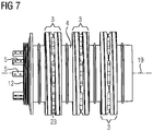
- FIG 6 shows a slip ring unit with three individual slip rings 3 which are arranged axially one behind the other and are separated from one another by insulation 4. Each slip ring 3 is to proceed for an electrical phase U or V or M. At one axial end of this arrangement there is a support ring 12 from which contact points 5 protrude axially parallel and which allow an electrical connection of a winding system 17 of a rotor 16.
- FIG 7 shows the slip ring system 3 according to FIG FIG 6 .
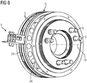
- FIG 8 shows a single slip ring 3, for example phase U of a slip ring unit with the elements mentioned above, such as contact points 5, support ring 12, radial cooling openings 23 and axial cooling openings 24. It is also shown there in principle how a brush holder 1 can be arranged on slip ring 3.
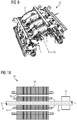
- FIG 9 shows a brush bridge in which four carrier segments 2 are arranged axially one behind the other, with, for example, three carrier segments 2 each assigned to an electrical phase U, V, M and one carrier segment 2 having brushes 8 for grounding.
- FIG 10 shows a basic illustration of the arrangement of a slip ring system 13 on a shaft 18, the slip rings 3 rotating about the axis 19 just like the rotor 16.
- the slip ring system 13 is positioned on the end face of the rotor 16.
- a slip ring system 13 has a brush bridge with carrier segments 2 and a slip ring unit with slip rings 3.
- a carrier segment 2 has one or more brush holders 1, each of which can be assigned to a slip ring 3.
- Each brush holder 1 has one or more brush pockets 7 in which the brushes 8 are positioned.
- the brushes 8 are pressed onto the slip ring 3 by a device not shown in detail in order to ensure proper contact. Furthermore, the brushes 8 are monitored with regard to their wear by a corresponding device.
- the slip ring system 13 has contact points 5, support ring 12, radial cooling openings 23 and axial cooling openings 24.
- cooler ambient air is preferably sucked in by fans and distributed in slip ring system 13 by further fans and / or guide devices, in particular to the heat sources.
- the now in the slip ring system 13 on the brush pockets 7, the Brush holders 1 and / or the brushes 8 heated air is passed from the slip ring space into the environment.
- the air flow is generated by suction and / or pressure fans, which are designed as axial or radial fans and are arranged on or in the slip ring space.
- Filter mats at the entrance and / or exit can filter the polluted air.
- the internal cooling circuit recooled in an intercooler is distributed by fans and / or guide devices, in particular to the heat sources within the closed housing of the slip ring system 13.
- the air that is now heated in the slip ring system 13 on the brush pockets 7, the brush holders 1 and / or the brushes 8 is passed out of the slip ring space into the intercooler (not shown in detail).
- This air flow is generated by suction and / or pressure fans, which are designed as axial or radial fans and are arranged within the housing of the slip ring system 13.
- Such compact slip ring systems 13 are particularly suitable for dynamoelectric machines 14 with a comparatively high output in the MW range.
- These machines 14 are particularly suitable as generators, in particular double-fed asynchronous machines for wind turbines, since the space available in a nacelle of a wind turbine is comparatively tight, and nevertheless comparatively large powers are to be transmitted in the generator.
Landscapes
- Engineering & Computer Science (AREA)
- Power Engineering (AREA)
- Life Sciences & Earth Sciences (AREA)
- Sustainable Development (AREA)
- Sustainable Energy (AREA)
- Physics & Mathematics (AREA)
- Thermal Sciences (AREA)
- Chemical & Material Sciences (AREA)
- Combustion & Propulsion (AREA)
- Mechanical Engineering (AREA)
- General Engineering & Computer Science (AREA)
- Motor Or Generator Cooling System (AREA)
- Motor Or Generator Current Collectors (AREA)
Abstract
Die Erfindung betrifft eine Bürstenhalterung (1) eines Schleifringsystems (13), einer elektrisch erregten dynamoelektrischen Maschine (14), wobei die Bürstenhalterung (1) Mittel zur Kühlung von Bürsten (8) in der Bürstenhalterung (1) und/oder der Bürstenhalterung (1) vorsieht.The invention relates to a brush holder (1) of a slip ring system (13), an electrically excited dynamo-electric machine (14), the brush holder (1) means for cooling brushes (8) in the brush holder (1) and / or the brush holder (1 ) provides.
Description
Die Erfindung betrifft eine Bürstenhalterung eines Schleifringsystems einer dynamoelektrischen erregten Maschine, ein Trägersegment mit derartigen Bürstenhalterungen, ein Schleifringsystem mit derartigen Trägersegmenten, ein Belüftungssystem eines Schleifringsystems und eine dynamoelektrische Maschine.The invention relates to a brush holder of a slip ring system of a dynamoelectric excited machine, a carrier segment with such brush holders, a slip ring system with such carrier segments, a ventilation system of a slip ring system and a dynamoelectric machine.
Schleifringsysteme dienen dazu in den rotierenden Teil einer dynamoelektrischen Maschine, also den Läufer, eine elektrische Erregung einzubringen. Durch immer höhere Leistungen der dynamoelektrischen Maschine, beispielsweise Generatoren von Windkraftanlagen werden die dafür erforderlichen übertragbaren elektrischen Leistungen immer höher. Dies führt zu einer zusätzlichen Erwärmung der Schleifringsysteme, deren Entwärmung aufgrund einer zusätzlichen Kosten- und Bauraumoptimierung dieser Schleifringsysteme und deren Komponenten immer schwieriger wird. Durch die nunmehr bei kompakterer Ausführung anzustrebenden höheren Strombelastungen des Schleifringsystems steigen die Temperaturen, insbesondere der Bürsten und der Bürstenhalter erheblich an. Durch übermäßige Temperaturerhöhung entstehen Schäden an dem Schleifringsystem und auch an den Bürsten.Slip ring systems are used to introduce electrical excitation into the rotating part of a dynamo-electric machine, i.e. the rotor. As the performance of the dynamo-electric machine continues to increase, for example, the generators of wind power plants, the electrical power that can be transmitted becomes higher and higher. This leads to additional heating of the slip ring systems, the cooling of which is becoming increasingly difficult due to additional cost and space optimization of these slip ring systems and their components. As a result of the higher current loads of the slip ring system now to be aimed for in a more compact design, the temperatures, in particular of the brushes and the brush holders, rise considerably. Excessive temperature increases cause damage to the slip ring system and also to the brushes.
Um den steigenden Temperaturen entgegenzutreten, werden ab einer bestimmten Baugröße der dynamoelektrischen Maschine Schleifringkörper mit größeren Außendurchmessern eingesetzt. Dazu werden auch die verwendeten Bürstenhalterungen, die auch als Bürstenbrücken bezeichnet werden, dementsprechend größer dimensioniert. Jedoch nimmt dadurch der Arbeitsbereich des Schleifringsystems wesentlich mehr Raum ein. Durch Vergrößern des Schleifringsystems, wie Schleifringgehäuse und deren Komponenten werden höhere Materialkosten verursacht. Des Weiteren führt diese leistungsbedingte Vergrößerung auch zu einer ungewollten Vergrößerung der Außenabmessung der dynamoelektrischen Maschine.To counter the rising temperatures, slip ring bodies with larger outer diameters are used from a certain size of dynamoelectric machine. For this purpose, the brush holders used, which are also referred to as brush bridges, are dimensioned correspondingly larger. However, this means that the working area of the slip ring system takes up considerably more space. Increasing the size of the slip ring system, such as slip ring housings and their components, results in higher material costs. Furthermore, this performance-related increase also leads to a unwanted enlargement of the external dimensions of the dynamo-electric machine.
Ausgehend davon liegt der Erfindung die Aufgabe zugrunde, ein Schleifringsystem zu schaffen, das auch bei einer vergleichsweise kompakten Ausführung des Schleifringsystems die maximal zulässigen Temperaturen des Schleifringsystems und deren Komponenten nicht überschreitet.Based on this, the invention is based on the object of creating a slip ring system which, even with a comparatively compact design of the slip ring system, does not exceed the maximum permissible temperatures of the slip ring system and its components.
Die Lösung der gestellten Aufgabe gelingt durch eine Bürstenhalterung eines Schleifringsystems, einer elektrisch erregten dynamoelektrischen Maschine, wobei die Bürstenhalterung Mittel zur Kühlung von Bürsten in der Bürstenhalterung und/oder der Bürstenhalterung vorsieht.The problem is solved by a brush holder of a slip ring system, an electrically excited dynamo-electric machine, the brush holder providing means for cooling brushes in the brush holder and / or the brush holder.
Durch die erfindungsgemäße Bürstenhalterung kann nunmehr jede Bürste in der Bürstenhalterung vergleichsweise gut gekühlt werden, sodass die übertragbare Leistung in einen Läufer einer dynamoelektrischen Maschine gesteigert werden kann.With the brush holder according to the invention, each brush in the brush holder can now be cooled comparatively well, so that the power that can be transmitted to a rotor of a dynamo-electric machine can be increased.
Die Lösung der gestellten Aufgabe gelingt ebenso durch Trägersegment mit einer oder mehreren erfindungsgemäßen Bürstenhalterungen.The problem posed is also achieved by means of a carrier segment with one or more brush holders according to the invention.
Dies trägt zu einer Vergleichmäßigung des Leistungsflusses bzw. des Stromes über die Bürsten einer elektrischen Phase eines Schleifringsystems bei.This helps to make the power flow or the current across the brushes of an electrical phase of a slip ring system more uniform.
Die Lösung der gestellten Aufgabe gelingt auch durch Schleifringsystem mit einem oder mehrerer erfindungsgemäßer Trägersegmente. Durch die verbesserte Kühlleistung von Bürsten und/oder Bürstenhalterung und damit eines Trägersystems wird auch das Schleifringsystem thermisch nahezu gleichmäßig belastet und ausreichend gekühlt, so dass eine kompakte Bauweise des Schleifringsystems vorliegt.The problem posed is also achieved by means of a slip ring system with one or more carrier segments according to the invention. Due to the improved cooling performance of the brushes and / or brush holder and thus of a carrier system, the slip ring system is also thermally almost uniformly loaded and adequately cooled, so that the slip ring system has a compact design.
Die Lösung der gestellten Aufgabe gelingt auch durch Belüftungssystem mit einem erfindungsgemäßen Schleifringsystem. Das Belüftungssystem führt Luft innerhalb des Schleifringsystems, das geschlossen oder offen ausgeführt ist, derart, dass Bürstenhalterungen, und/oder Bürstentaschen und/oder Bürsten kühlbar sind. Die gelingt indem der erforderliche Kühlluftstrom, erzeugt durch Radial- und/oder Axiallüfter innerhalb oder an dem Schleifringsystem vorgesehen sind.The problem posed is also achieved by a ventilation system with a slip ring system according to the invention. The ventilation system guides air within the slip ring system, which is designed to be closed or open, in such a way that brush holders and / or brush pockets and / or brushes can be cooled. This is achieved in that the required flow of cooling air, generated by radial and / or axial fans, is provided inside or on the slip ring system.
Die Lösung der gestellten Aufgabe gelingt auch durch eine dynamoelektrische Maschine, insbesondere Generator einer Windkraftanlage mit einem erfindungsgemäßen Belüftungssystem oder einer erfindungsgemäßen Schleifringsystem.The problem posed is also achieved by a dynamoelectric machine, in particular a generator of a wind power plant with a ventilation system according to the invention or a slip ring system according to the invention.
Durch Vergrößern der Oberfläche der Bürstentaschen mittels Rippen, Nadeln oder Noppen an der Oberfläche der Bürstentaschen, als auch gegebenenfalls Ausnehmungen an den Bürstentaschen, wird die Kühloberfläche der Bürstentaschen und/oder der überströmten Fläche der Bürsten durch einen Kühlluftstrom vergrößert. Die Rippen können dabei als Rechteckrippen, Dreieckrippen, Trapezrippen, konkave oder konvexe parabolische Rippen ausgeführt sein, ebenso wie die Nadeln als zylindrische- konische, konkave, parabolische- oder konvexe parabolische Nadeln oder Noppen ausgeführt sein können.By enlarging the surface of the brush pockets by means of ribs, needles or knobs on the surface of the brush pockets, as well as possibly recesses on the brush pockets, the cooling surface of the brush pockets and / or the overflow area of the brushes is enlarged by a cooling air flow. The ribs can be designed as rectangular ribs, triangular ribs, trapezoidal ribs, concave or convex parabolic ribs, just as the needles can be designed as cylindrical-conical, concave, parabolic or convex parabolic needles or knobs.
Durch zumindest einen innerhalb des Schleifringsystems angeordneten Lüfter wird Luft an den Bürstentasche und Bürstenhalterungen vorbeigeführt, die oberflächenvergrößernde Strukturen aufweisen.At least one fan arranged within the slip ring system guides air past the brush pocket and brush holders, which have surface-enlarging structures.
Vorteilhafterweise können dabei dementsprechende Lüfter eingesetzt werden, die einen Radialluftstrom und/oder einen in Umfangsrichtung verlaufenden Kühlluftstrom generieren. Dies kann unterstützt werden, in dem die Noppen, Nadeln oder Rippen dementsprechend in Strömungsrichtung eines generierten Kühlluftstroms angeordnet werden.Corresponding fans can advantageously be used, which generate a radial air flow and / or a cooling air flow running in the circumferential direction. This can be supported in that the knobs, needles or ribs are arranged accordingly in the flow direction of a generated cooling air flow.
Durch die Reduzierung der Betriebstemperaturen im Schleifringsystem werden dadurch niedrigere Temperaturen geschaffen, die somit auch vergleichsweise geringere Bauabmessungen eines Schleifringsystems und deren angrenzenden Komponenten gestatten. Des Weiteren kann die übertragene Leistung von den Bürsten auf den jeweiligen Schleifring auch mit vergleichsweise weniger Bürsten pro elektrische Phase betrieben werden, ohne dass dabei die Bürsten Kühlungsprobleme aufweisen.By reducing the operating temperatures in the slip ring system, lower temperatures are created, which means that the overall dimensions of a Allow slip ring systems and their adjacent components. Furthermore, the power transferred from the brushes to the respective slip ring can also be operated with comparatively fewer brushes per electrical phase, without the brushes having cooling problems.
Es sind somit höhere Leistungsstufen der gesamten Schleifringsysteme und damit der dynamoelektrischen Maschine möglich.Thus, higher performance levels of the entire slip ring systems and thus of the dynamo-electric machine are possible.
Eine Belüftung des Schleifringsystems ist somit durch eine Durchzugsbelüftung, als auch oder ergänzend durch eine Fremdbelüftung möglich. Der Kühlluftstrom oder die Kühlluftströme werden durch Lüfter in und/oder an dem Schleifringsystem generiert.A ventilation of the slip ring system is thus possible through a draft ventilation, as well as or in addition through an external ventilation. The cooling air flow or the cooling air flows are generated by fans in and / or on the slip ring system.
Die Außenluft, die als kühlere Luft über die Kühlöffnungen in das Schleifringsystem gesaugt wird, wird innerhalb des Schleifringsystems über Kühlluftführungen bzw. Leitvorrichtungen unter anderem direkt an die Bürstentasche, die Bürstenhalterung und/oder die Bürsten geführt. Da dies die kritischen Wärmequellen sind, werden diese nun direkt mit dem sogenannten Kaltluftstrom direkt gekühlt.The outside air, which is sucked into the slip ring system as cooler air via the cooling openings, is guided within the slip ring system via cooling air ducts or guiding devices, among other things, directly to the brush pocket, the brush holder and / or the brushes. Since these are the critical heat sources, they are now directly cooled with the so-called cold air flow.
Damit können in dem Schleifringsystem vorhandene Lüfter, wie z.B. Radiallüfter unterstützt werden.This means that fans present in the slip ring system, e.g. Radial fans are supported.
Bei einem durchzugsbelüfteten Schleifringsystem wird kühlere Umgebungsluft angesaugt und im Schleifringsystem durch Lüfter und/oder Leitvorrichtungen, insbesondere an die Wärmequellen verteilt. Die nun im Schleifringsystem an den Bürstentaschen, den Bürstenhalterungen und/oder den Bürsten erwärmte Luft wird aus dem Schleifringraum in die Umgebung abgeführt. Die Luftströmung wird dabei von Saug- und/oder Drucklüftern generiert, die als Axial- oder Radiallüfter ausgeführt sind.In a through-ventilated slip ring system, cooler ambient air is sucked in and distributed in the slip ring system by fans and / or guide devices, in particular to the heat sources. The air that is now heated in the slip ring system on the brush pockets, the brush holders and / or the brushes is discharged from the slip ring space into the environment. The air flow is generated by suction and / or pressure fans that are designed as axial or radial fans.
Filtermatten am Zugang und/oder am Abgang können dabei die verschmutzte Luft filtern.Filter mats at the entrance and / or exit can filter the polluted air.
Bei einem geschlossenen Schleifringsystem wird der in einem Zwischenkühler rückgekühlte Innenkühlkreislauf durch Lüfter und/oder Leitvorrichtungen, insbesondere an die Wärmequellen innerhalb des geschlossenen Gehäuses des Schleifringsystems verteilt. Die nun im Schleifringsystem an den Bürstentaschen, den Bürstenhalterungen und/oder den Bürsten erwärmte Luft wird aus dem Schleifringraum in den Zwischenkühler geleitet. Diese Luftströmung wird dabei von Saug- und/oder Drucklüftern generiert, die als Axial- oder Radiallüfter ausgeführt sind und innerhalb des Gehäuses des Schleifringsystems angeordnet sind.In the case of a closed slip ring system, the internal cooling circuit recooled in an intercooler is distributed by fans and / or guide devices, in particular to the heat sources within the closed housing of the slip ring system. The air that is now heated in the slip ring system on the brush pockets, the brush holders and / or the brushes is passed from the slip ring space into the intercooler. This air flow is generated by suction and / or pressure fans, which are designed as axial or radial fans and are arranged within the housing of the slip ring system.
Die Erfindung sowie weitere vorteilhafte Ausgestaltungen der Erfindung werden anhand prinzipiell dargestellter Ausführungsbeispiele näher erläutert. Darin zeigen:
- FIG 1
- eine Bürstenhalterung,
- FIG 2 bis FIG 5
- jeweils ein Trägersegment mit Bürstenhaltung,
- FIG 6 bis FIG 8
- jeweils einen Schleifring,
- FIG 9
- eine Bürstenbrücke und
- FIG 10
- eine prinzipiell dargestellte dynamoelektrische Maschine mit Schleifringsystem.
- FIG 1
- a brush holder,
- FIG. 2 to FIG. 5
- one carrier segment each with a brush holder,
- FIG. 6 to FIG. 8
- one slip ring each,
- FIG 9
- a brush bridge and
- FIG 10
- a dynamo-electric machine shown in principle with slip ring system.
Es sind grundsätzlich auch Ausführungen der Bürstentaschen 7 oder Bürstenhalterungen 1 möglich, bei denen Ausnehmungen 11 und oberflächenvergrößernde Strukturen, wie Rippen 9 realisiert sind.In principle, designs of the brush pockets 7 or
Ein Schleifringsystems 13 weist eine Bürstenbrücke, mit Trägersegmenten 2 und eine Schleifringeinheit mit Schleifringen 3 auf. Ein Trägersegment 2 weist eine oder mehrere Bürstenhalterungen 1 auf, die jeweils einem Schleifring 3 zuzuordnen sind. Jede Bürstenhalterung 1 weist eine oder mehrere Bürstentaschen 7 auf, in denen die Bürsten 8 positioniert sind. Die Bürsten 8 werden durch nicht näher dargestellte Vorrichtung auf den Schleifring 3 gedrückt, um einen ordnungsgemäßen Kontakt zu gewährleisten. Des Weiteren werden die Bürsten 8 durch dementsprechende Einrichtung bezüglich ihres Verschleißes überwacht. Des Weiteren weist das Schleifringsystem 13 Kontaktstellen 5, Stützring 12, radialen Kühlöffnungen 23 und axialen Kühlöffnungen 24 auf.A
Bei einem durchzugsbelüfteten Schleifringsystem 13 wird vorzugsweise kühlere Umgebungsluft durch Lüfter angesaugt und im Schleifringsystem 13 durch ggf. weitere Lüfter und/oder Leitvorrichtungen, insbesondere an die Wärmequellen verteilt. Die nun im Schleifringsystem 13 an den Bürstentaschen 7, den Bürstenhalterungen 1 und/oder den Bürsten 8 erwärmte Luft wird aus dem Schleifringraum in die Umgebung geleitet. Die Luftströmung wird dabei von Saug- und/oder Drucklüftern generiert, die als Axial- oder Radiallüfter ausgeführt sind und am oder im Schleifringraum angeordnet sind.In the case of a through-ventilated
Filtermatten am Zugang und/oder am Abgang können dabei die verschmutzte Luft filtern.Filter mats at the entrance and / or exit can filter the polluted air.
Bei einem geschlossenen Schleifringsystem 13 wird der in einem Zwischenkühler rückgekühlte Innenkühlkreislauf durch Lüfter und/oder Leitvorrichtungen, insbesondere an die Wärmequellen innerhalb des geschlossenen Gehäuses des Schleifringsystems 13 verteilt. Die nun im Schleifringsystem 13 an den Bürstentaschen 7, den Bürstenhalterungen 1 und/oder den Bürsten 8 erwärmte Luft wird aus dem Schleifringraum, in den nicht näher dargestellten Zwischenkühler geleitet. Diese Luftströmung wird dabei von Saug- und/oder Drucklüftern generiert, die als Axial- oder Radiallüfter ausgeführt sind und innerhalb des Gehäuses des Schleifringsystems 13 angeordnet sind.In the case of a closed
Derartige kompakte Schleifringsysteme 13 eignen sich vor allem für dynamoelektrischen Maschinen 14 mit vergleichsweise hoher Leistung im MW-Bereich. Dabei sind diese Maschinen 14 besonders als Generatoren, insbesondere doppelt gespeiste Asynchronmaschinen von Windkraftanlagen geeignet, da der vorhandene Bauraum in einer Gondel einer Windkraftanlage vergleichsweise knapp bemessen ist, und trotzdem vergleichsweise große Leistungen im Generator übertragen werden sollen.Such compact
Claims (9)
Priority Applications (7)
| Application Number | Priority Date | Filing Date | Title |
|---|---|---|---|
| EP19177085.8A EP3745544A1 (en) | 2019-05-28 | 2019-05-28 | Slip ring system with improved cooling |
| BR112021020887A BR112021020887A2 (en) | 2019-05-28 | 2020-04-03 | Ventilation system of a slip ring system, and, dynamoelectric machine |
| US17/613,352 US11916467B2 (en) | 2019-05-28 | 2020-04-03 | Slip ring system with improved cooling |
| CA3138621A CA3138621A1 (en) | 2019-05-28 | 2020-04-03 | Slip ring system with imrpoved cooling |
| PCT/EP2020/059546 WO2020239301A1 (en) | 2019-05-28 | 2020-04-03 | Slip ring assembly with improved cooling |
| CN202080039385.6A CN113892215B (en) | 2019-05-28 | 2020-04-03 | Slip ring system with improved cooling |
| EP20718258.5A EP3977572A1 (en) | 2019-05-28 | 2020-04-03 | Slip ring assembly with improved cooling |
Applications Claiming Priority (1)
| Application Number | Priority Date | Filing Date | Title |
|---|---|---|---|
| EP19177085.8A EP3745544A1 (en) | 2019-05-28 | 2019-05-28 | Slip ring system with improved cooling |
Publications (1)
| Publication Number | Publication Date |
|---|---|
| EP3745544A1 true EP3745544A1 (en) | 2020-12-02 |
Family
ID=66676261
Family Applications (2)
| Application Number | Title | Priority Date | Filing Date |
|---|---|---|---|
| EP19177085.8A Withdrawn EP3745544A1 (en) | 2019-05-28 | 2019-05-28 | Slip ring system with improved cooling |
| EP20718258.5A Pending EP3977572A1 (en) | 2019-05-28 | 2020-04-03 | Slip ring assembly with improved cooling |
Family Applications After (1)
| Application Number | Title | Priority Date | Filing Date |
|---|---|---|---|
| EP20718258.5A Pending EP3977572A1 (en) | 2019-05-28 | 2020-04-03 | Slip ring assembly with improved cooling |
Country Status (6)
| Country | Link |
|---|---|
| US (1) | US11916467B2 (en) |
| EP (2) | EP3745544A1 (en) |
| CN (1) | CN113892215B (en) |
| BR (1) | BR112021020887A2 (en) |
| CA (1) | CA3138621A1 (en) |
| WO (1) | WO2020239301A1 (en) |
Cited By (3)
| Publication number | Priority date | Publication date | Assignee | Title |
|---|---|---|---|---|
| US20210167670A1 (en) * | 2018-07-27 | 2021-06-03 | Flender Gmbh | Holding device for a slip ring unit, slip ring bridge, slip ring unit, electric machine, and wind turbine |
| CN113708570A (en) * | 2021-08-18 | 2021-11-26 | 西安中车永电捷力风能有限公司 | Double-fed aerogenerator sliding ring room cooling structure |
| US20220224204A1 (en) * | 2019-05-28 | 2022-07-14 | Flender Gmbh | Slip ring system with improved cooling |
Citations (3)
| Publication number | Priority date | Publication date | Assignee | Title |
|---|---|---|---|---|
| JPS5028606A (en) * | 1973-07-20 | 1975-03-24 | ||
| EP3291423A1 (en) * | 2016-08-29 | 2018-03-07 | Siemens Aktiengesellschaft | Slip ring assembly |
| US20180166844A1 (en) * | 2015-05-29 | 2018-06-14 | Siemens Aktiengesellschaft | Arrangement for guiding and/or holding electrically conductive sliding contact elements |
Family Cites Families (21)
| Publication number | Priority date | Publication date | Assignee | Title |
|---|---|---|---|---|
| CH571283A5 (en) * | 1974-04-17 | 1975-12-31 | Bbc Brown Boveri & Cie | |
| US4137474A (en) * | 1974-06-04 | 1979-01-30 | Kraftwerk Union Aktiengesellschaft | Gas-cooled slip ring for electrical machines |
| DE2848410A1 (en) * | 1978-11-08 | 1980-05-29 | Bosch Gmbh Robert | COVER FOR ELECTRICAL MACHINES |
| JP3430027B2 (en) * | 1998-09-04 | 2003-07-28 | 三菱電機株式会社 | AC generator for vehicles |
| JP4106852B2 (en) * | 2000-04-14 | 2008-06-25 | 株式会社デンソー | AC generator for vehicles |
| GB2367193A (en) * | 2000-09-20 | 2002-03-27 | Johnson Electric Sa | Cooling brushes in a miniature electric motor |
| DE10154866A1 (en) * | 2001-11-08 | 2003-05-28 | Bosch Gmbh Robert | Electrical machine, preferably three-phase generator for motor vehicles |
| JP4471126B2 (en) * | 2006-09-07 | 2010-06-02 | 株式会社デンソー | Vehicle alternator |
| US7843080B2 (en) * | 2009-05-11 | 2010-11-30 | General Electric Company | Cooling system and wind turbine incorporating same |
| JP4810589B2 (en) * | 2009-05-28 | 2011-11-09 | 三菱電機株式会社 | Rotating electric machine |
| US9479029B2 (en) * | 2011-06-07 | 2016-10-25 | Mitsubishi Electric Corporation | Electric rotating machine |
| CN103609007A (en) * | 2011-07-28 | 2014-02-26 | 三菱电机株式会社 | Dynamo-electric machine |
| US10069374B2 (en) * | 2011-10-25 | 2018-09-04 | Mitsubishi Electric Corporation | Rotary electric machine having an heat sink with semiconductor modules attached |
| JP5634618B2 (en) * | 2011-11-09 | 2014-12-03 | 三菱電機株式会社 | Rotating electric machine |
| WO2013069105A1 (en) * | 2011-11-09 | 2013-05-16 | 三菱電機株式会社 | Rotary electric machine |
| JP5542977B1 (en) * | 2013-01-24 | 2014-07-09 | 三菱電機株式会社 | Rotating electric machine |
| JP5721794B2 (en) * | 2013-08-26 | 2015-05-20 | 三菱電機株式会社 | Controller-integrated rotating electrical machine |
| CN207732237U (en) * | 2017-12-29 | 2018-08-14 | 江苏民威电碳科技有限公司 | A kind of brush that commutating character is excellent |
| CN208046397U (en) * | 2018-02-13 | 2018-11-02 | 西门子公司 | Slip ring structure and slip ring motor |
| EP3537577A1 (en) * | 2018-03-08 | 2019-09-11 | Siemens Aktiengesellschaft | Slip ring unit with active cooling system |
| EP3745544A1 (en) * | 2019-05-28 | 2020-12-02 | Siemens Aktiengesellschaft | Slip ring system with improved cooling |
-
2019
- 2019-05-28 EP EP19177085.8A patent/EP3745544A1/en not_active Withdrawn
-
2020
- 2020-04-03 US US17/613,352 patent/US11916467B2/en active Active
- 2020-04-03 CN CN202080039385.6A patent/CN113892215B/en active Active
- 2020-04-03 EP EP20718258.5A patent/EP3977572A1/en active Pending
- 2020-04-03 BR BR112021020887A patent/BR112021020887A2/en unknown
- 2020-04-03 CA CA3138621A patent/CA3138621A1/en active Pending
- 2020-04-03 WO PCT/EP2020/059546 patent/WO2020239301A1/en active Search and Examination
Patent Citations (3)
| Publication number | Priority date | Publication date | Assignee | Title |
|---|---|---|---|---|
| JPS5028606A (en) * | 1973-07-20 | 1975-03-24 | ||
| US20180166844A1 (en) * | 2015-05-29 | 2018-06-14 | Siemens Aktiengesellschaft | Arrangement for guiding and/or holding electrically conductive sliding contact elements |
| EP3291423A1 (en) * | 2016-08-29 | 2018-03-07 | Siemens Aktiengesellschaft | Slip ring assembly |
Cited By (5)
| Publication number | Priority date | Publication date | Assignee | Title |
|---|---|---|---|---|
| US20210167670A1 (en) * | 2018-07-27 | 2021-06-03 | Flender Gmbh | Holding device for a slip ring unit, slip ring bridge, slip ring unit, electric machine, and wind turbine |
| US11664709B2 (en) * | 2018-07-27 | 2023-05-30 | Flender Gmbh | Holding apparatus for a slip ring unit, slip ring bridge, slip ring unit, electric machine, and wind turbine |
| US20220224204A1 (en) * | 2019-05-28 | 2022-07-14 | Flender Gmbh | Slip ring system with improved cooling |
| US11916467B2 (en) * | 2019-05-28 | 2024-02-27 | Flender Gmbh | Slip ring system with improved cooling |
| CN113708570A (en) * | 2021-08-18 | 2021-11-26 | 西安中车永电捷力风能有限公司 | Double-fed aerogenerator sliding ring room cooling structure |
Also Published As
| Publication number | Publication date |
|---|---|
| WO2020239301A1 (en) | 2020-12-03 |
| CN113892215A (en) | 2022-01-04 |
| US20220224204A1 (en) | 2022-07-14 |
| CA3138621A1 (en) | 2020-12-03 |
| US11916467B2 (en) | 2024-02-27 |
| CN113892215B (en) | 2023-12-08 |
| EP3977572A1 (en) | 2022-04-06 |
| BR112021020887A2 (en) | 2021-12-21 |
Similar Documents
| Publication | Publication Date | Title |
|---|---|---|
| EP3745544A1 (en) | Slip ring system with improved cooling | |
| EP3476012B1 (en) | Slip ring unit with fan insulation segment | |
| DE102011087602B4 (en) | Electric machine | |
| DE10355385A1 (en) | Sealing device for the ventilation system of an electrical generator | |
| DE102010029986A1 (en) | Dynamoelectric machine with air-liquid cooling | |
| EP2930827B1 (en) | Electric machine with flow cooling | |
| DE602004011600T2 (en) | Electric engine | |
| EP3033825B1 (en) | Device for deflecting at least one portion of a cooling fluid flowing axially in a space between a rotor and a stator of a rotating electric machine | |
| DE10307813B4 (en) | Electric machine | |
| DE102010001437B4 (en) | Dynamo-electric machine with a slip ring rotor and a closed slip ring arrangement | |
| DE2007194A1 (en) | Cooling gas routing in electrical machines | |
| EP1249578A1 (en) | Cooling of a gas turbine | |
| DE102008035159A1 (en) | Cooling air flow path for belt-driven power generator for vehicles | |
| DE102014223527A1 (en) | Cooling of an axial end portion of a stator of a rotating electrical machine | |
| EP0522210B1 (en) | Cooling system of a rotating electrical machine and electrical machine for carrying out such a system | |
| EP2961009B1 (en) | Wind power generator with a slip ring assembly | |
| EP3732772B1 (en) | Slip ring unit with active cooling system | |
| EP2887509B1 (en) | Electrical contacting device for an electric machine | |
| DE102015219669A1 (en) | Electric machine with a cooling device | |
| EP2887510B1 (en) | Electrical contacting device for an electric machine | |
| EP4030595A1 (en) | Dynamoelectric machine with slip ring system cooling | |
| EP0985262A1 (en) | Liquid-cooled electric machine | |
| EP3599679A1 (en) | Holding device for a slip ring unit, slip ring bridge, slip ring unit, electric machine and wind power plant | |
| DE102014102999A1 (en) | Turbine shroud cooling system | |
| DE102013203068B4 (en) | Electric machine with cooled junction box and cooling method |
Legal Events
| Date | Code | Title | Description |
|---|---|---|---|
| PUAI | Public reference made under article 153(3) epc to a published international application that has entered the european phase |
Free format text: ORIGINAL CODE: 0009012 |
|
| STAA | Information on the status of an ep patent application or granted ep patent |
Free format text: STATUS: THE APPLICATION HAS BEEN PUBLISHED |
|
| AK | Designated contracting states |
Kind code of ref document: A1 Designated state(s): AL AT BE BG CH CY CZ DE DK EE ES FI FR GB GR HR HU IE IS IT LI LT LU LV MC MK MT NL NO PL PT RO RS SE SI SK SM TR |
|
| AX | Request for extension of the european patent |
Extension state: BA ME |
|
| STAA | Information on the status of an ep patent application or granted ep patent |
Free format text: STATUS: THE APPLICATION IS DEEMED TO BE WITHDRAWN |
|
| 18D | Application deemed to be withdrawn |
Effective date: 20210603 |