EP3745076B1 - Boîte collectrice de tuyau et échangeur de chaleur - Google Patents
Boîte collectrice de tuyau et échangeur de chaleur Download PDFInfo
- Publication number
- EP3745076B1 EP3745076B1 EP19807116.9A EP19807116A EP3745076B1 EP 3745076 B1 EP3745076 B1 EP 3745076B1 EP 19807116 A EP19807116 A EP 19807116A EP 3745076 B1 EP3745076 B1 EP 3745076B1
- Authority
- EP
- European Patent Office
- Prior art keywords
- header
- header box
- plate
- hole
- heat exchange
- Prior art date
- Legal status (The legal status is an assumption and is not a legal conclusion. Google has not performed a legal analysis and makes no representation as to the accuracy of the status listed.)
- Active
Links
- 230000017525 heat dissipation Effects 0.000 claims description 34
- 238000005192 partition Methods 0.000 claims description 28
- 238000004891 communication Methods 0.000 claims description 7
- 239000012530 fluid Substances 0.000 claims description 3
- 238000003466 welding Methods 0.000 description 21
- 230000009286 beneficial effect Effects 0.000 description 12
- 230000001965 increasing effect Effects 0.000 description 8
- 238000009434 installation Methods 0.000 description 8
- 238000000034 method Methods 0.000 description 6
- 230000002093 peripheral effect Effects 0.000 description 6
- 238000012545 processing Methods 0.000 description 6
- 229910000679 solder Inorganic materials 0.000 description 6
- 238000009826 distribution Methods 0.000 description 3
- 230000000694 effects Effects 0.000 description 3
- 238000003780 insertion Methods 0.000 description 3
- 230000037431 insertion Effects 0.000 description 3
- 239000003507 refrigerant Substances 0.000 description 3
- 230000002787 reinforcement Effects 0.000 description 3
- 238000004378 air conditioning Methods 0.000 description 2
- 230000000903 blocking effect Effects 0.000 description 2
- 238000004519 manufacturing process Methods 0.000 description 2
- 238000005057 refrigeration Methods 0.000 description 2
- 238000005219 brazing Methods 0.000 description 1
- 230000000295 complement effect Effects 0.000 description 1
- 239000000110 cooling liquid Substances 0.000 description 1
- 230000007423 decrease Effects 0.000 description 1
- 230000002708 enhancing effect Effects 0.000 description 1
- 239000000463 material Substances 0.000 description 1
- 230000008646 thermal stress Effects 0.000 description 1
- 238000012546 transfer Methods 0.000 description 1
Images


Classifications
-
- F—MECHANICAL ENGINEERING; LIGHTING; HEATING; WEAPONS; BLASTING
- F28—HEAT EXCHANGE IN GENERAL
- F28F—DETAILS OF HEAT-EXCHANGE AND HEAT-TRANSFER APPARATUS, OF GENERAL APPLICATION
- F28F9/00—Casings; Header boxes; Auxiliary supports for elements; Auxiliary members within casings
- F28F9/02—Header boxes; End plates
- F28F9/0202—Header boxes having their inner space divided by partitions
- F28F9/0204—Header boxes having their inner space divided by partitions for elongated header box, e.g. with transversal and longitudinal partitions
- F28F9/0207—Header boxes having their inner space divided by partitions for elongated header box, e.g. with transversal and longitudinal partitions the longitudinal or transversal partitions being separate elements attached to header boxes
-
- F—MECHANICAL ENGINEERING; LIGHTING; HEATING; WEAPONS; BLASTING
- F28—HEAT EXCHANGE IN GENERAL
- F28D—HEAT-EXCHANGE APPARATUS, NOT PROVIDED FOR IN ANOTHER SUBCLASS, IN WHICH THE HEAT-EXCHANGE MEDIA DO NOT COME INTO DIRECT CONTACT
- F28D7/00—Heat-exchange apparatus having stationary tubular conduit assemblies for both heat-exchange media, the media being in contact with different sides of a conduit wall
- F28D7/16—Heat-exchange apparatus having stationary tubular conduit assemblies for both heat-exchange media, the media being in contact with different sides of a conduit wall the conduits being arranged in parallel spaced relation
- F28D7/1684—Heat-exchange apparatus having stationary tubular conduit assemblies for both heat-exchange media, the media being in contact with different sides of a conduit wall the conduits being arranged in parallel spaced relation the conduits having a non-circular cross-section
-
- B—PERFORMING OPERATIONS; TRANSPORTING
- B60—VEHICLES IN GENERAL
- B60H—ARRANGEMENTS OF HEATING, COOLING, VENTILATING OR OTHER AIR-TREATING DEVICES SPECIALLY ADAPTED FOR PASSENGER OR GOODS SPACES OF VEHICLES
- B60H1/00—Heating, cooling or ventilating [HVAC] devices
- B60H1/00321—Heat exchangers for air-conditioning devices
- B60H1/00335—Heat exchangers for air-conditioning devices of the gas-air type
-
- B—PERFORMING OPERATIONS; TRANSPORTING
- B60—VEHICLES IN GENERAL
- B60H—ARRANGEMENTS OF HEATING, COOLING, VENTILATING OR OTHER AIR-TREATING DEVICES SPECIALLY ADAPTED FOR PASSENGER OR GOODS SPACES OF VEHICLES
- B60H1/00—Heating, cooling or ventilating [HVAC] devices
- B60H1/00321—Heat exchangers for air-conditioning devices
- B60H1/00342—Heat exchangers for air-conditioning devices of the liquid-liquid type
-
- F—MECHANICAL ENGINEERING; LIGHTING; HEATING; WEAPONS; BLASTING
- F28—HEAT EXCHANGE IN GENERAL
- F28D—HEAT-EXCHANGE APPARATUS, NOT PROVIDED FOR IN ANOTHER SUBCLASS, IN WHICH THE HEAT-EXCHANGE MEDIA DO NOT COME INTO DIRECT CONTACT
- F28D1/00—Heat-exchange apparatus having stationary conduit assemblies for one heat-exchange medium only, the media being in contact with different sides of the conduit wall, in which the other heat-exchange medium is a large body of fluid, e.g. domestic or motor car radiators
- F28D1/02—Heat-exchange apparatus having stationary conduit assemblies for one heat-exchange medium only, the media being in contact with different sides of the conduit wall, in which the other heat-exchange medium is a large body of fluid, e.g. domestic or motor car radiators with heat-exchange conduits immersed in the body of fluid
- F28D1/04—Heat-exchange apparatus having stationary conduit assemblies for one heat-exchange medium only, the media being in contact with different sides of the conduit wall, in which the other heat-exchange medium is a large body of fluid, e.g. domestic or motor car radiators with heat-exchange conduits immersed in the body of fluid with tubular conduits
- F28D1/053—Heat-exchange apparatus having stationary conduit assemblies for one heat-exchange medium only, the media being in contact with different sides of the conduit wall, in which the other heat-exchange medium is a large body of fluid, e.g. domestic or motor car radiators with heat-exchange conduits immersed in the body of fluid with tubular conduits the conduits being straight
-
- F—MECHANICAL ENGINEERING; LIGHTING; HEATING; WEAPONS; BLASTING
- F28—HEAT EXCHANGE IN GENERAL
- F28D—HEAT-EXCHANGE APPARATUS, NOT PROVIDED FOR IN ANOTHER SUBCLASS, IN WHICH THE HEAT-EXCHANGE MEDIA DO NOT COME INTO DIRECT CONTACT
- F28D9/00—Heat-exchange apparatus having stationary plate-like or laminated conduit assemblies for both heat-exchange media, the media being in contact with different sides of a conduit wall
- F28D9/0093—Multi-circuit heat-exchangers, e.g. integrating different heat exchange sections in the same unit or heat-exchangers for more than two fluids
-
- F—MECHANICAL ENGINEERING; LIGHTING; HEATING; WEAPONS; BLASTING
- F28—HEAT EXCHANGE IN GENERAL
- F28F—DETAILS OF HEAT-EXCHANGE AND HEAT-TRANSFER APPARATUS, OF GENERAL APPLICATION
- F28F9/00—Casings; Header boxes; Auxiliary supports for elements; Auxiliary members within casings
- F28F9/02—Header boxes; End plates
- F28F9/0202—Header boxes having their inner space divided by partitions
- F28F9/0204—Header boxes having their inner space divided by partitions for elongated header box, e.g. with transversal and longitudinal partitions
-
- F—MECHANICAL ENGINEERING; LIGHTING; HEATING; WEAPONS; BLASTING
- F28—HEAT EXCHANGE IN GENERAL
- F28F—DETAILS OF HEAT-EXCHANGE AND HEAT-TRANSFER APPARATUS, OF GENERAL APPLICATION
- F28F9/00—Casings; Header boxes; Auxiliary supports for elements; Auxiliary members within casings
- F28F9/02—Header boxes; End plates
- F28F9/0219—Arrangements for sealing end plates into casing or header box; Header box sub-elements
- F28F9/0221—Header boxes or end plates formed by stacked elements
-
- F—MECHANICAL ENGINEERING; LIGHTING; HEATING; WEAPONS; BLASTING
- F28—HEAT EXCHANGE IN GENERAL
- F28D—HEAT-EXCHANGE APPARATUS, NOT PROVIDED FOR IN ANOTHER SUBCLASS, IN WHICH THE HEAT-EXCHANGE MEDIA DO NOT COME INTO DIRECT CONTACT
- F28D21/00—Heat-exchange apparatus not covered by any of the groups F28D1/00 - F28D20/00
- F28D2021/0019—Other heat exchangers for particular applications; Heat exchange systems not otherwise provided for
- F28D2021/0068—Other heat exchangers for particular applications; Heat exchange systems not otherwise provided for for refrigerant cycles
-
- F—MECHANICAL ENGINEERING; LIGHTING; HEATING; WEAPONS; BLASTING
- F28—HEAT EXCHANGE IN GENERAL
- F28D—HEAT-EXCHANGE APPARATUS, NOT PROVIDED FOR IN ANOTHER SUBCLASS, IN WHICH THE HEAT-EXCHANGE MEDIA DO NOT COME INTO DIRECT CONTACT
- F28D21/00—Heat-exchange apparatus not covered by any of the groups F28D1/00 - F28D20/00
- F28D2021/0019—Other heat exchangers for particular applications; Heat exchange systems not otherwise provided for
- F28D2021/008—Other heat exchangers for particular applications; Heat exchange systems not otherwise provided for for vehicles
- F28D2021/0084—Condensers
-
- F—MECHANICAL ENGINEERING; LIGHTING; HEATING; WEAPONS; BLASTING
- F28—HEAT EXCHANGE IN GENERAL
- F28D—HEAT-EXCHANGE APPARATUS, NOT PROVIDED FOR IN ANOTHER SUBCLASS, IN WHICH THE HEAT-EXCHANGE MEDIA DO NOT COME INTO DIRECT CONTACT
- F28D21/00—Heat-exchange apparatus not covered by any of the groups F28D1/00 - F28D20/00
- F28D2021/0019—Other heat exchangers for particular applications; Heat exchange systems not otherwise provided for
- F28D2021/008—Other heat exchangers for particular applications; Heat exchange systems not otherwise provided for for vehicles
- F28D2021/0085—Evaporators
-
- F—MECHANICAL ENGINEERING; LIGHTING; HEATING; WEAPONS; BLASTING
- F28—HEAT EXCHANGE IN GENERAL
- F28F—DETAILS OF HEAT-EXCHANGE AND HEAT-TRANSFER APPARATUS, OF GENERAL APPLICATION
- F28F9/00—Casings; Header boxes; Auxiliary supports for elements; Auxiliary members within casings
- F28F9/02—Header boxes; End plates
- F28F2009/0285—Other particular headers or end plates
- F28F2009/0297—Side headers, e.g. for radiators having conduits laterally connected to common header
-
- F—MECHANICAL ENGINEERING; LIGHTING; HEATING; WEAPONS; BLASTING
- F28—HEAT EXCHANGE IN GENERAL
- F28F—DETAILS OF HEAT-EXCHANGE AND HEAT-TRANSFER APPARATUS, OF GENERAL APPLICATION
- F28F9/00—Casings; Header boxes; Auxiliary supports for elements; Auxiliary members within casings
- F28F9/02—Header boxes; End plates
- F28F9/026—Header boxes; End plates with static flow control means, e.g. with means for uniformly distributing heat exchange media into conduits
- F28F9/0278—Header boxes; End plates with static flow control means, e.g. with means for uniformly distributing heat exchange media into conduits in the form of stacked distribution plates or perforated plates arranged over end plates
Definitions
- This application relates to a field of heat exchange, in particularly to header boxes and heat exchangers.
- Heat exchange devices also known as heat exchangers, are widely used in heat exchange systems (such as air conditioning systems).
- the heat exchanger can be used for heat exchange between a refrigerant and the outside air, and can also be used for heat exchange between the refrigerant and a cooling liquid.
- the flow rate of the heat exchange medium in the heat exchanger is also an important factor affecting its heat exchange efficiency.
- JP 2005 345038 A JP 2005 188787 and EP 2857783 A1 disclose heat boxes and heat exchangers according to the state of the art.
- US 2007/131389 A1 discloses a header box according to the preamble of claim 1.
- the present application discloses a header box and a heat exchanger.
- a heat exchanger including a casing with a chamber formed in the casing, a core at least partially accommodated in the chamber and a first header box as described in claim 1.
- the core includes flat tubes for circulating a first heat exchange medium.
- a side wall of the casing is provided with an opening section in communication with the chamber. The opening section extends along a stacking direction of the flat tubes.
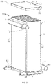
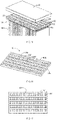
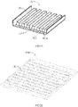
- FIG. 1 is a schematic structural view of a heat exchanger 100 according to an exemplary embodiment of the present application.
- the heat exchanger 100 can be used as a condenser, an evaporator and other heat exchange device.
- the heat exchanger 100 can be applied to various heat exchange systems, such as a CO2 refrigeration system, and is also applicable to automotive industries.
- the heat exchanger 100 includes a first header box 1, a second header box 2, a core 3 and a casing 4.
- the first header box 1 and the second header box 2 are located at two ends of the casing 4.
- the structure of the casing 4 will be described in detail in the following embodiments, and will not be described here.
- a chamber 400 is formed inside the casing 4, and part or all of the core 3 is accommodated in the chamber 400.
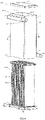
- the core 3 includes a plurality of flat tubes 30 for circulating a first heat exchange medium.
- the flat tubes 30 are arranged at intervals in the chamber 400 inside the casing 4 so as to divide the chamber 400 into a plurality of heat exchange channels 401 for circulating a second heat exchange medium. Wherein adjacent heat exchange channels 401 may be connected or disconnected, which is not limited in this application, and can be set according to specific application environment.
- the number of the flat tubes 30 may be one or more.
- the flat tube may be a microchannel flat tube, which includes a plurality of micro channels 302 arranged in a width direction of the flat tube 30 (refer to FIG. 17 ). By using of the microchannel flat tube, it can better increase the strength of the flat tubes, thereby improving the stability and safety of the heat exchanger. If there are multiple flat tubes, the multiple flat tubes may be arranged in parallel at intervals. In addition, each layer of the flat tubes may be a flat tube or a wide flat tube formed by arranging multiple flat tubes in the same plane. This application does not specifically limit the type, number and installation method of the flat tubes, which can be determined according to application environment.
- the first header box 1 includes a first bottom plate 10 and a cover plate 11.
- the first bottom plate 10 includes a first surface 101 and a second surface 102 opposite to the first surface 101. At least a portion of the first surface 101 is recessed inwardly to form at least one first hole 105 which extends along a length direction L1 of the first bottom plate 10. At least a portion of the second surface 102 is recessed inwardly to form at least two second holes 106 which extend along a width direction W1 of the first bottom plate 10.
- the first hole 105 is communicated with the at least two second holes 106, so that the fluid (the first heat exchange medium) flowing through the first hole 105 can be distributed to the at least two second holes 106, or the first heat exchange medium flowing through the second hole 106 can be collected into the first hole 105 to make the distribution of the first heat exchange medium more uniform.
- the first bottom plate 10 has a simple structure, a small volume and a lighter weight, which is beneficial to reduce the amount of materials and thus to reduce the weight of the heat exchanger.
- the cover plate 11 is attached to the first surface 101 and closes an opening 1051 of the first hole 105.
- the first bottom plate 10 may be an integrally formed plate, or may be formed by splicing two or more plates, for example, by welding multiple plates.
- the multiple plates have the first hole 105 and the second hole 106.
- the first bottom plate 10 is a plate structure (refer to FIGS. 9 to 15 ).
- the side of the first bottom plate 10 close to the cover plate 11 is a first surface 101, and the side of the first bottom plate 10 away from the cover plate 11 is a second surface 102.
- the first bottom plate 10 includes a first plate-shaped member 1001 and a second plate-shaped member 1002 welded together (refer to FIG. 16 ).
- the first plate-shaped member 1001 is attached to a side of the second plate-shaped member 1002 close to the cover plate 11.
- the side of the first plate-shaped member 1001 adjacent to the cover plate 11 is a first surface 101
- the side of the second plate-shaped member 1002 away from the cover plate 11 is a second surface 102.
- the first plate-shaped member 1001 has a first hole 105
- the second plate-shaped member 1002 has a second hole 106.
- the first hole 105 extends through the first plate-shaped member 1001, and the second hole 106 extends through the second plate-shaped member 1002.
- the second hole 106 includes a first opening communicated with the first hole 105 and a second opening away from the first hole 105.
- the cross-sectional area of the first opening is larger than a cross-sectional area of the second opening.
- the first header box 1 includes a second bottom plate 12 in addition to the first bottom plate 10 and the cover plate 11.
- the second bottom plate 12 is disposed on a side of the first bottom plate 10 facing away from the cover plate 11.
- the second bottom plate 12 is provided with a third hole 108 corresponding to the second hole 106.
- a cross-sectional area of the third hole 108 is smaller than the cross-sectional area of the second hole 106.
- An end surface of one end of the flat tube 30 can be located in the second hole 106 to form a gap between an outer wall surface of the flat tube 30 and an inner wall surface of the second hole 106, which can effectively prevent solder between the first bottom plate 10 and the second bottom plate 12 from clogging an opening of the flat tube 30, and also help prevent solder between the cover plate 11 and the first bottom plate 10 from clogging the opening of the flat tube 30.
- An edge of the third hole 108 extends a predetermined distance away from a side of the cover plate 11 to form a flange 107. It saves a layer of plate members and ensures insertion depth of the flat tube 30, thereby ensuring a welding area between the end of the flat tube 30 and the first header box 1, which is beneficial to improve the welding strength of the structure.
- the end of the flat tube 30 may be provided with a constricted portion 301 which includes a side wall 3012 and a positioning surface 3011 (refer to FIG. 17 ).
- Part of the constricted portion 301 is inserted into the third hole 108, and the other part is inserted into the second hole 106 and fits an inner surface of the side wall 3012 and the flange 107, an inner surface of the third hole 108 and an inner surface of the second hole 106.
- the positioning surface 3011 abuts against the end surface of the flange 107 to facilitate the installation and positioning of the flat tube 30, and reduce the difficulty of assembling the flat tube 30 and the first header box 1.
- the constricted portion 301 can be obtained by necking processing through a necking tool.
- a height h of the constricted portion 301 can be set according to a depth required for the flat tube 30 to be inserted into the second hole 106.
- the second header box 2 can be used as a lower header box.
- the second header box 2 includes a cover plate 21 and a third bottom plate 20 (refer to FIG. 9 ).
- the cover plate 21 is provided with a groove 211 extending along a longitudinal direction L2 of the cover plate 21.
- the groove 211 includes an opening portion 211a which is provided toward the third bottom plate 20.
- the third bottom plate 20 is provided with a fourth opening 201 communicating with the opening portion 211a.
- one end of the flat tube 30 can be inserted into a fourth opening 201.
- an extending direction of the fourth opening 201 is perpendicular to the extending direction of the groove 211.
- the third bottom plate 20 may be an integrally formed plate, or may be formed by splicing two or more plates, for example, by welding multiple plates.
- the plurality of plates have openings forming the fourth opening 201.
- the third bottom plate 20 includes a third plate-shaped member 2001 connected to the cover plate 21 and a fourth plate-shaped member 2002 away from the cover plate 21.
- the third plate-shaped member 2001 defines a first hole portion 2011 forming a fourth opening 201
- the fourth plate-shaped member 2002 defines a second hole portion 2012 forming the fourth opening 201.
- the first hole portion 2011 extends through the third plate-shaped member 2001
- the second hole portion 2012 extends through the fourth plate-shaped member 2002.
- a cross-sectional area of the first hole portion 2011 is larger than a cross-sectional area of the second hole portion 2012.
- the other end surface of the flat tube 30 may be located in the first hole portion 2011, and a gap is formed between the outer wall surface of the flat tube 30 and the inner wall surface of the first hole portion 2011. It can effectively prevent the solder between the third plate-shaped member 2001 and the fourth plate-shaped member 2002 from clogging the opening of the flat tube 30, and also help prevent the solder between the cover plate 21 and the third plate-shaped member 2001 from clogging the opening of the flat tube 30.
- An edge of the fourth opening 201 extends toward a side away from the cover plate 21 by a predetermined distance to form a flange 207. While saving a layer of plates, an insertion depth of the flat tube 30 can be ensured, thereby ensuring a welding area between the end of the flat tube 30 and the second header box 2, which is beneficial to improve the strength of the structure.
- the end of the flat tube 30 inserted into the fourth opening 201 may also be provided with a constricted portion. For details, reference may be made to the related description of the above-mentioned constricted portion 301, which will not be repeated here.
- a partition 212 is provided in the groove 211 to divide the groove 211 into first and second chambers 213, 214 separated from each other.
- the first chamber 213 and the second chamber 214 are substantially distributed along the length of the groove, so that the plurality of flat tubes 30 can be divided into a first tube group 31 which is communicated with the first chamber 213 and an interior of the first header box 1 (such as the first hole 105), and a second tube group 32 which is communicated with the second chamber 214 and an interior of the first header box 1 (such as the first hole 105) in order to increase the flow of the first heat exchange medium.
- This is also beneficial to increase the flow rate of the first heat exchange medium and improve the heat exchange efficiency of the heat exchanger.
- the groove can also be divided into more than three chambers. This application does not limit this, and can be set according to the specific application environment.
- one end of the cover plate 21 is provided with a first header 5 communicated with the first chamber 213, and the other end is provided with a second header 6 communicated with the second chamber 214.
- One end of the first header 5 is sealed, and the other end is provided with a first external pipe 52 for the first heat exchange medium to flow into the first header 5 or flow out of the first header 5.
- One or more header holes 51 are opened on the side of the first collecting tube 5 close to the second header box 2.
- the header holes 51 are communicated with the first chamber 213 for the first heat exchange medium to flow into or out of the second header box 2.
- One end of the second header 6 is sealed, and the other end is provided with a second external pipe 62 for the first heat exchange medium to correspondingly flow out of the second header 6 or flow into the second header 6.
- the side of the second header 6 close to the second header box 2 is also provided with one or more header holes (not shown).
- the header holes are communicated with the second chamber 214 for the first heat exchange medium to correspondingly flow out of the second header box 2 or flow into the second header box 2.
- the first heat exchange medium may enter the first header 5 from the first external pipe 52, flow from the first header 5 into the first chamber 213 of the second header box 2, flow into the first header box 1 through the first tube group 31, then flow into the second tube group 32 from the first hole 105 of the first header box 1, and then enter the second chamber 214, and finally flow out through the second external pipe 62 of the second header 6.
- the first heat exchange medium completes a heat exchange process.
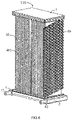
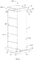
- the casing 4 includes a lateral wall 40.
- a first end 403 of the casing 4 is closed and a second end 405 of the casing 4 is open to facilitate the installation of the first header box 1, the core 3 and other components.
- the lateral wall 40 may include four plates including a first side wall 41, a second side wall 42, a third side wall 43 and a fourth side wall 44.
- the first side wall 41, the second side wall 42, the third side wall 43 and the fourth side wall 44 may be integrally formed, or may be welded together.
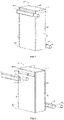
- the cover plate 11 includes a main body portion 112 at a top end and connecting portions 113 extending downwardly from outer edges of the main body portion 112.
- At least part of the inner side of the lateral wall 40 is welded to a peripheral side wall 103 of the first bottom plate 10 (or a peripheral side wall 103 of the first bottom plate 10 and a peripheral side wall of the second bottom plate 12) in order to increase the welding area of the cover plate 11 and the lateral wall 40, thereby improving the welding strength of the casing 4.
- an inside of the connecting portion 113 may be only welded to the peripheral side wall 103 of the first bottom plate 10, or welded to the peripheral side wall 103 of the first bottom plate 10 and the peripheral side wall of the second bottom plate 12.
- the end of the lateral wall 40 is welded to the second bottom plate 12.
- the casing 4 further includes a top wall 46 at the first end 403.
- the top wall 46 can be integrally formed with the lateral wall 40 (refer to FIGS. 5 , 7 and 8 ).
- the first header box 1 may not be provided with a cover plate.
- the top wall may serve as a cover plate to block the opening of the first hole 105.
- the top wall 46 can also be set independently from the lateral wall 40, which is not limited in this application and can be set according to the specific application environment.
- the first header box 1 may also be provided with a separate cover plate.
- cover plate 11 may not include the connecting portion 113, and the two ends of the side wall may be welded to the second and third bottom plates, respectively.
- the two ends of the side wall can be welded to the first bottom plate and the third bottom plate, respectively.
- the two ends of the side wall of the casing 4 are provided with opening sections 411, 433 communicating with the chamber 400.
- the opening sections 411, 433 extend in a stacking direction of the flat tubes 30.
- the third header 7 and the fourth header 8 extend along the stacking direction of the flat tubes 30.
- the third header 7 and the fourth header 8 communicate with the chamber 400 through the opening sections 411, 433, respectively, so as to collect or distribute the second heat exchange medium. Relevant descriptions of the third header 7 and the fourth header 8 are as follows.
- an assembly including the third and fourth headers 7, 8 and the casing 4 and so on serves as an outer core assembly 120
- an assembly including the first first header box 1, the flat tubes 30 and the second second header box 2 and so on serves as an inner core assembly 110.
- the outer core assembly 120 and the inner core assembly 110 can be assembled together by nesting to facilitate the installation of the whole heat exchanger.
- the first header box 1 includes a cover plate 11 and a first bottom plate 10.
- the cover plate 11 is provided with a groove 111 extending along the length direction of the cover plate.
- the groove 111 is open on one side adjacent to the first bottom plate 10. Accordingly, the groove 111 includes an opening portion 111a adjacent to the first bottom plate 10.
- the first bottom plate 10 is provided with an opening 1010 (refer to FIGS. 19 and 20 ) into which the flat tube 30 is inserted.
- the opening 1010 may be generally strip-shaped to form a longitudinal slot.
- the opening 1010 extends through the upper and lower surfaces of the first bottom plate 10.
- an extending direction of the groove 111 and the extending direction of the opening 1010 may be substantially perpendicular. It should be noted that minor deviations due to processing should be understood to be within the scope of this protection.
- a cross section of the groove 111 may be semicircular, triangular, rectangular, semi-elliptical, or a combination of two or more of the above shapes.
- the opening 1010 includes a first opening adjacent to the cover plate 11 and a second opening away from the cover plate 11.
- a cross-sectional area of the first opening is larger than a cross-sectional area of the second opening.
- At least a part of the opening portion 111a communicates with the first opening, so that the first heat exchange medium flows through the groove 111 and the opening 1010 to the flat tube 30 in sequence.
- This application does not limit the number of the grooves 111 and the number of the openings 1010, which can be determined according to specific application environment.
- the opening 1010 may be a stepped hole, which is beneficial to increase the flow rate of the first heat exchange medium when entering the opening 1010 from the first opening.
- the opening 1010 may not be a stepped hole.
- the opening 1010 has a substantially trumpet shape.
- the cover plate 11 has two opposite side walls 114, and the first bottom plate 10 has two corresponding end surfaces.
- the two end surfaces facing the side walls of the cover plate 11 extend to form a hem 121 to cover the two side walls 114 of the cover plate 11, which is beneficial to increase the welding area of the cover plate and the bottom plate, thereby enhancing the structural strength of the header box.
- the length direction L2 of the hem 121 and the length direction L1 of the cover plate 11 may be substantially the same.
- the bottom plate is an integrally formed plate.
- the bottom plate adjacent to an inner surface of the hem 121 may be provided with a positioning groove 123.
- a length direction L3 of the positioning groove 123 is substantially the same as the length direction L2 of the hem 121.
- the positioning groove 123 has a bottom wall and two side walls.
- the hem 121 includes an inner wall 1211 facing the side wall 114. Wherein one side wall of the positioning groove 123 and the inner wall 1211 may be located substantially in the same plane.
- the first bottom plate 10 includes a first plate-shaped member 1200 provided with the hem 121 and a second plate-shaped member 1300 welded between the first plate-shaped member 1200 and the cover plate 11.
- the opening 1010 includes a first hole portion 1011 and a second hole portion 1012.
- the first hole portion 1011 extends through the first plate-shaped member 1200
- the second hole portion 1012 extends through the second plate-shaped member 1300 (refer to FIGS. 19, 20 , 22 and 23 ).
- a gap is formed between the hem 121 and an end surface of the second plate-shaped member 1300 adjacent to the hem 121 so as to form the positioning groove 123 for receiving the side wall 114 of the cover plate 11.
- the second plate-shaped member 1300 includes an end surface 1311 adjacent to the hem 121.
- the end surface 1311 may serve as a side wall of the positioning groove 123, and a portion of the inner wall 1211 may serve as another side wall of the positioning groove 123.
- the first plate-shaped member 1200 includes the hem 121 and a main body member 1250 provided with a first hole portion 1011.
- the hem 121 and the main body member 1250 may be formed integrally.
- the hem 121 may be bent from a plate-shaped member, or may be connected by welding.
- the main body member 1250 includes a surface 1251 adjacent to a side of the second plate 1300, and at least a part of the surface 1251 can serve as a bottom wall of the positioning groove 123.
- An edge of the opening 1010 extends a predetermined distance away from the side of the cover plate 11 to form a flange 124.
- the depth of the opening 1010 is ensured so as to ensure the insertion depth of the flat tube 30.
- welding between plates is reduced, which is beneficial to manufacture.
- the cover plate 11 includes a plurality of grooves. Reinforcement ribs 1132 are formed between two adjacent grooves. An end surface S1 of the reinforcement rib 1132 is substantially flat. Wherein the end surfaces S1 of the plurality of reinforcement ribs 1132 are approximately in the same plane (refer to FIGS. 21 and 25 ), so that the portion of the cover plate 11 that contacts the first bottom plate 10 can be fitted and sealed.
- the two side walls 114 of the cover plate 11 extend a certain distance from the plane defined by S1 to form protrusions 1141. At least part of the structure of the protrusions 1141 can be inserted into the positioning grooves 123. Therefore, the welding area between the cover plate and the bottom plate is further increased, and the structural strength of the header box is enhanced.
- one end of the cover plate 11 is provided with a notch 115 communicating with the groove 111.
- a blocking member 116 is provided in the notch 115 to seal the end of the groove 111.
- the other end of the cover plate 11 is connected with a first header 5 which is communicated with the groove 111 to collect or distribute the first heat exchange medium.
- An opening 51 communicating with the groove 111 is opened on a side of the first header 5 adjacent to the cover plate 11.
- one end of the first header 5 is sealed, and the other end is provided with an external pipe 52.
- the notch may not be provided, and the blocking member 116 and the cover plate 11 are integrally formed, or when processing the cover plate, one end of the groove does not penetrate.
- two ends of the cover plate 11 are respectively provided with two headers communicating with the groove 111.
- a partition is provided in the groove 111 to divide the groove 111 into at least two mutually isolated chambers.
- the at least two mutually isolated chambers are arranged along the length direction L1 of the cover plate 11 to increase the flow of the first heat exchange medium and improve the heat exchange efficiency.
- the two headers are respectively connected to one chamber.
- the end portion of the flat tube 30 may be provided with the constricted portion 301.
- the constricted portion 301 includes a side wall 3012 and a positioning surface 3011.
- the constricted portion 301 is inserted into the opening 1010, the side wall 3012 is in contact with the inner wall of the opening 1010, and the positioning surface 3011 abuts against the end surface 1241 of the flange 124, in order to facilitate the installation and positioning of the flat tube 30, and reduce the difficulty of assembling the flat tube and the header box.
- the constricted portion 301 can be obtained by necking processing by a necking tool.
- the height h of the constricted portion 301 can be set according to the depth of the flat tube 3 required to be inserted into the opening 1010.
- the end surface of the flat tube 30 may extend through the first hole portion 1011 and be placed in the second hole portion 1012.
- a gap can be formed between the outer wall surface of the flat tube 30 and the inner wall surface of the first hole portion 1011. The solder between the first plate-shaped member 1200 and the second plate-shaped member 1300 can be effectively prevented from clogging the opening of the flat tube 30.
- the second header box 2 has a bottom plate and a cover plate, and the bottom plate of the second header box 2 is provided with a corresponding opening for the other end of the flat tube 3 to be inserted, so that the flat tube 3 and the second header box 2 are internally communicated.
- the second header box 2 is provided with a second header 6 communicating with the second header box 2 to collect or distribute the first heat exchange medium.
- one end of the second header 6 is sealed, and an external pipe 62 is provided at the other end of the second header 6.
- the structure of the second header box 2 is basically the same as that of the first header box 1. For details, reference may be made to the relevant description of the first header box 1, which will not be repeated here.
- the first and second headers 5, 6 may be located on the same side outside of the casing 4.
- the first and second headers 5, 6 can also be located on different sides outside of the casing 4.
- the first and second headers 5, 6 are located approximately and diagonally outside of the casing 4, which makes the distribution of the first heat exchange medium more uniform and improves the heat exchange effect.
- the first heat exchange medium and the second heat medium form countercurrent heat exchange, which makes the heat exchange between the two more sufficient. It can be set according to application environment, which is not limited in this application.
- only one of the first and second ends of the casing may be provided with a header box.
- a header box for the setting of the header box, please refer to the related description above, which will not be repeated here.
- the side wall of the casing 4 is provided with a third header 7 and a fourth header 8.
- the third header 7 and the fourth header 8 extend along the stacking direction of the flat tubes 30.
- the third header 7 and the fourth header 8 are communicated with the chamber 400 through the opening sections 411, 433, respectively, to collect or distribute the second heat exchange medium.
- the first header box 1 includes a cover plate 11 and a first bottom plate 10.
- the cover plate 11 is provided with a groove 111 extending along a length direction L of the cover plate 11.
- the groove 111 includes an open end 111a adjacent to the first bottom plate 10.
- the first bottom plate 10 is provided with an elongated opening 1010 (refer to FIG. 33 ) into which the flat tube 30 is inserted.
- the elongated opening 1010 includes a first opening 1010a close to the cover plate 11 and a second opening 1010b away from the cover plate 11.
- a cross-sectional area of the first opening 1010a is greater than a cross-sectional area of the second opening 1010b.
- At least part of the open end 111a is communicated with the first opening 1010a (refer to FIG. 33 ) so that the first heat exchange medium flows through the groove 111 and the elongated opening 1010 to the flat tube 30 in sequence.
- This application does not limit the number of the grooves 111 and the number of elongated openings 1010, which can be determined according to specific application environment.
- the first heat exchange medium flows into the flat tube through the elongated hole of which an opening area becomes from large to small, thereby reducing the resistance of the first heat exchange medium flowing in the header box.
- a cross section of the groove 111 may be semicircular, triangular, rectangular, semi-elliptical, or a combination of two or more of the above shapes.
- the first bottom plate 10 may be a flat plate with the elongated holes.
- the cover plate 11 includes a plurality of groove edges 117 on both sides of the groove.
- the end surfaces S1 of the groove edges 117 are substantially flat. Wherein the end surfaces S1 of the plurality of groove edges 117 are substantially in the same plane (refer to FIG. 34 ), so that the portion of the cover plate 11 that contacts the first bottom plate 10 can be fitted and sealed.
- the elongated opening 1010 may be a stepped hole (refer to FIG. 31 ), which is beneficial to increase the flow rate of the first heat exchange medium entering the elongated opening 1010 from the first opening. That is, it is beneficial to increase the flow rate of the first heat exchange medium.
- the length direction of the elongated opening 1010 may be substantially the same as the width direction W of the cover plate 11. Of course, it may not be the same.
- the bottom plate may be an integrally formed plate, or may be formed by splicing two or more plates, for example, by welding multiple plates.
- the plurality of plate member are provided6 with holes which form the elongated openings 1010.
- the first bottom plate 10 includes a first plate-shaped member 1001 connected to the cover plate 11, a third plate-shaped member 1003 away from the cover plate, and a second plate-shaped member 1002 disposed between the first plate-shaped member 1001 and the third plate-shaped member 1003 (refer to FIGS. 29 , 31 and 32 ).
- the first plate-shaped member 1001, the second plate-shaped member 1002, and the third plate-shaped member 1003 can be joined by welding.
- the elongated opening 1010 includes a first hole portion 1011, a second hole portion 1012 and a third hole portion 1013 (refer to FIG. 31 ).
- the first hole portion 1011 extends through the first plate-shaped member 1001, the second hole portion 1012 extends through the second plate-shaped member 1002, and the third hole portion 1013 extends through the third plate-shaped member 1003.
- directions of the side walls of the third hole portion 1013, the second hole portion 1012 and the first hole portion 1011 extend in consistent with a length direction of the flat tube 30 (refer to FIG. 31 ).
- a width D3 of the third hole portion 1013 is equal to a thickness T of the flat tube, so as to ensure that the flat tube fits with the third hole portion 1013, and prevent the first heat exchange medium from leaking out of the header box.
- a width D2 of the second hole portion 1012 is greater than the width D3 of the third hole portion 1013.
- D2 1.5*D3.
- a width D1 of the first hole portion 1011 is greater than or equal to the width D2 of the second hole portion 1012.
- D1 1.5*D2.
- a size range of the width D1 of the first hole portion 1011 may be approximately in a range of 3.375mm to 5.625mm.
- the opening 1010 may not be a stepped hole.
- the opening 1010 is substantially trumpet-shaped (refer to FIG. 31B ).
- the first bottom plate 10 is formed by welding the first plate-shaped member 1001 and the second plate-shaped member 1002.
- the opening 1010 includes a first hole portion 1011 and a second hole portion 1012. Among them, the first hole portion 1011 extends through the first plate-shaped member 1001 and the second hole portion 1012 extends through the second plate-shaped member 1002.
- the first hole portion 1011 has a substantially trumpet shape, and an end with a larger opening of the first hole portion 1011 is closer to the cover plate 11 than another end with a smaller opening.
- the width D3 of the third hole portion 1013 is smaller than the thickness T of the flat tube in order to ensure that the flat tube and the third hole portion 1013 are fitted together.
- the end of the flat tube 30 extends through the third hole portion 1013 and is closer to the cover plate 11 than the third hole portion 1013.
- the end of the flat tube 30 is located in the second hole portion 1012, so that a gap is formed between the outer wall surface of the flat tube 30 and the inner wall surface of the second hole portion.
- the solder between the third plate-shaped member 1003 and the second plate-shaped member 1002 can be effectively prevented from clogging the opening of the flat tube 30.
- the second header box 2 has a bottom plate 20 and a cover plate 21, and the bottom plate of the second header box 2 is provided with a corresponding elongated hole for the other end of the flat tube 30 to be inserted, so that the flat tube 30 is communicated with the interior of the second header box 2.
- the structure of the second header box 2 is basically the same as that of the first header box 1. For details, please refer to the relevant description of the first header box 1.
- two ends of the casing 4 are provided with headers for the first heat exchange medium to flow into and flow out of the header box.
- a first end 403 of the casing 4 is provided with a first header 5, and a second end 405 is provided with a second header 6.
- the first header 5 is communicated with the first header box 1, and the second header 6 is communicated with the second header box 2.
- one end of the groove 111 is blocked, and the other end has an opening 1112.
- the opening 1112 is connected to the first header 5 which collects or distributes the first heat exchange medium.
- a side of the first header 5 facing the first header box 1 is provided with a header hole 51 corresponding to the opening 1112 for the first heat exchange medium to enter and exit the first header box 1 (refer to FIGS. 34 and 35 ).
- the structure of the groove 211 on the cover plate 21 of the second header box 2 is basically the same as that of the groove 111.
- the second header 6 is provided with a corresponding header hole 61 for the first heat exchange medium to enter and exit the second header box 2 (refer to FIGS. 29 and 36 ).
- first header 5 One end of the first header 5 is sealed, and the other end is provided with a first external pipe 52 for the first heat exchange medium to flow into the first header 5 or flow out of the first header 5.
- first external pipe 52 One end of the second header 6 is sealed, and the other end is provided with a second external pipe 62 corresponding to the first heat exchange medium to flow out of the second header 6 or flow into the second header 6.
- first header 5 and the second header 6 are arranged diagonally outside of the casing 4, which makes the distribution of the first heat exchange medium more uniform and improves the heat exchange effect.
- first heat exchange medium and the second heat medium form countercurrent heat exchange, which makes the heat exchange between the two more sufficient. It can be set according to application environment, which is not limited in this application.
- the cover plate 11 of the first header box 1 is provided with a partition plate 1130.
- a lower end surface of the partition plate 1130 abuts against an upper surface of the first bottom plate 10 so as to divide the groove 111 into at least two mutually isolated chambers 15 and 16.
- the cover plate 11 may be provided with a row of first partition holes 118 in which a partition plate 1130 is inserted to divide the groove 111 into two mutually isolated chambers 15 and 16 (that is, an internal space of the first header box 1 is divided into two mutually isolated chambers 15 and 16) (refer to FIGS. 28 , 29 , 35 , 37 and 38 ).
- the first partition hole 118 is provided along the width direction W of the cover plate 11 so that the chamber 15 and the chamber 16 are distributed along the length direction L of the cover plate 11.
- the cover plate 21 may also be provided with a partition plate 2130, an upper end surface of the partition plate 2130 abuts against a lower surface of the bottom plate 20 so as to divide the groove 211 of the second header box 2 into two mutually isolated chambers 25 and 26.
- the cover plate 21 may also be provided with a row of second partition holes (not shown) for inserting the partition plate 2130. For details, reference may be made to the relevant description of the cover plate 11, which will not be repeated here.
- first partition hole 118 and the second partition hole are juxtaposed along the stacking direction of the flat tubes 30 (that is, they are staggered along a direction indicated by the directional arrow 101 shown in FIG. 37 ).
- the partition plate 1130 and the partition plate 2130 are staggered along the stacking direction of the flat tubes 30 (refer to FIGS. 37 and 38 ), so that the plurality of flat tubes 30 can be divided into a first tube group 31 communicating with the chamber 15 and the chamber 25, a second tube group 32 communicating with the chamber 25 and the chamber 16, and a third tube group 33 communicating with the chamber 16 and the chamber 26.
- the flow of the first heat exchange medium is increased, which is beneficial to increase the flow rate of the first heat exchange medium, thereby improving the heat exchange efficiency of the heat exchanger.
- the number of flat tubes included in the first tube group 31, the second tube group 32 and the third tube group 33 is different.
- the number N1 of flat tubes in the first tube group 31, the number N2 of flat tubes in the second tube group 32, and the number N3 of flat tubes in the third tube group 33 may meet the following relationship: N1> N2> N3.
- N1:N2:N3 10:7:4.
- the first heat exchange medium When the heat exchanger is working under an evaporator working mode, the first heat exchange medium enters from the first header 5 and flows out of the second header 6 after heat exchange.
- the specific flow direction of the first heat exchange medium can be referred to the directional lines in FIG. 38 .
- the first heat exchange medium When the heat exchanger is working under a condenser working mode, the first heat exchange medium enters from the second header 6 and flows out of the first header 5 after heat exchange.
- the specific flow direction of the first heat exchange medium can be referred to the directional lines in FIG. 37 . As a result, the flow of the first heat exchange medium in the heat exchanger is increased, and the flow speed of the first heat exchange medium is increased as well.
- cover plate 11 may be provided with a row of first partition holes.
- multiple rows of the first partition holes may be provided to divide the groove of the first header box 1 into more mutually isolated chambers in order to further increase the flow of the first heat exchange medium.
- the cover plate 21 of the second header box 2 can also be provided with a row of second partition holes or multiple rows of second partition holes.
- only one of the cover plate 11 and the cover plate 21 may be provided with a row of partition holes, while the other is not provided with partition holes. This application does not limit this.
- the number of rows of the partition holes provided in the cover plate 11 and the cover plate 21 may be the same or different. This application does not limit this, which can be determined according to specific application environment.
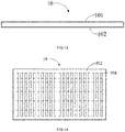
- the heat exchange channel 401 is provided with a heat dissipation member 39 which may be heat exchange fins, such as saw-tooth heat exchange fins, corrugated heat exchange fins, or the like.
- a heat dissipation member 39 which can be fixedly disposed on the bottom plate of the header box through the end portion, or fixedly disposed on the bottom of the header box through the limiting member, or fixedly mounted on the flat tube by brazing, or the like.
- a flow channel 390 is provided for circulation of the second heat exchange medium.
- the flow channel 390 is communicated with the opening sections 411, 433.
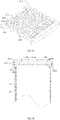
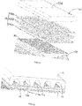
- the heat dissipation member 39 is composed of two or more racks 97 which are arranged in parallel (refer to FIGS. 40A , 40C and 40D ).
- the rack 97 includes two or more convex frames 971 arranged at intervals.
- the convex frame 971 includes a convex frame top 9711 and folding plates 9712 connected to both ends of the convex frame top 9711, respectively.
- the angle ⁇ between the folding plate 9712 and the convex frame top 9711 is greater than 90°, so that a cross-section of the convex frame 971 may be substantially trapezoidal.
- the convex frames of adjacent racks are staggered along a rack length direction (a direction indicated by arrow C in FIG. 40D and its opposite direction).
- the second heat exchange medium flows along a direction shown by arrow B in FIG. 40D or its opposite direction, which destroys the boundary layer between the second heat exchange medium and the heat dissipation member 39, increasing the perturbation of the heat exchange medium, thereby increasing the heat transfer coefficient of the second heat exchange medium on the surface of the heat dissipation member 39.
- the resistance of the heat exchange fins to the flow of the second heat exchange medium is reduced to a greater extent.
- the heat dissipation member 39 has a notch 391 on a side adjacent to the opening section 411, and a notch 392 on a side adjacent to the opening section 433 (refer to FIGS. 28 to 30 and FIGS. 39A to 40D ).
- the notches 391 and 392 form a flow channel 390 for circulation of the second heat exchange medium, so that the chamber 40 can communicate with the opening sections 411, 433 to reduce the flow resistance to the second heat exchange medium.
- the height of the side of the flow channel 390 adjacent to the opening section 411 is greater than the height of the side away from the opening section 411.
- the height d of the end of the flow channel 390 adjacent to the opening section 411 and the width D of the heat dissipation member 39 meet the condition:0.15D ⁇ d ⁇ 0.25D, in order to ensure the inflow of the second heat exchange medium and the effective heat exchange area of the heat dissipation member 39.
- the value of d is 0.2D.
- the heat dissipation member 39 includes a body portion. Part of the body portion extends toward two ends to form a limiting portion 393 to facilitate positioning of the heat dissipation member 39 and to ensure the size of the heat dissipation member 39.
- the limiting portion 393 is located on a side away from the opening section 411. Wherein the corresponding end of the heat dissipation member 39 at the notch portion 391 has an inclined edge 394 (see FIG. 40A ), and the corresponding end of the heat dissipation member 39 at the notch 392 also has an inclined edge.
- the end surface of the limiting portion 393 is a straight edge. Wherein the length L of the end surface may be approximately in a range of 5mm to 10mm, to ensure the fixing of the heat dissipation member 39 and the flow of the second heat exchange medium.
- the inclined edge 394 may be a straight edge (see FIG. 40A ).
- the inclined edge 394 may also be a stepped edge (see FIG. 40B ), an arc-shaped edge, or the like. This application does not limit this, which can be set according to specific application environment.
- Shape of the notch 392 may be substantially the same as the notch 391.
- the end of the heat dissipation member 39 may be substantially straight.
- the upper end of the heat dissipation member 39 is located substantially below the opening section 411 of the side wall to form the flow channel 390, thereby ensuring the smooth flow of the second heat exchange medium into the chamber 40. That is to ensure that the second heat exchange medium flows smoothly into the heat exchange channel 401 (refer to FIGS. 39B , 39D and 39E ).
- a limiting member 395 is provided on one side of the header box 1, 2 adjacent to the core 3. One end of the limiting member 395 abuts against the end of the heat dissipation member 39, and the other end is disposed on the header box 1, 2. At the same time, the limiting member 395 is partially or entirely located on the side of the flow channel 390 away from the opening section 411, 433. The end of the heat dissipation member 39 is substantially straight, then a flow channel 390 for circulation of the second heat exchange medium is formed between the header box and the end of the heat dissipation member, so that the chamber 40 can be communicated with the opening section 411, 433 in order to reduce the flow resistance to the second heat exchange medium.
- the second bottom plate 12 is provided with a slot 109 for inserting the limiting member 395.
- the slot 109 is located at an end of the second bottom plate 12 away from the opening section 411, and the slot 109 is located between adjacent elongated openings 1010.
- An extending direction of the slot 109 may be the same as the extending direction of the elongated opening 1010, or may be different.
- the extending length of the slot 109 is smaller than the extending length of the elongated opening 1010.
- the limiting member 395 may be an independent component, and may be disposed on the second bottom plate 12 by welding. Of course, the limiting member 395 can also be provided integrally with the second bottom plate 12.
- the limiting member 395 may have various shapes.
- a cross-sectional surface of the limiting member 395 may be one of a triangular shape, a rectangular shape, a semicircular shape and an oval shape, or a combination of multiple shapes.
- the two flow channels 390 at opposite ends of the heat dissipation member 39 may be substantially the same (refer to FIG. 39A ) or different (refer to FIG. 39D ), and can be set according to specific application environment, which is not limited by the present application.
- heat dissipation member 39 can also be directly fixed to the flat tube, and does not need to be arranged through the limiting member.
- the relationship between the width W of the heat exchange channel 401 and the thickness T of the flat tube 30 meets the condition: 2T ⁇ W ⁇ 3.25T.
- the width W of the heat exchange channel 401 is approximately in a range of 3mm to 8.125mm.
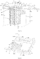
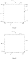
- the third header 7, the fourth header 8 and the casing 4 are independent components (refer to FIG. 41A ).
- the side of the third header 7 adjacent to the casing 4 is provided with a hole 71 corresponding to the opening section 411, and the side of the fourth header 8 adjacent to the casing 4 is provided with a hole 81 corresponding to the opening section 433 for the second heat exchange medium to enter and exit the heat exchange channel 401.
- the third and fourth headers 7, 8 and the casing 4 can also be integrally formed (see FIG. 41B ).
- One end of the third header 7 is sealed, and the other end is provided with a third external pipe 72 in order for the second heat exchange medium to flow into or out of the third header 7.
- One end of the fourth header 8 is sealed, and the other end is provided with a fourth external pipe 82 in order for the corresponding second heat exchange medium to the flow out of the fourth header 8 or to flow into the fourth header 8 (refer to FIG. 29 ) ).
- the second heat exchange medium may flow into the fourth header 8 from the fourth external pipe 82, and then enter the heat exchange channel to exchange heat with the first heat exchange medium through the flat tube, then flow into the third header 7, and finally flow out from the third external pipe 72, as shown by the directed lines in FIG. 41A or FIG. 41B .
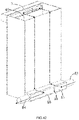
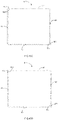
- two ends of the third header 7 are sealed, and fifth and sixth external pipes 83 and 84 are provided at both ends of the fourth header 8, respectively (refer to FIG. 42 ).
- the fourth header 8 is provided with a partition plate 88 to divide an internal space of the fourth header 8 into two header chambers 85 and 86 isolated from each other.
- the header chamber 85 is communicated with the fifth external pipe 83
- the header chamber 86 is communicated with the sixth external pipe 84, so that the second heat exchange medium can enter the corresponding heat exchange channel from the fifth external pipe 83.
- the sixth external pipe 84 After changing the flow direction through the third header 7, it flows out of the sixth external pipe 84 after flowing through another part of the heat exchange channels, as shown by the directional lines in FIG. 42 . It can be seen that with this arrangement, the heat exchange process of the second heat exchange medium can be increased, which is beneficial to increase the flow rate of the second heat exchange medium, thereby improving the heat exchange efficiency of the heat exchanger.
- the third header 7 and the fourth header 8 are arranged diagonally outside of the casing 4 so that the second heat exchange medium and the first heat exchange medium can form countercurrent heat exchange, so that the heat exchange between the two is more sufficient.
- the third header and the fourth header can also be set in other ways, and can be set according to specific application environment, which is not limited in this application.
- the above-mentioned casing 4 may include only side walls, and the bottom plates 10 and 20 of the header boxes 1 and 2 provided at two ends jointly form a sealed chamber together with the casing 4.
- the casing may also include an end wall (not shown) that can be closely attached to the bottom plate of the header box to form the chamber, and the end wall should be provided with a hole through which the flat tube extends.
- the casing may be similarly provided.
- the casing 4 may be an integrally formed structure, or may include at least two plate members which are welded.
- the casing 4 may include a first side wall 41, a second side wall 42, a third side wall 43 and a fourth side wall 44.
- the first side wall 41, the second side wall 42, the third side wall 43 and the fourth side wall 44 may be a whole, or may be divided into at least two independent parts. If the casing is formed by splicing at least two plates, there are overlapping parts at the splice to ensure the welding area and increase the strength of the casing (refer to FIGS. 43A, 43B , 43C and 43D ).
- the casing structure is formed by splicing four mutually independent side walls.
- one side edge 412 of the first side wall 41 and one side edge 442 of the fourth side wall 44 are partially overlapped and welded.
- the other side edge 413 of the first side wall 41 and one side edge 421 of the second side wall 42 are partially overlapped and welded.
- the other side edge 422 of the second side wall 42 and one side edge 431 of the third side wall 43 are partially overlapped and welded.
- the other side edge 432 of the third side wall 43 and the other side edge 441 of the fourth side wall 44 are partially overlapped and welded.
- the side edge 442 is bent to be welded to the outside of the side edge 412, and similar operations can be used for the welding of other overlapping parts.
- the casing 4 includes two plate members independent of each other, and the two plate members are connected by welding.
- the first side wall 41, the fourth side wall 44 and the third side wall 43 shown in FIG. 43B are integrally formed.
- the side edges 421 and 422 are overlapped and welded with the side edges 413 and 431, respectively.
- the first side wall 41 and the second side wall 42 shown in FIG. 43C are integrally formed.
- the third side wall 43 and the fourth side wall 44 are integrally formed.
- the side edges 412 and 422 are overlapped and welded with the side edges 442 and 431, respectively.
- first side wall 41 and the second side wall 42 shown in FIG. 43D are integrally formed.
- the third side wall 43 and the fourth side wall 44 are integrally formed.
- the difference from FIG. 43C is that the casing 4 shown in FIG. 43D is formed by splicing the same two plates, which is beneficial for mass production and processing.
- the casing 4 is provided with a plurality of pleated structures 45 (refer to FIG. 30 ) to release the thermal stress generated during the heat exchange process and enhance the strength of the casing.
- the pleated structures 45 may extend substantially in the stacking direction of the flat tubes 30.
- the pleated structures 45 are distributed on the opposite side walls 41 and 43.
- the pleated structure can also be distributed on the side walls 42 and 44.
- the plurality of pleated structures 45 are substantially evenly distributed.
- the plurality of pleated structures may be unevenly distributed.
- the pleated structures 45 may be convex toward the outside of the casing (refer to FIG. 44 ), or may be convex toward the interior of the casing (not shown). This application does not limit to this.
- the number of the pleated structure 45 may be only one. This application does not limit to this, which can be set according to specific application environment.
- the heat exchanger may not include a casing, in which the first heat exchange medium flowing through the flat tube exchanges heat with the outside air.
Landscapes
- Engineering & Computer Science (AREA)
- Physics & Mathematics (AREA)
- Thermal Sciences (AREA)
- Mechanical Engineering (AREA)
- General Engineering & Computer Science (AREA)
- Heat-Exchange Devices With Radiators And Conduit Assemblies (AREA)
Claims (13)
- Boîte collectrice comprenant :une première plaque inférieure (10) comprenant une première surface (101) et une seconde surface (102) opposée à la première surface (101), la première surface (101) étant au moins partiellement en retrait vers l'intérieur pour former au moins un premier trou (105) qui s'étend le long d'une direction longitudinale (L1) de la première plaque inférieure (10), la seconde surface (102) étant au moins partiellement évidée vers l'intérieur pour former au moins deux deuxièmes trous (106) qui s'étendent le long d'une direction transversale (W1) de la première plaque inférieure (10) et la direction de la longueur (L1) étant perpendiculaire à la direction de la largeur (W1) ;le premier trou (105) étant en communication avec les au moins deux deuxièmes trous (106), de sorte que le fluide s'écoulant à travers le premier trou (105) peut être distribué au moins aux deux deuxièmes trous (106), ou le fluide s'écoulant à travers les deuxièmes trous (106) étant capable d'être collecté vers le premier trou (105) ; etune plaque de recouvrement (11) qui est reliée à la première surface (101) pour bloquer une ouverture (1051) du premier trou (105) sur la première surface (101), la première plaque inférieure (10) comprenant une première plaque en forme de plaque (1001) et un second élément en forme de plaque (1002), le premier trou (105) étant positionné sur le premier élément en forme de plaque (1001), le deuxième trou (106) étant positionné sur le second élément en forme de plaque (1002) et le premier élément en forme de plaque (1001) étant attaché à un côté du second élément en forme de plaque (1002) proche de la plaque de recouvrement (11) ; etcaractérisée en ce que le deuxième trou (106) comprend une première ouverture en communication avec le premier trou (105) et une seconde ouverture éloignée du premier trou (105), une aire en coupe transversale de la première ouverture étant supérieure à une section de la seconde ouverture.
- Boîte collectrice selon la revendication 1, caractérisée en ce que la boîte collectrice comprend en outre une seconde plaque de fond (12) disposée sur un côté de la première plaque de fond (10) tournée à l'opposé de la plaque de recouvrement (11), la seconde plaque de fond (12) étant fournie avec un troisième trou (108) correspondant au deuxième trou (106), une aire en coupe transversale du troisième trou (108) étant plus petite qu'une aire en coupe transversale du deuxième trou (106) ; un bord du troisième trou (108) s'étendant sur une distance prédéterminée vers un côté éloigné de la plaque de couverture (11) de manière à former une bride (107).
- Boîte collectrice selon l'une quelconque des revendications 1 et 2, caractérisée en ce que la plaque de recouvrement (11) comprend une partie de corps principal (112) et une partie de raccordement (113) qui s'étend depuis un bord extérieur de la partie de corps principal (112) sur un côté éloigné de la partie de corps principal (112).
- Echangeur de chaleur comprenant :un boîtier (4) avec une chambre (400) formée dans le boîtier (4) ;un noyau (3) logé au moins partiellement dans la chambre (400), le noyau (3) comprenant des tubes plats (30) de circulation d'un premier milieu d'échange thermique ; etune première boîte collectrice (1), caractérisée en ce que la première boîte collectrice (1) est une boîte collectrice selon l'une des revendications précédentes.
- Echangeur de chaleur selon la revendication 4, caractérisé en ce que l'échangeur de chaleur comprend en outre une seconde boîte collectrice (2) et la première boîte collectrice (1) et la seconde boîte collectrice (2) sont agencées aux deux extrémités du boîtier (4), respectivement ;la seconde boîte collectrice (2) étant une boîte collectrice selon l'une des revendications 1 à 3 comprenant une autre plaque de recouvrement (21) fournie avec une autre rainure (211) s'étendant le long d'une direction longitudinale de ladite plaque de recouvrement (21) ;la première boîte collectrice (1) comprenant une pluralité de plaques de séparation (1130) reçues dans la rainure (111) afin de séparer la rainure (111) en au moins deux chambres mutuellement isolées (15, 16) et les au moins deux des chambres mutuellement isolées (15, 16) étant agencées le long de la direction de la longueur de la plaque de recouvrement (11) ;la seconde boîte collectrice (2) comprenant une pluralité d'autres plaques de séparation (2130) reçues dans ladite autre rainure (211) afin de séparer ladite autre rainure (211) en au moins deux autres chambres mutuellement isolées (25, 26) et lesdites au moins deux autres chambres mutuellement isolées (25, 26) étant agencées dans le sens de la longueur de ladite autre plaque de couverture (21) ; etles plaques de séparation (1130) fournies dans la première boîte collectrice (1) et lesdites autres plaques de séparation (2130) fournies dans la seconde boîte collectrice (2) étant décalées le long de la direction d'empilement des tubes plats (30).
- Echangeur de chaleur selon la revendication 4 ou 5, caractérisé en ce que le noyau comprend en outre des éléments de dissipation thermique (39), les éléments de dissipation thermique (39) et les tubes plats (30) étant disposés à intervalles ; un canal d'écoulement (390) pour la circulation d'un second milieu d'échange de chaleur est fourni entre une extrémité de l'élément de dissipation de chaleur (39) et une surface d'extrémité de la première boîte collectrice (1) proche du noyau (3), le canal d'écoulement (390) étant en communication avec la section d'ouverture (411, 433) ; une hauteur d'un côté du canal d'écoulement (390) adjacent à la section d'ouverture (411, 433) étant supérieure à une hauteur d'un côté du canal d'écoulement (390) éloigné de la section d'ouverture (411, 433) ; et une hauteur d'une extrémité du canal d'écoulement (390) adjacente à la section d'ouverture (411, 433) et une largeur D des éléments de dissipation thermique (39) satisfaisant à la condition : 0,15D ≤ d ≤ 0,25D.
- Echangeur de chaleur selon la revendication 5, caractérisé en ce quedeux extrémités du boîtier (4) sont fournies avec un premier collecteur (5) et un deuxième collecteur (6) qui sont en communication avec la première boîte collectrice (1) et la seconde boîte collectrice (2), respectivement ;les parois latérales du boîtier (4) sont fournies avec un troisième collecteur (7) et un quatrième collecteur (8) qui sont en communication avec la chambre (400), et le troisième collecteur (7) et le quatrième collecteur (8) s'étendent le long de la direction d'empilement des tubes plats (30).
- Echangeur de chaleur selon la revendication 7, caractérisé en ce que deux extrémités du troisième collecteur (7) sont étanches, deux extrémités du quatrième collecteur (8) sont fournies avec un cinquième tuyau externe (83) et un sixième tuyau externe (84), et une plaque de séparation (88) est fournie dans le quatrième collecteur (8) de manière à diviser un intérieur du quatrième collecteur (8) en deux chambres de collecteur mutuellement isolées (85, 86) ; et une chambre collectrice (85) étant en communication avec le cinquième tuyau externe (83) et l'autre chambre collectrice (86) étant en communication avec le sixième tuyau externe (84).
- Echangeur de chaleur selon la revendication 6, caractérisé en ce que l'élément de dissipation thermique (39) comprend une partie de corps, une partie de la partie de corps s'étend vers deux extrémités de manière à former une partie de limitation (393), la partie de limitation (393) est située sur un côté éloigné de la section d'ouverture (411, 433), et la partie de limitation (393) vient en butée contre la première boîte collectrice (1) ; une surface d'extrémité de la partie de limitation (393) étant un bord droit et une longueur L de la surface d'extrémité étant de 5 mm à 10 mm.
- Echangeur de chaleur selon l'une quelconque des revendications 4 à 9, caractérisé en ce que les tubes plats (30) divisent la chambre (400) en une pluralité de canaux d'échange de chaleur (401) pour la circulation d'un second milieu d'échange de chaleur et une largeur W du canal d'échange de chaleur (401) et une épaisseur T des tubes plats (30) remplissent la condition : 2T ≤ W ≤ 3,25T.
- Echangeur de chaleur selon l'une quelconque des revendications 4 à 10, caractérisé en ce que le boîtier (4) comprend au moins deux éléments de plaque (41, 42, 43, 44) qui sont reliés de manière fixe et les au moins deux éléments de plaque (41, 42, 43, 44) se chevauchent partiellement à un endroit fixe.
- Echangeur de chaleur selon l'une quelconque des revendications 4 à 11, caractérisé en ce que le boîtier (4) est fourni avec une pluralité de structures plissées (45) le long d'une direction longitudinale des tubes plats (30) et les structures plissées (45) s'étendent le long de la direction d'empilement des tubes plats (30).
- Echangeur de chaleur selon la revendication 6, caractérisé en ce qu'un élément de limitation (395) est fourni sur un côté de la première boîte collectrice (1) proche du noyau (3), une extrémité de l'élément de limitation (395) bute contre une extrémité des éléments de dissipation thermique (39) et l'autre extrémité de l'élément de limitation (395) est située dans la première boîte collectrice (1) ; etl'élément de limitation (395) est partiellement ou entièrement situé sur un côté du canal d'écoulement (390) éloigné de la section d'ouverture (411, 433) ;au moins une extrémité des tubes plats (30) étant fournie avec une partie rétrécie (301).
Applications Claiming Priority (5)
| Application Number | Priority Date | Filing Date | Title |
|---|---|---|---|
| CN201810517647.XA CN110530180A (zh) | 2018-05-25 | 2018-05-25 | 换热器 |
| CN201810517648.4A CN110530065A (zh) | 2018-05-25 | 2018-05-25 | 换热器 |
| CN201810517644.6A CN110530190B (zh) | 2018-05-25 | 2018-05-25 | 集管箱及换热器 |
| CN201810569282.5A CN110567311B (zh) | 2018-06-05 | 2018-06-05 | 集管箱及换热器 |
| PCT/CN2019/088400 WO2019223797A1 (fr) | 2018-05-25 | 2019-05-24 | Boîte collectrice de tuyau et échangeur de chaleur |
Publications (3)
| Publication Number | Publication Date |
|---|---|
| EP3745076A1 EP3745076A1 (fr) | 2020-12-02 |
| EP3745076A4 EP3745076A4 (fr) | 2021-08-18 |
| EP3745076B1 true EP3745076B1 (fr) | 2022-09-14 |
Family
ID=68616599
Family Applications (1)
| Application Number | Title | Priority Date | Filing Date |
|---|---|---|---|
| EP19807116.9A Active EP3745076B1 (fr) | 2018-05-25 | 2019-05-24 | Boîte collectrice de tuyau et échangeur de chaleur |
Country Status (3)
| Country | Link |
|---|---|
| US (1) | US11624565B2 (fr) |
| EP (1) | EP3745076B1 (fr) |
| WO (1) | WO2019223797A1 (fr) |
Families Citing this family (6)
| Publication number | Priority date | Publication date | Assignee | Title |
|---|---|---|---|---|
| CA3229821A1 (fr) * | 2021-09-02 | 2023-03-09 | Conocophillips Company | Echangeurs a noyau-coque a plaques forme et multi-passes |
| CN113776369A (zh) * | 2021-09-14 | 2021-12-10 | 浙江挚领科技有限公司 | 换热器 |
| WO2023126075A1 (fr) * | 2022-01-03 | 2023-07-06 | Huawei Technologies Co., Ltd. | Agencement d'échange de chaleur |
| CN114719631B (zh) * | 2022-03-17 | 2022-10-18 | 杭州绿能新能源汽车部件有限公司 | 换热器 |
| CN219328344U (zh) * | 2022-11-30 | 2023-07-11 | 绍兴三花新能源汽车部件有限公司 | 一种换热器 |
| CN115790247B (zh) * | 2023-01-06 | 2023-04-21 | 中国核动力研究设计院 | 均流部件及换热装置 |
Family Cites Families (22)
| Publication number | Priority date | Publication date | Assignee | Title |
|---|---|---|---|---|
| US5205347A (en) * | 1992-03-31 | 1993-04-27 | Modine Manufacturing Co. | High efficiency evaporator |
| US5415223A (en) | 1993-08-02 | 1995-05-16 | Calsonic International, Inc. | Evaporator with an interchangeable baffling system |
| JPH09189463A (ja) * | 1996-02-29 | 1997-07-22 | Mitsubishi Electric Corp | 熱交換器の分配装置及びその製造方法 |
| FR2793016B1 (fr) * | 1999-04-30 | 2001-09-07 | Valeo Climatisation | Boite collectrice allongee pour echangeur de chaleur resistant aux fortes pressions internes |
| JP2003214793A (ja) | 2001-11-15 | 2003-07-30 | Showa Denko Kk | 熱交換器、熱交換器用ヘッダータンク及びそれらの製造方法 |
| US7650935B2 (en) * | 2001-12-21 | 2010-01-26 | Behr Gmbh & Co. Kg | Heat exchanger, particularly for a motor vehicle |
| JP3960233B2 (ja) * | 2002-04-03 | 2007-08-15 | 株式会社デンソー | 熱交換器 |
| US7418999B2 (en) * | 2002-05-31 | 2008-09-02 | Zexel Valeo Climate Control Corporation | Heat exchanger |
| DE10255487A1 (de) * | 2002-11-27 | 2004-06-09 | Behr Gmbh & Co. Kg | Wärmeübertrager |
| DE10349150A1 (de) * | 2003-10-17 | 2005-05-19 | Behr Gmbh & Co. Kg | Wärmeübertrager, insbesondere für Kraftfahrzeuge |
| JP2005188787A (ja) * | 2003-12-24 | 2005-07-14 | Calsonic Kansei Corp | 熱交換器のヘッダタンク |
| JP2005345038A (ja) * | 2004-06-04 | 2005-12-15 | Calsonic Kansei Corp | 熱交換器 |
| US7448440B2 (en) * | 2005-12-14 | 2008-11-11 | Showa Denko K.K. | Heat exchanger |
| JP4724594B2 (ja) * | 2006-04-28 | 2011-07-13 | 昭和電工株式会社 | 熱交換器 |
| FR2923902A1 (fr) * | 2007-11-16 | 2009-05-22 | Valeo Systemes Thermiques | Boite collectrice pour echangeur de chaleur amelioree et echangeur de chaleur correspondant |
| FR2941522B1 (fr) * | 2009-01-27 | 2012-08-31 | Valeo Systemes Thermiques | Echangeur de chaleur pour deux fluides, en particulier evaporateur de stockage pour dispositif de climatisation |
| EP2372283B1 (fr) | 2010-03-23 | 2013-09-04 | Delphi Technologies, Inc. | Échangeur thermique avec plaque collectrice |
| JP5983387B2 (ja) | 2012-12-14 | 2016-08-31 | 株式会社デンソー | 熱交換器 |
| EP2857783A1 (fr) | 2013-10-04 | 2015-04-08 | ABB Technology AG | Dispositif d'échange de chaleur basé sur un tuyau à chaleur pulsée |
| DE102014203038A1 (de) * | 2014-02-19 | 2015-08-20 | MAHLE Behr GmbH & Co. KG | Wärmeübertrager |
| DE102014213718A1 (de) * | 2014-07-15 | 2016-01-21 | Mahle International Gmbh | Wärmeübertrager |
| CN107687787B (zh) * | 2016-08-03 | 2021-03-19 | 杭州三花研究院有限公司 | 热交换装置 |
-
2019
- 2019-05-24 WO PCT/CN2019/088400 patent/WO2019223797A1/fr unknown
- 2019-05-24 US US16/964,926 patent/US11624565B2/en active Active
- 2019-05-24 EP EP19807116.9A patent/EP3745076B1/fr active Active
Also Published As
| Publication number | Publication date |
|---|---|
| WO2019223797A1 (fr) | 2019-11-28 |
| EP3745076A4 (fr) | 2021-08-18 |
| US11624565B2 (en) | 2023-04-11 |
| EP3745076A1 (fr) | 2020-12-02 |
| US20210041189A1 (en) | 2021-02-11 |
Similar Documents
| Publication | Publication Date | Title |
|---|---|---|
| EP3745076B1 (fr) | Boîte collectrice de tuyau et échangeur de chaleur | |
| KR0143540B1 (ko) | 편평튜브와 물결형휜을 교호로 적층해서 이루어진 적층형 열교환기 및 그 제조방법 | |
| EP2977706B1 (fr) | Collecteur et échangeur de chaleur présentant celui-ci | |
| EP2447659A2 (fr) | Échangeur de chaleur et ailette correspondante | |
| US20070227714A1 (en) | Heat exchanger | |
| EP3301394B1 (fr) | Échangeur de chaleur, son collecteur et son procédé de fabrication | |
| US9976816B2 (en) | Connecting reinforcement for between the plates of a heat exchanger | |
| US10337808B2 (en) | Condenser | |
| US20090242182A1 (en) | Heat Exchanger Plate | |
| WO2010044420A1 (fr) | Évaporateur de frigorigène et dispositif de conditionnement d'air l'utilisant | |
| EP3971508B1 (fr) | Échangeur de chaleur | |
| CN110530190B (zh) | 集管箱及换热器 | |
| CN110567311A (zh) | 集管箱及换热器 | |
| CN110530180A (zh) | 换热器 | |
| US20220214113A1 (en) | Heat exchanger | |
| JP5574737B2 (ja) | 熱交換器 | |
| JP5851846B2 (ja) | 熱交換器及びその製造方法 | |
| CN110530065A (zh) | 换热器 | |
| JPH09273830A (ja) | 蒸発器 | |
| CZ20033556A3 (cs) | Výměník tepla, zejména výparník, se zvýšeným výkonem | |
| JP2941768B1 (ja) | 積層型熱交換器 | |
| CN111623560B (zh) | 换热器 | |
| KR100913498B1 (ko) | 3피스 타입 헤더파이프 어셈블리 및 이의 제작방법과 그를이용한 열교환기 | |
| JP2011158127A (ja) | 熱交換器 | |
| CN111721149A (zh) | 一种换热器 |
Legal Events
| Date | Code | Title | Description |
|---|---|---|---|
| STAA | Information on the status of an ep patent application or granted ep patent |
Free format text: STATUS: THE INTERNATIONAL PUBLICATION HAS BEEN MADE |
|
| PUAI | Public reference made under article 153(3) epc to a published international application that has entered the european phase |
Free format text: ORIGINAL CODE: 0009012 |
|
| STAA | Information on the status of an ep patent application or granted ep patent |
Free format text: STATUS: REQUEST FOR EXAMINATION WAS MADE |
|
| 17P | Request for examination filed |
Effective date: 20200827 |
|
| AK | Designated contracting states |
Kind code of ref document: A1 Designated state(s): AL AT BE BG CH CY CZ DE DK EE ES FI FR GB GR HR HU IE IS IT LI LT LU LV MC MK MT NL NO PL PT RO RS SE SI SK SM TR |
|
| AX | Request for extension of the european patent |
Extension state: BA ME |
|
| RAP1 | Party data changed (applicant data changed or rights of an application transferred) |
Owner name: ZHEJIAN SANHUA INTELLIGENT CONTROLS CO., LTD. |
|
| RIC1 | Information provided on ipc code assigned before grant |
Ipc: F28F 9/02 20060101AFI20210317BHEP Ipc: F28D 1/053 20060101ALI20210317BHEP Ipc: F28D 7/16 20060101ALI20210317BHEP Ipc: B60H 1/00 20060101ALI20210317BHEP Ipc: F28D 21/00 20060101ALI20210317BHEP |
|
| A4 | Supplementary search report drawn up and despatched |
Effective date: 20210721 |
|
| RIC1 | Information provided on ipc code assigned before grant |
Ipc: F28F 9/02 20060101AFI20210715BHEP Ipc: F28D 1/053 20060101ALI20210715BHEP Ipc: F28D 7/16 20060101ALI20210715BHEP Ipc: B60H 1/00 20060101ALI20210715BHEP Ipc: F28D 21/00 20060101ALI20210715BHEP |
|
| DAV | Request for validation of the european patent (deleted) | ||
| DAX | Request for extension of the european patent (deleted) | ||
| GRAP | Despatch of communication of intention to grant a patent |
Free format text: ORIGINAL CODE: EPIDOSNIGR1 |
|
| STAA | Information on the status of an ep patent application or granted ep patent |
Free format text: STATUS: GRANT OF PATENT IS INTENDED |
|
| INTG | Intention to grant announced |
Effective date: 20220615 |
|
| GRAS | Grant fee paid |
Free format text: ORIGINAL CODE: EPIDOSNIGR3 |
|
| GRAA | (expected) grant |
Free format text: ORIGINAL CODE: 0009210 |
|
| STAA | Information on the status of an ep patent application or granted ep patent |
Free format text: STATUS: THE PATENT HAS BEEN GRANTED |
|
| AK | Designated contracting states |
Kind code of ref document: B1 Designated state(s): AL AT BE BG CH CY CZ DE DK EE ES FI FR GB GR HR HU IE IS IT LI LT LU LV MC MK MT NL NO PL PT RO RS SE SI SK SM TR |
|
| RAP3 | Party data changed (applicant data changed or rights of an application transferred) |
Owner name: ZHEJIANG SANHUA INTELLIGENT CONTROLS CO., LTD. |
|
| REG | Reference to a national code |
Ref country code: GB Ref legal event code: FG4D |
|
| REG | Reference to a national code |
Ref country code: CH Ref legal event code: EP |
|
| REG | Reference to a national code |
Ref country code: DE Ref legal event code: R096 Ref document number: 602019019653 Country of ref document: DE |
|
| REG | Reference to a national code |
Ref country code: IE Ref legal event code: FG4D |
|
| REG | Reference to a national code |
Ref country code: AT Ref legal event code: REF Ref document number: 1518952 Country of ref document: AT Kind code of ref document: T Effective date: 20221015 |
|
| REG | Reference to a national code |
Ref country code: LT Ref legal event code: MG9D |
|
| REG | Reference to a national code |
Ref country code: NL Ref legal event code: MP Effective date: 20220914 |
|
| PG25 | Lapsed in a contracting state [announced via postgrant information from national office to epo] |
Ref country code: SE Free format text: LAPSE BECAUSE OF FAILURE TO SUBMIT A TRANSLATION OF THE DESCRIPTION OR TO PAY THE FEE WITHIN THE PRESCRIBED TIME-LIMIT Effective date: 20220914 Ref country code: RS Free format text: LAPSE BECAUSE OF FAILURE TO SUBMIT A TRANSLATION OF THE DESCRIPTION OR TO PAY THE FEE WITHIN THE PRESCRIBED TIME-LIMIT Effective date: 20220914 Ref country code: NO Free format text: LAPSE BECAUSE OF FAILURE TO SUBMIT A TRANSLATION OF THE DESCRIPTION OR TO PAY THE FEE WITHIN THE PRESCRIBED TIME-LIMIT Effective date: 20221214 Ref country code: LV Free format text: LAPSE BECAUSE OF FAILURE TO SUBMIT A TRANSLATION OF THE DESCRIPTION OR TO PAY THE FEE WITHIN THE PRESCRIBED TIME-LIMIT Effective date: 20220914 Ref country code: LT Free format text: LAPSE BECAUSE OF FAILURE TO SUBMIT A TRANSLATION OF THE DESCRIPTION OR TO PAY THE FEE WITHIN THE PRESCRIBED TIME-LIMIT Effective date: 20220914 Ref country code: FI Free format text: LAPSE BECAUSE OF FAILURE TO SUBMIT A TRANSLATION OF THE DESCRIPTION OR TO PAY THE FEE WITHIN THE PRESCRIBED TIME-LIMIT Effective date: 20220914 |
|
| REG | Reference to a national code |
Ref country code: AT Ref legal event code: MK05 Ref document number: 1518952 Country of ref document: AT Kind code of ref document: T Effective date: 20220914 |
|
| PG25 | Lapsed in a contracting state [announced via postgrant information from national office to epo] |
Ref country code: HR Free format text: LAPSE BECAUSE OF FAILURE TO SUBMIT A TRANSLATION OF THE DESCRIPTION OR TO PAY THE FEE WITHIN THE PRESCRIBED TIME-LIMIT Effective date: 20220914 Ref country code: GR Free format text: LAPSE BECAUSE OF FAILURE TO SUBMIT A TRANSLATION OF THE DESCRIPTION OR TO PAY THE FEE WITHIN THE PRESCRIBED TIME-LIMIT Effective date: 20221215 |
|
| PG25 | Lapsed in a contracting state [announced via postgrant information from national office to epo] |
Ref country code: SM Free format text: LAPSE BECAUSE OF FAILURE TO SUBMIT A TRANSLATION OF THE DESCRIPTION OR TO PAY THE FEE WITHIN THE PRESCRIBED TIME-LIMIT Effective date: 20220914 Ref country code: RO Free format text: LAPSE BECAUSE OF FAILURE TO SUBMIT A TRANSLATION OF THE DESCRIPTION OR TO PAY THE FEE WITHIN THE PRESCRIBED TIME-LIMIT Effective date: 20220914 Ref country code: PT Free format text: LAPSE BECAUSE OF FAILURE TO SUBMIT A TRANSLATION OF THE DESCRIPTION OR TO PAY THE FEE WITHIN THE PRESCRIBED TIME-LIMIT Effective date: 20230116 Ref country code: ES Free format text: LAPSE BECAUSE OF FAILURE TO SUBMIT A TRANSLATION OF THE DESCRIPTION OR TO PAY THE FEE WITHIN THE PRESCRIBED TIME-LIMIT Effective date: 20220914 Ref country code: CZ Free format text: LAPSE BECAUSE OF FAILURE TO SUBMIT A TRANSLATION OF THE DESCRIPTION OR TO PAY THE FEE WITHIN THE PRESCRIBED TIME-LIMIT Effective date: 20220914 Ref country code: AT Free format text: LAPSE BECAUSE OF FAILURE TO SUBMIT A TRANSLATION OF THE DESCRIPTION OR TO PAY THE FEE WITHIN THE PRESCRIBED TIME-LIMIT Effective date: 20220914 |
|
| PG25 | Lapsed in a contracting state [announced via postgrant information from national office to epo] |
Ref country code: SK Free format text: LAPSE BECAUSE OF FAILURE TO SUBMIT A TRANSLATION OF THE DESCRIPTION OR TO PAY THE FEE WITHIN THE PRESCRIBED TIME-LIMIT Effective date: 20220914 Ref country code: PL Free format text: LAPSE BECAUSE OF FAILURE TO SUBMIT A TRANSLATION OF THE DESCRIPTION OR TO PAY THE FEE WITHIN THE PRESCRIBED TIME-LIMIT Effective date: 20220914 Ref country code: IS Free format text: LAPSE BECAUSE OF FAILURE TO SUBMIT A TRANSLATION OF THE DESCRIPTION OR TO PAY THE FEE WITHIN THE PRESCRIBED TIME-LIMIT Effective date: 20230114 Ref country code: EE Free format text: LAPSE BECAUSE OF FAILURE TO SUBMIT A TRANSLATION OF THE DESCRIPTION OR TO PAY THE FEE WITHIN THE PRESCRIBED TIME-LIMIT Effective date: 20220914 |
|
| REG | Reference to a national code |
Ref country code: DE Ref legal event code: R097 Ref document number: 602019019653 Country of ref document: DE |
|
| PG25 | Lapsed in a contracting state [announced via postgrant information from national office to epo] |
Ref country code: NL Free format text: LAPSE BECAUSE OF FAILURE TO SUBMIT A TRANSLATION OF THE DESCRIPTION OR TO PAY THE FEE WITHIN THE PRESCRIBED TIME-LIMIT Effective date: 20220914 Ref country code: AL Free format text: LAPSE BECAUSE OF FAILURE TO SUBMIT A TRANSLATION OF THE DESCRIPTION OR TO PAY THE FEE WITHIN THE PRESCRIBED TIME-LIMIT Effective date: 20220914 |
|
| P01 | Opt-out of the competence of the unified patent court (upc) registered |
Effective date: 20230530 |
|
| PLBE | No opposition filed within time limit |
Free format text: ORIGINAL CODE: 0009261 |
|
| STAA | Information on the status of an ep patent application or granted ep patent |
Free format text: STATUS: NO OPPOSITION FILED WITHIN TIME LIMIT |
|
| PG25 | Lapsed in a contracting state [announced via postgrant information from national office to epo] |
Ref country code: DK Free format text: LAPSE BECAUSE OF FAILURE TO SUBMIT A TRANSLATION OF THE DESCRIPTION OR TO PAY THE FEE WITHIN THE PRESCRIBED TIME-LIMIT Effective date: 20220914 |
|
| 26N | No opposition filed |
Effective date: 20230615 |
|
| PG25 | Lapsed in a contracting state [announced via postgrant information from national office to epo] |
Ref country code: SI Free format text: LAPSE BECAUSE OF FAILURE TO SUBMIT A TRANSLATION OF THE DESCRIPTION OR TO PAY THE FEE WITHIN THE PRESCRIBED TIME-LIMIT Effective date: 20220914 |
|
| REG | Reference to a national code |
Ref country code: CH Ref legal event code: PL |
|
| PG25 | Lapsed in a contracting state [announced via postgrant information from national office to epo] |
Ref country code: MC Free format text: LAPSE BECAUSE OF FAILURE TO SUBMIT A TRANSLATION OF THE DESCRIPTION OR TO PAY THE FEE WITHIN THE PRESCRIBED TIME-LIMIT Effective date: 20220914 |
|
| GBPC | Gb: european patent ceased through non-payment of renewal fee |
Effective date: 20230524 |
|
| REG | Reference to a national code |
Ref country code: BE Ref legal event code: MM Effective date: 20230531 |
|
| PG25 | Lapsed in a contracting state [announced via postgrant information from national office to epo] |
Ref country code: MC Free format text: LAPSE BECAUSE OF FAILURE TO SUBMIT A TRANSLATION OF THE DESCRIPTION OR TO PAY THE FEE WITHIN THE PRESCRIBED TIME-LIMIT Effective date: 20220914 Ref country code: LU Free format text: LAPSE BECAUSE OF NON-PAYMENT OF DUE FEES Effective date: 20230524 Ref country code: LI Free format text: LAPSE BECAUSE OF NON-PAYMENT OF DUE FEES Effective date: 20230531 Ref country code: CH Free format text: LAPSE BECAUSE OF NON-PAYMENT OF DUE FEES Effective date: 20230531 |
|
| REG | Reference to a national code |
Ref country code: IE Ref legal event code: MM4A |
|
| PG25 | Lapsed in a contracting state [announced via postgrant information from national office to epo] |
Ref country code: IE Free format text: LAPSE BECAUSE OF NON-PAYMENT OF DUE FEES Effective date: 20230524 |
|
| PG25 | Lapsed in a contracting state [announced via postgrant information from national office to epo] |
Ref country code: IE Free format text: LAPSE BECAUSE OF NON-PAYMENT OF DUE FEES Effective date: 20230524 Ref country code: GB Free format text: LAPSE BECAUSE OF NON-PAYMENT OF DUE FEES Effective date: 20230524 |
|
| PG25 | Lapsed in a contracting state [announced via postgrant information from national office to epo] |
Ref country code: IT Free format text: LAPSE BECAUSE OF FAILURE TO SUBMIT A TRANSLATION OF THE DESCRIPTION OR TO PAY THE FEE WITHIN THE PRESCRIBED TIME-LIMIT Effective date: 20220914 Ref country code: BE Free format text: LAPSE BECAUSE OF NON-PAYMENT OF DUE FEES Effective date: 20230531 |
|
| PGFP | Annual fee paid to national office [announced via postgrant information from national office to epo] |
Ref country code: DE Payment date: 20240513 Year of fee payment: 6 |
|
| PGFP | Annual fee paid to national office [announced via postgrant information from national office to epo] |
Ref country code: FR Payment date: 20240524 Year of fee payment: 6 |