EP3743006B1 - Dispositif et procede de controle du deplacement d'un appareil de therapie oculaire incluant un bras support articule - Google Patents
Dispositif et procede de controle du deplacement d'un appareil de therapie oculaire incluant un bras support articule Download PDFInfo
- Publication number
- EP3743006B1 EP3743006B1 EP19701128.1A EP19701128A EP3743006B1 EP 3743006 B1 EP3743006 B1 EP 3743006B1 EP 19701128 A EP19701128 A EP 19701128A EP 3743006 B1 EP3743006 B1 EP 3743006B1
- Authority
- EP
- European Patent Office
- Prior art keywords
- arm
- horizontal
- free end
- axis
- threshold value
- Prior art date
- Legal status (The legal status is an assumption and is not a legal conclusion. Google has not performed a legal analysis and makes no representation as to the accuracy of the status listed.)
- Active
Links
Images

Classifications
-
- A—HUMAN NECESSITIES
- A61—MEDICAL OR VETERINARY SCIENCE; HYGIENE
- A61F—FILTERS IMPLANTABLE INTO BLOOD VESSELS; PROSTHESES; DEVICES PROVIDING PATENCY TO, OR PREVENTING COLLAPSING OF, TUBULAR STRUCTURES OF THE BODY, e.g. STENTS; ORTHOPAEDIC, NURSING OR CONTRACEPTIVE DEVICES; FOMENTATION; TREATMENT OR PROTECTION OF EYES OR EARS; BANDAGES, DRESSINGS OR ABSORBENT PADS; FIRST-AID KITS
- A61F9/00—Methods or devices for treatment of the eyes; Devices for putting in contact-lenses; Devices to correct squinting; Apparatus to guide the blind; Protective devices for the eyes, carried on the body or in the hand
- A61F9/007—Methods or devices for eye surgery
- A61F9/008—Methods or devices for eye surgery using laser
-
- A—HUMAN NECESSITIES
- A61—MEDICAL OR VETERINARY SCIENCE; HYGIENE
- A61B—DIAGNOSIS; SURGERY; IDENTIFICATION
- A61B18/00—Surgical instruments, devices or methods for transferring non-mechanical forms of energy to or from the body
- A61B18/18—Surgical instruments, devices or methods for transferring non-mechanical forms of energy to or from the body by applying electromagnetic radiation, e.g. microwaves
- A61B18/20—Surgical instruments, devices or methods for transferring non-mechanical forms of energy to or from the body by applying electromagnetic radiation, e.g. microwaves using laser
- A61B18/203—Surgical instruments, devices or methods for transferring non-mechanical forms of energy to or from the body by applying electromagnetic radiation, e.g. microwaves using laser applying laser energy to the outside of the body
-
- A—HUMAN NECESSITIES
- A61—MEDICAL OR VETERINARY SCIENCE; HYGIENE
- A61B—DIAGNOSIS; SURGERY; IDENTIFICATION
- A61B34/00—Computer-aided surgery; Manipulators or robots specially adapted for use in surgery
- A61B34/30—Surgical robots
-
- A—HUMAN NECESSITIES
- A61—MEDICAL OR VETERINARY SCIENCE; HYGIENE
- A61B—DIAGNOSIS; SURGERY; IDENTIFICATION
- A61B34/00—Computer-aided surgery; Manipulators or robots specially adapted for use in surgery
- A61B34/30—Surgical robots
- A61B34/32—Surgical robots operating autonomously
-
- A—HUMAN NECESSITIES
- A61—MEDICAL OR VETERINARY SCIENCE; HYGIENE
- A61B—DIAGNOSIS; SURGERY; IDENTIFICATION
- A61B90/00—Instruments, implements or accessories specially adapted for surgery or diagnosis and not covered by any of the groups A61B1/00 - A61B50/00, e.g. for luxation treatment or for protecting wound edges
- A61B90/50—Supports for surgical instruments, e.g. articulated arms
-
- A—HUMAN NECESSITIES
- A61—MEDICAL OR VETERINARY SCIENCE; HYGIENE
- A61F—FILTERS IMPLANTABLE INTO BLOOD VESSELS; PROSTHESES; DEVICES PROVIDING PATENCY TO, OR PREVENTING COLLAPSING OF, TUBULAR STRUCTURES OF THE BODY, e.g. STENTS; ORTHOPAEDIC, NURSING OR CONTRACEPTIVE DEVICES; FOMENTATION; TREATMENT OR PROTECTION OF EYES OR EARS; BANDAGES, DRESSINGS OR ABSORBENT PADS; FIRST-AID KITS
- A61F9/00—Methods or devices for treatment of the eyes; Devices for putting in contact-lenses; Devices to correct squinting; Apparatus to guide the blind; Protective devices for the eyes, carried on the body or in the hand
- A61F9/007—Methods or devices for eye surgery
- A61F9/008—Methods or devices for eye surgery using laser
- A61F9/009—Auxiliary devices making contact with the eyeball and coupling in laser light, e.g. goniolenses
-
- A—HUMAN NECESSITIES
- A61—MEDICAL OR VETERINARY SCIENCE; HYGIENE
- A61B—DIAGNOSIS; SURGERY; IDENTIFICATION
- A61B18/00—Surgical instruments, devices or methods for transferring non-mechanical forms of energy to or from the body
- A61B18/18—Surgical instruments, devices or methods for transferring non-mechanical forms of energy to or from the body by applying electromagnetic radiation, e.g. microwaves
- A61B18/20—Surgical instruments, devices or methods for transferring non-mechanical forms of energy to or from the body by applying electromagnetic radiation, e.g. microwaves using laser
- A61B18/201—Surgical instruments, devices or methods for transferring non-mechanical forms of energy to or from the body by applying electromagnetic radiation, e.g. microwaves using laser with beam delivery through a hollow tube, e.g. forming an articulated arm ; Hand-pieces therefor
-
- A—HUMAN NECESSITIES
- A61—MEDICAL OR VETERINARY SCIENCE; HYGIENE
- A61B—DIAGNOSIS; SURGERY; IDENTIFICATION
- A61B18/00—Surgical instruments, devices or methods for transferring non-mechanical forms of energy to or from the body
- A61B18/18—Surgical instruments, devices or methods for transferring non-mechanical forms of energy to or from the body by applying electromagnetic radiation, e.g. microwaves
- A61B18/20—Surgical instruments, devices or methods for transferring non-mechanical forms of energy to or from the body by applying electromagnetic radiation, e.g. microwaves using laser
- A61B2018/2035—Beam shaping or redirecting; Optical components therefor
- A61B2018/20351—Scanning mechanisms
- A61B2018/20359—Scanning mechanisms by movable mirrors, e.g. galvanometric
-
- A—HUMAN NECESSITIES
- A61—MEDICAL OR VETERINARY SCIENCE; HYGIENE
- A61B—DIAGNOSIS; SURGERY; IDENTIFICATION
- A61B18/00—Surgical instruments, devices or methods for transferring non-mechanical forms of energy to or from the body
- A61B18/18—Surgical instruments, devices or methods for transferring non-mechanical forms of energy to or from the body by applying electromagnetic radiation, e.g. microwaves
- A61B18/20—Surgical instruments, devices or methods for transferring non-mechanical forms of energy to or from the body by applying electromagnetic radiation, e.g. microwaves using laser
- A61B2018/2035—Beam shaping or redirecting; Optical components therefor
- A61B2018/20554—Arrangements for particular intensity distribution, e.g. tophat
-
- A—HUMAN NECESSITIES
- A61—MEDICAL OR VETERINARY SCIENCE; HYGIENE
- A61B—DIAGNOSIS; SURGERY; IDENTIFICATION
- A61B18/00—Surgical instruments, devices or methods for transferring non-mechanical forms of energy to or from the body
- A61B18/18—Surgical instruments, devices or methods for transferring non-mechanical forms of energy to or from the body by applying electromagnetic radiation, e.g. microwaves
- A61B18/20—Surgical instruments, devices or methods for transferring non-mechanical forms of energy to or from the body by applying electromagnetic radiation, e.g. microwaves using laser
- A61B18/22—Surgical instruments, devices or methods for transferring non-mechanical forms of energy to or from the body by applying electromagnetic radiation, e.g. microwaves using laser the beam being directed along or through a flexible conduit, e.g. an optical fibre; Couplings or hand-pieces therefor
- A61B2018/2205—Characteristics of fibres
- A61B2018/2222—Fibre material or composition
- A61B2018/2227—Hollow fibres
-
- A—HUMAN NECESSITIES
- A61—MEDICAL OR VETERINARY SCIENCE; HYGIENE
- A61B—DIAGNOSIS; SURGERY; IDENTIFICATION
- A61B90/00—Instruments, implements or accessories specially adapted for surgery or diagnosis and not covered by any of the groups A61B1/00 - A61B50/00, e.g. for luxation treatment or for protecting wound edges
- A61B90/06—Measuring instruments not otherwise provided for
- A61B2090/064—Measuring instruments not otherwise provided for for measuring force, pressure or mechanical tension
- A61B2090/065—Measuring instruments not otherwise provided for for measuring force, pressure or mechanical tension for measuring contact or contact pressure
-
- A—HUMAN NECESSITIES
- A61—MEDICAL OR VETERINARY SCIENCE; HYGIENE
- A61B—DIAGNOSIS; SURGERY; IDENTIFICATION
- A61B90/00—Instruments, implements or accessories specially adapted for surgery or diagnosis and not covered by any of the groups A61B1/00 - A61B50/00, e.g. for luxation treatment or for protecting wound edges
- A61B90/36—Image-producing devices or illumination devices not otherwise provided for
- A61B90/37—Surgical systems with images on a monitor during operation
- A61B2090/378—Surgical systems with images on a monitor during operation using ultrasound
-
- A—HUMAN NECESSITIES
- A61—MEDICAL OR VETERINARY SCIENCE; HYGIENE
- A61F—FILTERS IMPLANTABLE INTO BLOOD VESSELS; PROSTHESES; DEVICES PROVIDING PATENCY TO, OR PREVENTING COLLAPSING OF, TUBULAR STRUCTURES OF THE BODY, e.g. STENTS; ORTHOPAEDIC, NURSING OR CONTRACEPTIVE DEVICES; FOMENTATION; TREATMENT OR PROTECTION OF EYES OR EARS; BANDAGES, DRESSINGS OR ABSORBENT PADS; FIRST-AID KITS
- A61F9/00—Methods or devices for treatment of the eyes; Devices for putting in contact-lenses; Devices to correct squinting; Apparatus to guide the blind; Protective devices for the eyes, carried on the body or in the hand
- A61F9/007—Methods or devices for eye surgery
- A61F9/008—Methods or devices for eye surgery using laser
- A61F2009/00844—Feedback systems
- A61F2009/00846—Eyetracking
Definitions
- the invention relates to a device and a method for controlling the movement of a treatment system for an ocular pathology mounted on an articulated robotic arm to allow its movement along three orthogonal axes X, Y and Z.
- the present invention finds an application, when a therapy equipment will act in the eye on the surface or in depth by means of physical agents (such as light waves, ultrasounds, microwaves, etc. .), whose trajectory must be precisely controlled, in order to reach the target without damaging the adjacent structures.
- physical agents such as light waves, ultrasounds, microwaves, etc. .
- therapy equipment including an articulated robotic arm integrating a system for cutting a human or animal tissue, such as a cornea, or a lens, by means of a laser. femtosecond.
- Such a laser is capable of making incisions in the transparent tissues of the eye, in depth, without using surgical instruments. It has the advantage to be fast and well tolerated, but above all to eliminate manual surgery which is operator dependent.
- step i it is necessary to position on the patient's eye an immobilization member equipped with a suction ring capable of sucking the eye and holding it firmly in position.
- therapy equipment acting in the eye and requiring immobilization of the eyeball during phases i) and ii) (and then during the treatment phase) are all equipped with a manually manipulated immobilization organ by the operator.
- One or two threshold values can be established to control the movement of the arm to the final position and attitude.
- An object of the present invention is to propose an intelligent and autonomous system, equipped with robotic movements, vision, sensors and faculties of interpretation of the images generated by the integrated vision, to automate the phase of installation of the organ for immobilizing the eyeball.
- the invention makes it possible to make the phase of setting up the therapy equipment more precise, repeatable and at a lower cost than existing solutions.
- the invention relates to a device and a method for controlling the movement of an apparatus for therapy of human or animal ocular tissue.
- the invention will be described, by way of example, for the cutting of ocular tissue, it being clearly understood that the present invention can be used for any other type of ocular treatment.
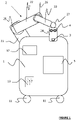
- the box 1 allows movement of the therapy equipment. It includes in particular wheels 11, a metal frame and an appropriate fairing so as to have a minimum of recesses in order to prevent dust or pathogenic elements from being able to lodge therein and prosper.
- the box 1 preferably comprises means of immobilization with respect to the ground to prevent its displacement during surgery.
- the box 1 carries the various elements of the therapy equipment - such as the arm 2 and the control device 5 - and comprises means for supplying them with electrical energy.
- the box 1 can also comprise display and input means 12 - such as a planning console - enabling the practitioner to control the therapy equipment and/or to follow the progress of the treatment applied to the eye. of the patient.
- display and input means 12 - such as a planning console - enabling the practitioner to control the therapy equipment and/or to follow the progress of the treatment applied to the eye. of the patient.
- the box 1 can include communication means 13 with or without wires for exchanging data with a remote workstation (not shown), or with the control device 5 if the latter is not integrated into the box 1.
- the arm 2 comprises several arm segments 21-24 connected by joints 25-27 (pivot or ball joints) to allow the rotational movement of the different segments 21-24 with respect to each other.
- Each joint 25-27 comprises a motorization and a brake.
- each brake is of the active type in the event of a power supply failure. This makes it possible to prevent any unexpected movement of the arm, for example in the event of a system failure or a power outage.
- the free end of the arm 2 comprises an immobilization member equipped with a suction ring capable of sucking on the ocular tissue and holding it firmly in position.
- the control device and method described below make it possible to automatically position the immobilization member on the ocular tissue to be treated.
- the arm 2 is for example a TX260L marketed by the company STAUBLI.
- the arm may include disengagement means to allow it to be moved manually, for example in the event of a failure or a power outage.
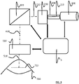
- the control device 5 makes it possible to control the shaping system 200, the optical scanning scanner 400 and the optical focusing system 500.
- the femtosecond laser 100 is capable of emitting an initial LASER beam in the form of pulses.
- femtosecond laser is meant a light source capable of emitting a LASER beam in the form of ultra-short pulses, the duration of which is between 1 femtosecond and 100 picoseconds, preferably between 1 and 1000 femtoseconds, in particular the order of a hundred femtoseconds.
- the shaping system 200 extends over the trajectory of the initial LASER beam 110 coming from the femtosecond laser 100. It makes it possible to transform the initial LASER beam 110 into a modulated LASER beam 210. More precisely, the shaping system makes it possible to modulate the phase of the LASER beam 110 to distribute the energy of the LASER beam in a plurality of points of impact in its focal plane, this plurality of points of impact defining a pattern. In other words, the shaping system 200 makes it possible to modulate the final energy distribution of the LASER beam in the focusing plane 710 corresponding to the cutting plane of the tissue 700.
- the shaping system 200 therefore makes it possible, from a LASER beam Gaussian generating a single point of impact, and by means of the phase mask, to distribute its energy by phase modulation so as to simultaneously generate several points of impact in its focal plane from a single LASER beam placed in form by phase modulation (a single beam upstream and downstream of the SLM).
- the optical coupler 300 makes it possible to transmit the LASER beam 110 from the femtosecond laser 100 to the shaping system 200. It advantageously comprises an optical fiber, in particular a photonic crystal fiber (or “PCF” , acronym for the English expression -Saxon "Photonic-Crystal Fiber” ) with hollow heart.
- a hollow-core photonic crystal fiber is an optical fiber that essentially guides light inside a hollow region (the core of the fiber), so that only a minor portion of the optical power travels through the material of solid fiber (typically a glass).
- the attractions of photonic crystal fibers at The hollow heart are mainly that the primary guidance in the hollow region minimizes the nonlinear effects of the modulated LASER beam and allows a high damage threshold.
- the hollow region of the hollow-core photonic crystal fiber can be put under vacuum to limit the propagation losses of the LASER beam coming from the femtosecond laser 100.
- the optical coupler 300 comprises first and second link cells sealed to each end of the hollow-core photonic crystal fiber. These link cells are connected to a vacuum pump P integrated into the box 1 to place the hollow core of the optical fiber under vacuum by pumping at the level of the link cells. The fact of performing vacuum pumping at each end of the optical fiber 31 facilitates the vacuuming of the hollow heart over the entire length of the optical fiber 31.
- the scanning optical scanner 400 directs the modulated LASER beam 210 to move the pattern along a path of movement predefined by the user in a plane of focus 710.
- the optical focusing system 500 makes it possible to move the focusing plane 710 - corresponding to the cutting plane - of the deflected LASER beam 410 coming from the optical scanning scanner 400.
- the shaping system 200, the optical scanning scanner 400 and the optical focusing system 500 can be mounted in a compartment fixed to the end 24 of the arm, while the femtosecond laser can be integrated into the box 1, the optical coupler 300 extending between the box 1 and the end segment 24 to propagate the initial laser beam 110 between the femtosecond laser 100 and the shaping system 200.
- the force sensor 3 makes it possible to detect mechanical forces generated in opposition to a movement of the arm 2, these forces reflecting the presence of an obstacle and possibly corresponding to the obtaining of a contact between the end of the arm 2 and the eye tissue.
- Force sensor 3 can be mounted on end segment 24 of arm 2.
- the force sensor 3 is of a type known per se to those skilled in the art. It is capable of sensing and measuring compression and traction forces applied along the longitudinal axis of the end segment 24 of the arm 2. It comprises one (or more) strain gauges mounted on the segment d end 24 of arm 2.
- Each mechanical force measured by the force sensor 3 is transmitted to the control device 5.
- the control device When the value of the mechanical force measured is greater than a threshold value, the control device performs one or more predetermined actions (generation of an immobilization instruction for the arm, command to issue a visual stimulus on means of display and input 12, and/or an auditory stimulus on a loudspeaker integrated into the box, etc.).
- the acquisition system 4 makes it possible to acquire measurement torques used to control the movement of the arm 2 relative to the ocular tissue to be treated.
- Each measurement pair includes one (or more) image(s) of an area located opposite the free end of arm 2.
- the acquisition system 4 can comprise an image acquisition unit of OCT (optical coherence tomography) or Scheimpflug (mapping in visible light) or UBM (Ultrasonic Bio Microscopy) type.
- OCT optical coherence tomography
- Scheimpflug mimpflug
- UBM Ultrasonic Bio Microscopy
- Such an image acquisition unit can be mounted on the end segment 24 of the arm 2, for example upstream of the optical scanning scanner 400.
- This image acquisition unit is arranged so as to have a sufficiently wide acquisition field (for example observing a perimeter P corresponding to a square of side 50 cm at a distance of 30 cm) in order to be able to identify the ocular tissue in this acquisition field.
- the image acquisition unit can be equipped with lighting means (coaxial or not) in order to facilitate recognition of the ocular tissue.
- Each measurement pair also includes one (or more) signal(s) representative(s) of a distance between the free end of the arm 2 and the ocular tissue.
- the acquisition system 4 may comprise a laser ranging unit, or an ultrasound ranging unit, either or an image analysis ranging unit, or by any other equivalent device known to those skilled in the art. loom capable of acquiring a signal representative of a distance between the free end of the arm 2 and the object located opposite this end.
- a telemetry unit can also be mounted on the end segment 24 of the arm 2.
- the control device 5 is connected to these different elements via one (or more) communication bus allowing the transmission of control signals, and the reception of acquisition data from the force sensor 3, from the system acquisition 4, etc.
- the control device 5 can be composed of one (or more) workstation(s), and/or of one (or more) computer(s).
- the control device 5 comprises a processor programmed to allow the control of the various elements of the therapy device, and to allow the processing of the signals acquired by the force sensor 3 and the acquisition system 4.
- the control means make it possible to activate the acquisition system 4 to acquire a plurality of measurement pairs successively over time. More precisely, after each transmission of an immobilization instruction by the servo-control means, the control means transmit an activation signal of the acquisition system for the acquisition of a new measurement torque. This new measurement torque is processed by the processing means in order to update the difference between the current position of the end of the arm and its desired final position.
- the processing means are able, from each measurement pair acquired, to detect the three-dimensional position of the ocular tissue and the three-dimensional position of the end of the arm.
- the three-dimensional position of the free end of the arm is known by construction.
- the three-dimensional position of the ocular tissue is obtained by calculation from the measurement torque from the acquisition system 4.
- the processing means are capable of identify the ocular tissue, its two-dimensional position and its center by recognizing a shape close to a typical morphology of an eye (three concentric circles: a white circle (the sclera), in the center of which is a colored circle (the iris ) in the center of which is a black circle (the pupil)).
- the third coordinate necessary for estimating the three-dimensional position of the ocular tissue is deduced from the signal acquired by the telemetry unit, this signal being representative of the distance between the free end of the arm and the ocular tissue.
- the servo means are programmed to implement a servo loop in the XY plane and a servo loop in the Z direction.
- the servo-control means of the control device 5 are able to generate a plurality of successive movement instructions to move the free end of the arm from the initial deployed position to the desired final position in which the immobilization member is centered and in contact with the ocular tissue to be treated.
- the servo-control means generate a plurality of successive elementary displacement instructions to bring the end of the arm in the desired final position.
- the servo means Between each emission of an elementary movement instruction, the servo means generate an immobilization instruction, and the control means emit an activation signal of the acquisition system 4 in order to acquire a new measurement torque. This makes it possible to check throughout the movement of the arm 2 that its end approaches the desired final position, and to take account of any unexpected movement of the patient's head (in which case the desired final position is updated) .
- the therapy device will be positioned on the same location each time it is used. In this way, the relative position of each patient with respect to the machine and in particular of his head and his eyes, is known with an acceptable margin of error, which can go up to 20 centimeters.
- the control device 5 controls the positioning of the end of the arm (by default and before the iterations necessary to obtain perfect centering) in the middle of the perimeter P. This position corresponds to the initial deployed position.
- the centering and contacting of the immobilizing member on the ocular tissue is carried out as follows.
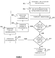
- control device 5 commands the deployment of the arm 2 (step 801).
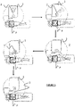
- Arm 2 moves automatically (as shown in the first four steps of the figure 5 ) so as to position the free end of the arm 2 at the center of the perimeter P (initial deployed position).
- control means of the control device 5 emit an activation signal of the acquisition system 4.
- the acquisition system 4 acquires an image and a signal representative of the distance between the end of the arm and the tissue ocular.
- the processing means receive the measurement torque acquired by the acquisition system 4 and process it (step 803).
- the servo means generate an immobilization instruction (step 806) for the arm 2 and the preceding steps (activation of the acquisition system 4, processing of the torque measurement, etc.) are repeated until the desired final horizontal position in XY is reached by the free end of arm 2.
- the Z servo loop can be implemented.
- the processing means of the control device 5 process the signal representative of a vertical distance along the Z axis (step 803), and compare (step 807) the current vertical position with the desired final vertical position.
- the servo-control means generate an immobilization instruction (step 809) of the arm 2 and the preceding steps are repeated, including the steps of the servo-control loop in XY, in order to verify that the current horizontal position always corresponds to the desired final horizontal position.
- the control device 5 makes it possible to position the free end of the arm precisely and centered. This free end carries the various working components allowing the treatment of the ocular tissue.
- the sequence of the different stages illustrated in figure 4 can be controlled using a foot control, and/or using a voice command and/or using a touchscreen or non-touch man-machine interface.
- the invention described above makes it possible in a few seconds to automatically position on the eye of a patient, a member for immobilizing the eyeball, without human intervention, in a rapid, precise and repeatable manner. Its performance is independent of the environment, in order to gain in precision, to make the gesture reproducible regardless of the patient or the operator, and to save time by relieving the operator of a task with low added value. .
- the invention also makes it possible to provide more safety and therefore to reduce the risk incurred by the patient at the time of the intervention.
- the immobilization member was mounted on the free end of the robotic arm.
- the immobilization member can be separated from the robotic arm.
- the immobilization member is positioned on the patient's eye prior to the movement of the robotic arm, and the desired final position corresponds to the contacting of the free end of the robotic arm with a face of the immobilization member opposite the surface of the immobilization member in contact with the eye. Accordingly, all such modifications are intended to be incorporated within the scope of the appended claims.
Landscapes
- Health & Medical Sciences (AREA)
- Surgery (AREA)
- Life Sciences & Earth Sciences (AREA)
- Engineering & Computer Science (AREA)
- General Health & Medical Sciences (AREA)
- Biomedical Technology (AREA)
- Heart & Thoracic Surgery (AREA)
- Animal Behavior & Ethology (AREA)
- Nuclear Medicine, Radiotherapy & Molecular Imaging (AREA)
- Public Health (AREA)
- Veterinary Medicine (AREA)
- Physics & Mathematics (AREA)
- Optics & Photonics (AREA)
- Medical Informatics (AREA)
- Molecular Biology (AREA)
- Ophthalmology & Optometry (AREA)
- Vascular Medicine (AREA)
- Robotics (AREA)
- Oral & Maxillofacial Surgery (AREA)
- Pathology (AREA)
- Electromagnetism (AREA)
- Otolaryngology (AREA)
- Manipulator (AREA)
- Laser Surgery Devices (AREA)
- Surgical Instruments (AREA)
- Prostheses (AREA)
Applications Claiming Priority (2)
| Application Number | Priority Date | Filing Date | Title |
|---|---|---|---|
| FR1850578A FR3076994B1 (fr) | 2018-01-25 | 2018-01-25 | Dispositif et procede de controle du deplacement d'un appareil de therapie oculaire incluant un bras support articule |
| PCT/EP2019/051876 WO2019145487A1 (fr) | 2018-01-25 | 2019-01-25 | Dispositif et procede de controle du deplacement d'un appareil de therapie oculaire incluant un bras support articule |
Publications (2)
| Publication Number | Publication Date |
|---|---|
| EP3743006A1 EP3743006A1 (fr) | 2020-12-02 |
| EP3743006B1 true EP3743006B1 (fr) | 2022-10-05 |
Family
ID=62683278
Family Applications (1)
| Application Number | Title | Priority Date | Filing Date |
|---|---|---|---|
| EP19701128.1A Active EP3743006B1 (fr) | 2018-01-25 | 2019-01-25 | Dispositif et procede de controle du deplacement d'un appareil de therapie oculaire incluant un bras support articule |
Country Status (11)
| Country | Link |
|---|---|
| US (1) | US20210038426A1 (enExample) |
| EP (1) | EP3743006B1 (enExample) |
| JP (1) | JP7268034B2 (enExample) |
| CN (1) | CN111801065B (enExample) |
| CA (1) | CA3089449A1 (enExample) |
| ES (1) | ES2934890T3 (enExample) |
| FR (1) | FR3076994B1 (enExample) |
| HU (1) | HUE060853T2 (enExample) |
| IL (1) | IL275887B2 (enExample) |
| PL (1) | PL3743006T3 (enExample) |
| WO (1) | WO2019145487A1 (enExample) |
Families Citing this family (14)
| Publication number | Priority date | Publication date | Assignee | Title |
|---|---|---|---|---|
| DE102018201612A1 (de) * | 2018-02-02 | 2019-08-08 | Carl Zeiss Industrielle Messtechnik Gmbh | Verfahren und Vorrichtung zur Erzeugung eines Steuersignals, Markeranordnung und steuerbares System |
| FR3098710B1 (fr) | 2019-07-19 | 2021-12-31 | Keranova | Appareil de decoupe a coupleur optique incluant un correcteur de polarisation |
| DE102019219122A1 (de) | 2019-09-10 | 2021-03-11 | Carl Zeiss Meditec Ag | Positioniereinrichtung |
| EP4034015B1 (en) | 2019-09-29 | 2025-06-11 | IPCA - Instituto Politécnico do Cávado e do Ave | Device for laser skin treatment |
| JPWO2021206153A1 (enExample) * | 2020-04-10 | 2021-10-14 | ||
| FR3116194B1 (fr) | 2020-11-17 | 2024-04-05 | Centre Nat Rech Scient | Système de sécurisation d’un patient adapté à une chirurgie de l’œil |
| FR3122570B1 (fr) | 2021-05-06 | 2024-11-22 | Keranova | Interface de couplage entre une source l.a.s.e.r. et un tissu a traiter |
| CN113261920B (zh) * | 2021-05-10 | 2026-07-28 | 吉林大学第一医院 | 一种肢体组织微循环血液灌注状态监测评估系统 |
| CN113478491B (zh) * | 2021-09-07 | 2021-11-16 | 成都博恩思医学机器人有限公司 | 一种机械臂的摆位控制方法、系统、机器人及存储介质 |
| CN113729615B (zh) * | 2021-10-12 | 2023-01-13 | 中山大学中山眼科中心 | 具有手持式探头的光学相干断层成像设备 |
| CN113974966B (zh) * | 2021-12-09 | 2023-06-09 | 固安翌光科技有限公司 | 一种光疗眼罩 |
| US12565918B2 (en) * | 2022-11-23 | 2026-03-03 | VaiLase, Inc. | Mechanisms and methods with one-way braking to control movement of a head of a medical system relative to an anatomical site |
| US12599454B2 (en) * | 2022-11-23 | 2026-04-14 | Vialase, Inc. | Mechanisms and methods to control movement of a head of a medical system relative to an anatomical site |
| US12605280B2 (en) * | 2022-11-23 | 2026-04-21 | Vialase, Inc. | Mechanisms and methods with variable counterbalance to control movement and force of a head of a medical system at an anatomical site |
Family Cites Families (16)
| Publication number | Priority date | Publication date | Assignee | Title |
|---|---|---|---|---|
| CN1160530A (zh) * | 1995-10-27 | 1997-10-01 | Ir视力公司 | 利用红外激光射线剥离眼角膜的方法和装置 |
| JP3764004B2 (ja) * | 1999-08-31 | 2006-04-05 | 株式会社ニデック | 眼科装置 |
| US7390089B2 (en) * | 2005-02-25 | 2008-06-24 | 20/10 Perfect Vision Optische Geraete Gmbh | Device and method for aligning an eye with a surgical laser |
| US9393068B1 (en) * | 2009-05-08 | 2016-07-19 | St. Jude Medical International Holding S.À R.L. | Method for predicting the probability of steam pop in RF ablation therapy |
| CN102834077B (zh) * | 2010-04-08 | 2015-04-01 | 爱尔康研究有限公司 | 患者眼睛水平触摸控制 |
| JP5218470B2 (ja) * | 2010-04-28 | 2013-06-26 | 株式会社安川電機 | ロボットの作業成否判定装置、および方法 |
| WO2015035354A1 (en) * | 2013-09-09 | 2015-03-12 | The Cleveland Clinic Foundation | Endoscope for tissue dissection and visualization |
| US10026015B2 (en) * | 2014-04-01 | 2018-07-17 | Case Western Reserve University | Imaging control to facilitate tracking objects and/or perform real-time intervention |
| JP6580679B2 (ja) * | 2014-09-25 | 2019-09-25 | オプティメディカ・コーポレイションOptimedica Corporation | 角膜トポグラフィー、瞬き検出、及び、レーザ眼手術システムのための方法及びシステム |
| JP2017534355A (ja) * | 2014-10-17 | 2017-11-24 | カール ツアイス メディテック アクチエンゲゼルシャフト | 短パルス・レーザ眼科手術用のシステムおよび方法 |
| JP2016193030A (ja) * | 2015-03-31 | 2016-11-17 | 株式会社ニデック | 眼科用レーザ手術装置および眼科手術制御プログラム |
| FI20155784A7 (fi) * | 2015-11-02 | 2017-05-03 | Cryotech Nordic Oue | Automatisoitu järjestelmä laser-avusteiseen dermatologiseen hoitoon ja ohjausmenetelmä |
| US10595955B2 (en) * | 2016-03-30 | 2020-03-24 | Sony Corporation | Control device, control method, and microscope device for operation |
| CN109069213B (zh) * | 2016-03-31 | 2022-12-27 | 皇家飞利浦有限公司 | 用于肿瘤抽吸的图像引导的机器人系统 |
| EP4193975B1 (en) * | 2016-04-05 | 2024-12-04 | AMO Development, LLC | Eye docking for laser eye surgery |
| DE102016206535A1 (de) * | 2016-04-19 | 2017-10-19 | Carl Zeiss Meditec Ag | Behandlungssystem für ophthalmologische Zwecke mit Überlastungsschutz |
-
2018
- 2018-01-25 FR FR1850578A patent/FR3076994B1/fr active Active
-
2019
- 2019-01-25 US US16/964,229 patent/US20210038426A1/en not_active Abandoned
- 2019-01-25 JP JP2020538897A patent/JP7268034B2/ja active Active
- 2019-01-25 CA CA3089449A patent/CA3089449A1/fr active Pending
- 2019-01-25 PL PL19701128.1T patent/PL3743006T3/pl unknown
- 2019-01-25 CN CN201980009760.XA patent/CN111801065B/zh active Active
- 2019-01-25 IL IL275887A patent/IL275887B2/en unknown
- 2019-01-25 ES ES19701128T patent/ES2934890T3/es active Active
- 2019-01-25 EP EP19701128.1A patent/EP3743006B1/fr active Active
- 2019-01-25 WO PCT/EP2019/051876 patent/WO2019145487A1/fr not_active Ceased
- 2019-01-25 HU HUE19701128A patent/HUE060853T2/hu unknown
Also Published As
| Publication number | Publication date |
|---|---|
| FR3076994B1 (fr) | 2022-03-11 |
| CN111801065B (zh) | 2023-08-11 |
| US20210038426A1 (en) | 2021-02-11 |
| RU2020128145A3 (enExample) | 2022-03-17 |
| WO2019145487A1 (fr) | 2019-08-01 |
| EP3743006A1 (fr) | 2020-12-02 |
| IL275887B2 (en) | 2024-02-01 |
| BR112020013859A2 (pt) | 2020-12-01 |
| CN111801065A (zh) | 2020-10-20 |
| CA3089449A1 (fr) | 2019-08-01 |
| JP2021511120A (ja) | 2021-05-06 |
| RU2020128145A (ru) | 2022-02-25 |
| JP7268034B2 (ja) | 2023-05-02 |
| IL275887B1 (en) | 2023-10-01 |
| IL275887A (en) | 2020-08-31 |
| FR3076994A1 (fr) | 2019-07-26 |
| PL3743006T3 (pl) | 2023-03-20 |
| ES2934890T3 (es) | 2023-02-27 |
| HUE060853T2 (hu) | 2023-04-28 |
Similar Documents
| Publication | Publication Date | Title |
|---|---|---|
| WO2019145487A1 (fr) | Dispositif et procede de controle du deplacement d'un appareil de therapie oculaire incluant un bras support articule | |
| US12303432B2 (en) | Ophthalmological imaging and laser delivery device, system and methods | |
| EP3146893B1 (en) | Apparatus for precision depth measurement | |
| KR101255797B1 (ko) | 안과 굴절교정 레이저 수술 장치, 이 장치용 제어 프로그램을 저장한 기계적으로 독취 가능한 데이타 매체 및 제어 프로그램을 생성하는 방법 | |
| EP1858460B1 (en) | Device and method for aligning an eye with a surgical laser | |
| CN102105122B (zh) | 用于眼科激光手术尤其是屈光激光手术的装置 | |
| JP2021511120A5 (enExample) | ||
| JP7817935B2 (ja) | 直接レーザ線維柱帯形成方法及び装置 | |
| US10548470B2 (en) | Image processing method and system for edge detection and laser eye surgery system incorporating the same | |
| CN109152659A (zh) | 眼科手术方法 | |
| CN116997308A (zh) | 用于改变眼睛颜色的激光系统和方法 | |
| US11013407B2 (en) | Intraocular pressure measurement for an eye docked to a laser system | |
| JP5902830B2 (ja) | 屈折レーザーの焦点深度を決定する画像処理方法 | |
| FR3108840A1 (fr) | Appareil de chirurgie ophtalmologique | |
| CN110234301B (zh) | 飞秒激光器的单阶段对接 | |
| RU2775140C2 (ru) | Устройство и способ для контроля перемещения аппарата глазной терапии | |
| WO2019207253A1 (fr) | Systeme de photocoagulation laser d'une retine | |
| BR112020013859B1 (pt) | Dispositivo de monitoramento para monitorar o movimento de um dispositivo de terapia ocular |
Legal Events
| Date | Code | Title | Description |
|---|---|---|---|
| STAA | Information on the status of an ep patent application or granted ep patent |
Free format text: STATUS: UNKNOWN |
|
| STAA | Information on the status of an ep patent application or granted ep patent |
Free format text: STATUS: THE INTERNATIONAL PUBLICATION HAS BEEN MADE |
|
| PUAI | Public reference made under article 153(3) epc to a published international application that has entered the european phase |
Free format text: ORIGINAL CODE: 0009012 |
|
| STAA | Information on the status of an ep patent application or granted ep patent |
Free format text: STATUS: REQUEST FOR EXAMINATION WAS MADE |
|
| 17P | Request for examination filed |
Effective date: 20200729 |
|
| AK | Designated contracting states |
Kind code of ref document: A1 Designated state(s): AL AT BE BG CH CY CZ DE DK EE ES FI FR GB GR HR HU IE IS IT LI LT LU LV MC MK MT NL NO PL PT RO RS SE SI SK SM TR |
|
| AX | Request for extension of the european patent |
Extension state: BA ME |
|
| DAV | Request for validation of the european patent (deleted) | ||
| DAX | Request for extension of the european patent (deleted) | ||
| REG | Reference to a national code |
Ref country code: DE Ref legal event code: R079 Ref document number: 602019020259 Country of ref document: DE Free format text: PREVIOUS MAIN CLASS: A61B0090500000 Ipc: A61F0009008000 |
|
| GRAP | Despatch of communication of intention to grant a patent |
Free format text: ORIGINAL CODE: EPIDOSNIGR1 |
|
| STAA | Information on the status of an ep patent application or granted ep patent |
Free format text: STATUS: GRANT OF PATENT IS INTENDED |
|
| RIC1 | Information provided on ipc code assigned before grant |
Ipc: A61B 34/30 20160101ALN20220420BHEP Ipc: A61B 18/22 20060101ALN20220420BHEP Ipc: A61B 90/00 20160101ALN20220420BHEP Ipc: A61B 18/20 20060101ALN20220420BHEP Ipc: A61F 9/009 20060101ALI20220420BHEP Ipc: A61B 90/50 20160101ALI20220420BHEP Ipc: A61F 9/008 20060101AFI20220420BHEP |
|
| INTG | Intention to grant announced |
Effective date: 20220518 |
|
| GRAS | Grant fee paid |
Free format text: ORIGINAL CODE: EPIDOSNIGR3 |
|
| GRAA | (expected) grant |
Free format text: ORIGINAL CODE: 0009210 |
|
| STAA | Information on the status of an ep patent application or granted ep patent |
Free format text: STATUS: THE PATENT HAS BEEN GRANTED |
|
| AK | Designated contracting states |
Kind code of ref document: B1 Designated state(s): AL AT BE BG CH CY CZ DE DK EE ES FI FR GB GR HR HU IE IS IT LI LT LU LV MC MK MT NL NO PL PT RO RS SE SI SK SM TR |
|
| REG | Reference to a national code |
Ref country code: GB Ref legal event code: FG4D Free format text: NOT ENGLISH |
|
| REG | Reference to a national code |
Ref country code: CH Ref legal event code: EP |
|
| REG | Reference to a national code |
Ref country code: AT Ref legal event code: REF Ref document number: 1522291 Country of ref document: AT Kind code of ref document: T Effective date: 20221015 |
|
| REG | Reference to a national code |
Ref country code: DE Ref legal event code: R096 Ref document number: 602019020259 Country of ref document: DE |
|
| REG | Reference to a national code |
Ref country code: IE Ref legal event code: FG4D Free format text: LANGUAGE OF EP DOCUMENT: FRENCH |
|
| REG | Reference to a national code |
Ref country code: NL Ref legal event code: FP |
|
| REG | Reference to a national code |
Ref country code: LT Ref legal event code: MG9D |
|
| REG | Reference to a national code |
Ref country code: ES Ref legal event code: FG2A Ref document number: 2934890 Country of ref document: ES Kind code of ref document: T3 Effective date: 20230227 |
|
| PG25 | Lapsed in a contracting state [announced via postgrant information from national office to epo] |
Ref country code: SE Free format text: LAPSE BECAUSE OF FAILURE TO SUBMIT A TRANSLATION OF THE DESCRIPTION OR TO PAY THE FEE WITHIN THE PRESCRIBED TIME-LIMIT Effective date: 20221005 Ref country code: PT Free format text: LAPSE BECAUSE OF FAILURE TO SUBMIT A TRANSLATION OF THE DESCRIPTION OR TO PAY THE FEE WITHIN THE PRESCRIBED TIME-LIMIT Effective date: 20230206 Ref country code: NO Free format text: LAPSE BECAUSE OF FAILURE TO SUBMIT A TRANSLATION OF THE DESCRIPTION OR TO PAY THE FEE WITHIN THE PRESCRIBED TIME-LIMIT Effective date: 20230105 Ref country code: LT Free format text: LAPSE BECAUSE OF FAILURE TO SUBMIT A TRANSLATION OF THE DESCRIPTION OR TO PAY THE FEE WITHIN THE PRESCRIBED TIME-LIMIT Effective date: 20221005 Ref country code: FI Free format text: LAPSE BECAUSE OF FAILURE TO SUBMIT A TRANSLATION OF THE DESCRIPTION OR TO PAY THE FEE WITHIN THE PRESCRIBED TIME-LIMIT Effective date: 20221005 |
|
| REG | Reference to a national code |
Ref country code: HU Ref legal event code: AG4A Ref document number: E060853 Country of ref document: HU |
|
| PG25 | Lapsed in a contracting state [announced via postgrant information from national office to epo] |
Ref country code: RS Free format text: LAPSE BECAUSE OF FAILURE TO SUBMIT A TRANSLATION OF THE DESCRIPTION OR TO PAY THE FEE WITHIN THE PRESCRIBED TIME-LIMIT Effective date: 20221005 Ref country code: LV Free format text: LAPSE BECAUSE OF FAILURE TO SUBMIT A TRANSLATION OF THE DESCRIPTION OR TO PAY THE FEE WITHIN THE PRESCRIBED TIME-LIMIT Effective date: 20221005 Ref country code: IS Free format text: LAPSE BECAUSE OF FAILURE TO SUBMIT A TRANSLATION OF THE DESCRIPTION OR TO PAY THE FEE WITHIN THE PRESCRIBED TIME-LIMIT Effective date: 20230205 Ref country code: HR Free format text: LAPSE BECAUSE OF FAILURE TO SUBMIT A TRANSLATION OF THE DESCRIPTION OR TO PAY THE FEE WITHIN THE PRESCRIBED TIME-LIMIT Effective date: 20221005 Ref country code: GR Free format text: LAPSE BECAUSE OF FAILURE TO SUBMIT A TRANSLATION OF THE DESCRIPTION OR TO PAY THE FEE WITHIN THE PRESCRIBED TIME-LIMIT Effective date: 20230106 |
|
| P01 | Opt-out of the competence of the unified patent court (upc) registered |
Effective date: 20230329 |
|
| REG | Reference to a national code |
Ref country code: DE Ref legal event code: R097 Ref document number: 602019020259 Country of ref document: DE |
|
| PG25 | Lapsed in a contracting state [announced via postgrant information from national office to epo] |
Ref country code: SM Free format text: LAPSE BECAUSE OF FAILURE TO SUBMIT A TRANSLATION OF THE DESCRIPTION OR TO PAY THE FEE WITHIN THE PRESCRIBED TIME-LIMIT Effective date: 20221005 Ref country code: RO Free format text: LAPSE BECAUSE OF FAILURE TO SUBMIT A TRANSLATION OF THE DESCRIPTION OR TO PAY THE FEE WITHIN THE PRESCRIBED TIME-LIMIT Effective date: 20221005 Ref country code: EE Free format text: LAPSE BECAUSE OF FAILURE TO SUBMIT A TRANSLATION OF THE DESCRIPTION OR TO PAY THE FEE WITHIN THE PRESCRIBED TIME-LIMIT Effective date: 20221005 Ref country code: DK Free format text: LAPSE BECAUSE OF FAILURE TO SUBMIT A TRANSLATION OF THE DESCRIPTION OR TO PAY THE FEE WITHIN THE PRESCRIBED TIME-LIMIT Effective date: 20221005 |
|
| PLBE | No opposition filed within time limit |
Free format text: ORIGINAL CODE: 0009261 |
|
| STAA | Information on the status of an ep patent application or granted ep patent |
Free format text: STATUS: NO OPPOSITION FILED WITHIN TIME LIMIT |
|
| PG25 | Lapsed in a contracting state [announced via postgrant information from national office to epo] |
Ref country code: SK Free format text: LAPSE BECAUSE OF FAILURE TO SUBMIT A TRANSLATION OF THE DESCRIPTION OR TO PAY THE FEE WITHIN THE PRESCRIBED TIME-LIMIT Effective date: 20221005 Ref country code: AL Free format text: LAPSE BECAUSE OF FAILURE TO SUBMIT A TRANSLATION OF THE DESCRIPTION OR TO PAY THE FEE WITHIN THE PRESCRIBED TIME-LIMIT Effective date: 20221005 |
|
| 26N | No opposition filed |
Effective date: 20230706 |
|
| PG25 | Lapsed in a contracting state [announced via postgrant information from national office to epo] |
Ref country code: LU Free format text: LAPSE BECAUSE OF NON-PAYMENT OF DUE FEES Effective date: 20230125 |
|
| PG25 | Lapsed in a contracting state [announced via postgrant information from national office to epo] |
Ref country code: SI Free format text: LAPSE BECAUSE OF FAILURE TO SUBMIT A TRANSLATION OF THE DESCRIPTION OR TO PAY THE FEE WITHIN THE PRESCRIBED TIME-LIMIT Effective date: 20221005 |
|
| REG | Reference to a national code |
Ref country code: AT Ref legal event code: UEP Ref document number: 1522291 Country of ref document: AT Kind code of ref document: T Effective date: 20221005 |
|
| PG25 | Lapsed in a contracting state [announced via postgrant information from national office to epo] |
Ref country code: MC Free format text: LAPSE BECAUSE OF FAILURE TO SUBMIT A TRANSLATION OF THE DESCRIPTION OR TO PAY THE FEE WITHIN THE PRESCRIBED TIME-LIMIT Effective date: 20221005 |
|
| PG25 | Lapsed in a contracting state [announced via postgrant information from national office to epo] |
Ref country code: MC Free format text: LAPSE BECAUSE OF FAILURE TO SUBMIT A TRANSLATION OF THE DESCRIPTION OR TO PAY THE FEE WITHIN THE PRESCRIBED TIME-LIMIT Effective date: 20221005 |
|
| PG25 | Lapsed in a contracting state [announced via postgrant information from national office to epo] |
Ref country code: BG Free format text: LAPSE BECAUSE OF FAILURE TO SUBMIT A TRANSLATION OF THE DESCRIPTION OR TO PAY THE FEE WITHIN THE PRESCRIBED TIME-LIMIT Effective date: 20221005 |
|
| PG25 | Lapsed in a contracting state [announced via postgrant information from national office to epo] |
Ref country code: BG Free format text: LAPSE BECAUSE OF FAILURE TO SUBMIT A TRANSLATION OF THE DESCRIPTION OR TO PAY THE FEE WITHIN THE PRESCRIBED TIME-LIMIT Effective date: 20221005 |
|
| PGFP | Annual fee paid to national office [announced via postgrant information from national office to epo] |
Ref country code: NL Payment date: 20241224 Year of fee payment: 7 Ref country code: PL Payment date: 20241230 Year of fee payment: 7 |
|
| PGFP | Annual fee paid to national office [announced via postgrant information from national office to epo] |
Ref country code: IE Payment date: 20241219 Year of fee payment: 7 |
|
| PGFP | Annual fee paid to national office [announced via postgrant information from national office to epo] |
Ref country code: HU Payment date: 20241220 Year of fee payment: 7 |
|
| PGFP | Annual fee paid to national office [announced via postgrant information from national office to epo] |
Ref country code: AT Payment date: 20241219 Year of fee payment: 7 Ref country code: BE Payment date: 20250128 Year of fee payment: 7 |
|
| PGFP | Annual fee paid to national office [announced via postgrant information from national office to epo] |
Ref country code: CZ Payment date: 20250121 Year of fee payment: 7 |
|
| PGFP | Annual fee paid to national office [announced via postgrant information from national office to epo] |
Ref country code: TR Payment date: 20250124 Year of fee payment: 7 |
|
| PG25 | Lapsed in a contracting state [announced via postgrant information from national office to epo] |
Ref country code: CY Free format text: LAPSE BECAUSE OF FAILURE TO SUBMIT A TRANSLATION OF THE DESCRIPTION OR TO PAY THE FEE WITHIN THE PRESCRIBED TIME-LIMIT; INVALID AB INITIO Effective date: 20190125 |
|
| REG | Reference to a national code |
Ref country code: CH Ref legal event code: U11 Free format text: ST27 STATUS EVENT CODE: U-0-0-U10-U11 (AS PROVIDED BY THE NATIONAL OFFICE) Effective date: 20260201 |
|
| PGFP | Annual fee paid to national office [announced via postgrant information from national office to epo] |
Ref country code: GB Payment date: 20260127 Year of fee payment: 8 |
|
| PGFP | Annual fee paid to national office [announced via postgrant information from national office to epo] |
Ref country code: ES Payment date: 20260209 Year of fee payment: 8 |
|
| PGFP | Annual fee paid to national office [announced via postgrant information from national office to epo] |
Ref country code: DE Payment date: 20260114 Year of fee payment: 8 |
|
| PGFP | Annual fee paid to national office [announced via postgrant information from national office to epo] |
Ref country code: IT Payment date: 20260107 Year of fee payment: 8 |
|
| PGFP | Annual fee paid to national office [announced via postgrant information from national office to epo] |
Ref country code: FR Payment date: 20260128 Year of fee payment: 8 |
|
| PGFP | Annual fee paid to national office [announced via postgrant information from national office to epo] |
Ref country code: CH Payment date: 20260201 Year of fee payment: 8 |