EP3742055A1 - Haushaltsgerät und dessen objektivbaugruppe - Google Patents
Haushaltsgerät und dessen objektivbaugruppe Download PDFInfo
- Publication number
- EP3742055A1 EP3742055A1 EP20172349.1A EP20172349A EP3742055A1 EP 3742055 A1 EP3742055 A1 EP 3742055A1 EP 20172349 A EP20172349 A EP 20172349A EP 3742055 A1 EP3742055 A1 EP 3742055A1
- Authority
- EP
- European Patent Office
- Prior art keywords
- wall
- air
- lens
- air flow
- lens assembly
- Prior art date
- Legal status (The legal status is an assumption and is not a legal conclusion. Google has not performed a legal analysis and makes no representation as to the accuracy of the status listed.)
- Granted
Links
Images

Classifications
-
- F—MECHANICAL ENGINEERING; LIGHTING; HEATING; WEAPONS; BLASTING
- F24—HEATING; RANGES; VENTILATING
- F24C—DOMESTIC STOVES OR RANGES ; DETAILS OF DOMESTIC STOVES OR RANGES, OF GENERAL APPLICATION
- F24C15/00—Details
- F24C15/20—Removing cooking fumes
- F24C15/2021—Arrangement or mounting of control or safety systems
-
- G—PHYSICS
- G02—OPTICS
- G02B—OPTICAL ELEMENTS, SYSTEMS OR APPARATUS
- G02B27/00—Optical systems or apparatus not provided for by any of the groups G02B1/00 - G02B26/00, G02B30/00
- G02B27/0006—Optical systems or apparatus not provided for by any of the groups G02B1/00 - G02B26/00, G02B30/00 with means to keep optical surfaces clean, e.g. by preventing or removing dirt, stains, contamination, condensation
Definitions
- the present application relates to the household appliance sector, in particular to a lens assembly of a household appliance.
- a camera is attached to an extractor hood, with which images of a cooking process taking place below the extractor hood are recorded or movements of the user are recorded in order to generate a corresponding control command.
- a kitchen differs from other environments in that cooking creates haze, so the air inevitably contains fat, especially in the area of the cooker hood.
- the lens of the camera attached to the extractor hood is often loaded with grease, which has a negative effect on the recording effect.
- the lens arranged on a household appliance emits a lot of heat during operation, which must be effectively dissipated, which is also a problem that must be solved urgently.
- One embodiment of the present application relates to a lens assembly of a household appliance, which includes a lens, an air flow generating device, an air duct and a protective hood.
- the protective hood comprises an inner wall and an outer wall, an air flow channel being formed between the inner wall and the outer wall.
- An air outlet hole opening into the air flow channel is provided on the inner wall.
- the inner wall is ring-shaped and at least partially encloses the lens.
- an air flow generated by the air flow generation device enters the air flow channel after flowing out of the outlet of the air channel and then flows out through the air outlet hole in the inner wall. In this way, on the one hand, the adhesion of grease to the lens can be reduced and, on the other hand, heat dissipation can be supported.
- the air outlet hole in the inner wall is arranged in such a way that the air flow flowing out of the air outlet hole in the inner wall generates an air curtain in front of the lens. This helps reduce the adhesion of grease to the lens.
- the inner wall has the shape of a horn mouth. This makes it possible for the air flow flowing out of the air outlet hole in the inner wall to generate an air curtain in front of the lens.
- the inner wall has the shape of a truncated cone jacket. This makes it possible for the air flow flowing out of the air outlet hole in the inner wall to generate an air curtain in front of the lens.
- air outlet holes are provided, which are arranged one behind the other in the circumferential direction of the inner wall. This makes it possible for the air flow flowing out of the air outlet hole in the inner wall to generate an air curtain in front of the lens.
- the lens assembly further comprises a filter screen which is arranged in the air duct.
- a filter screen which is arranged in the air duct.
- the air flow generating device comprises a fan that is located in the air duct and is arranged between the filter screen and the outlet of the air duct.
- the objective is an image recording objective and / or a projection objective.
- the protective hood further comprises a fastening section which is designed for fastening the lens, the inner wall of the protective hood being connected at one end to the outer wall of the protective hood and at the other end to the fastening section, while the outer wall of the protective hood is connected at one end is connected to the inner wall of the protective hood and forms an air inlet opening at the other end, to which the outlet of the air duct is connected. It is thereby achieved that an air flow generated by the air flow generating device, after flowing out of the outlet of the air channel, first enters the air inlet opening and then into the air flow channel in order to then flow out through the air outlet hole of the inner wall.
- Another exemplary embodiment of the present application relates to a household appliance with a lens assembly according to one of the preceding exemplary embodiments.
- the household appliance is an extractor hood which is provided with an extractor hood, the protective hood and the lens being arranged on a bottom wall of the extractor hood, while the inlet of the air duct is located on an upper wall of the extractor hood.
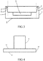
- the present application proposes an embodiment of an extractor hood that, as shown in FIG FIG 4 can be seen, comprises a housing 9, a vapor collection hood 10 and a lens assembly.
- the lens assembly is fixedly arranged on the vapor collection hood 10.
- the lens assembly is embedded in the vapor collection hood 10.
- This extractor hood is an upward suction hood, in which the extractor hood 10 is arranged hanging below the housing 9, so that the extractor hood as a whole has an inverted T-shape according to FIG FIG 4 Has.
- the lens assembly comprises a camera, a filter screen 1, an air flow generating device, an air duct and a protective hood 4.
- the camera comprises an objective 5.
- the filter screen 1 is arranged in the air duct. Specifically, the filter screen 1 is located at the inlet of the air duct.
- the air flow generating device comprises a fan 2, which is designed as a centrifugal fan and is arranged in the air duct. The fan 2 is located between the filter screen 1 and the outlet 3 of the air duct.
- the protective hood 4 comprises an inner wall 6, an outer wall 7 and a fastening section, an air flow channel 13 being formed between the inner wall 6 and the outer wall 7. As in FIG 2 is shown, a plurality of air outlet holes 8 opening into the air flow channel 13 are provided on the inner wall 6.
- the inner wall 6 is annular, has the shape of a horn mouth and surrounds the lens 5. Specifically, the inner wall 6 is designed in the shape of a truncated cone, ie the inner wall 6 has the shape of a truncated cone.
- FIG 3 shows a sectional view of the protective hood 4, in which the protective hood 4 is cut into two symmetrical parts by a corresponding sectional plane. In FIG 3 the air outlet holes 8 are not shown.
- FIG 3 it can be seen that the inner wall 6 the protective hood 4 is connected at one end to the outer wall 7 of the protective hood 4 and at the other end to the fastening section.
- the fastening section is designed for fastening the objective 5.
- the fastening section is provided with a receiving groove 14, one surface of the receiving groove 14 being used to attach the lens 5 (in the present exemplary embodiment the entire camera including the lens 5 is attached to this surface of the receiving groove 14), while the other, opposite surface the receiving groove 14 is used for introducing an air flow into the air flow channel 13, see in this regard FIG 3 .
- the outer wall 7 of the protective hood 4 is cylindrical, the outer wall 7 of the protective hood 4, as in FIG FIG 3 shown, is connected at one end to the inner wall 6 of the protective hood 4 and forms an air inlet opening 15 with the other end.
- the outer wall 7 of the protective hood 4 encloses both the fastening section and the inner wall 6 of the protective hood 4.
- the outlet 3 of the air duct connects to the air inlet opening 15 of the outer wall 7 of the protective hood 4 in such a way that an outlet from the outlet 3 of the The air flow exiting the air duct flows into the air inlet opening 15 in order to then only be able to flow out through the air outlet holes 8 of the inner wall 6.
- the air outlet holes 8 of the inner wall 6 are arranged such that the air flow flowing out of the air outlet holes 8 of the inner wall 6 generates an air curtain in front of the lens 5.
- the air flow generating device of the lens assembly generates an air flow during operation which, after flowing out of the outlet 3 of the air channel, enters the air flow channel 13 via the air inlet opening 15 and then flows out through the air outlet holes 8 of the inner wall 6, the direction of flow of the air flow in Essentially by the arrows in FIG 1 is shown.
- FIG 1 shows only a schematic representation of the mode of operation, in which the protective hood 4 is shown in a sectional view.
- air outlet holes 8 are provided, which are arranged one behind the other in the circumferential direction of the inner wall 6, that is to say all air outlet holes 8 are in total around the Lens 5 arranged around.
- FIG 2 it can be seen that all air outlet holes 8 are arranged from top to bottom in five circumferential rings in order to be able to generate an evenly distributed air curtain.
- the individual air outlet holes 8 are each designed as a round hole.
- the protective hood 4 is arranged on a bottom wall 12 of the vapor collecting hood 10 and the inlet of the air duct is arranged on a top wall 11 of the vapor collecting hood 10.
- the lens 5 is located on the bottom wall 12 of the extractor hood 10 and is oriented downwards in order to record images of a cooking process taking place on a cooking device arranged below the extractor hood and thus to create a cooking video. Furthermore, the lens 5 is suitable for recording an image of the haze produced during operation of the cooking appliance located below the extractor hood in order to determine the haze concentration.
- the air flow moves essentially downwards, as essentially indicated by the arrows in FIG FIG 1 is shown.
- the air outlet holes do not necessarily have to be circular, but can also be, for example, triangular, oval, five-pointed, star-shaped or square.
- the individual air outlet holes can also be arranged differently than in the present exemplary embodiment, insofar as this enables the object of the present embodiment to be achieved.
- the individual air outlet holes can be arranged uniformly distributed on the inner wall in any desired manner. It is also conceivable to replace the camera of the lens assembly with a projection device, the lens correspondingly having a projection function.
- the camera of the lens assembly can also be replaced by an image recording and projection device, the lens correspondingly having both an image recording function and a projection function.
- An axial fan can also be used as the fan.
- the fastening section can also be constructed differently than in the present exemplary embodiment, insofar as this is suitable for fastening the objective.
- the protective hood only comprises the inner wall and the outer wall, ie without a fastening section, and has the overall shape of a cylinder, the lens being arranged in the inner cavity of the cylindrical protective hood and the inner wall of the protective hood enclosing the lens.
- the air inlet opening via which the respective air flow is introduced into the air flow channel formed between the inner wall and the outer wall can be provided at one end of the protective hood or also on the outer wall of the protective hood.
- the design of the lens assembly disclosed in the previous embodiment is not limited to use in upward extraction hoods, but can also be used in other types of extractor hoods, such as side extraction hoods or both side extraction and upward extraction hoods.
- the configuration of the lens assembly disclosed in the previous exemplary embodiment can also be used in other household appliances, such as ovens, steamers, combination cookers or refrigerators, in addition to in extractor hoods.
Landscapes
- Physics & Mathematics (AREA)
- Engineering & Computer Science (AREA)
- General Physics & Mathematics (AREA)
- Optics & Photonics (AREA)
- Chemical & Material Sciences (AREA)
- Combustion & Propulsion (AREA)
- Mechanical Engineering (AREA)
- General Engineering & Computer Science (AREA)
- Blocking Light For Cameras (AREA)
Abstract
Description
- Die vorliegende Anmeldung bezieht sich auf den Haushaltsgerätebereich, insbesondere auf eine Objektivbaugruppe eines Haushaltsgeräts.
- Aufgrund des wissenschaftlichen und technischen Fortschritts besteht im Haushaltsgerätebereich die Tendenz zur Intellektualisierung. Dabei sind viele Haushaltsgeräte mit einem Objektiv zur Bildaufnahme oder zur Projizierung versehen. So ist z.B. an einer Dunstabzugshaube eine Kamera angebracht, mit der Bilder eines unterhalb der Dunstabzugshaube stattfindenden Kochvorgangs aufgenommen oder Bewegungen des Benutzers erfasst werden, um einen entsprechenden Steuerbefehl zu erzeugen. Allerdings unterscheidet sich eine Küche dadurch von anderen Umgebungen, dass beim Kochen Dunst entsteht, so dass in der Luft unvermeidlich Fett enthalten ist, insbesondere im Bereich der Dunstabzugshaube. Dabei ist das Objektiv der an der Dunstabzugshaube angebrachten Kamera oft mit dem Fett belastet, was sich negativ auf den Aufnahmeeffekt auswirkt. Zudem gibt das an einem Haushaltsgerät angeordnete Objektiv beim Betrieb viel Wärme ab, die effektiv abgeführt werden muss, was auch ein dringend zu lösendes Problem darstellt.
- Mit der obenstehenden Beschreibung des Stands der Technik wird nicht eingestanden, dass dieser Stand der Technik bereits vor dem Anmeldetag der vorliegenden Anmeldung für die durchschnittlichen Fachleuten auf diesem Gebiet allgemein bekannt ist, es sei denn, dass ausreichende Nachweise dafür vorliegen.
- Ausgehend von zumindest einem der oben erwähnten Probleme ist es eine Aufgabe der Ausführungsbeispiele der vorliegenden Anmeldung, ein verbessertes Haushaltsgerät und eine zugehörige Objektivbaugruppe vorzuschlagen.
- Ein Ausführungsbeispiel der vorliegenden Anmeldung betrifft eine Objektivbaugruppe eines Haushaltsgeräts, die ein Objektiv, eine Luftstromerzeugungsvorrichtung, einen Luftkanal und eine Schutzhaube umfasst. Die Schutzhaube umfasst eine Innenwand und eine Außenwand, wobei zwischen der Innenwand und der Außenwand ein Luftstromkanal ausgebildet ist. An der Innenwand ist ein in den Luftstromkanal mündendes Luftaustrittsloch vorgesehen. Die Innenwand ist ringförmig ausgebildet und umschließt zumindest teilweise das Objektiv. Dabei tritt ein durch die Luftstromerzeugungsvorrichtung erzeugter Luftstrom nach Herausströmen aus dem Auslass des Luftkanals in den Luftstromkanal ein und strömt anschließend durch das Luftaustrittsloch der Innenwand aus. Auf diese Weise kann zum einen die Anhaftung von Fett an dem Objektiv reduziert und zum anderen die Wärmeabführung unterstützt werden.
- In einem möglichen Ausführungsbeispiel ist das Luftaustrittsloch der Innenwand so angeordnet, dass der aus dem Luftaustrittsloch der Innenwand herausströmende Luftstrom einen Luftvorhang vor dem Objektiv erzeugt. Dies trägt zur Reduzierung der Anhaftung von Fett an dem Objektiv bei.
- In einem möglichen Ausführungsbeispiel hat die Innenwand die Form eines Hornmunds. Dadurch wird es ermöglicht, dass der aus dem Luftaustrittsloch der Innenwand herausströmende Luftstrom einen Luftvorhang vor dem Objektiv erzeugt.
- In einem möglichen Ausführungsbeispiel hat die Innenwand die Form eines Kegelstumpfmantels. Dadurch wird es ermöglicht, dass der aus dem Luftaustrittsloch der Innenwand herausströmende Luftstrom einen Luftvorhang vor dem Objektiv erzeugt.
- In einem möglichen Ausführungsbeispiel sind mehrere Luftaustrittslöcher vorgesehen, die in Umfangsrichtung der Innenwand hintereinander angeordnet sind. Dadurch wird es ermöglicht, dass der aus dem Luftaustrittsloch der Innenwand herausströmende Luftstrom einen Luftvorhang vor dem Objektiv erzeugt.
- In einem möglichen Ausführungsbeispiel umfasst die Objektivbaugruppe ferner ein Filtersieb, das in dem Luftkanal angeordnet ist. Durch das Vorsehen des Filtersiebs kann die Sauberkeit des aus dem Luftaustrittsloch der Innenwand herausströmenden Luftstroms erhöht werden, was zur Reduzierung der Anhaftung von Fett an dem Objektiv beiträgt.
- In einem möglichen Ausführungsbeispiel umfasst die Luftstromerzeugungsvorrichtung ein Gebläse, das sich in dem Luftkanal befindet und zwischen dem Filtersieb und dem Auslass des Luftkanals angeordnet ist.
- In einem möglichen Ausführungsbeispiel handelt es sich bei dem Objektiv um ein Bildaufnahmeobjektiv und/oder um ein Projektionsobjektiv.
- In einem möglichen Ausführungsbeispiel umfasst die Schutzhaube ferner einen Befestigungsabschnitt, der zum Befestigen des Objektivs eingerichtet ist, wobei die Innenwand der Schutzhaube an einem Ende mit der Außenwand der Schutzhaube und am anderen Ende mit dem Befestigungsabschnitt verbunden ist, während die Außenwand der Schutzhaube an einem Ende mit der Innenwand der Schutzhaube verbunden ist und mit dem anderen Ende eine Lufteintrittsöffnung bildet, an die sich der Auslass des Luftkanals anschließt. Dadurch wird erreicht, dass ein durch die Luftstromerzeugungsvorrichtung erzeugter Luftstrom nach Herausströmen aus dem Auslass des Luftkanals zunächst in die Lufteintrittsöffnung und dann in den Luftstromkanal eintritt, um anschließend durch das Luftaustrittsloch der Innenwand auszuströmen.
- Ein weiteres Ausführungsbeispiel der vorliegenden Anmeldung betrifft ein Haushaltsgerät mit einer Objektivbaugruppe gemäß einem der vorangehenden Ausführungsbeispiele.
- In einem möglichen Ausführungsbeispiel handelt es sich bei dem Haushaltsgerät um eine Dunstabzugshaube, die mit einer Dunstauffanghaube versehen ist, wobei die Schutzhaube und das Objektiv an einer Bodenwand der Dunstauffanghaube angeordnet sind, während sich der Einlass des Luftkanals an einer Oberwand der Dunstauffanghaube befindet.
- Die obenstehenden Ausgestaltungen der vorliegenden Anmeldung dienen nicht zur Beschreibung aller möglicher Ausführungsformen der vorliegenden Anmeldung. In der ganzen Anmeldung werden mehrere Beispiele zur Anleitung aufgezählt, welche bei verschiedenen möglichen Kombinationen verwendet werden können.
- Die nachstehenden Zeichnungen stellen keine Einschränkung des Rahmens der vorliegenden Anmeldung dar, sondern dienen lediglich zur schematischen Darlegung und Erläuterung der vorliegenden Anmeldung. Dabei zeigen:
-
FIG 1 in schematischer Darstellung die Funktionsweise einer Objektivbaugruppe eines Ausführungsbeispiels einer Dunstabzugshaube gemäß der vorliegenden Anmeldung, -
FIG 2 in schematischer Darstellung die Struktur einer Schutzhaube einer Objektivbaugruppe eines Ausführungsbeispiels einer Dunstabzugshaube gemäß der vorliegenden Anmeldung, -
FIG 3 eine Schnittansicht der Schutzhaube gemäßFIG 2 und -
FIG 4 in schematischer Darstellung die Struktur eines Ausführungsbeispiels einer Dunstabzugshaube gemäß der vorliegenden Anmeldung. -
- 1
- Filtersieb
- 2
- Gebläse
- 3
- Auslass eines Luftkanals
- 4
- Schutzhaube
- 5
- Objektiv
- 6
- Innenwand der Schutzhaube
- 7
- Außenwand der Schutzhaube
- 8
- Luftaustrittsloch
- 9
- Gehäuse
- 10
- Dunstauffanghaube
- 11
- Oberwand der Dunstauffanghaube
- 12
- Bodenwand der Dunstauffanghaube
- 13
- Luftstromkanal
- 14
- Aufnahmenut
- 15
- Lufteintrittsöffnung
- Zum besseren Verständnis der Aufgabe, der Ausgestaltungen und der vorteilhaften Wirkungen der vorliegenden Anmeldung wird diese im Folgenden anhand bevorzugter Ausführungsbeispiele unter Bezugnahme auf die beigefügten Zeichnungen näher beschrieben.
- Die vorliegende Anmeldung schlägt ein Ausführungsbeispiel einer Dunstabzugshaube vor, das, wie in
FIG 4 erkennbar, ein Gehäuse 9, eine Dunstauffanghaube 10 und eine Objektivbaugruppe umfasst. Hierbei ist die Objektivbaugruppe fest an der Dunstauffanghaube 10 angeordnet. Konkret ist die Objektivbaugruppe in der Dunstauffanghaube 10 eingebettet. Bei dieser Dunstabzugshaube handelt es sich um eine nach oben absaugende Dunstabzugshaube, bei der die Dunstauffanghaube 10 unterhalb des Gehäuses 9 hängend angeordnet ist, so dass die Dunstabzugshaube insgesamt eine umgedrehte T-Form gemäßFIG 4 hat. - Die Objektivbaugruppe umfasst eine Kamera, ein Filtersieb 1, eine Luftstromerzeugungsvorrichtung, einen Luftkanal und eine Schutzhaube 4. Die Kamera umfasst ein Objektiv 5. Das Filtersieb 1 ist in dem Luftkanal angeordnet. Konkret befindet sich das Filtersieb 1 am Einlass des Luftkanals. Die Luftstromerzeugungsvorrichtung umfasst ein Gebläse 2, das als Zentrifugalgebläse ausgebildet und in dem Luftkanal angeordnet ist. Das Gebläse 2 befindet sich zwischen dem Filtersieb 1 und dem Auslass 3 des Luftkanals.
- Die Schutzhaube 4 umfasst eine Innenwand 6, eine Außenwand 7 und einen Befestigungsabschnitt, wobei zwischen der Innenwand 6 und der Außenwand 7 ein Luftstromkanal 13 ausgebildet ist. Wie in
FIG 2 dargestellt ist, sind an der Innenwand 6 mehrere in den Luftstromkanal 13 mündende Luftaustrittslöcher 8 vorgesehen. Die Innenwand 6 ist ringförmig ausgebildet, hat die Form eines Hornmunds und umschließt das Objektiv 5. Konkret ist die Innenwand 6 kegelstumpfmantelförmig ausgebildet, d.h. die Innenwand 6 weist die Form eines Kegelstumpfmantels auf. Es sei angemerkt, dassFIG 3 eine Schnittansicht der Schutzhaube 4 zeigt, in der die Schutzhaube 4 durch eine entsprechende Schnittebene in zwei symmetrische Teile aufgeschnitten ist. InFIG 3 sind die Luftaustrittslöcher 8 nicht dargestellt. AusFIG 3 wird ersichtlich, dass die Innenwand 6 der Schutzhaube 4 an einem Ende mit der Außenwand 7 der Schutzhaube 4 und am anderen Ende mit dem Befestigungsabschnitt verbunden ist. Der Befestigungsabschnitt ist zum Befestigen des Objektivs 5 eingerichtet. Im Einzelnen ist der Befestigungsabschnitt mit einer Aufnahmenut 14 versehen, wobei eine Oberfläche der Aufnahmenut 14 zum Befestigen des Objektivs 5 dient (im vorliegenden Ausführungsbeispiel ist die ganze Kamera samt dem Objektiv 5 an dieser Oberfläche der Aufnahmenut 14 befestigt), während die andere, gegenüberliegende Oberfläche der Aufnahmenut 14 zum Einleiten eines Luftstroms in den Luftstromkanal 13 eingesetzt wird, siehe hierzuFIG 3 . - Die Außenwand 7 der Schutzhaube 4 ist zylinderförmig ausgebildet, wobei die Außenwand 7 der Schutzhaube 4, wie in
FIG 3 gezeigt, an einem Ende mit der Innenwand 6 der Schutzhaube 4 verbunden ist und mit dem anderen Ende eine Lufteintrittsöffnung 15 bildet. WieFIG 2 zu entnehmen ist, umschließt die Außenwand 7 der Schutzhaube 4 sowohl den Befestigungsabschnitt als auch die Innenwand 6 der Schutzhaube 4. Der Auslass 3 des Luftkanals schließt sich derart an die Lufteintrittsöffnung 15 der Außenwand 7 der Schutzhaube 4 an, dass ein aus dem Auslass 3 des Luftkanals austretender Luftstrom wiederum in die Lufteintrittsöffnung 15 einströmt, um dann lediglich durch die Luftaustrittslöcher 8 der Innenwand 6 ausströmen zu können. Dabei sind die Luftaustrittslöcher 8 der Innenwand 6 so angeordnet, dass der aus den Luftaustrittslöchern 8 der Innenwand 6 herausströmende Luftstrom einen Luftvorhang vor dem Objektiv 5 erzeugt. - In diesem Ausführungsbeispiel der Dunstabzugshaube erzeugt die Luftstromerzeugungsvorrichtung der Objektivbaugruppe beim Betrieb einen Luftstrom, der nach Herausströmen aus dem Auslass 3 des Luftkanals über die Lufteintrittsöffnung 15 in den Luftstromkanal 13 eintritt und anschließend durch die Luftaustrittslöcher 8 der Innenwand 6 ausströmt, wobei die Strömungsrichtung des Luftstroms im Wesentlichen durch die Pfeile in
FIG 1 dargestellt ist. Es ist anzumerken, dassFIG 1 lediglich eine schematische Darstellung der Funktionsweise zeigt, in der die Schutzhaube 4 in geschnittener Ansicht dargestellt ist. - Es sind mehrere Luftaustrittslöcher 8 vorgesehen, die in Umfangsrichtung der Innenwand 6 hintereinander angeordnet sind, d.h. alle Luftaustrittslöcher 8 sind insgesamt um das Objektiv 5 herum angeordnet. Aus
FIG 2 ist zu ersehen, dass alle Luftaustrittslöcher 8 von oben nach unten in fünf umlaufenden Ringen angeordnet sind, um einen gleichmäßig verteilten Luftvorhang erzeugen zu können. Dabei sind die einzelnen Luftaustrittslöcher 8 jeweils als Rundloch ausgebildet. - Darüber hinaus ist die Schutzhaube 4 an einer Bodenwand 12 der Dunstauffanghaube 10 und der Einlass des Luftkanals an einer Oberwand 11 der Dunstauffanghaube 10 angeordnet. Das Objektiv 5 befindet sich an der Bodenwand 12 der Dunstauffanghaube 10 und ist nach unten ausgerichtet, um Bilder eines auf einem unterhalb der Dunstabzugshaube angeordneten Kochgerät stattfindenden Kochvorgangs aufzunehmen und somit ein Kochvideo zu erstellen. Ferner eignet sich das Objektiv 5 zur Aufnahme eines Bildes des beim Betrieb des unterhalb der Dunstabzugshaube befindlichen Kochgeräts entstehenden Dunsts, um die Dunstkonzentration zu ermitteln. Beim Betrieb der Luftstromerzeugungsvorrichtung der Objektivbaugruppe gemäß diesem Ausführungsbeispiel der Dunstabzugshaube bewegt sich der Luftstrom im Wesentlichen nach unten, wie dies im Wesentlichen durch die Pfeile in
FIG 1 dargestellt ist. - Das oben Beschriebene stellt lediglich ein Ausführungsbeispiel der vorliegenden Anmeldung dar, wobei aus einigen Merkmalen durch Ergänzungen, Weglassungen, Abänderungen oder Substitutionen weitere Ausführungsbeispiele ableitbar sind. So müssen die Luftaustrittslöcher nicht unbedingt kreisförmig sein, sondern können auch z.B. dreieckig, oval, fünfzackig sternförmig oder quadratisch ausgebildet sein. Überdies können die einzelnen Luftaustrittslöcher auch anders als im vorliegenden Ausführungsbeispiel angeordnet sein, soweit dadurch die Aufgabe der vorliegenden Ausgestaltung gelöst werden kann. So können die einzelnen Luftaustrittslöcher beispielsweise in beliebiger Weise gleichmäßig verteilt an der Innenwand angeordnet sein. Es ist auch denkbar, die Kamera der Objektivbaugruppe durch eine Projektionsvorrichtung zu ersetzen, wobei das Objektiv entsprechend eine Projektionsfunktion besitzt. Des Weiteren lässt sich die Kamera der Objektivbaugruppe auch durch eine Bildaufnahme- und Projektionsvorrichtung ersetzen, wobei das Objektiv entsprechend sowohl eine Bildaufnahmefunktion als auch eine Projektionsfunktion hat. Als Gebläse kann auch ein Axialgebläse eingesetzt werden. Hinzu kommt, dass der Befestigungsabschnitt auch anders als im vorliegenden Ausführungsbeispiel aufgebaut sein kann, soweit dies sich zum Befestigen des Objektivs eignet. Weiterhin ist es auch denkbar, dass die Schutzhaube lediglich die Innenwand und die Außenwand umfasst, d.h. ohne Befestigungsabschnitt, und insgesamt die Form eines Zylinders hat, wobei das Objektiv in dem Innenhohlraum der zylinderförmigen Schutzhaube angeordnet ist und die Innenwand der Schutzhaube das Objektiv umschließt. Dabei kann die Lufteintrittsöffnung, über die der jeweilige Luftstrom in den zwischen der Innenwand und der Außenwand ausgebildeten Luftstromkanal eingeleitet wird, an einem Ende der Schutzhaube oder auch an der Außenwand der Schutzhaube vorgesehen sein. Zusätzlich hierzu ist die im vorangehenden Ausführungsbeispiel offenbarte Ausgestaltung der Objektivbaugruppe nicht auf die Verwendung in nach oben absaugenden Dunstabzugshauben beschränkt, sondern kann auch bei anderen Dunstabzugshaubentypen, wie etwa seitlich absaugenden Dunstabzugshauben oder sowohl seitlich als auch nach oben absaugenden Dunstabzugshauben, zum Einsatz kommen. Ferner kann die im vorangehenden Ausführungsbeispiel offenbarte Ausgestaltung der Objektivbaugruppe neben in Dunstabzugshauben auch in anderen Haushaltsgeräten, wie z.B. Backöfen, Dampfgarern, Kombi-Kochgeräten oder Kühlschränken, verwendet werden.
- Die Mittel verschiedener Ausführungsbeispiele können in jeder möglicher Weise miteinander kombiniert werden, um die Aufgabe der vorliegenden Anmeldung zu lösen.
- Die vorliegende Anmeldung ist nicht auf die oben beschriebenen Ausführungsformen beschränkt, sondern umfasst alle möglichen Ausführungen, die durch die Offenbarungen in den Patentansprüchen wie in der Beschreibung der vorliegenden Anmeldung definiert werden. Jede einfache Änderung, gleichwertige Variation oder Modifikation der genannten Ausführungsbeispiele, welche von den Grundideen der vorliegenden Anmeldung ausgeht, ist daher vom Schutzumfang der vorliegenden Anmeldung umfasst.
Claims (11)
- Objektivbaugruppe eines Haushaltsgeräts, umfassend ein Objektiv (5), dadurch gekennzeichnet, dass sie ferner eine Luftstromerzeugungsvorrichtung, einen Luftkanal und eine Schutzhaube (4) umfasst, welche Schutzhaube (4) eine Innenwand (6) und eine Außenwand (7) umfasst, wobei zwischen der Innenwand (6) und der Außenwand (7) ein Luftstromkanal (13) ausgebildet ist und an der Innenwand (6) ein in den Luftstromkanal (13) mündendes Luftaustrittsloch (8) vorgesehen ist, wobei die Innenwand (6) ringförmig ausgebildet ist und das Objektiv (5) zumindest teilweise umschließt, und wobei ein durch die Luftstromerzeugungsvorrichtung erzeugter Luftstrom nach Herausströmen aus dem Auslass (3) des Luftkanals in den Luftstromkanal (13) eintritt und anschließend durch das Luftaustrittsloch (8) der Innenwand (6) ausströmt.
- Objektivbaugruppe nach Anspruch 1, dadurch gekennzeichnet, dass das Luftaustrittsloch (8) der Innenwand (6) so angeordnet ist, dass der aus dem Luftaustrittsloch (8) der Innenwand (6) herausströmende Luftstrom einen Luftvorhang vor dem Objektiv (5) erzeugt.
- Objektivbaugruppe nach Anspruch 1 oder 2, dadurch gekennzeichnet, dass die Innenwand (6) die Form eines Hornmunds hat.
- Objektivbaugruppe nach einem der vorhergehenden Ansprüche, dadurch gekennzeichnet, dass die Innenwand (6) die Form eines Kegelstumpfmantels hat.
- Objektivbaugruppe nach einem der vorhergehenden Ansprüche, dadurch gekennzeichnet, dass mehrere Luftaustrittslöcher (8) vorgesehen sind, die in Umfangsrichtung der Innenwand (6) hintereinander angeordnet sind.
- Objektivbaugruppe nach einem der vorhergehenden Ansprüche, dadurch gekennzeichnet, dass sie ferner ein Filtersieb (1) umfasst, das in dem Luftkanal angeordnet ist.
- Objektivbaugruppe nach Anspruch 6, dadurch gekennzeichnet, dass die Luftstromerzeugungsvorrichtung ein Gebläse (2) umfasst, das sich in dem Luftkanal befindet und zwischen dem Filtersieb (1) und dem Auslass (3) des Luftkanals angeordnet ist.
- Objektivbaugruppe nach einem der vorhergehenden Ansprüche, dadurch gekennzeichnet, dass es sich bei dem Objektiv um ein Bildaufnahmeobjektiv und/oder um ein Projektionsobjektiv handelt.
- Objektivbaugruppe nach einem der vorhergehenden Ansprüche, dadurch gekennzeichnet, dass die Schutzhaube (4) ferner einen Befestigungsabschnitt umfasst, der zum Befestigen des Objektivs (5) eingerichtet ist, wobei die Innenwand (6) der Schutzhaube (4) an einem Ende mit der Außenwand (7) der Schutzhaube (4) und am anderen Ende mit dem Befestigungsabschnitt verbunden ist, während die Außenwand (7) der Schutzhaube (4) an einem Ende mit der Innenwand (6) der Schutzhaube (4) verbunden ist und mit dem anderen Ende eine Lufteintrittsöffnung (15) bildet, an die sich der Auslass (3) des Luftkanals anschließt.
- Haushaltsgerät, dadurch gekennzeichnet, dass es mit einer Objektivbaugruppe nach einem der Ansprüche 1 bis 9 versehen ist.
- Haushaltsgerät nach Anspruch 10, dadurch gekennzeichnet, dass es sich bei dem Haushaltsgerät um eine Dunstabzugshaube handelt, die mit einer Dunstauffanghaube (10) versehen ist, wobei die Schutzhaube (4) und das Objektiv (5) an einer Bodenwand (12) der Dunstauffanghaube (10) angeordnet sind, während sich der Einlass des Luftkanals an einer Oberwand (11) der Dunstauffanghaube (10) befindet.
Applications Claiming Priority (1)
| Application Number | Priority Date | Filing Date | Title |
|---|---|---|---|
| CN201920721864.0U CN210465962U (zh) | 2019-05-20 | 2019-05-20 | 家用电器及其镜头组件 |
Publications (2)
| Publication Number | Publication Date |
|---|---|
| EP3742055A1 true EP3742055A1 (de) | 2020-11-25 |
| EP3742055B1 EP3742055B1 (de) | 2026-04-22 |
Family
ID=70438117
Family Applications (1)
| Application Number | Title | Priority Date | Filing Date |
|---|---|---|---|
| EP20172349.1A Active EP3742055B1 (de) | 2019-05-20 | 2020-04-30 | Haushaltsgerät und dessen objektivbaugruppe |
Country Status (2)
| Country | Link |
|---|---|
| EP (1) | EP3742055B1 (de) |
| CN (1) | CN210465962U (de) |
Families Citing this family (2)
| Publication number | Priority date | Publication date | Assignee | Title |
|---|---|---|---|---|
| CN112107221A (zh) * | 2020-08-10 | 2020-12-22 | 华帝股份有限公司 | 一种提升拍摄效果的烹饪设备及其控制方法 |
| CN114690568B (zh) * | 2020-12-25 | 2025-03-25 | 上海微电子装备(集团)股份有限公司 | 一种物镜保护装置及其工作方法、光刻机 |
Citations (4)
| Publication number | Priority date | Publication date | Assignee | Title |
|---|---|---|---|---|
| CN102081232A (zh) * | 2010-11-20 | 2011-06-01 | 山西科达自控工程技术有限公司 | 摄像机镜头气体清洁的方法及设备 |
| JP2012168457A (ja) * | 2011-02-16 | 2012-09-06 | Nikon Corp | レンズ用送風装置 |
| CN107238121B (zh) * | 2017-06-30 | 2018-08-14 | 田卓昊 | 一种基于互联网的智能厨房终端设备 |
| WO2018163001A1 (en) * | 2017-03-08 | 2018-09-13 | BSH Hausgeräte GmbH | Image processing apparatus for cooker hood and cooker hood |
Family Cites Families (2)
| Publication number | Priority date | Publication date | Assignee | Title |
|---|---|---|---|---|
| US9752786B2 (en) * | 2014-03-12 | 2017-09-05 | Haier Us Appliance Solutions, Inc. | Sensing system for a cooktop appliance with airflow protected sensor |
| US20170134652A1 (en) * | 2015-11-06 | 2017-05-11 | L-3 Communications Corporation | Viewport for imaging in an rf/microwave environment |
-
2019
- 2019-05-20 CN CN201920721864.0U patent/CN210465962U/zh active Active
-
2020
- 2020-04-30 EP EP20172349.1A patent/EP3742055B1/de active Active
Patent Citations (4)
| Publication number | Priority date | Publication date | Assignee | Title |
|---|---|---|---|---|
| CN102081232A (zh) * | 2010-11-20 | 2011-06-01 | 山西科达自控工程技术有限公司 | 摄像机镜头气体清洁的方法及设备 |
| JP2012168457A (ja) * | 2011-02-16 | 2012-09-06 | Nikon Corp | レンズ用送風装置 |
| WO2018163001A1 (en) * | 2017-03-08 | 2018-09-13 | BSH Hausgeräte GmbH | Image processing apparatus for cooker hood and cooker hood |
| CN107238121B (zh) * | 2017-06-30 | 2018-08-14 | 田卓昊 | 一种基于互联网的智能厨房终端设备 |
Also Published As
| Publication number | Publication date |
|---|---|
| EP3742055B1 (de) | 2026-04-22 |
| CN210465962U (zh) | 2020-05-05 |
Similar Documents
| Publication | Publication Date | Title |
|---|---|---|
| DE60114916T2 (de) | Drainagelochstruktur bei einem Ofen mit erzwungener Konvektionsausführung | |
| DE102016105130A1 (de) | Vorrichtung zur Geschwindigkeitsreduzierung | |
| EP3742055B1 (de) | Haushaltsgerät und dessen objektivbaugruppe | |
| WO2014079568A2 (de) | Dunstabzugshaube | |
| EP4043797B1 (de) | Dunstabzug im kochfeld | |
| DE102007054921A1 (de) | Ölnebelabscheider einer Brennkraftmaschine | |
| EP2210048B1 (de) | Dunstabzugsvorrichtung | |
| EP2857758B1 (de) | Dunstabzugsvorrichtung | |
| EP2613096B1 (de) | Haushalts-Dunstabzug mit vier parallelen Filterplatten | |
| EP3561392B1 (de) | Luftleitsystem | |
| DE60306154T2 (de) | Selbstöffnende luftabsaugvorrichtung | |
| DE202017103988U1 (de) | Frischluftgebläse mit guter Rauschunterdrückung | |
| DE102010039398A1 (de) | Filterelement für eine Dunstabzugshaube mit Randabsaugung und Dunstabzugshaube | |
| DE102018119698A1 (de) | Dunstabzugssystem für Kochfelder | |
| DE102017104934A1 (de) | Dunstabzug | |
| EP3653940B1 (de) | Dunstabzugshaube | |
| DE102017104198A1 (de) | Deckenhaltevorrichtung zur Arretierung einer Dunstabzugseinheit und Dunstabzugseinheit zum Absaugen von Wrasen | |
| DE202006003723U1 (de) | Raucherstation | |
| DE102010062181B4 (de) | Feuerungseinrichtung | |
| DE102010017126A1 (de) | Gargerät | |
| DE202004000169U1 (de) | Dunstabzugshaube | |
| DE113569C (de) | ||
| DE202024106520U1 (de) | Klimatisierungsgerät zum deckennahen Einbau | |
| DE410334C (de) | Vereinigte Fliehkraft- und Freifall-Sichtvorrichtung | |
| WO2017012630A1 (de) | Dunstabzugshaube und verfahren zum betreiben einer dunstabzugshaube |
Legal Events
| Date | Code | Title | Description |
|---|---|---|---|
| PUAI | Public reference made under article 153(3) epc to a published international application that has entered the european phase |
Free format text: ORIGINAL CODE: 0009012 |
|
| STAA | Information on the status of an ep patent application or granted ep patent |
Free format text: STATUS: THE APPLICATION HAS BEEN PUBLISHED |
|
| AK | Designated contracting states |
Kind code of ref document: A1 Designated state(s): AL AT BE BG CH CY CZ DE DK EE ES FI FR GB GR HR HU IE IS IT LI LT LU LV MC MK MT NL NO PL PT RO RS SE SI SK SM TR |
|
| AX | Request for extension of the european patent |
Extension state: BA ME |
|
| STAA | Information on the status of an ep patent application or granted ep patent |
Free format text: STATUS: REQUEST FOR EXAMINATION WAS MADE |
|
| 17P | Request for examination filed |
Effective date: 20210525 |
|
| RBV | Designated contracting states (corrected) |
Designated state(s): AL AT BE BG CH CY CZ DE DK EE ES FI FR GB GR HR HU IE IS IT LI LT LU LV MC MK MT NL NO PL PT RO RS SE SI SK SM TR |
|
| STAA | Information on the status of an ep patent application or granted ep patent |
Free format text: STATUS: EXAMINATION IS IN PROGRESS |
|
| 17Q | First examination report despatched |
Effective date: 20230622 |
|
| GRAP | Despatch of communication of intention to grant a patent |
Free format text: ORIGINAL CODE: EPIDOSNIGR1 |
|
| STAA | Information on the status of an ep patent application or granted ep patent |
Free format text: STATUS: GRANT OF PATENT IS INTENDED |
|
| INTG | Intention to grant announced |
Effective date: 20251210 |
|
| GRAS | Grant fee paid |
Free format text: ORIGINAL CODE: EPIDOSNIGR3 |
|
| GRAA | (expected) grant |
Free format text: ORIGINAL CODE: 0009210 |
|
| STAA | Information on the status of an ep patent application or granted ep patent |
Free format text: STATUS: THE PATENT HAS BEEN GRANTED |
|
| AK | Designated contracting states |
Kind code of ref document: B1 Designated state(s): AL AT BE BG CH CY CZ DE DK EE ES FI FR GB GR HR HU IE IS IT LI LT LU LV MC MK MT NL NO PL PT RO RS SE SI SK SM TR |
|
| REG | Reference to a national code |
Ref country code: CH Ref legal event code: F10 Free format text: ST27 STATUS EVENT CODE: U-0-0-F10-F00 (AS PROVIDED BY THE NATIONAL OFFICE) Effective date: 20260422 Ref country code: GB Ref legal event code: FG4D Free format text: NOT ENGLISH |
|
| REG | Reference to a national code |
Ref country code: DE Ref legal event code: R096 Ref document number: 502020013021 Country of ref document: DE |