EP3741978B1 - Verfahren und system zur druckgekoppelten steuerung einer brennkraftmaschine - Google Patents
Verfahren und system zur druckgekoppelten steuerung einer brennkraftmaschine Download PDFInfo
- Publication number
- EP3741978B1 EP3741978B1 EP18923129.3A EP18923129A EP3741978B1 EP 3741978 B1 EP3741978 B1 EP 3741978B1 EP 18923129 A EP18923129 A EP 18923129A EP 3741978 B1 EP3741978 B1 EP 3741978B1
- Authority
- EP
- European Patent Office
- Prior art keywords
- natural gas
- pressure
- fuel
- diesel fuel
- rail
- Prior art date
- Legal status (The legal status is an assumption and is not a legal conclusion. Google has not performed a legal analysis and makes no representation as to the accuracy of the status listed.)
- Active
Links
Images
Classifications
-
- F—MECHANICAL ENGINEERING; LIGHTING; HEATING; WEAPONS; BLASTING
- F02—COMBUSTION ENGINES; HOT-GAS OR COMBUSTION-PRODUCT ENGINE PLANTS
- F02D—CONTROLLING COMBUSTION ENGINES
- F02D19/00—Controlling engines characterised by their use of non-liquid fuels, pluralities of fuels, or non-fuel substances added to the combustible mixtures
- F02D19/06—Controlling engines characterised by their use of non-liquid fuels, pluralities of fuels, or non-fuel substances added to the combustible mixtures peculiar to engines working with pluralities of fuels, e.g. alternatively with light and heavy fuel oil, other than engines indifferent to the fuel consumed
- F02D19/08—Controlling engines characterised by their use of non-liquid fuels, pluralities of fuels, or non-fuel substances added to the combustible mixtures peculiar to engines working with pluralities of fuels, e.g. alternatively with light and heavy fuel oil, other than engines indifferent to the fuel consumed simultaneously using pluralities of fuels
- F02D19/081—Adjusting the fuel composition or mixing ratio; Transitioning from one fuel to the other
-
- F—MECHANICAL ENGINEERING; LIGHTING; HEATING; WEAPONS; BLASTING
- F02—COMBUSTION ENGINES; HOT-GAS OR COMBUSTION-PRODUCT ENGINE PLANTS
- F02D—CONTROLLING COMBUSTION ENGINES
- F02D41/00—Electrical control of supply of combustible mixture or its constituents
- F02D41/0025—Controlling engines characterised by use of non-liquid fuels, pluralities of fuels, or non-fuel substances added to the combustible mixtures
-
- F—MECHANICAL ENGINEERING; LIGHTING; HEATING; WEAPONS; BLASTING
- F02—COMBUSTION ENGINES; HOT-GAS OR COMBUSTION-PRODUCT ENGINE PLANTS
- F02D—CONTROLLING COMBUSTION ENGINES
- F02D19/00—Controlling engines characterised by their use of non-liquid fuels, pluralities of fuels, or non-fuel substances added to the combustible mixtures
- F02D19/06—Controlling engines characterised by their use of non-liquid fuels, pluralities of fuels, or non-fuel substances added to the combustible mixtures peculiar to engines working with pluralities of fuels, e.g. alternatively with light and heavy fuel oil, other than engines indifferent to the fuel consumed
- F02D19/0602—Control of components of the fuel supply system
- F02D19/0605—Control of components of the fuel supply system to adjust the fuel pressure or temperature
-
- F—MECHANICAL ENGINEERING; LIGHTING; HEATING; WEAPONS; BLASTING
- F02—COMBUSTION ENGINES; HOT-GAS OR COMBUSTION-PRODUCT ENGINE PLANTS
- F02D—CONTROLLING COMBUSTION ENGINES
- F02D19/00—Controlling engines characterised by their use of non-liquid fuels, pluralities of fuels, or non-fuel substances added to the combustible mixtures
- F02D19/06—Controlling engines characterised by their use of non-liquid fuels, pluralities of fuels, or non-fuel substances added to the combustible mixtures peculiar to engines working with pluralities of fuels, e.g. alternatively with light and heavy fuel oil, other than engines indifferent to the fuel consumed
- F02D19/0626—Measuring or estimating parameters related to the fuel supply system
- F02D19/0628—Determining the fuel pressure, temperature or flow, the fuel tank fill level or a valve position
-
- F—MECHANICAL ENGINEERING; LIGHTING; HEATING; WEAPONS; BLASTING
- F02—COMBUSTION ENGINES; HOT-GAS OR COMBUSTION-PRODUCT ENGINE PLANTS
- F02D—CONTROLLING COMBUSTION ENGINES
- F02D19/00—Controlling engines characterised by their use of non-liquid fuels, pluralities of fuels, or non-fuel substances added to the combustible mixtures
- F02D19/06—Controlling engines characterised by their use of non-liquid fuels, pluralities of fuels, or non-fuel substances added to the combustible mixtures peculiar to engines working with pluralities of fuels, e.g. alternatively with light and heavy fuel oil, other than engines indifferent to the fuel consumed
- F02D19/0639—Controlling engines characterised by their use of non-liquid fuels, pluralities of fuels, or non-fuel substances added to the combustible mixtures peculiar to engines working with pluralities of fuels, e.g. alternatively with light and heavy fuel oil, other than engines indifferent to the fuel consumed characterised by the type of fuels
- F02D19/0642—Controlling engines characterised by their use of non-liquid fuels, pluralities of fuels, or non-fuel substances added to the combustible mixtures peculiar to engines working with pluralities of fuels, e.g. alternatively with light and heavy fuel oil, other than engines indifferent to the fuel consumed characterised by the type of fuels at least one fuel being gaseous, the other fuels being gaseous or liquid at standard conditions
- F02D19/0647—Controlling engines characterised by their use of non-liquid fuels, pluralities of fuels, or non-fuel substances added to the combustible mixtures peculiar to engines working with pluralities of fuels, e.g. alternatively with light and heavy fuel oil, other than engines indifferent to the fuel consumed characterised by the type of fuels at least one fuel being gaseous, the other fuels being gaseous or liquid at standard conditions the gaseous fuel being liquefied petroleum gas [LPG], liquefied natural gas [LNG], compressed natural gas [CNG] or dimethyl ether [DME]
-
- F—MECHANICAL ENGINEERING; LIGHTING; HEATING; WEAPONS; BLASTING
- F02—COMBUSTION ENGINES; HOT-GAS OR COMBUSTION-PRODUCT ENGINE PLANTS
- F02D—CONTROLLING COMBUSTION ENGINES
- F02D19/00—Controlling engines characterised by their use of non-liquid fuels, pluralities of fuels, or non-fuel substances added to the combustible mixtures
- F02D19/06—Controlling engines characterised by their use of non-liquid fuels, pluralities of fuels, or non-fuel substances added to the combustible mixtures peculiar to engines working with pluralities of fuels, e.g. alternatively with light and heavy fuel oil, other than engines indifferent to the fuel consumed
- F02D19/08—Controlling engines characterised by their use of non-liquid fuels, pluralities of fuels, or non-fuel substances added to the combustible mixtures peculiar to engines working with pluralities of fuels, e.g. alternatively with light and heavy fuel oil, other than engines indifferent to the fuel consumed simultaneously using pluralities of fuels
- F02D19/10—Controlling engines characterised by their use of non-liquid fuels, pluralities of fuels, or non-fuel substances added to the combustible mixtures peculiar to engines working with pluralities of fuels, e.g. alternatively with light and heavy fuel oil, other than engines indifferent to the fuel consumed simultaneously using pluralities of fuels peculiar to compression-ignition engines in which the main fuel is gaseous
- F02D19/105—Controlling engines characterised by their use of non-liquid fuels, pluralities of fuels, or non-fuel substances added to the combustible mixtures peculiar to engines working with pluralities of fuels, e.g. alternatively with light and heavy fuel oil, other than engines indifferent to the fuel consumed simultaneously using pluralities of fuels peculiar to compression-ignition engines in which the main fuel is gaseous operating in a special mode, e.g. in a liquid fuel only mode for starting
-
- F—MECHANICAL ENGINEERING; LIGHTING; HEATING; WEAPONS; BLASTING
- F02—COMBUSTION ENGINES; HOT-GAS OR COMBUSTION-PRODUCT ENGINE PLANTS
- F02D—CONTROLLING COMBUSTION ENGINES
- F02D41/00—Electrical control of supply of combustible mixture or its constituents
- F02D41/0025—Controlling engines characterised by use of non-liquid fuels, pluralities of fuels, or non-fuel substances added to the combustible mixtures
- F02D41/0027—Controlling engines characterised by use of non-liquid fuels, pluralities of fuels, or non-fuel substances added to the combustible mixtures the fuel being gaseous
-
- F—MECHANICAL ENGINEERING; LIGHTING; HEATING; WEAPONS; BLASTING
- F02—COMBUSTION ENGINES; HOT-GAS OR COMBUSTION-PRODUCT ENGINE PLANTS
- F02D—CONTROLLING COMBUSTION ENGINES
- F02D41/00—Electrical control of supply of combustible mixture or its constituents
- F02D41/30—Controlling fuel injection
- F02D41/38—Controlling fuel injection of the high pressure type
- F02D41/3809—Common rail control systems
- F02D41/3827—Common rail control systems for diesel engines
-
- F—MECHANICAL ENGINEERING; LIGHTING; HEATING; WEAPONS; BLASTING
- F02—COMBUSTION ENGINES; HOT-GAS OR COMBUSTION-PRODUCT ENGINE PLANTS
- F02D—CONTROLLING COMBUSTION ENGINES
- F02D41/00—Electrical control of supply of combustible mixture or its constituents
- F02D41/30—Controlling fuel injection
- F02D41/38—Controlling fuel injection of the high pressure type
- F02D41/3809—Common rail control systems
- F02D41/3836—Controlling the fuel pressure
- F02D41/3845—Controlling the fuel pressure by controlling the flow into the common rail, e.g. the amount of fuel pumped
-
- F—MECHANICAL ENGINEERING; LIGHTING; HEATING; WEAPONS; BLASTING
- F02—COMBUSTION ENGINES; HOT-GAS OR COMBUSTION-PRODUCT ENGINE PLANTS
- F02D—CONTROLLING COMBUSTION ENGINES
- F02D19/00—Controlling engines characterised by their use of non-liquid fuels, pluralities of fuels, or non-fuel substances added to the combustible mixtures
- F02D19/06—Controlling engines characterised by their use of non-liquid fuels, pluralities of fuels, or non-fuel substances added to the combustible mixtures peculiar to engines working with pluralities of fuels, e.g. alternatively with light and heavy fuel oil, other than engines indifferent to the fuel consumed
- F02D19/08—Controlling engines characterised by their use of non-liquid fuels, pluralities of fuels, or non-fuel substances added to the combustible mixtures peculiar to engines working with pluralities of fuels, e.g. alternatively with light and heavy fuel oil, other than engines indifferent to the fuel consumed simultaneously using pluralities of fuels
- F02D19/10—Controlling engines characterised by their use of non-liquid fuels, pluralities of fuels, or non-fuel substances added to the combustible mixtures peculiar to engines working with pluralities of fuels, e.g. alternatively with light and heavy fuel oil, other than engines indifferent to the fuel consumed simultaneously using pluralities of fuels peculiar to compression-ignition engines in which the main fuel is gaseous
-
- F—MECHANICAL ENGINEERING; LIGHTING; HEATING; WEAPONS; BLASTING
- F02—COMBUSTION ENGINES; HOT-GAS OR COMBUSTION-PRODUCT ENGINE PLANTS
- F02D—CONTROLLING COMBUSTION ENGINES
- F02D41/00—Electrical control of supply of combustible mixture or its constituents
- F02D41/30—Controlling fuel injection
- F02D41/38—Controlling fuel injection of the high pressure type
- F02D41/3809—Common rail control systems
- F02D2041/3881—Common rail control systems with multiple common rails, e.g. one rail per cylinder bank, or a high pressure rail and a low pressure rail
-
- F—MECHANICAL ENGINEERING; LIGHTING; HEATING; WEAPONS; BLASTING
- F02—COMBUSTION ENGINES; HOT-GAS OR COMBUSTION-PRODUCT ENGINE PLANTS
- F02D—CONTROLLING COMBUSTION ENGINES
- F02D2200/00—Input parameters for engine control
- F02D2200/02—Input parameters for engine control the parameters being related to the engine
- F02D2200/06—Fuel or fuel supply system parameters
- F02D2200/0602—Fuel pressure
-
- Y—GENERAL TAGGING OF NEW TECHNOLOGICAL DEVELOPMENTS; GENERAL TAGGING OF CROSS-SECTIONAL TECHNOLOGIES SPANNING OVER SEVERAL SECTIONS OF THE IPC; TECHNICAL SUBJECTS COVERED BY FORMER USPC CROSS-REFERENCE ART COLLECTIONS [XRACs] AND DIGESTS
- Y02—TECHNOLOGIES OR APPLICATIONS FOR MITIGATION OR ADAPTATION AGAINST CLIMATE CHANGE
- Y02T—CLIMATE CHANGE MITIGATION TECHNOLOGIES RELATED TO TRANSPORTATION
- Y02T10/00—Road transport of goods or passengers
- Y02T10/10—Internal combustion engine [ICE] based vehicles
- Y02T10/30—Use of alternative fuels, e.g. biofuels
Definitions
- the present disclosure relates to the technical field of natural gas engines, and in particular relates to a pressure coupled control method and system for diffusion combustion of a natural gas engine.
- the natural gas pressure and the diesel fuel pressure of the natural gas and the diesel fuel injected into the cylinder are determined by an operating condition of the engine; that is, when the operating condition of the engine is determined, the natural gas pressure and the diesel fuel pressure of the natural gas and the diesel fuel injected into the cylinder will be determined accordingly.
- An object of the present disclosure is to propose a pressure coupled control method for diffusion combustion of a natural gas engine in view of the deficiencies of the above-mentioned prior art.
- a second aspect of the present disclosure provides a pressure coupled control method for diffusion combustion of a natural gas engine as defined by the subject-matter of claim 4.
- the pressure coupled control method for diffusion combustion of the natural gas engine includes the following steps: S11: detecting an operating condition of the natural gas engine; S12: calculating, by an electronic control unit, a target diesel fuel pressure value of diesel fuel flowing into an fuel rail of the natural gas engine according to the operating condition of the engine, and detecting an actual diesel fuel pressure value of the diesel fuel flowing into the fuel rail through a diesel fuel pressure sensor in the fuel rail; S13: calculating, by the electronic control unit, a target natural gas pressure value of natural gas flowing into a gas rail of the natural gas engine according to the actual diesel fuel pressure value, and adjusting the natural gas flowing into the gas rail through a signal of a gas rail pressure sensor in the gas rail; S14: after the target diesel fuel pressure value and the target natural gas pressure value are established, injecting high-pressure diesel fuel and high-pressure natural gas into a cylinder sequentially; and S15:
- step S11 includes: detecting the operating condition of the natural gas engine according to an accelerator signal and a speed signal of the natural gas engine.
- the natural gas engine is provided with a high-pressure fuel pump and the fuel rail that are located between an fuel tank and the cylinder, wherein the fuel rail is used to store high-pressure diesel fuel, the diesel fuel pressure sensor is disposed in the fuel rail, and step S12 includes: S121: forming high-pressure diesel in the fuel rail by controlling an fuel-pumping volume of the high-pressure fuel pump according to the target diesel fuel pressure value; and S122: detecting the actual diesel fuel pressure value of the high-pressure diesel fuel flowing into the fuel rail through the diesel fuel pressure sensor, and adjusting the fuel-pumping volume of the high-pressure fuel pump according to the actual diesel fuel pressure value, so that the pressure value of the high-pressure diesel fuel in the fuel rail reaches the target diesel fuel pressure value.
- the natural gas engine is provided with a natural gas pump and the gas rail that are located between a natural gas bottle and the cylinder, wherein the gas rail is used to store high-pressure natural gas, a natural gas pressure sensor is disposed in the gas rail, and step S13 includes: S131: forming high-pressure natural gas in the gas rail by controlling a gas-pumping volume of the natural gas pump according to the actual diesel fuel pressure value; and S132: adjusting the gas-pumping volume of the natural gas pump according to a natural gas pressure signal of the natural gas pressure sensor in the gas rail so that the pressure value of the high-pressure natural gas in the gas rail reaches the target natural gas pressure value.
- step S14 includes: S141: controlling an fuel injection nozzle to inject the high-pressure diesel fuel into the cylinder with a first injection pulse width at a first injection timing; and S142: controlling a gas injection nozzle to inject the high-pressure natural gas into the cylinder with a second injection pulse width at a second injection timing.
- a first aspect of the present disclosure provides a pressure coupled control system for diffusion combustion of a natural gas engine as defined by the subject-matter of claim 1, which includes: a detection unit, which is connected to an electronic control unit of the natural gas engine and which is configured to detect an operating condition of the natural gas engine and send the operating condition to the electronic control unit; a first computing unit, which is integrated in the electronic control unit and which is configured to calculate a target diesel fuel pressure value of diesel fuel flowing into an fuel rail of the natural gas engine according to the operating condition and detect an actual diesel fuel pressure value of the diesel fuel flowing into the fuel rail through a diesel fuel pressure sensor in the fuel rail; a second computing unit, which is integrated in the electronic control unit and which is configured to calculate a target natural gas pressure value of natural gas flowing into a gas rail of the natural gas engine according to the actual diesel fuel pressure value and adjust the natural gas flowing into the gas rail through a signal of a gas rail pressure sensor in the gas rail; and an injection unit, which is configured to inject high-pressure diesel fuel and high-pressure natural gas into a
- the detection unit includes: an accelerator pedal displacement sensor, which is configured to detect an accelerator signal of the accelerator pedal; and a phase sensor, which is disposed on the natural gas engine to detect a speed signal of the natural gas engine.
- the natural gas engine is provided with a high-pressure fuel pump and the fuel rail that are located between an fuel tank and the cylinder, wherein the fuel rail is used to store high-pressure diesel fuel
- the pressure coupled control system for diffusion combustion of the natural gas engine further includes: a diesel fuel pressure adjustment unit, which is integrated in the high-pressure fuel pump and connected with the electronic control unit, and which controls an fuel-pumping volume of the high-pressure fuel pump according to the target diesel fuel pressure value so that high-pressure diesel is formed in the fuel rail; and a diesel fuel pressure sensor, which is disposed in the fuel rail and connected to the diesel fuel pressure adjustment unit, and which is configured to detect the actual diesel fuel pressure value of the high-pressure diesel fuel flowing into the fuel rail, wherein the diesel fuel pressure adjustment unit adjusts the fuel-pumping volume of the high-pressure fuel pump according to the actual diesel fuel pressure value, so that the pressure value of the high-pressure diesel fuel in the fuel rail reaches the target diesel fuel pressure value.
- the natural gas engine is provided with a natural gas pump and the gas rail that are located between a natural gas bottle and the cylinder, wherein the gas rail is used to store high-pressure natural gas
- the pressure coupled control system for diffusion combustion of the natural gas engine further includes: a natural gas pressure adjustment unit, which is connected to the electronic control unit and the natural gas pump respectively, and which controls a gas-pumping volume of the natural gas pump according to the actual diesel fuel pressure value to form high-pressure natural gas in the gas rail; and a natural gas pressure sensor, which is disposed in the gas rail and connected to the natural gas pressure adjustment unit, wherein the natural gas pressure adjustment unit adjusts the gas-pumping volume of the natural gas pump according to a natural gas pressure signal of the natural gas pressure sensor in the gas rail so that the pressure value of the high-pressure natural gas in the gas rail reaches the target natural gas pressure value.
- the pressure coupled control system for diffusion combustion of the natural gas engine further includes: an fuel injection solenoid valve, which is connected to the electronic control unit, wherein the electronic control unit controls an fuel injection nozzle through the fuel injection solenoid valve to inject the high-pressure diesel fuel into the cylinder with a first injection pulse width at a first injection timing; and a gas injection solenoid valve, which is connected to the electronic control unit, wherein the electronic control unit controls a gas injection nozzle through the gas injection solenoid valve to inject the high-pressure natural gas into the cylinder with a second injection pulse width at a second injection timing.
- the diesel fuel and natural gas injected into the natural gas engine are pressure-coupled so that the diesel fuel and natural gas injected into the natural gas engine are fully combusted, thereby increasing the diffusion combustion efficiency of the natural gas engine.
- the electronic control unit of the present disclosure calculates the target diesel fuel pressure value of the diesel fuel flowing into the fuel rail of the natural gas engine according to the operating condition of the engine, and detects the actual diesel fuel pressure value of the diesel fuel flowing into the fuel rail by the diesel fuel pressure sensor in the fuel rail; then, the electronic control unit calculates the target natural gas pressure value of the natural gas flowing into the gas rail of the natural gas engine according to the actual diesel fuel pressure value; finally, high-pressure diesel fuel and high-pressure natural gas are injected into the cylinder sequentially by taking the target diesel fuel pressure value and the target natural gas pressure value as targets so as to realize a pressure-coupled control of the natural gas and diesel fuel injected into the cylinder so that, according to the invention, the high-pressure natural gas injected into the cylinder can be fully diffused and combusted in the fire core formed by the high-pressure diesel fuel, thereby reducing the possible phenomena of knocking and burst pressure of the natural gas engine; at the same time, the compression ratio, power per liter and thermal efficiency of the natural gas
- the present disclosure also provides a pressure coupled control system for diffusion combustion of a natural gas engine, which includes a detection unit for detecting the operating condition of the natural gas engine, and a first computing unit and a second computing unit for calculating the target diesel fuel pressure value and the target natural gas pressure value according to the operating condition of the natural gas engine, wherein the electronic control unit stores high-pressure diesel fuel in the fuel rail according to the target diesel fuel pressure value, and stores high-pressure natural gas in the gas rail according to the target natural gas pressure value; then the fuel injection solenoid valve is used to inject the high-pressure diesel fuel in the fuel injection nozzle into the cylinder with the first injection pulse width at the first injection timing, and finally the gas injection solenoid valve is used to inject the high-pressure natural gas in the gas injection nozzle into the cylinder with the second injection pulse width at the second injection timing, so that the high-pressure natural gas injected into the cylinder can be fully diffused and combusted in the fire core formed by the high-pressure diesel fuel, thereby improving the diffusion combustion efficiency of the natural gas engine
- the pressure coupled control method and system for diffusion combustion of an engine of the present disclosure may also be used in other engine systems with similar mixed diffusion combustion. This adjustment does not deviate from the scope of protection of the pressure coupled control method and system for diffusion combustion of an engine of the present disclosure.
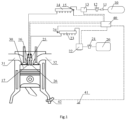
- FIG. 1 is a schematic structural diagram of a pressure coupled control system for diffusion combustion of a natural gas engine according to an embodiment of the present disclosure.
- the present disclosure provides a pressure coupled control system for diffusion combustion of a natural gas engine.
- the system includes a cylinder 30, an intake pipe 31 and an exhaust pipe 32 disposed on both sides of the cylinder 30, and a diesel fuel system and a natural gas system in communication with the top of the cylinder 30.
- the diesel fuel system includes an fuel tank 20, an fuel filter 21, a high-pressure fuel pump 22, a diesel fuel pressure adjustment unit (not shown) integrated in the high-pressure fuel pump 22 and connected to an electronic control unit 40, an fuel rail 23, an fuel injection solenoid valve 25 and an fuel injection nozzle 26 disposed on the cylinder 30, which are connected in sequence.
- the natural gas system includes a natural gas bottle 10, a natural gas pump 11, a natural gas filter 12, a natural gas pressure adjustment unit 13, a gas rail 14, a natural gas pressure sensor 15, a gas injection solenoid valve 16, and a gas injection nozzle 17 disposed on the cylinder 30, which are connected in sequence. Further, the system further includes a detection unit, which is connected to the electric control unit 40 of the natural gas engine and which is configured to detect an operating condition of the natural gas engine and send the operating condition to the electronic control unit 40.
- the detection unit includes: an accelerator pedal displacement sensor disposed at an accelerator pedal 41, wherein the accelerator pedal displacement sensor is configured to detect an accelerator signal of the accelerator pedal 41; and a phase sensor 42, which is disposed on the natural gas engine and which is configured to detect a speed signal of the natural gas engine.
- a first computing unit is integrated in the electronic control unit 40, and is configured to calculate a target diesel fuel pressure value of diesel fuel flowing into the fuel rail 23 of the natural gas engine according to the operating condition and detect an actual diesel fuel pressure value of the diesel fuel flowing into the fuel rail 23 through a diesel fuel pressure sensor 24 in the fuel rail 23.
- a second computing unit is also integrated in the electronic control unit 40, and is configured to calculate a target natural gas pressure value of natural gas flowing into the gas rail 14 of the natural gas engine according to the actual diesel fuel pressure value and adjust the natural gas flowing into the gas rail 14 through a signal of a gas rail pressure sensor in the gas rail 14.
- the system further includes an injection unit, which is configured to inject high-pressure diesel fuel and high-pressure natural gas into the cylinder 30 sequentially after the target diesel fuel pressure value and the target natural gas pressure value are established.
- the diesel fuel and natural gas injected into the natural gas engine are pressure-coupled so that the diesel fuel and natural gas injected into the natural gas engine are fully combusted, thereby increasing the diffusion combustion efficiency of the natural gas engine.
- the electronic control unit 40 of the present disclosure calculates the target diesel fuel pressure value of the diesel fuel flowing into the fuel rail 23 of the natural gas engine according to the operating condition of the engine, and detects the actual diesel fuel pressure value of the diesel fuel flowing into the fuel rail 23 through the diesel fuel pressure sensor 24 in the fuel rail 23; then, the electronic control unit 40 calculates the target natural gas pressure value of the natural gas flowing into the gas rail 14 of the natural gas engine according to the actual diesel fuel pressure value; finally, high-pressure diesel fuel and high-pressure natural gas are injected into the cylinder 30 sequentially by taking the target diesel fuel pressure value and the target natural gas pressure value as targets so as to realize a pressure-coupled control of the pressures of the natural gas and diesel fuel injected into the cylinder 30 so that the high-pressure natural gas injected into the cylinder 30 can be fully diffused and combusted in the fire core formed by the high-pressure diesel fuel, thereby reducing the possible phenomena of knocking and burst pressure of the natural gas engine; at the same time, the compression ratio, power per
- the diesel fuel pressure adjustment unit of the present disclosure is integrated in the high-pressure fuel pump 22 and connected with the electronic control unit 40, and controls an fuel-pumping volume of the high-pressure fuel pump 22 according to the target diesel fuel pressure value so that high-pressure diesel is formed in the fuel rail 23.
- the diesel fuel pressure sensor 24 of the present disclosure is disposed in the fuel rail 23 and connected to the diesel fuel pressure adjustment unit, and the diesel fuel pressure adjustment unit adjusts the fuel-pumping volume of the high-pressure fuel pump 22 according to the diesel fuel pressure signal of the diesel fuel pressure sensor 24 in the fuel rail 23, so that the pressure value of the high-pressure diesel fuel in the fuel rail 23 reaches the target diesel fuel pressure value.
- the diesel fuel pressure adjustment unit is integrated in the high-pressure fuel pump 22 and is connected to the diesel fuel pressure sensor 24 and the electronic control unit 40 respectively for transmitting the diesel fuel pressure signal of the diesel fuel pressure sensor 24 to the electronic control unit 40.
- the diesel fuel pressure adjustment unit is also capable of adjusting the fuel-pumping volume of the high-pressure fuel pump 22 according to a control signal of the electronic control unit 40 so that the pressure value of the high-pressure diesel fuel in the fuel rail 23 reaches the target diesel fuel pressure value. It should be noted that since the diesel fuel pressure adjustment unit of the present disclosure uses an electronically controlled diesel fuel pressure adjustment unit, it has the advantages of high accuracy, fast response, and high reliability.
- the natural gas pressure adjustment unit 13 of the present disclosure is connected to the electronic control unit 40 and the natural gas pump 11 respectively, and controls a gas-pumping volume of the natural gas pump 11 according to the actual diesel fuel pressure value to form high-pressure natural gas in the gas rail 14.
- the natural gas pressure sensor 15 of the present disclosure is disposed in the gas rail 14 and connected to the natural gas pressure adjustment unit 13, and the natural gas pressure adjustment unit 13 adjusts the gas-pumping volume of the natural gas pump 11 according to a natural gas pressure signal of the natural gas pressure sensor 15 in the gas rail 14 so that the pressure value of the high-pressure natural gas in the gas rail 14 reaches the target natural gas pressure value.
- the natural gas pressure adjustment unit 13 is disposed between the natural gas pump 11 and the gas rail 14 and is connected to the natural gas pressure sensor 15 and the electronic control unit 40 respectively for transmitting the natural gas pressure signal of the natural gas pressure sensor 15 to the electronic control unit 40.
- the natural gas pressure adjustment unit 13 is also capable of adjusting the gas-pumping volume of the natural gas pump 11 according to a control signal of the electronic control unit 40 so that the pressure value of the high-pressure natural gas in the gas rail 14 reaches the target natural gas pressure value. It should be noted that since the natural gas pressure adjustment unit 13 of the present disclosure uses an electronically controlled natural gas pressure adjustment unit, it has the advantages of high accuracy, fast response, and high reliability.
- the electronic control unit 40 of the present disclosure controls the fuel injection nozzle 26 through the fuel injection solenoid valve 25 to inject the high-pressure diesel fuel into the cylinder 30 with a first injection pulse width at a first injection timing, and then the gas injection solenoid valve 16 controls the gas injection nozzle 17 through the gas injection solenoid valve 16 to inject the high-pressure natural gas into the cylinder 30 with a second injection pulse width at a second injection timing.
- the electronic control unit 40 accurately controls the first injection timing and the first injection pulse width of the high-pressure diesel fuel through the fuel injection solenoid valve 25 located at the fuel injection nozzle 26 of the cylinder 30 so that the high-pressure diesel fuel is compression-combusted in the cylinder 30.
- the electronic control unit 40 accurately controls the second injection timing and the second injection pulse width of the high-pressure natural gas through the gas injection solenoid valve 16 located at the gas injection nozzle 17 so that the high-pressure natural gas is diffusion-combusted in the fire core formed by the high-pressure diesel fuel, thereby reducing the phenomena of knocking and burst pressure existing in ordinary premixed combustion and spark plug ignition engines; at the same time, the compression ratio, power per liter and thermal efficiency of the natural gas engine are effectively improved.
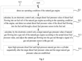
- FIG. 2 is a schematic flowchart of a pressure coupled control method for diffusion combustion of a natural gas engine according to an embodiment of the present disclosure.
- the present disclosure also provides a pressure coupled control method for diffusion combustion of a natural gas engine.
- the pressure coupled control method for diffusion combustion of the natural gas engine includes the following steps: S11: detecting an operating condition of the natural gas engine, such as determining the operating condition of the natural gas engine according to an accelerator signal and a speed signal of the natural gas engine; S12: calculating, by the electronic control unit 40, a target diesel fuel pressure value of diesel fuel flowing into the fuel rail 23 of the natural gas engine according to the operating condition, and detecting an actual diesel fuel pressure value of the diesel fuel flowing into the fuel rail 23 by the diesel fuel pressure sensor 24 in the fuel rail 23; S13: calculating, by the electronic control unit 40, a target natural gas pressure value of natural gas flowing into the gas rail 14 of the natural gas engine according to the actual diesel fuel pressure value, and adjusting the natural gas flowing into the gas rail 14 through a signal of the gas rail pressure sensor in the gas rail 14; S14: after the target diesel fuel pressure value and the target natural gas pressure value are
- the diesel fuel and natural gas injected into the natural gas engine are pressure-coupled so that the diesel fuel and natural gas injected into the natural gas engine are fully combusted, thereby increasing the diffusion combustion efficiency of the natural gas engine.
- the electronic control unit 40 of the present disclosure calculates the target diesel fuel pressure value of the diesel fuel flowing into the fuel rail 23 of the natural gas engine according to the operating condition of the engine, and detects the actual diesel fuel pressure value of the diesel fuel flowing into the fuel rail 23 through the diesel fuel pressure sensor 24 in the fuel rail 23; then, the electronic control unit 40 calculates the target natural gas pressure value of the natural gas flowing into the gas rail 14 of the natural gas engine according to the actual diesel fuel pressure value; finally, high-pressure diesel fuel and high-pressure natural gas are injected into the cylinder 30 sequentially by taking the target diesel fuel pressure value and the target natural gas pressure value as targets so as to realize a pressure-coupled control of the pressures of natural gas and diesel fuel injected into the cylinder 30 so that the high-pressure natural gas injected into the cylinder
- the pressure coupled control method for diffusion combustion of the natural gas engine of the present disclosure a control method for only one operating condition is elaborated.
- the operating condition of the natural gas engine will be detected in real time, and the target diesel fuel pressure value and the target natural gas pressure value will be adjusted in time according to a change in the operating condition of the natural gas engine.
- the natural gas engine is provided with the high-pressure fuel pump 22 and the fuel rail 23 that are located between the fuel tank 20 and the cylinder 30, wherein the fuel rail 23 is used to store high-pressure diesel fuel, the diesel fuel pressure sensor 24 is disposed in the fuel rail 23, and step S12 includes: S121: forming high-pressure diesel in the fuel rail 23 by controlling an fuel-pumping volume of the high-pressure fuel pump 22 according to the target diesel fuel pressure value; and S122: detecting the actual diesel fuel pressure value of the high-pressure diesel fuel flowing into the fuel rail 23 by the diesel fuel pressure sensor 24, and adjusting the fuel-pumping volume of the high-pressure fuel pump 22 according to the actual diesel fuel pressure value, so that the pressure value of the high-pressure diesel fuel in the fuel rail 23 reaches the target diesel fuel pressure value.
- the present disclosure by storing the high-pressure diesel fuel in the fuel rail 23 and adjusting the pressure value of the high-pressure diesel fuel in the fuel rail 23 to the target diesel fuel pressure value through the diesel fuel pressure sensor 24 in the fuel rail 23, the accuracy of the fuel pressure value of the high-pressure diesel fuel before being injected into cylinder 30 is improved, and the influence of the fuel pressure loss of the high-pressure diesel fuel in the fuel pipe of the fuel tank 20 on the fuel pressure value of the high-pressure diesel fuel is reduced.
- the natural gas engine is provided with the natural gas pump 11 and the gas rail 14 that are located between the natural gas bottle 10 and the cylinder 30, wherein the gas rail 14 is used to store high-pressure natural gas, the natural gas pressure sensor 15 is disposed in the gas rail 14, and step S 13 includes: S 131: forming high-pressure natural gas in the gas rail 14 by controlling a gas-pumping volume of the natural gas pump 11 according to the actual diesel fuel pressure value; and S132: adjusting the gas-pumping volume of the natural gas pump 11 according to a natural gas pressure signal of the natural gas pressure sensor 15 in the gas rail 14 so that the pressure value of the high-pressure natural gas in the gas rail 14 reaches the target natural gas pressure value.
- the present disclosure by storing the high-pressure natural gas in the gas rail 14 and adjusting the pressure value of the high-pressure natural gas in the gas rail 14 to the target natural gas pressure value through the natural gas pressure sensor 15 in the fuel rail 14, the accuracy of the gas pressure of the high-pressure natural gas before being injected into the cylinder 30 is improved, and the influence of the gas pressure loss of the high-pressure natural gas in the gas pipe of the natural gas bottle 10 on the gas pressure value of the natural gas is reduced.
- step S 14 includes: S 141: controlling the fuel injection nozzle 26 to inject the high-pressure diesel fuel into the cylinder 30 with a first injection pulse width at a first injection timing; and S 142: controlling the gas injection nozzle 17 to inject the high-pressure natural gas into the cylinder 30 with a second injection pulse width at a second injection timing.
- the electronic control unit 40 accurately controls the first injection timing and the first injection pulse width of the high-pressure diesel fuel through the fuel injection solenoid valve 25 located at the fuel injection nozzle 26 of the cylinder 30 so that the high-pressure diesel fuel is compression-combusted in the cylinder 30.
- the electronic control unit 40 accurately controls the second injection timing and the second injection pulse width of the high-pressure natural gas through the gas injection solenoid valve 16 located at the gas injection nozzle 17 of the cylinder 30 so that the high-pressure natural gas is diffusion-combusted in the fire core formed by the high-pressure diesel fuel, thereby reducing the phenomena of knocking and burst pressure existing in ordinary premixed combustion and spark plug ignition engines; at the same time, the compression ratio, power per liter and thermal efficiency of the natural gas engine are effectively improved.
Landscapes
- Engineering & Computer Science (AREA)
- Chemical & Material Sciences (AREA)
- Combustion & Propulsion (AREA)
- Mechanical Engineering (AREA)
- General Engineering & Computer Science (AREA)
- Oil, Petroleum & Natural Gas (AREA)
- Electrical Control Of Air Or Fuel Supplied To Internal-Combustion Engine (AREA)
- Output Control And Ontrol Of Special Type Engine (AREA)
- Combined Controls Of Internal Combustion Engines (AREA)
Claims (7)
- System zur druckgekoppelten Steuerung zur Diffusionsverbrennung eines Erdgasmotors, umfassend:einen Zylinder, (30), ein Ansaugrohr (31) und ein Abgasrohr (32), die an beiden Seiten des Zylinders (30) angeordnet sind;ein Dieselkraftstoffsystem und ein Erdgassystem in Verbindung mit einer Oberseite des Zylinders (30), wobeidas Dieselkraftstoffsystem einen Kraftstofftank (20), einen Kraftstofffilter (21) eine Kraftstoff-Hochdruckpumpe (22), eine Dieselkraftstoff-Druckanpassungseinheit, eine Kraftstoffleitung (23), einen Dieselkraftstoff-Drucksensor (24), ein Kraftstoffeinspritz-Magnetventil (25) und eine Kraftstoffeinspritzdüse (26) umfasst, wobei der Kraftstofffilter (21) zwischen dem Kraftstofftank (20) und der Kraftstoff-Hochdruckpumpe (22) angeschlossen ist, die Kraftstoffleitung (23) zwischen der Kraftstoff-Hochdruckpumpe (22) und dem Kraftstoffeinspritz-Magnetventil (25) angeschlossen ist, das Kraftstoffeinspritz-Magnetventil (25) zwischen der Kraftstoffleitung (23) und der Kraftstoffeinspritzdüse (26) angeschlossen ist, die Dieselkraftstoff-Druckanpassungseinheit in der Kraftstoff-Hochdruckpumpe (22) integriert ist und an eine elektronische Steuereinheit (40) des Erdgasmotors angeschlossen ist, der Dieselkraftstoff-Drucksensor (24) in der Kraftstoffleitung (23) angeordnet ist, und die Kraftstoffeinspritzdüse (26) am Zylinder (30) angeordnet ist,wobei das Erdgassystem eine Erdgasflasche (10), eine Erdgaspumpe (11), einen Erdgasfilter (12), eine Erdgas-Druckanpassungseinheit (13), eine Gasleitung (14), einen Erdgas-Drucksensor (15), ein Gaseinspritz-Magnetventil (16) und eine Gaseinspritzdüse (17) umfasst, wobei die Erdgaspumpe (11) zwischen der Erdgasflasche (10) und dem Erdgasfilter (12) angeschlossen ist, die Erdgas-Druckanpassungseinheit (13) zwischen dem Erdgasfilter (12) und der Gasleitung (14) angeschlossen ist, das Gaseinspritz-Magnetventil (16) zwischen der Gasleitung (14) und der Gaseinspritzdüse (17) angeschlossen ist, der Erdgas-Drucksensor (15) in der Gasleitung (14) angeordnet ist, und die Gaseinspritzdüse (17) am Zylinder (30) angeordnet ist,wobei das System zur druckgekoppelten Steuerung weiter umfasst:eine Detektionseinheit, die an die elektronische Steuereinheit (40) angeschlossen ist, und die konfiguriert ist, einen Betriebszustand des Erdgasmotors zu detektieren, und den Betriebszustand an die elektronische Steuereinheit (40) zu senden, wobei die Detektionseinheit einen Beschleunigungspedal-Bewegungssensor umfasst, der an einem Beschleunigungspedal (41) des Erdgasmotors angeordnet ist, und konfiguriert ist, um ein Beschleunigungssignal des Beschleunigungspedals (41) zu detektieren, und einen Phasensensor (42), der am Erdgasmotor angeordnet ist und konfiguriert ist, um ein Geschwindigkeitssignal des Erdgasmotors zu detektieren,eine erste Berechnungseinheit, die in der elektronischen Steuereinheit (40) integriert ist, und die konfiguriert ist, um einen Dieselkraftstoffdruck-Zielwert des Dieselkraftstoffs zu berechnen, der entsprechend dem Betriebszustand in die Kraftstoffleitung (23) des Erdgasmotors fließt, undeine zweite Berechnungseinheit, die in der elektronischen Steuereinheit (40) integriert ist,wobeider Dieselkraftstoff-Drucksensor (24) an die elektronische Steuereinheit (40) angeschlossen ist und konfiguriert ist, um einen tatsächlichen Dieselkraftstoffdruckwert von Dieselkraftstoff zu detektieren, der in die Kraftstoffleitung (23) fließt,die Dieselkraftstoff-Druckanpassungseinheit konfiguriert ist, um Dieselkraftstoffdruck in der Kraftstoffleitung (23) anzupassen, sodass der Druckwert des Dieselkraftstoffs in der Kraftstoffleitung (23) den Dieselkraftstoffdruck-Zielwert erreicht;die zweite Berechnungseinheit konfiguriert ist, um einen Erdgasdruck-Zielwert von Erdgas zu berechnen, das entsprechend dem tatsächlichen Dieselkraftstoffdruckwert in die Gasleitung (14) des Erdgasmotors fließt,die Erdgas-Druckanpassungseinheit (13) an die elektronische Steuereinheit (40) angeschlossen ist und konfiguriert ist, um Erdgas, das in die Gasleitung (14) fließt, basierend auf einem Signal des Erdgas-Drucksensors (15) anzupassen, sodass ein Druckwert des Erdgases in der Gasleitung (14) den Erdgasdruck-Zielwert erreicht; unddie elektronische Steuereinheit (40) konfiguriert ist, um, nachdem ein Druckwert von Dieselkraftstoff in der Kraftstoffleitung (23) den Dieselkraftstoffdruck-Zielwert erreicht hat, und ein Druckwert des Erdgases in der Gasleitung (14) den Erdgasdruck-Zielwert erreicht hat, die Kraftstoffeinspritzdüse (26) durch das Kraftstoffeinspritz-Magnetventil (25) zu steuern, um Hochdruck-Dieselkraftstoff mit einer ersten Einspritzimpulsbreite zu einem ersten Einspritzzeitpunkt in den Zylinder (30) einzuspritzen, sodass der Hochdruck-Dieselkraftstoff in dem Zylinder (30) verbrannt wird, und die Gaseinspritzdüse (17) durch das Gaseinspritz-Magnetventil (16) zu steuern, um Hochdruck-Erdgas mit einer zweiten Einspritzimpulsbreite zu einem zweiten Einspritzzeitpunkt in den Zylinder (30) einzuspritzen, sodass das Hochdruck-Erdgas in einem Feuerkern diffusionsverbrannt wird, der durch den Hochdruck-Dieselkraftstoff gebildet wird.
- System zur druckgekoppelten Steuerung zur Diffusionsverbrennung des Erdgasmotors nach Anspruch 1, wobei die Kraftstoffleitung (23) verwendet wird, um Hochdruck-Dieselkraftstoff zu speichern; unddie Dieselkraftstoff-Druckanpassungseinheit ein Kraftstoffpumpvolumen der Kraftstoff-Hochdruckpumpe (22) entsprechend dem Dieselkraftstoffdruck-Zielwert steuert, sodass Hochdruck-Diesel in der Kraftstoffleitung (23) gebildet wird, undder DieselkraftstoffDrucksensor (24) an die Dieselkraftstoff-Druckanpassungseinheit angeschlossen ist, wobei die Dieselkraftstoff-Druckanpassungseinheit das Kraftstoffpumpvolumen der Kraftstoff-Hochdruckpumpe (22) entsprechend dem tatsächlichen Dieselkraftstoffdruckwert aus dem Dieselkraftstoff-Drucksensor (24) anpasst, sodass ein Druckwert des Hochdruck-Dieselkraftstoffs in der Kraftstoffleitung (23) den Dieselkraftstoffdruck-Zielwert erreicht.
- System zur druckgekoppelten Steuerung zur Diffusionsverbrennung des Erdgasmotors nach Anspruch 2, wobei die Gasleitung (14) verwendet wird, um Hochdruck-Erdgas zu speichern;die Erdgas-Druckanpassungseinheit (13) an die Erdgaspumpe (11) angeschlossen ist, und ein Gaspumpvolumen der Erdgaspumpe (11) entsprechend dem tatsächlichen Dieselkraftstoff-Druckwert steuert, um Hochdruck-Erdgas in der Gasleitung (14) zu bilden; undder Erdgas-Drucksensor (15) an die Erdgas-Druckanpassungseinheit (13) angeschlossen ist, wobei die Erdgas-Druckanpassungseinheit das Gaspumpvolumen der Erdgaspumpe (11) entsprechend einem Erdgas-Drucksignal des Erdgas-Drucksensors (15) steuert, sodass der Druckwert des Hochdruck-Erdgases in der Gasleitung (14) den Erdgasdruck-Zielwert erreicht.
- Verfahren zur druckgekoppelten Steuerung des Systems zur druckgekoppelten Steuerung zur Diffusionsverbrennung des Erdgasmotors nach Anspruch 1, die folgenden Schritte umfassend:S11: Detektieren über die Detektionseinheit des Betriebszustands des Erdgasmotors,S12: Berechnen durch die elektronische Steuereinheit (40) des Dieselkraftstoffdruck-Zielwerts von Dieselkraftstoff, der entsprechend dem Betriebszustand des Erdgasmotors in die Kraftstoffleitung (14) des Erdgasmotors fließt, Detektieren eines tatsächlichen Dieselkraftstoffdruckwerts von Dieselkraftstoff, der in die Kraftstoffleitung (23) fließt, durch den Dieselkraftstoff-Drucksensor (24), und Anpassen des Dieselkraftstoffdrucks in der Kraftstoffleitung (23) durch die Dieselkraftstoff-Druckanpassungseinheit, sodass der Druckwert des Dieselkraftstoffs in der Kraftstoffleitung (23) den Dieselkraftstoffdruck-Zielwert erreicht;S13: Berechnen durch die elektronische Steuereinheit (40) des Erdgasdruck-Zielwerts von Erdgas, das entsprechend dem tatsächlichen Dieselkraftstoffdruckwert in die Gasleitung (14) des Erdgasmotors fließt, und Anpassen des Erdgases, das in die Gasleitung (14) fließt, über die Erdgas-Druckanpassungseinheit, basierend auf einem Signal des Erdgas-Drucksensors (15), sodass ein Druckwert des Erdgases in der Gasleitung (14) den Erdgasdruck-Zielwert erreicht; undS14: nachdem der Druckwert von Dieselkraftstoff in der Kraftstoffleitung (23) den Dieselkraftstoffdruck-Zielwert erreicht hat, und der Druckwert des Erdgases in der Gasleitung (14) den Erdgasdruck-Zielwert erreicht hat, Steuern der Kraftstoffeinspritzdüse (26) über das Kraftstoffeinspritz-Magnetventil (25), um Hochdruck-Dieselkraftstoff mit einer ersten Einspritzimpulsbreite zu einem ersten Einspritzzeitpunkt in den Zylinder (30) einzuspritzen, sodass der Hochdruck-Dieselkraftstoff in dem Zylinder (30) verbrannt wird, und Steuern der Gaseinspritzdüse (17) über das Gaseinspritz-Magnetventil (16), um Hochdruck-Erdgas mit einer zweiten Einspritzimpulsbreite zu einem zweiten Einspritzzeitpunkt in den Zylinder (30) einzuspritzen, sodass das Hochdruck-Erdgas in einem Feuerkern diffusionsverbrannt wird, der durch den Hochdruck-Dieselkraftstoff gebildet wird.
- Verfahren zur druckgekoppelten Steuerung nach Anspruch 4, wobei Schritt S11 umfasst:
Detektieren eines Beschleunigungssignals des Beschleunigungspedals (41) durch den Beschleunigungspedal-Bewegungssensor und eines Geschwindigkeitssignals des Erdgasmotors durch den Phasensensor (42). - Verfahren zur druckgekoppelten Steuerung nach Anspruch 5, wobei Schritt S12 umfasst:S121: Bilden von Hochdruck-Diesel in der Kraftstoffleitung (23) durch Steuern eines Kraftstoffpumpvolumens der Kraftstoff-Hochdruckpumpe (22) über die Dieselkraftstoff-Druckanpassungseinheit entsprechend dem Dieselkraftstoffdruck-Zielwert; undS122: Anpassen des Kraftstoffpumpvolumens der Kraftstoff-Hochdruckpumpe (22) über die Dieselkraftstoff-Druckanpassungseinheit entsprechend dem tatsächlichen Dieselkraftstoffdruckwert, sodass der Druckwert des Hochdruck-Dieselkraftstoffs in der Kraftstoffleitung (23) den Dieselkraftstoffdruck-Zielwert erreicht.
- Verfahren zur druckgekoppelten Steuerung nach Anspruch 6, wobei Schritt S13 umfasst:S131: Bilden von Hochdruck-Erdgas in der Gasleitung (14) durch Steuern eines Gaspumpvolumens der Erdgaspumpe (11) über die Erdgas-Druckanpassungseinheit entsprechend dem tatsächlichen Dieselkraftstoff-Druckwert; undS132: Anpassen des Gaspumpvolumens der Erdgaspumpe (11) über die die Erdgas-Druckanpassungseinheit entsprechend einem Erdgas-Drucksignal des Erdgas-Drucksensors (15) in der Gasleitung (14), sodass der Druckwert des Hochdruck-Erdgases in der Gasleitung (14) den Erdgasdruck-Zielwert erreicht.
Priority Applications (1)
| Application Number | Priority Date | Filing Date | Title |
|---|---|---|---|
| RS20230614A RS64396B1 (sr) | 2018-06-21 | 2018-06-29 | Postupak i sistem kontrole po principu pritiska za difuziono sagorevanje kod motora na prirodni gas |
Applications Claiming Priority (2)
| Application Number | Priority Date | Filing Date | Title |
|---|---|---|---|
| CN201810645725.4A CN109057977B (zh) | 2018-06-21 | 2018-06-21 | 天然气发动机扩散燃烧的压力耦合控制方法和系统 |
| PCT/CN2018/093796 WO2019242040A1 (zh) | 2018-06-21 | 2018-06-29 | 天然气发动机扩散燃烧的压力耦合控制方法和系统 |
Publications (3)
| Publication Number | Publication Date |
|---|---|
| EP3741978A1 EP3741978A1 (de) | 2020-11-25 |
| EP3741978A4 EP3741978A4 (de) | 2021-03-24 |
| EP3741978B1 true EP3741978B1 (de) | 2023-05-31 |
Family
ID=64821378
Family Applications (1)
| Application Number | Title | Priority Date | Filing Date |
|---|---|---|---|
| EP18923129.3A Active EP3741978B1 (de) | 2018-06-21 | 2018-06-29 | Verfahren und system zur druckgekoppelten steuerung einer brennkraftmaschine |
Country Status (5)
| Country | Link |
|---|---|
| US (1) | US10941715B2 (de) |
| EP (1) | EP3741978B1 (de) |
| CN (1) | CN109057977B (de) |
| RS (1) | RS64396B1 (de) |
| WO (1) | WO2019242040A1 (de) |
Families Citing this family (8)
| Publication number | Priority date | Publication date | Assignee | Title |
|---|---|---|---|---|
| IT201800009743A1 (it) * | 2018-10-24 | 2020-04-24 | Landi Renzo Spa | Dispositivo di regolazione della pressione di un combustibile gassoso e sistema di alimentazione a doppio combustibile con iniezione diretta |
| CN111188690B (zh) * | 2020-01-14 | 2022-08-05 | 潍柴动力股份有限公司 | 一种天然气发动机的燃烧控制方法及控制系统 |
| CN111765020B (zh) * | 2020-07-08 | 2021-11-19 | 潍柴动力股份有限公司 | 一种燃气轨压调节方法及系统 |
| CN111810304A (zh) * | 2020-08-05 | 2020-10-23 | 英嘉动力科技无锡有限公司 | 一种双燃料直喷系统发动机的燃料压力控制方法 |
| CH719186A2 (de) * | 2021-12-01 | 2023-06-15 | Liebherr Machines Bulle Sa | Verfahren zum Betrieb einer Verbrennungskraftmaschine mit einem gasförmigen Kraftstoff sowie Verbrennungskraftmaschine. |
| CN114992020B (zh) * | 2022-05-10 | 2024-03-19 | 潍柴动力股份有限公司 | Hpdi发动机燃料轨压的确定方法、确定装置和车辆的控制器 |
| CN119145960A (zh) * | 2024-09-25 | 2024-12-17 | 潍柴动力股份有限公司 | 双燃料发动机燃气压力的控制方法、电子设备及存储介质 |
| CN119532043A (zh) * | 2024-12-03 | 2025-02-28 | 潍柴动力股份有限公司 | 双燃料喷射系统、控制方法、控制装置及车辆 |
Family Cites Families (10)
| Publication number | Priority date | Publication date | Assignee | Title |
|---|---|---|---|---|
| JP4483752B2 (ja) * | 2005-09-20 | 2010-06-16 | マツダ株式会社 | デュアルフューエルエンジンの制御装置 |
| CN202001119U (zh) * | 2011-01-17 | 2011-10-05 | 吕国怀 | 一种双燃料发动机油气比例控制装置 |
| CA2773651C (en) * | 2012-04-05 | 2013-04-09 | Westport Power Inc. | Method and apparatus for controlling fuel pressure in a gaseous fuelled internal combustion engine |
| US8977473B2 (en) * | 2012-08-29 | 2015-03-10 | Caterpillar Inc. | Pressure control strategy for dual fuel compression ignition engine and machine using same |
| US20140136079A1 (en) * | 2012-11-15 | 2014-05-15 | Caterpillar Inc. | Control Strategy In Gaseous Fuel Internal Combustion Engine |
| US9518518B2 (en) * | 2013-04-19 | 2016-12-13 | Caterpillar Inc. | Dual fuel common rail transient pressure control and engine using same |
| US9482165B2 (en) * | 2013-04-19 | 2016-11-01 | Caterpillar Inc. | Dual fuel common rail depressurization during engine shutdown and machine using same |
| US9181886B2 (en) * | 2013-05-08 | 2015-11-10 | Caterpillar Inc. | Dual fuel common rail transient pressure control and engine using same |
| US9657653B2 (en) * | 2014-06-09 | 2017-05-23 | Caterpillar Inc. | Gas pressure high and low detection |
| CN104121102B (zh) * | 2014-07-23 | 2016-03-23 | 山东大学 | 微量柴油引燃直喷天然气发动机燃料供给系统及控制方法 |
-
2018
- 2018-06-21 CN CN201810645725.4A patent/CN109057977B/zh active Active
- 2018-06-29 EP EP18923129.3A patent/EP3741978B1/de active Active
- 2018-06-29 RS RS20230614A patent/RS64396B1/sr unknown
- 2018-06-29 WO PCT/CN2018/093796 patent/WO2019242040A1/zh not_active Ceased
-
2020
- 2020-08-13 US US16/992,522 patent/US10941715B2/en active Active
Also Published As
| Publication number | Publication date |
|---|---|
| US10941715B2 (en) | 2021-03-09 |
| RS64396B1 (sr) | 2023-08-31 |
| US20200370482A1 (en) | 2020-11-26 |
| WO2019242040A1 (zh) | 2019-12-26 |
| EP3741978A4 (de) | 2021-03-24 |
| CN109057977B (zh) | 2019-11-01 |
| CN109057977A (zh) | 2018-12-21 |
| EP3741978A1 (de) | 2020-11-25 |
Similar Documents
| Publication | Publication Date | Title |
|---|---|---|
| EP3741978B1 (de) | Verfahren und system zur druckgekoppelten steuerung einer brennkraftmaschine | |
| CN100406703C (zh) | 燃料喷射系统 | |
| US6467466B1 (en) | Gas leakage detection and fail-safe control method for gas-fueled internal combustion engine and apparatus for implementing the same | |
| US8042517B2 (en) | Fuel property detector for internal combustion engine | |
| EP0981685B1 (de) | Verfahren zur ermittlung eines offenen ventil fehlerzustands beim einlassventil für gasförmigen treibstoff eines verbrennungsmotors | |
| JP5727395B2 (ja) | 内燃機関の制御装置 | |
| US8423267B2 (en) | Cetane number detection device and cetane number detection method | |
| US9334812B2 (en) | Fuel supply control system for multi-fuel internal combustion engine | |
| JP2005214201A (ja) | NOxおよびUHCの排出量を最低限に抑えるためのマイクロパイロット燃料噴射制御の方法と装置 | |
| CN104121102A (zh) | 微量柴油引燃直喷天然气发动机燃料供给系统及控制方法 | |
| US9964053B2 (en) | Combustion control device for gas engine | |
| JP2009203883A (ja) | 内燃機関の故障原因推定方法および装置 | |
| EP3336337B1 (de) | Verfahren zum betreiben eines verbrennungsmotors mit gasförmigem brennstoff | |
| CN203978671U (zh) | 微量柴油引燃直喷天然气发动机燃料供给系统 | |
| JP2004346911A (ja) | Cngエンジンの燃料性状別制御方法 | |
| CN107690522B (zh) | 操作内燃活塞发动机的方法、控制系统及内燃活塞发动机 | |
| JP6002797B2 (ja) | 内燃機関の制御装置 | |
| KR20140124951A (ko) | 이중연료엔진의 가스연료 압력 제어 방법 | |
| JP2007231883A (ja) | 内燃機関の空燃比制御装置 | |
| JP5338686B2 (ja) | 内燃機関の燃料アルコール濃度判定装置 | |
| WO2023230344A1 (en) | Control system for internal combustion engine, internal combustion engine configured to control combustion, and method of control thereof | |
| JPS62228642A (ja) | 筒内直接噴射式内燃機関 | |
| CN110284999A (zh) | 一种稀薄燃烧系统及车辆 | |
| JP5195466B2 (ja) | ディーゼル機関の制御装置 | |
| KR20140127454A (ko) | 이중연료엔진의 연소지속시간 제어를 통한 실린더 밸런싱 장치 및 방법 |
Legal Events
| Date | Code | Title | Description |
|---|---|---|---|
| STAA | Information on the status of an ep patent application or granted ep patent |
Free format text: STATUS: THE INTERNATIONAL PUBLICATION HAS BEEN MADE |
|
| PUAI | Public reference made under article 153(3) epc to a published international application that has entered the european phase |
Free format text: ORIGINAL CODE: 0009012 |
|
| STAA | Information on the status of an ep patent application or granted ep patent |
Free format text: STATUS: REQUEST FOR EXAMINATION WAS MADE |
|
| 17P | Request for examination filed |
Effective date: 20200821 |
|
| AK | Designated contracting states |
Kind code of ref document: A1 Designated state(s): AL AT BE BG CH CY CZ DE DK EE ES FI FR GB GR HR HU IE IS IT LI LT LU LV MC MK MT NL NO PL PT RO RS SE SI SK SM TR |
|
| AX | Request for extension of the european patent |
Extension state: BA ME |
|
| A4 | Supplementary search report drawn up and despatched |
Effective date: 20210219 |
|
| RIC1 | Information provided on ipc code assigned before grant |
Ipc: F02D 19/10 20060101ALI20210215BHEP Ipc: F02D 19/06 20060101ALI20210215BHEP Ipc: F02D 41/00 20060101ALI20210215BHEP Ipc: F02D 19/08 20060101ALI20210215BHEP Ipc: F02D 41/38 20060101ALI20210215BHEP Ipc: F02D 41/30 20060101AFI20210215BHEP |
|
| DAV | Request for validation of the european patent (deleted) | ||
| DAX | Request for extension of the european patent (deleted) | ||
| STAA | Information on the status of an ep patent application or granted ep patent |
Free format text: STATUS: EXAMINATION IS IN PROGRESS |
|
| 17Q | First examination report despatched |
Effective date: 20211123 |
|
| REG | Reference to a national code |
Ref country code: DE Ref legal event code: R079 Ref document number: 602018050616 Country of ref document: DE Free format text: PREVIOUS MAIN CLASS: F02D0041300000 Ipc: F02D0019060000 |
|
| GRAP | Despatch of communication of intention to grant a patent |
Free format text: ORIGINAL CODE: EPIDOSNIGR1 |
|
| STAA | Information on the status of an ep patent application or granted ep patent |
Free format text: STATUS: GRANT OF PATENT IS INTENDED |
|
| RIC1 | Information provided on ipc code assigned before grant |
Ipc: F02D 41/38 20060101ALI20221206BHEP Ipc: F02D 41/00 20060101ALI20221206BHEP Ipc: F02D 41/30 20060101ALI20221206BHEP Ipc: F02D 19/10 20060101ALI20221206BHEP Ipc: F02D 19/08 20060101ALI20221206BHEP Ipc: F02D 19/06 20060101AFI20221206BHEP |
|
| INTG | Intention to grant announced |
Effective date: 20230104 |
|
| GRAS | Grant fee paid |
Free format text: ORIGINAL CODE: EPIDOSNIGR3 |
|
| GRAA | (expected) grant |
Free format text: ORIGINAL CODE: 0009210 |
|
| STAA | Information on the status of an ep patent application or granted ep patent |
Free format text: STATUS: THE PATENT HAS BEEN GRANTED |
|
| AK | Designated contracting states |
Kind code of ref document: B1 Designated state(s): AL AT BE BG CH CY CZ DE DK EE ES FI FR GB GR HR HU IE IS IT LI LT LU LV MC MK MT NL NO PL PT RO RS SE SI SK SM TR |
|
| REG | Reference to a national code |
Ref country code: GB Ref legal event code: FG4D Ref country code: CH Ref legal event code: EP |
|
| REG | Reference to a national code |
Ref country code: DE Ref legal event code: R096 Ref document number: 602018050616 Country of ref document: DE |
|
| REG | Reference to a national code |
Ref country code: AT Ref legal event code: REF Ref document number: 1571052 Country of ref document: AT Kind code of ref document: T Effective date: 20230615 |
|
| REG | Reference to a national code |
Ref country code: IE Ref legal event code: FG4D |
|
| PGFP | Annual fee paid to national office [announced via postgrant information from national office to epo] |
Ref country code: FR Payment date: 20230629 Year of fee payment: 6 |
|
| REG | Reference to a national code |
Ref country code: SE Ref legal event code: TRGR |
|
| REG | Reference to a national code |
Ref country code: LT Ref legal event code: MG9D |
|
| REG | Reference to a national code |
Ref country code: NL Ref legal event code: MP Effective date: 20230531 |
|
| REG | Reference to a national code |
Ref country code: AT Ref legal event code: MK05 Ref document number: 1571052 Country of ref document: AT Kind code of ref document: T Effective date: 20230531 |
|
| PG25 | Lapsed in a contracting state [announced via postgrant information from national office to epo] |
Ref country code: NO Free format text: LAPSE BECAUSE OF FAILURE TO SUBMIT A TRANSLATION OF THE DESCRIPTION OR TO PAY THE FEE WITHIN THE PRESCRIBED TIME-LIMIT Effective date: 20230831 Ref country code: ES Free format text: LAPSE BECAUSE OF FAILURE TO SUBMIT A TRANSLATION OF THE DESCRIPTION OR TO PAY THE FEE WITHIN THE PRESCRIBED TIME-LIMIT Effective date: 20230531 Ref country code: AT Free format text: LAPSE BECAUSE OF FAILURE TO SUBMIT A TRANSLATION OF THE DESCRIPTION OR TO PAY THE FEE WITHIN THE PRESCRIBED TIME-LIMIT Effective date: 20230531 |
|
| PGFP | Annual fee paid to national office [announced via postgrant information from national office to epo] |
Ref country code: MC Payment date: 20230726 Year of fee payment: 6 |
|
| PG25 | Lapsed in a contracting state [announced via postgrant information from national office to epo] |
Ref country code: PL Free format text: LAPSE BECAUSE OF FAILURE TO SUBMIT A TRANSLATION OF THE DESCRIPTION OR TO PAY THE FEE WITHIN THE PRESCRIBED TIME-LIMIT Effective date: 20230531 Ref country code: NL Free format text: LAPSE BECAUSE OF FAILURE TO SUBMIT A TRANSLATION OF THE DESCRIPTION OR TO PAY THE FEE WITHIN THE PRESCRIBED TIME-LIMIT Effective date: 20230531 Ref country code: LV Free format text: LAPSE BECAUSE OF FAILURE TO SUBMIT A TRANSLATION OF THE DESCRIPTION OR TO PAY THE FEE WITHIN THE PRESCRIBED TIME-LIMIT Effective date: 20230531 Ref country code: LT Free format text: LAPSE BECAUSE OF FAILURE TO SUBMIT A TRANSLATION OF THE DESCRIPTION OR TO PAY THE FEE WITHIN THE PRESCRIBED TIME-LIMIT Effective date: 20230531 Ref country code: IS Free format text: LAPSE BECAUSE OF FAILURE TO SUBMIT A TRANSLATION OF THE DESCRIPTION OR TO PAY THE FEE WITHIN THE PRESCRIBED TIME-LIMIT Effective date: 20230930 Ref country code: HR Free format text: LAPSE BECAUSE OF FAILURE TO SUBMIT A TRANSLATION OF THE DESCRIPTION OR TO PAY THE FEE WITHIN THE PRESCRIBED TIME-LIMIT Effective date: 20230531 Ref country code: GR Free format text: LAPSE BECAUSE OF FAILURE TO SUBMIT A TRANSLATION OF THE DESCRIPTION OR TO PAY THE FEE WITHIN THE PRESCRIBED TIME-LIMIT Effective date: 20230901 |
|
| PGFP | Annual fee paid to national office [announced via postgrant information from national office to epo] |
Ref country code: RS Payment date: 20230727 Year of fee payment: 6 Ref country code: DE Payment date: 20230808 Year of fee payment: 6 |
|
| PG25 | Lapsed in a contracting state [announced via postgrant information from national office to epo] |
Ref country code: FI Free format text: LAPSE BECAUSE OF FAILURE TO SUBMIT A TRANSLATION OF THE DESCRIPTION OR TO PAY THE FEE WITHIN THE PRESCRIBED TIME-LIMIT Effective date: 20230531 |
|
| PG25 | Lapsed in a contracting state [announced via postgrant information from national office to epo] |
Ref country code: SK Free format text: LAPSE BECAUSE OF FAILURE TO SUBMIT A TRANSLATION OF THE DESCRIPTION OR TO PAY THE FEE WITHIN THE PRESCRIBED TIME-LIMIT Effective date: 20230531 |
|
| PG25 | Lapsed in a contracting state [announced via postgrant information from national office to epo] |
Ref country code: SM Free format text: LAPSE BECAUSE OF FAILURE TO SUBMIT A TRANSLATION OF THE DESCRIPTION OR TO PAY THE FEE WITHIN THE PRESCRIBED TIME-LIMIT Effective date: 20230531 Ref country code: SK Free format text: LAPSE BECAUSE OF FAILURE TO SUBMIT A TRANSLATION OF THE DESCRIPTION OR TO PAY THE FEE WITHIN THE PRESCRIBED TIME-LIMIT Effective date: 20230531 Ref country code: RO Free format text: LAPSE BECAUSE OF FAILURE TO SUBMIT A TRANSLATION OF THE DESCRIPTION OR TO PAY THE FEE WITHIN THE PRESCRIBED TIME-LIMIT Effective date: 20230531 Ref country code: PT Free format text: LAPSE BECAUSE OF FAILURE TO SUBMIT A TRANSLATION OF THE DESCRIPTION OR TO PAY THE FEE WITHIN THE PRESCRIBED TIME-LIMIT Effective date: 20231002 Ref country code: EE Free format text: LAPSE BECAUSE OF FAILURE TO SUBMIT A TRANSLATION OF THE DESCRIPTION OR TO PAY THE FEE WITHIN THE PRESCRIBED TIME-LIMIT Effective date: 20230531 Ref country code: DK Free format text: LAPSE BECAUSE OF FAILURE TO SUBMIT A TRANSLATION OF THE DESCRIPTION OR TO PAY THE FEE WITHIN THE PRESCRIBED TIME-LIMIT Effective date: 20230531 Ref country code: CZ Free format text: LAPSE BECAUSE OF FAILURE TO SUBMIT A TRANSLATION OF THE DESCRIPTION OR TO PAY THE FEE WITHIN THE PRESCRIBED TIME-LIMIT Effective date: 20230531 |
|
| REG | Reference to a national code |
Ref country code: CH Ref legal event code: PL |
|
| REG | Reference to a national code |
Ref country code: BE Ref legal event code: MM Effective date: 20230630 |
|
| PG25 | Lapsed in a contracting state [announced via postgrant information from national office to epo] |
Ref country code: LU Free format text: LAPSE BECAUSE OF NON-PAYMENT OF DUE FEES Effective date: 20230629 |
|
| REG | Reference to a national code |
Ref country code: DE Ref legal event code: R097 Ref document number: 602018050616 Country of ref document: DE |
|
| REG | Reference to a national code |
Ref country code: IE Ref legal event code: MM4A |
|
| PG25 | Lapsed in a contracting state [announced via postgrant information from national office to epo] |
Ref country code: LU Free format text: LAPSE BECAUSE OF NON-PAYMENT OF DUE FEES Effective date: 20230629 |
|
| PGFP | Annual fee paid to national office [announced via postgrant information from national office to epo] |
Ref country code: MK Payment date: 20230913 Year of fee payment: 6 |
|
| PLBE | No opposition filed within time limit |
Free format text: ORIGINAL CODE: 0009261 |
|
| STAA | Information on the status of an ep patent application or granted ep patent |
Free format text: STATUS: NO OPPOSITION FILED WITHIN TIME LIMIT |
|
| PG25 | Lapsed in a contracting state [announced via postgrant information from national office to epo] |
Ref country code: IE Free format text: LAPSE BECAUSE OF NON-PAYMENT OF DUE FEES Effective date: 20230629 |
|
| GBPC | Gb: european patent ceased through non-payment of renewal fee |
Effective date: 20230831 |
|
| PG25 | Lapsed in a contracting state [announced via postgrant information from national office to epo] |
Ref country code: IE Free format text: LAPSE BECAUSE OF NON-PAYMENT OF DUE FEES Effective date: 20230629 Ref country code: CH Free format text: LAPSE BECAUSE OF NON-PAYMENT OF DUE FEES Effective date: 20230630 |
|
| PG25 | Lapsed in a contracting state [announced via postgrant information from national office to epo] |
Ref country code: SI Free format text: LAPSE BECAUSE OF FAILURE TO SUBMIT A TRANSLATION OF THE DESCRIPTION OR TO PAY THE FEE WITHIN THE PRESCRIBED TIME-LIMIT Effective date: 20230531 |
|
| 26N | No opposition filed |
Effective date: 20240301 |
|
| PG25 | Lapsed in a contracting state [announced via postgrant information from national office to epo] |
Ref country code: SI Free format text: LAPSE BECAUSE OF FAILURE TO SUBMIT A TRANSLATION OF THE DESCRIPTION OR TO PAY THE FEE WITHIN THE PRESCRIBED TIME-LIMIT Effective date: 20230531 Ref country code: IT Free format text: LAPSE BECAUSE OF FAILURE TO SUBMIT A TRANSLATION OF THE DESCRIPTION OR TO PAY THE FEE WITHIN THE PRESCRIBED TIME-LIMIT Effective date: 20230531 Ref country code: BE Free format text: LAPSE BECAUSE OF NON-PAYMENT OF DUE FEES Effective date: 20230630 |
|
| PG25 | Lapsed in a contracting state [announced via postgrant information from national office to epo] |
Ref country code: GB Free format text: LAPSE BECAUSE OF NON-PAYMENT OF DUE FEES Effective date: 20230831 |
|
| PG25 | Lapsed in a contracting state [announced via postgrant information from national office to epo] |
Ref country code: GB Free format text: LAPSE BECAUSE OF NON-PAYMENT OF DUE FEES Effective date: 20230831 |
|
| PG25 | Lapsed in a contracting state [announced via postgrant information from national office to epo] |
Ref country code: BG Free format text: LAPSE BECAUSE OF FAILURE TO SUBMIT A TRANSLATION OF THE DESCRIPTION OR TO PAY THE FEE WITHIN THE PRESCRIBED TIME-LIMIT Effective date: 20230531 |
|
| PG25 | Lapsed in a contracting state [announced via postgrant information from national office to epo] |
Ref country code: BG Free format text: LAPSE BECAUSE OF FAILURE TO SUBMIT A TRANSLATION OF THE DESCRIPTION OR TO PAY THE FEE WITHIN THE PRESCRIBED TIME-LIMIT Effective date: 20230531 |
|
| REG | Reference to a national code |
Ref country code: DE Ref legal event code: R119 Ref document number: 602018050616 Country of ref document: DE |
|
| PG25 | Lapsed in a contracting state [announced via postgrant information from national office to epo] |
Ref country code: MC Free format text: LAPSE BECAUSE OF NON-PAYMENT OF DUE FEES Effective date: 20240701 |
|
| REG | Reference to a national code |
Ref country code: DE Ref legal event code: R082 Ref document number: 602018050616 Country of ref document: DE Representative=s name: PLASSERAUD IP GMBH, DE |
|
| PG25 | Lapsed in a contracting state [announced via postgrant information from national office to epo] |
Ref country code: DE Free format text: LAPSE BECAUSE OF NON-PAYMENT OF DUE FEES Effective date: 20250101 |
|
| PG25 | Lapsed in a contracting state [announced via postgrant information from national office to epo] |
Ref country code: FR Free format text: LAPSE BECAUSE OF NON-PAYMENT OF DUE FEES Effective date: 20240630 |
|
| PG25 | Lapsed in a contracting state [announced via postgrant information from national office to epo] |
Ref country code: RS Free format text: LAPSE BECAUSE OF NON-PAYMENT OF DUE FEES Effective date: 20240629 |
|
| PG25 | Lapsed in a contracting state [announced via postgrant information from national office to epo] |
Ref country code: CY Free format text: LAPSE BECAUSE OF FAILURE TO SUBMIT A TRANSLATION OF THE DESCRIPTION OR TO PAY THE FEE WITHIN THE PRESCRIBED TIME-LIMIT; INVALID AB INITIO Effective date: 20180629 |
|
| PGFP | Annual fee paid to national office [announced via postgrant information from national office to epo] |
Ref country code: SE Payment date: 20250619 Year of fee payment: 8 |
|
| PG25 | Lapsed in a contracting state [announced via postgrant information from national office to epo] |
Ref country code: HU Free format text: LAPSE BECAUSE OF FAILURE TO SUBMIT A TRANSLATION OF THE DESCRIPTION OR TO PAY THE FEE WITHIN THE PRESCRIBED TIME-LIMIT; INVALID AB INITIO Effective date: 20180629 |