EP3739660B1 - Module de batterie pour un véhicule automobile - Google Patents
Module de batterie pour un véhicule automobile Download PDFInfo
- Publication number
- EP3739660B1 EP3739660B1 EP20174185.7A EP20174185A EP3739660B1 EP 3739660 B1 EP3739660 B1 EP 3739660B1 EP 20174185 A EP20174185 A EP 20174185A EP 3739660 B1 EP3739660 B1 EP 3739660B1
- Authority
- EP
- European Patent Office
- Prior art keywords
- cell
- battery
- battery module
- carrier
- housing
- Prior art date
- Legal status (The legal status is an assumption and is not a legal conclusion. Google has not performed a legal analysis and makes no representation as to the accuracy of the status listed.)
- Active
Links
- 239000002826 coolant Substances 0.000 claims description 19
- 239000004020 conductor Substances 0.000 claims description 7
- 239000000463 material Substances 0.000 claims description 5
- 239000012782 phase change material Substances 0.000 claims description 4
- 230000007704 transition Effects 0.000 claims description 4
- 239000007787 solid Substances 0.000 claims 1
- 238000004519 manufacturing process Methods 0.000 description 9
- HBBGRARXTFLTSG-UHFFFAOYSA-N Lithium ion Chemical compound [Li+] HBBGRARXTFLTSG-UHFFFAOYSA-N 0.000 description 4
- 230000008859 change Effects 0.000 description 4
- 229910001416 lithium ion Inorganic materials 0.000 description 4
- 239000011159 matrix material Substances 0.000 description 4
- 239000004743 Polypropylene Substances 0.000 description 3
- 238000005266 casting Methods 0.000 description 3
- 150000001875 compounds Chemical class 0.000 description 3
- 238000011161 development Methods 0.000 description 3
- 230000018109 developmental process Effects 0.000 description 3
- 238000012423 maintenance Methods 0.000 description 3
- 238000004382 potting Methods 0.000 description 3
- 238000004064 recycling Methods 0.000 description 3
- 230000008439 repair process Effects 0.000 description 3
- XECAHXYUAAWDEL-UHFFFAOYSA-N acrylonitrile butadiene styrene Chemical compound C=CC=C.C=CC#N.C=CC1=CC=CC=C1 XECAHXYUAAWDEL-UHFFFAOYSA-N 0.000 description 2
- 229920000122 acrylonitrile butadiene styrene Polymers 0.000 description 2
- 239000004676 acrylonitrile butadiene styrene Substances 0.000 description 2
- 230000000295 complement effect Effects 0.000 description 2
- 238000001816 cooling Methods 0.000 description 2
- 230000007850 degeneration Effects 0.000 description 2
- 238000005338 heat storage Methods 0.000 description 2
- 238000010438 heat treatment Methods 0.000 description 2
- 238000005304 joining Methods 0.000 description 2
- 239000004033 plastic Substances 0.000 description 2
- 229920003023 plastic Polymers 0.000 description 2
- 230000035939 shock Effects 0.000 description 2
- RYGMFSIKBFXOCR-UHFFFAOYSA-N Copper Chemical compound [Cu] RYGMFSIKBFXOCR-UHFFFAOYSA-N 0.000 description 1
- 239000000654 additive Substances 0.000 description 1
- 230000000996 additive effect Effects 0.000 description 1
- 229910052782 aluminium Inorganic materials 0.000 description 1
- XAGFODPZIPBFFR-UHFFFAOYSA-N aluminium Chemical compound [Al] XAGFODPZIPBFFR-UHFFFAOYSA-N 0.000 description 1
- 239000012876 carrier material Substances 0.000 description 1
- 229910052802 copper Inorganic materials 0.000 description 1
- 239000010949 copper Substances 0.000 description 1
- 238000005520 cutting process Methods 0.000 description 1
- 230000007423 decrease Effects 0.000 description 1
- 230000001419 dependent effect Effects 0.000 description 1
- 238000013461 design Methods 0.000 description 1
- 238000003487 electrochemical reaction Methods 0.000 description 1
- 239000012530 fluid Substances 0.000 description 1
- 239000003365 glass fiber Substances 0.000 description 1
- 238000007373 indentation Methods 0.000 description 1
- 238000009434 installation Methods 0.000 description 1
- 238000003754 machining Methods 0.000 description 1
- 230000013011 mating Effects 0.000 description 1
- 229910052751 metal Inorganic materials 0.000 description 1
- 239000002184 metal Substances 0.000 description 1
- 238000000034 method Methods 0.000 description 1
- 239000012811 non-conductive material Substances 0.000 description 1
- -1 polypropylene Polymers 0.000 description 1
- 229920001155 polypropylene Polymers 0.000 description 1
- 230000008569 process Effects 0.000 description 1
- 238000012545 processing Methods 0.000 description 1
- 230000002787 reinforcement Effects 0.000 description 1
- 239000011347 resin Substances 0.000 description 1
- 229920005989 resin Polymers 0.000 description 1
- 239000011343 solid material Substances 0.000 description 1
- 239000000126 substance Substances 0.000 description 1
- 239000000758 substrate Substances 0.000 description 1
- 238000003466 welding Methods 0.000 description 1
- 238000009736 wetting Methods 0.000 description 1
Images

Classifications
-
- H—ELECTRICITY
- H01—ELECTRIC ELEMENTS
- H01M—PROCESSES OR MEANS, e.g. BATTERIES, FOR THE DIRECT CONVERSION OF CHEMICAL ENERGY INTO ELECTRICAL ENERGY
- H01M10/00—Secondary cells; Manufacture thereof
- H01M10/05—Accumulators with non-aqueous electrolyte
- H01M10/052—Li-accumulators
- H01M10/0525—Rocking-chair batteries, i.e. batteries with lithium insertion or intercalation in both electrodes; Lithium-ion batteries
-
- H—ELECTRICITY
- H01—ELECTRIC ELEMENTS
- H01M—PROCESSES OR MEANS, e.g. BATTERIES, FOR THE DIRECT CONVERSION OF CHEMICAL ENERGY INTO ELECTRICAL ENERGY
- H01M10/00—Secondary cells; Manufacture thereof
- H01M10/04—Construction or manufacture in general
- H01M10/0422—Cells or battery with cylindrical casing
-
- B—PERFORMING OPERATIONS; TRANSPORTING
- B60—VEHICLES IN GENERAL
- B60L—PROPULSION OF ELECTRICALLY-PROPELLED VEHICLES; SUPPLYING ELECTRIC POWER FOR AUXILIARY EQUIPMENT OF ELECTRICALLY-PROPELLED VEHICLES; ELECTRODYNAMIC BRAKE SYSTEMS FOR VEHICLES IN GENERAL; MAGNETIC SUSPENSION OR LEVITATION FOR VEHICLES; MONITORING OPERATING VARIABLES OF ELECTRICALLY-PROPELLED VEHICLES; ELECTRIC SAFETY DEVICES FOR ELECTRICALLY-PROPELLED VEHICLES
- B60L50/00—Electric propulsion with power supplied within the vehicle
- B60L50/50—Electric propulsion with power supplied within the vehicle using propulsion power supplied by batteries or fuel cells
- B60L50/60—Electric propulsion with power supplied within the vehicle using propulsion power supplied by batteries or fuel cells using power supplied by batteries
-
- H—ELECTRICITY
- H01—ELECTRIC ELEMENTS
- H01M—PROCESSES OR MEANS, e.g. BATTERIES, FOR THE DIRECT CONVERSION OF CHEMICAL ENERGY INTO ELECTRICAL ENERGY
- H01M10/00—Secondary cells; Manufacture thereof
- H01M10/60—Heating or cooling; Temperature control
- H01M10/61—Types of temperature control
- H01M10/613—Cooling or keeping cold
-
- H—ELECTRICITY
- H01—ELECTRIC ELEMENTS
- H01M—PROCESSES OR MEANS, e.g. BATTERIES, FOR THE DIRECT CONVERSION OF CHEMICAL ENERGY INTO ELECTRICAL ENERGY
- H01M10/00—Secondary cells; Manufacture thereof
- H01M10/60—Heating or cooling; Temperature control
- H01M10/62—Heating or cooling; Temperature control specially adapted for specific applications
- H01M10/625—Vehicles
-
- H—ELECTRICITY
- H01—ELECTRIC ELEMENTS
- H01M—PROCESSES OR MEANS, e.g. BATTERIES, FOR THE DIRECT CONVERSION OF CHEMICAL ENERGY INTO ELECTRICAL ENERGY
- H01M10/00—Secondary cells; Manufacture thereof
- H01M10/60—Heating or cooling; Temperature control
- H01M10/64—Heating or cooling; Temperature control characterised by the shape of the cells
- H01M10/643—Cylindrical cells
-
- H—ELECTRICITY
- H01—ELECTRIC ELEMENTS
- H01M—PROCESSES OR MEANS, e.g. BATTERIES, FOR THE DIRECT CONVERSION OF CHEMICAL ENERGY INTO ELECTRICAL ENERGY
- H01M10/00—Secondary cells; Manufacture thereof
- H01M10/60—Heating or cooling; Temperature control
- H01M10/65—Means for temperature control structurally associated with the cells
- H01M10/655—Solid structures for heat exchange or heat conduction
- H01M10/6556—Solid parts with flow channel passages or pipes for heat exchange
- H01M10/6557—Solid parts with flow channel passages or pipes for heat exchange arranged between the cells
-
- H—ELECTRICITY
- H01—ELECTRIC ELEMENTS
- H01M—PROCESSES OR MEANS, e.g. BATTERIES, FOR THE DIRECT CONVERSION OF CHEMICAL ENERGY INTO ELECTRICAL ENERGY
- H01M10/00—Secondary cells; Manufacture thereof
- H01M10/60—Heating or cooling; Temperature control
- H01M10/65—Means for temperature control structurally associated with the cells
- H01M10/656—Means for temperature control structurally associated with the cells characterised by the type of heat-exchange fluid
- H01M10/6567—Liquids
- H01M10/6568—Liquids characterised by flow circuits, e.g. loops, located externally to the cells or cell casings
-
- H—ELECTRICITY
- H01—ELECTRIC ELEMENTS
- H01M—PROCESSES OR MEANS, e.g. BATTERIES, FOR THE DIRECT CONVERSION OF CHEMICAL ENERGY INTO ELECTRICAL ENERGY
- H01M10/00—Secondary cells; Manufacture thereof
- H01M10/60—Heating or cooling; Temperature control
- H01M10/65—Means for temperature control structurally associated with the cells
- H01M10/659—Means for temperature control structurally associated with the cells by heat storage or buffering, e.g. heat capacity or liquid-solid phase changes or transition
-
- H—ELECTRICITY
- H01—ELECTRIC ELEMENTS
- H01M—PROCESSES OR MEANS, e.g. BATTERIES, FOR THE DIRECT CONVERSION OF CHEMICAL ENERGY INTO ELECTRICAL ENERGY
- H01M50/00—Constructional details or processes of manufacture of the non-active parts of electrochemical cells other than fuel cells, e.g. hybrid cells
- H01M50/10—Primary casings, jackets or wrappings of a single cell or a single battery
- H01M50/102—Primary casings, jackets or wrappings of a single cell or a single battery characterised by their shape or physical structure
- H01M50/107—Primary casings, jackets or wrappings of a single cell or a single battery characterised by their shape or physical structure having curved cross-section, e.g. round or elliptic
-
- H—ELECTRICITY
- H01—ELECTRIC ELEMENTS
- H01M—PROCESSES OR MEANS, e.g. BATTERIES, FOR THE DIRECT CONVERSION OF CHEMICAL ENERGY INTO ELECTRICAL ENERGY
- H01M50/00—Constructional details or processes of manufacture of the non-active parts of electrochemical cells other than fuel cells, e.g. hybrid cells
- H01M50/20—Mountings; Secondary casings or frames; Racks, modules or packs; Suspension devices; Shock absorbers; Transport or carrying devices; Holders
- H01M50/204—Racks, modules or packs for multiple batteries or multiple cells
- H01M50/207—Racks, modules or packs for multiple batteries or multiple cells characterised by their shape
- H01M50/213—Racks, modules or packs for multiple batteries or multiple cells characterised by their shape adapted for cells having curved cross-section, e.g. round or elliptic
-
- H—ELECTRICITY
- H01—ELECTRIC ELEMENTS
- H01M—PROCESSES OR MEANS, e.g. BATTERIES, FOR THE DIRECT CONVERSION OF CHEMICAL ENERGY INTO ELECTRICAL ENERGY
- H01M50/00—Constructional details or processes of manufacture of the non-active parts of electrochemical cells other than fuel cells, e.g. hybrid cells
- H01M50/20—Mountings; Secondary casings or frames; Racks, modules or packs; Suspension devices; Shock absorbers; Transport or carrying devices; Holders
- H01M50/233—Mountings; Secondary casings or frames; Racks, modules or packs; Suspension devices; Shock absorbers; Transport or carrying devices; Holders characterised by physical properties of casings or racks, e.g. dimensions
- H01M50/24—Mountings; Secondary casings or frames; Racks, modules or packs; Suspension devices; Shock absorbers; Transport or carrying devices; Holders characterised by physical properties of casings or racks, e.g. dimensions adapted for protecting batteries from their environment, e.g. from corrosion
-
- H—ELECTRICITY
- H01—ELECTRIC ELEMENTS
- H01M—PROCESSES OR MEANS, e.g. BATTERIES, FOR THE DIRECT CONVERSION OF CHEMICAL ENERGY INTO ELECTRICAL ENERGY
- H01M50/00—Constructional details or processes of manufacture of the non-active parts of electrochemical cells other than fuel cells, e.g. hybrid cells
- H01M50/20—Mountings; Secondary casings or frames; Racks, modules or packs; Suspension devices; Shock absorbers; Transport or carrying devices; Holders
- H01M50/249—Mountings; Secondary casings or frames; Racks, modules or packs; Suspension devices; Shock absorbers; Transport or carrying devices; Holders specially adapted for aircraft or vehicles, e.g. cars or trains
-
- B—PERFORMING OPERATIONS; TRANSPORTING
- B60—VEHICLES IN GENERAL
- B60K—ARRANGEMENT OR MOUNTING OF PROPULSION UNITS OR OF TRANSMISSIONS IN VEHICLES; ARRANGEMENT OR MOUNTING OF PLURAL DIVERSE PRIME-MOVERS IN VEHICLES; AUXILIARY DRIVES FOR VEHICLES; INSTRUMENTATION OR DASHBOARDS FOR VEHICLES; ARRANGEMENTS IN CONNECTION WITH COOLING, AIR INTAKE, GAS EXHAUST OR FUEL SUPPLY OF PROPULSION UNITS IN VEHICLES
- B60K1/00—Arrangement or mounting of electrical propulsion units
- B60K1/04—Arrangement or mounting of electrical propulsion units of the electric storage means for propulsion
-
- B—PERFORMING OPERATIONS; TRANSPORTING
- B60—VEHICLES IN GENERAL
- B60L—PROPULSION OF ELECTRICALLY-PROPELLED VEHICLES; SUPPLYING ELECTRIC POWER FOR AUXILIARY EQUIPMENT OF ELECTRICALLY-PROPELLED VEHICLES; ELECTRODYNAMIC BRAKE SYSTEMS FOR VEHICLES IN GENERAL; MAGNETIC SUSPENSION OR LEVITATION FOR VEHICLES; MONITORING OPERATING VARIABLES OF ELECTRICALLY-PROPELLED VEHICLES; ELECTRIC SAFETY DEVICES FOR ELECTRICALLY-PROPELLED VEHICLES
- B60L50/00—Electric propulsion with power supplied within the vehicle
- B60L50/50—Electric propulsion with power supplied within the vehicle using propulsion power supplied by batteries or fuel cells
- B60L50/60—Electric propulsion with power supplied within the vehicle using propulsion power supplied by batteries or fuel cells using power supplied by batteries
- B60L50/64—Constructional details of batteries specially adapted for electric vehicles
-
- H—ELECTRICITY
- H01—ELECTRIC ELEMENTS
- H01M—PROCESSES OR MEANS, e.g. BATTERIES, FOR THE DIRECT CONVERSION OF CHEMICAL ENERGY INTO ELECTRICAL ENERGY
- H01M2220/00—Batteries for particular applications
- H01M2220/20—Batteries in motive systems, e.g. vehicle, ship, plane
-
- H—ELECTRICITY
- H01—ELECTRIC ELEMENTS
- H01M—PROCESSES OR MEANS, e.g. BATTERIES, FOR THE DIRECT CONVERSION OF CHEMICAL ENERGY INTO ELECTRICAL ENERGY
- H01M50/00—Constructional details or processes of manufacture of the non-active parts of electrochemical cells other than fuel cells, e.g. hybrid cells
- H01M50/50—Current conducting connections for cells or batteries
- H01M50/502—Interconnectors for connecting terminals of adjacent batteries; Interconnectors for connecting cells outside a battery casing
-
- Y—GENERAL TAGGING OF NEW TECHNOLOGICAL DEVELOPMENTS; GENERAL TAGGING OF CROSS-SECTIONAL TECHNOLOGIES SPANNING OVER SEVERAL SECTIONS OF THE IPC; TECHNICAL SUBJECTS COVERED BY FORMER USPC CROSS-REFERENCE ART COLLECTIONS [XRACs] AND DIGESTS
- Y02—TECHNOLOGIES OR APPLICATIONS FOR MITIGATION OR ADAPTATION AGAINST CLIMATE CHANGE
- Y02E—REDUCTION OF GREENHOUSE GAS [GHG] EMISSIONS, RELATED TO ENERGY GENERATION, TRANSMISSION OR DISTRIBUTION
- Y02E60/00—Enabling technologies; Technologies with a potential or indirect contribution to GHG emissions mitigation
- Y02E60/10—Energy storage using batteries
-
- Y—GENERAL TAGGING OF NEW TECHNOLOGICAL DEVELOPMENTS; GENERAL TAGGING OF CROSS-SECTIONAL TECHNOLOGIES SPANNING OVER SEVERAL SECTIONS OF THE IPC; TECHNICAL SUBJECTS COVERED BY FORMER USPC CROSS-REFERENCE ART COLLECTIONS [XRACs] AND DIGESTS
- Y02—TECHNOLOGIES OR APPLICATIONS FOR MITIGATION OR ADAPTATION AGAINST CLIMATE CHANGE
- Y02P—CLIMATE CHANGE MITIGATION TECHNOLOGIES IN THE PRODUCTION OR PROCESSING OF GOODS
- Y02P70/00—Climate change mitigation technologies in the production process for final industrial or consumer products
- Y02P70/50—Manufacturing or production processes characterised by the final manufactured product
-
- Y—GENERAL TAGGING OF NEW TECHNOLOGICAL DEVELOPMENTS; GENERAL TAGGING OF CROSS-SECTIONAL TECHNOLOGIES SPANNING OVER SEVERAL SECTIONS OF THE IPC; TECHNICAL SUBJECTS COVERED BY FORMER USPC CROSS-REFERENCE ART COLLECTIONS [XRACs] AND DIGESTS
- Y02—TECHNOLOGIES OR APPLICATIONS FOR MITIGATION OR ADAPTATION AGAINST CLIMATE CHANGE
- Y02T—CLIMATE CHANGE MITIGATION TECHNOLOGIES RELATED TO TRANSPORTATION
- Y02T10/00—Road transport of goods or passengers
- Y02T10/60—Other road transportation technologies with climate change mitigation effect
- Y02T10/70—Energy storage systems for electromobility, e.g. batteries
Definitions
- the invention relates to a battery module, for example for a motor vehicle, in particular for an electrically driven or drivable motor vehicle, such as an electric or hybrid vehicle.
- the invention further relates to a battery cell for such a battery module and an electrically driven or drivable motor vehicle with such a battery module.
- Motor vehicles that are driven or can be driven electrically or by an electric motor such as electric or hybrid vehicles, generally include an electric motor with which one or both vehicle axles can be driven.
- the electric motor is usually connected to a vehicle-internal (high-voltage) battery as an electrical energy store.
- a battery in particular an electrochemical battery, is to be understood here and in the following in particular as a so-called secondary battery (secondary battery) of the motor vehicle.
- secondary battery secondary battery
- Such vehicle batteries are designed, for example, as electrochemical accumulators, in particular as lithium-ion accumulators.
- electrochemical accumulators in particular as lithium-ion accumulators.
- vehicle batteries typically have at least one battery module (battery cell module) in which several individual battery cells are connected in a modular manner.
- the battery cells can be designed, for example, as so-called round cells or cylindrical cells.
- Round cells of this type generally have a cylindrical or round design with a (circular) cylindrical cell housing.
- the battery cells or round cells are typically held or fastened in the battery module by a preassembled cell arrangement of the battery cells being joined or bonded using a casting compound (for example casting resin).
- the individual battery cells are then electrically connected to one another by means of wire bonding.
- the potting compound it is often necessary for the potting compound to be applied to the battery cells at a high temperature during production of the battery module.
- the problem here is that the battery cells begin to degenerate at a high battery cell temperature, for example higher than 45°C. This means that at such elevated temperatures, electrochemical reactions occur within the battery cells which damage or completely destroy the battery cells. It is therefore necessary that the potting takes place under controlled conditions, since on the one hand the temperature of the potting compound must be sufficiently high to ensure good flow and wetting behavior, but on the other hand degeneration of the battery cells must be avoided shall be. As a result, the production cost of the battery module is disadvantageously further increased.
- the battery cells each have two cell poles, a negative pole and a positive pole, as electrical contact or connection points, so that two wire bonding steps are necessary for each battery cell in the course of the electrical contacting of the battery cells.
- the battery cells of the battery module require a lot of wiring, which disadvantageously increases the production time.
- the cell module structure for a battery module with a plurality of battery cells designed as round cells is known.
- the cell module structure has a carrier plate with a number of connection terminals for making contact with the battery cells.
- the connection terminals are designed as raised threaded parts with an external thread.
- the battery cells are designed with a cell connection on the front side, into which an internal thread is introduced. To assemble the battery module, the battery cells are placed on the connection terminals and the threads are turned into one another.
- the cell poles of the battery cells are arranged coaxially to one another on a common end face of the cell housing.
- the cell poles each have a thread that can be screwed into the corresponding thread of a battery module cover.
- the U.S. 2011/135975 A1 discloses a battery module having a structure defining a chamber and including a plurality of sockets, each socket configured to receive an electrochemical cell.
- the invention is based on the object of specifying a particularly suitable battery module.
- a battery module is to be specified which has a particularly low outlay on assembly and wiring.
- the invention is also based on the object of providing a battery cell for such a battery Specify battery module and an electrically powered or drivable motor vehicle with such a battery module.
- the object is achieved with the features of claim 1 and with regard to the battery cell with the features of claim 9 and with regard to the motor vehicle with the features of claim 10.
- Advantageous refinements and developments are the subject of the dependent claims.
- the advantages and configurations listed with regard to the battery module can also be transferred to the battery cell and/or the motor vehicle and vice versa.
- the battery module according to the invention is suitable and set up, for example, for a stationary energy store.
- the battery module is preferably suitable and set up for a vehicle-internal energy store, ie for a vehicle battery of an electrically driven or drivable motor vehicle.
- the battery module has at least one battery cell and a cell carrier (module carrier, carrier block) as a cell connector.
- the battery cell has a cylindrical cell housing with a lateral surface on the outside.
- the battery cell is designed as a round cell or cylindrical cell.
- the cell carrier has at least one threaded bore with an internal thread, into which the at least one battery cell is screwed (screwed, inserted) or screwed (screwed, insertable).
- the internal thread of the threaded bore is designed to complement or mesh with the external thread of the cell housing, ie that the threaded bore and the battery cell are a mating pair. This forms a particularly suitable battery module.
- the external thread of the battery cell is thus screwed into the threaded hole of the cell carrier to mount the battery module.
- a particularly simple and cost-reduced assembly of the battery module is realized.
- a simplified dismantling of individual battery cells in the course of maintenance, repair or recycling is thus also made possible.
- a "positive connection” or a “positive connection” between at least two parts connected to one another is understood here and in the following in particular to mean that the parts connected to one another are prevented from sliding off one another due to a frictional force acting between them. If there is no "connection force” that causes this frictional force (this means the force that presses the parts against one another, for example a screw force or the force of weight itself), the non-positive connection cannot be maintained and can therefore be released.
- the external and internal threads of the cell housing or the cell carrier are produced here, for example, by machining via mechanical (post-)processing, or without cutting (forming) by means of casting or additive manufacturing processes.
- the non-positive threaded or screwed connection is not only in the area of one end face of the cell housing, but along its lateral surface.
- a significantly greater engagement of the threads ie a longer connection or joining area, between the battery cell and the cell carrier is made possible.
- an operationally reliable, vibration and shock resistant connection between the at least one battery cell and the cell carrier is realized.
- the external thread extends essentially over the entire axial cell height of the cell housing.
- the cell case executed in the manner of a threaded bolt.
- the threaded hole has a sufficient axial depth so that the battery cell can be screwed or screwed into the threaded hole as completely as possible.
- a cell pole ie the positive pole or the negative pole of the battery cell
- the cell housing in particular the external thread, effectively forms one of the cell poles of the battery cell. This enables a particularly simple contacting of the battery cell.
- the respective other cell pole is contacted, for example, by means of wire bonding or by means of (laser) welding. Also conceivable is, for example, a bottom contact point of the threaded bore, for example in the manner of a spring contact, which further simplifies the assembly of the battery module.
- the cell carrier is made at least partially from an electrically conductive material.
- the electrically conductive material is, for example, a metal, in particular a copper or aluminum material. It is possible here, for example, for the cell carrier to have a stamped grid or a conductor rail made from the electrically conductive material, which is/are integrated into an electrically non-conductive carrier material, for example as an insert. As a result, particularly simple and cost-reduced contacting and/or interconnection of the battery cells is possible.
- the conjunction "and/or” is to be understood here and in the following in such a way that the features linked by means of this conjunction can be designed both together and as alternatives to one another.
- the cell carrier is made from an electrically non-conductive material, for example from a plastic material.
- the cell carrier is made, for example, from an ABS (acrylonitrile butadiene styrene copolymer) or a PP plastic material (polypropylene), if necessary also with glass fiber reinforcement (e.g. PP GF 30). This results in a battery module that is particularly light and cost-reduced.
- the battery cell is electrically conductively contacted when it is screwed in.
- the contacted cell poles are preferably electrically connected in parallel. In comparison to the prior art, this eliminates, for example, half of the wire bonding steps required for contacting and/or interconnection, since a cell pole of the battery cell is already contacted by being screwed into the threaded hole.
- the battery cells which are in particular electrochemical, are designed, for example, as lithium-ion battery cells.
- Such battery cells generally have an efficiency of about 95%, with the losses that occur being converted into thermal energy.
- At least one coolant channel i.e. a channel structure provided for conducting cooling or heating fluids, is integrated into the cell carrier, which surrounds the at least one Threaded hole is performed.
- the at least one coolant channel is suitably connected to a corresponding (external) coolant circuit, and a coolant or heating medium flows through it.
- phase change material phase change material
- LHS latent heat storage device
- the cell carrier is made in particular from a PCM matrix material.
- This increases the thermal capacity of the cell carrier. It is thus possible, for example, to extract both heat and cold from the surrounding cell substrate material and/or the battery cells and to store them accordingly.
- the PCM that is used or introduced makes it possible, for example, to compensate for temperature fluctuations in the battery temperature and/or to stabilize the battery temperature. This essentially passively prevents heat peaks in the battery temperature without the battery cell or the cell carrier having to be actively cooled.
- a number of threaded holes are arranged in a centered, rectangular or hexagonal grid in the cell carrier.
- adjacent rows of threaded holes are offset from one another, resulting in a particularly compact arrangement of the battery cells is realized.
- the space requirement of the battery module is advantageously reduced, which is particularly advantageous with regard to installation or application situations in a motor vehicle.
- the battery cell according to the invention is suitable and set up for a battery module as described above.
- the battery cell is designed as a round cell or cylindrical cell with a cylindrical cell housing, with an external or screw thread being introduced into an outside lateral surface of the cell housing.
- the battery cell can be screwed into a threaded bore of a cell carrier of the battery module by means of the external thread, the battery cell being fastened to the cell carrier in a non-positive manner and being contacted or connected in an electrically conductive manner.
- a particularly simple and cost-reduced assembly and connection of the battery module can be implemented.
- simplified disassembly of individual battery cells from the battery module in the course of maintenance, repair or recycling is also made possible.
- the battery module described above is part of a vehicle battery of an electrically driven or drivable motor vehicle, in particular a hybrid or electric vehicle.
- the manufacturing complexity and thus the manufacturing costs of the motor vehicle are advantageously reduced by the battery module according to the invention.
- the 1 shows a vehicle battery 2 of a motor vehicle, not shown in detail, in a simplified and schematic representation.
- the (vehicle) battery 2 is designed in particular as an electrochemical secondary battery, the motor vehicle being in particular an electrically driven or drivable motor vehicle, for example an electric or hybrid vehicle.
- the battery 2 has a number of battery modules 4 which are designed, for example, as lithium-ion accumulators. Examples are in the 1 only three battery modules 4 connected in parallel are shown, which are each connected to a positive path 6 on the one hand and to a negative path 8 on the other hand. The paths 6, 8 are each led to a corresponding connection 10, 12 of the battery 2.
- the battery modules 4 are only exemplary, each with six individual battery cells 14 ( 2 ) shown.
- the battery cells 14 are arranged adjacent to one another in the battery module 4 and are connected together to form the battery module 4 .
- the battery cells 14 are in the 1 provided with reference numbers only as an example.
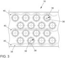
- the battery modules 4 each have a cell carrier (module carrier block) 16 as a cell connector ( 3 ).
- the or each battery cell 14 has a cylindrical cell housing 18 which is closed by means of a cell cover 20 at the end.
- An electrode coil 22 is arranged inside the cell housing 18 .
- the electrode coil 22 has two cell poles 24 , 26 , ie a positive pole 24 and a negative pole 26 .
- the positive pole 24 is in contact with the cell cover 20 .
- the negative pole 26 is on the opposite end of the cell housing 18 contacted to a housing base. In other words, the negative pole 26 is connected to the cell housing 18 .
- This means that the positive pole of the battery cell 14 is essentially formed by the cell cover 20 and the negative pole of the battery cell 14 is essentially formed by the cell housing 18 .
- the cell cover 20 and the cell housing 18 are expediently electrically insulated from one another.
- the positive pole 24 to be connected to the cell housing 18 and the negative pole 26 to be connected to the cell cover 20 .
- the cell housing 18 has an outside lateral surface 28 with an axial cell height 30 .
- An external thread 32 is introduced into the lateral surface 28 and extends essentially over the entire axial cell height 30 of the cell housing 18 .
- the cell carrier 16 shown only partially has a carrier body 34 in which a number of threaded holes 36 are introduced.
- the threaded bores 36 each have an internal thread 38 which is complementary to the external thread 32 .
- the threaded holes are in the 3 provided with reference numbers only as an example.
- the carrier body 34 is made, for example, from a phase change matrix material, the phase change matrix material retaining a fixed structure during a phase change.
- the carrier body 34 is here at least partially made of an electrically conductive material. In this case, for example, a stamped grid is integrated into the carrier body 34 and is guided to the threaded bores 36 or to their internal thread 38 .
- the battery cells 14 are screwed or screwed into the internal thread 38 of the threaded bores 36 of the cell carrier 16 by means of their external thread 32 . Due to the contacting of the cell pole 26 with the cell housing 18 and due to the electrically conductive material of the carrier body 34, the battery cells 14 are fastened positively to the cell carrier 16 on the one hand and electrically to one another on the other hand by being screwed in interconnected. In particular, the battery cells 14 are electrically conductively coupled to one another in an electrical parallel circuit.
- Coolant channels 40 which are integrated into the carrier body 34 , are routed around the threaded bores 36 .
- the coolant channels 40 are in the 3 shown in dotted lines.
- the coolant channels 40 are guided around the threaded bores 36 in a wave-like or meandering manner, so that each threaded bore 36 is at least partially surrounded or bordered by a coolant channel 40 .
- the coolant ducts 40 can be designed here, for example, as a continuous, that is to say one-piece coolant duct, or as separate, parallel coolant ducts.
- the coolant channels 40 are connected to a coolant circuit of the battery 2 and/or the motor vehicle, and a coolant or heat medium flows through them.
- the space-compact grid dimension of the threaded bores 36 and the phase change matrix material of the carrier body 34 as well as the coolant channels 40 result in a particularly effective, reliable and operationally safe temperature management of the battery cells 14, which enables high-performance temperature control of the battery cells 14 close to the cell during operation of the battery module 4 guaranteed.
Claims (9)
- Module de batterie (4), comprenant au moins un élément de batterie (14) et un support de cellule (16),- dans lequel l'élément de batterie (14) comprend un boîtier de cellule (18) cylindrique avec une surface d'enveloppe (28) côté extérieur,- dans lequel un filetage extérieur (32) est réalisé dans la surface d'enveloppe (28),- dans lequel le filetage extérieur (32) s'étend sensiblement sur toute la hauteur axiale (30) de la cellule du boîtier de cellule (18),- dans lequel le support de cellule (16) comprend au moins un trou fileté (36) avec un filetage intérieur (38), et- dans lequel le trou fileté (36) a une profondeur axiale suffisante pour que l'élément de batterie (14) soit entièrement vissé ou puisse être entièrement vissé.
- Module de batterie (4) selon la revendication 1,
caractérisé en ce
qu'un pôle de cellule (26) de la cellule (14) de batterie est monté sur le boîtier (18) de cellule. - Module de batterie (4) selon la revendication 1 ou 2,
caractérisé en ce
que le support de cellule (16) est fabriqué au moins partiellement d'un matériau électriquement conducteur. - Module de batterie (4) selon l'une des revendications 1 à 3,
caractérisé en ce
que l'élément de batterie (14) est en contact électriquement conducteur à l'état vissé. - Module de batterie (4) selon l'une des revendications 1 à 4,
caractérisé en ce
qu'un canal de réfrigérant (40) est intégré dans le support de cellule (16), lequel est guidé autour du au moins un trou fileté (36). - Module de batterie (4) selon l'une des revendications 1 à 5,
caractérisé en ce
que, dans la zone du trou fileté (36), un matériau à changement de phase est introduit dans le support de cellule (16), lequel conserve une structure solide lors d'une transition de phase. - Module de batterie (4) selon l'une des revendications 1 à 6,
caractérisé en ce
qu'un certain nombre de trous filetés (36) sont disposés dans le support de cellule (16) selon une dimension de trame rectangulaire centrée ou hexagonale. - Elément de batterie (14) pour un module de batterie (4) selon l'une des revendications 1 à 7, comprenant un boîtier de cellule (18) cylindrique, qui comprend une surface d'enveloppe (28) côté extérieur, dans laquelle est réalisé un filetage extérieur (32), le filetage extérieur (32) s'étendant sensiblement sur toute la hauteur axiale (30) de l'élément du boîtier de cellule (18).
- Véhicule automobile à propulsion ou à entraînement électrique, comprenant une batterie de véhicule (2) avec un module de batterie (4) selon l'une des revendications 1 à 7.
Applications Claiming Priority (1)
| Application Number | Priority Date | Filing Date | Title |
|---|---|---|---|
| DE102019207207.0A DE102019207207A1 (de) | 2019-05-17 | 2019-05-17 | Batteriemodul für ein Kraftfahrzeug |
Publications (2)
| Publication Number | Publication Date |
|---|---|
| EP3739660A1 EP3739660A1 (fr) | 2020-11-18 |
| EP3739660B1 true EP3739660B1 (fr) | 2023-07-12 |
Family
ID=70682642
Family Applications (1)
| Application Number | Title | Priority Date | Filing Date |
|---|---|---|---|
| EP20174185.7A Active EP3739660B1 (fr) | 2019-05-17 | 2020-05-12 | Module de batterie pour un véhicule automobile |
Country Status (4)
| Country | Link |
|---|---|
| US (1) | US20200365932A1 (fr) |
| EP (1) | EP3739660B1 (fr) |
| CN (1) | CN111952496A (fr) |
| DE (1) | DE102019207207A1 (fr) |
Families Citing this family (8)
| Publication number | Priority date | Publication date | Assignee | Title |
|---|---|---|---|---|
| US11527798B2 (en) * | 2020-08-26 | 2022-12-13 | Bae Systems Information And Electronic Systems Integration Inc. | Battery mounting mechanism |
| DE102020210927A1 (de) | 2020-08-31 | 2022-03-03 | Robert Bosch Gesellschaft mit beschränkter Haftung | Kühlsystem für mindestens eine Batterie |
| FR3118315A1 (fr) * | 2020-12-22 | 2022-06-24 | Airbus Defence And Space Sas | Dispositif pour la protection et le refroidissement d’une batterie. |
| DE102021110025A1 (de) | 2021-04-21 | 2022-10-27 | Dr. Ing. H.C. F. Porsche Aktiengesellschaft | Batteriezelle-Befestigungsanordnung und Elektrofahrzeug |
| DE102021110914A1 (de) | 2021-04-28 | 2022-11-03 | Audi Aktiengesellschaft | Verfahren zum Demontieren einer Batterieanordnung und Demontageanordnung |
| DE102021207360A1 (de) * | 2021-07-12 | 2023-01-12 | Robert Bosch Gesellschaft mit beschränkter Haftung | Batteriezelle, Batteriezellenadapter, System mit Batteriezelle und Batteriezellenadapter, sowie Batteriemodulzellenhalter |
| DE102022111769B4 (de) * | 2022-05-11 | 2024-01-18 | Rheinisch-Westfälische Technische Hochschule Aachen, Körperschaft des öffentlichen Rechts | Batterievorrichtung |
| DE102022002480A1 (de) | 2022-07-07 | 2024-01-18 | Mercedes-Benz Group AG | Batteriezelle für ein Batteriemodul eines elektrischen Energiespeichers sowie Batteriemodul |
Family Cites Families (15)
| Publication number | Priority date | Publication date | Assignee | Title |
|---|---|---|---|---|
| JP3312852B2 (ja) * | 1996-09-26 | 2002-08-12 | 松下電器産業株式会社 | 蓄電池電源装置 |
| US8273474B2 (en) * | 2000-02-29 | 2012-09-25 | Illinois Institute Of Technology | Battery system thermal management |
| JP3759872B2 (ja) | 2000-05-12 | 2006-03-29 | 本田技研工業株式会社 | セルモジュール |
| US20060113965A1 (en) * | 2004-11-30 | 2006-06-01 | Yoon-Cheol Jeon | Secondary battery module |
| JP4182451B1 (ja) * | 2007-07-23 | 2008-11-19 | トヨタ自動車株式会社 | 組電池 |
| CN102165625B (zh) * | 2008-08-14 | 2015-11-25 | 江森自控帅福得先进能源动力系统有限责任公司 | 具有密封的放气室的电池模块 |
| US20120107662A1 (en) * | 2010-10-29 | 2012-05-03 | Roemmler Mike | Thermal management matrix |
| JPWO2012093456A1 (ja) * | 2011-01-06 | 2014-06-09 | パナソニック株式会社 | 電池モジュール |
| WO2012164832A1 (fr) * | 2011-05-31 | 2012-12-06 | パナソニック株式会社 | Bloc de cellules |
| JP5919065B2 (ja) * | 2012-03-30 | 2016-05-18 | 本田技研工業株式会社 | 電動車両における円柱型バッテリの搭載構造 |
| DE102015210671A1 (de) | 2015-06-11 | 2016-12-15 | Robert Bosch Gmbh | Batteriezelle mit einem innerhalb eines zweiten Terminals angeordneten ersten Terminal |
| CN106410080A (zh) * | 2016-09-27 | 2017-02-15 | 深圳市沃特玛电池有限公司 | 一种电池组件 |
| CN206558654U (zh) * | 2017-02-23 | 2017-10-13 | 深圳市沃特玛电池有限公司 | 一种新型的动力电池模组散热结构 |
| CN207233784U (zh) * | 2017-08-17 | 2018-04-13 | 深圳市沃特玛电池有限公司 | 一种电池结构 |
| WO2019241871A1 (fr) * | 2018-06-22 | 2019-12-26 | Charger Industries Canada Limited Partnership | Batterie à amortissement de vibration, contenant de batterie et bloc-batterie destinés à être utilisés en fond de trou |
-
2019
- 2019-05-17 DE DE102019207207.0A patent/DE102019207207A1/de active Pending
-
2020
- 2020-05-12 EP EP20174185.7A patent/EP3739660B1/fr active Active
- 2020-05-18 CN CN202010418223.5A patent/CN111952496A/zh active Pending
- 2020-05-18 US US16/876,743 patent/US20200365932A1/en active Pending
Also Published As
| Publication number | Publication date |
|---|---|
| CN111952496A (zh) | 2020-11-17 |
| US20200365932A1 (en) | 2020-11-19 |
| DE102019207207A1 (de) | 2020-11-19 |
| EP3739660A1 (fr) | 2020-11-18 |
Similar Documents
| Publication | Publication Date | Title |
|---|---|---|
| EP3739660B1 (fr) | Module de batterie pour un véhicule automobile | |
| DE102008059967B4 (de) | Batterie und Verfahren zur Herstellung einer Batterie mit einer in einem Batteriegehäuse angeordneten Wärmeleitplatte | |
| DE102008059969B4 (de) | Vorrichtung zur Kühlung einer Batterie und Verwendung der Vorrichtung | |
| DE102008034868B4 (de) | Batterie mit einer in einem Batteriegehäuse angeordneten Wärmeleitplatte zum Temperieren der Batterie | |
| DE102010013025A1 (de) | Batterie und Verfahren zur Herstellung einer Batterie mit einer in einem Batteriegehäuse angeordneten Kühlplatte | |
| EP2854212A1 (fr) | Dispositif de chauffage et de refroidissement pour une batterie | |
| DE102008059947A1 (de) | Batterie mit einer in einem Batteriegehäuse angeordneten Wärmeleitplatte und daran direkt montierten elektronischen Bauelementen zum Temperieren der Batterie | |
| WO2019161876A1 (fr) | Système mécanique et thermique pour batterie modulaire à composants électroniques de puissance | |
| DE102008010837A1 (de) | Batterie mit einer in einem Batteriegehäuse angeordneten Wärmeleitplatte zum Temperieren der Batterie | |
| WO2016155846A1 (fr) | Bloc-batterie, et procédé de fabrication d'un bloc-batterie | |
| WO2008106946A2 (fr) | Cellule d'accumulation d'énergie à plaque conductrice de chaleur | |
| DE102009035470A1 (de) | Batterie und Verfahren zu deren Herstellung | |
| DE102012211180A1 (de) | Energiespeichermodul aus mehreren prismatischen Speicherzellen | |
| DE102012215205A1 (de) | Zellenverbinder, Batteriezellenmodul, Batterie, Verfahren zur Herstellung eines Batteriezellenmoduls und Kraftfahrzeug | |
| WO2010012338A1 (fr) | Batterie, en particulier batterie de véhicule | |
| DE102007063269A1 (de) | Batteriemodul mit mehreren Einzelzellen | |
| WO2016037763A1 (fr) | Dispositif d'équilibrage de température d'une unité d'alimentation en énergie électrique | |
| EP2457276A1 (fr) | Accumulateur d'énergie électrochimique et procédé de refroidissement et de chauffage d'un accumulateur d'énergie électrochimique | |
| WO2009103466A1 (fr) | Batterie comportant une plaque conductrice de chaleur disposée dans un boîtier de batterie et destinée à thermoréguler la batterie, procédé de fabrication d'une batterie | |
| EP2735039B1 (fr) | Système de mise en contact électrique des éléments d'un accumulateur d'énergie | |
| WO2015121118A1 (fr) | Dispositif accumulateur d'énergie électrique et procédé de dissipation thermique d'un dispositif accumulateur d'énergie électrique | |
| DE102019200817A1 (de) | Kühleinrichtung zur Kühlung von Batteriezellen, Batterie und Kraftfahrzeug | |
| EP2909873B1 (fr) | Cellule accumulatrice d'énergie et module accumulateur d'énergie | |
| DE102015016599A1 (de) | Wärmeleitanordnung und elektrische Batterie | |
| EP3465797B1 (fr) | Batterie avec des sections de batterie et des éléments de contact à ces sections |
Legal Events
| Date | Code | Title | Description |
|---|---|---|---|
| PUAI | Public reference made under article 153(3) epc to a published international application that has entered the european phase |
Free format text: ORIGINAL CODE: 0009012 |
|
| STAA | Information on the status of an ep patent application or granted ep patent |
Free format text: STATUS: THE APPLICATION HAS BEEN PUBLISHED |
|
| AK | Designated contracting states |
Kind code of ref document: A1 Designated state(s): AL AT BE BG CH CY CZ DE DK EE ES FI FR GB GR HR HU IE IS IT LI LT LU LV MC MK MT NL NO PL PT RO RS SE SI SK SM TR |
|
| AX | Request for extension of the european patent |
Extension state: BA ME |
|
| STAA | Information on the status of an ep patent application or granted ep patent |
Free format text: STATUS: REQUEST FOR EXAMINATION WAS MADE |
|
| 17P | Request for examination filed |
Effective date: 20210518 |
|
| RAV | Requested validation state of the european patent: fee paid |
Extension state: KH Effective date: 20210518 Extension state: MA Effective date: 20210518 Extension state: MD Effective date: 20210518 Extension state: TN Effective date: 20210518 |
|
| RAX | Requested extension states of the european patent have changed |
Extension state: BA Payment date: 20210518 Extension state: ME Payment date: 20210518 |
|
| RBV | Designated contracting states (corrected) |
Designated state(s): AL AT BE BG CH CY CZ DE DK EE ES FI FR GB GR HR HU IE IS IT LI LT LU LV MC MK MT NL NO PL PT RO RS SE SI SK SM TR |
|
| REG | Reference to a national code |
Ref country code: DE Ref legal event code: R079 Ref document number: 502020004105 Country of ref document: DE Free format text: PREVIOUS MAIN CLASS: H01M0002100000 Ipc: H01M0010040000 Ref country code: DE Ref legal event code: R079 Free format text: PREVIOUS MAIN CLASS: H01M0002100000 Ipc: H01M0010040000 |
|
| GRAP | Despatch of communication of intention to grant a patent |
Free format text: ORIGINAL CODE: EPIDOSNIGR1 |
|
| STAA | Information on the status of an ep patent application or granted ep patent |
Free format text: STATUS: GRANT OF PATENT IS INTENDED |
|
| RIC1 | Information provided on ipc code assigned before grant |
Ipc: B60L 50/64 20190101ALN20230123BHEP Ipc: B60K 1/04 20060101ALN20230123BHEP Ipc: H01M 50/249 20210101ALI20230123BHEP Ipc: H01M 50/50 20210101ALI20230123BHEP Ipc: H01M 50/24 20210101ALI20230123BHEP Ipc: H01M 10/6557 20140101ALI20230123BHEP Ipc: H01M 10/655 20140101ALI20230123BHEP Ipc: H01M 50/213 20210101ALI20230123BHEP Ipc: H01M 10/643 20140101ALI20230123BHEP Ipc: H01M 10/625 20140101ALI20230123BHEP Ipc: H01M 50/107 20210101ALI20230123BHEP Ipc: H01M 10/613 20140101ALI20230123BHEP Ipc: H01M 10/04 20060101AFI20230123BHEP |
|
| INTG | Intention to grant announced |
Effective date: 20230216 |
|
| GRAS | Grant fee paid |
Free format text: ORIGINAL CODE: EPIDOSNIGR3 |
|
| GRAA | (expected) grant |
Free format text: ORIGINAL CODE: 0009210 |
|
| STAA | Information on the status of an ep patent application or granted ep patent |
Free format text: STATUS: THE PATENT HAS BEEN GRANTED |
|
| AK | Designated contracting states |
Kind code of ref document: B1 Designated state(s): AL AT BE BG CH CY CZ DE DK EE ES FI FR GB GR HR HU IE IS IT LI LT LU LV MC MK MT NL NO PL PT RO RS SE SI SK SM TR |
|
| REG | Reference to a national code |
Ref country code: CH Ref legal event code: EP |
|
| REG | Reference to a national code |
Ref country code: IE Ref legal event code: FG4D Free format text: LANGUAGE OF EP DOCUMENT: GERMAN |
|
| REG | Reference to a national code |
Ref country code: DE Ref legal event code: R096 Ref document number: 502020004105 Country of ref document: DE |
|
| P01 | Opt-out of the competence of the unified patent court (upc) registered |
Effective date: 20230713 |
|
| REG | Reference to a national code |
Ref country code: LT Ref legal event code: MG9D |
|
| REG | Reference to a national code |
Ref country code: NL Ref legal event code: MP Effective date: 20230712 |
|
| PG25 | Lapsed in a contracting state [announced via postgrant information from national office to epo] |
Ref country code: NL Free format text: LAPSE BECAUSE OF FAILURE TO SUBMIT A TRANSLATION OF THE DESCRIPTION OR TO PAY THE FEE WITHIN THE PRESCRIBED TIME-LIMIT Effective date: 20230712 |
|
| PG25 | Lapsed in a contracting state [announced via postgrant information from national office to epo] |
Ref country code: GR Free format text: LAPSE BECAUSE OF FAILURE TO SUBMIT A TRANSLATION OF THE DESCRIPTION OR TO PAY THE FEE WITHIN THE PRESCRIBED TIME-LIMIT Effective date: 20231013 |
|
| PG25 | Lapsed in a contracting state [announced via postgrant information from national office to epo] |
Ref country code: ES Free format text: LAPSE BECAUSE OF FAILURE TO SUBMIT A TRANSLATION OF THE DESCRIPTION OR TO PAY THE FEE WITHIN THE PRESCRIBED TIME-LIMIT Effective date: 20230712 |
|
| PG25 | Lapsed in a contracting state [announced via postgrant information from national office to epo] |
Ref country code: IS Free format text: LAPSE BECAUSE OF FAILURE TO SUBMIT A TRANSLATION OF THE DESCRIPTION OR TO PAY THE FEE WITHIN THE PRESCRIBED TIME-LIMIT Effective date: 20231112 |
|
| PG25 | Lapsed in a contracting state [announced via postgrant information from national office to epo] |
Ref country code: SE Free format text: LAPSE BECAUSE OF FAILURE TO SUBMIT A TRANSLATION OF THE DESCRIPTION OR TO PAY THE FEE WITHIN THE PRESCRIBED TIME-LIMIT Effective date: 20230712 Ref country code: RS Free format text: LAPSE BECAUSE OF FAILURE TO SUBMIT A TRANSLATION OF THE DESCRIPTION OR TO PAY THE FEE WITHIN THE PRESCRIBED TIME-LIMIT Effective date: 20230712 Ref country code: PT Free format text: LAPSE BECAUSE OF FAILURE TO SUBMIT A TRANSLATION OF THE DESCRIPTION OR TO PAY THE FEE WITHIN THE PRESCRIBED TIME-LIMIT Effective date: 20231113 Ref country code: NO Free format text: LAPSE BECAUSE OF FAILURE TO SUBMIT A TRANSLATION OF THE DESCRIPTION OR TO PAY THE FEE WITHIN THE PRESCRIBED TIME-LIMIT Effective date: 20231012 Ref country code: LV Free format text: LAPSE BECAUSE OF FAILURE TO SUBMIT A TRANSLATION OF THE DESCRIPTION OR TO PAY THE FEE WITHIN THE PRESCRIBED TIME-LIMIT Effective date: 20230712 Ref country code: LT Free format text: LAPSE BECAUSE OF FAILURE TO SUBMIT A TRANSLATION OF THE DESCRIPTION OR TO PAY THE FEE WITHIN THE PRESCRIBED TIME-LIMIT Effective date: 20230712 Ref country code: IS Free format text: LAPSE BECAUSE OF FAILURE TO SUBMIT A TRANSLATION OF THE DESCRIPTION OR TO PAY THE FEE WITHIN THE PRESCRIBED TIME-LIMIT Effective date: 20231112 Ref country code: HR Free format text: LAPSE BECAUSE OF FAILURE TO SUBMIT A TRANSLATION OF THE DESCRIPTION OR TO PAY THE FEE WITHIN THE PRESCRIBED TIME-LIMIT Effective date: 20230712 Ref country code: GR Free format text: LAPSE BECAUSE OF FAILURE TO SUBMIT A TRANSLATION OF THE DESCRIPTION OR TO PAY THE FEE WITHIN THE PRESCRIBED TIME-LIMIT Effective date: 20231013 Ref country code: FI Free format text: LAPSE BECAUSE OF FAILURE TO SUBMIT A TRANSLATION OF THE DESCRIPTION OR TO PAY THE FEE WITHIN THE PRESCRIBED TIME-LIMIT Effective date: 20230712 Ref country code: ES Free format text: LAPSE BECAUSE OF FAILURE TO SUBMIT A TRANSLATION OF THE DESCRIPTION OR TO PAY THE FEE WITHIN THE PRESCRIBED TIME-LIMIT Effective date: 20230712 |
|
| PG25 | Lapsed in a contracting state [announced via postgrant information from national office to epo] |
Ref country code: PL Free format text: LAPSE BECAUSE OF FAILURE TO SUBMIT A TRANSLATION OF THE DESCRIPTION OR TO PAY THE FEE WITHIN THE PRESCRIBED TIME-LIMIT Effective date: 20230712 |
|
| PG25 | Lapsed in a contracting state [announced via postgrant information from national office to epo] |
Ref country code: SM Free format text: LAPSE BECAUSE OF FAILURE TO SUBMIT A TRANSLATION OF THE DESCRIPTION OR TO PAY THE FEE WITHIN THE PRESCRIBED TIME-LIMIT Effective date: 20230712 Ref country code: RO Free format text: LAPSE BECAUSE OF FAILURE TO SUBMIT A TRANSLATION OF THE DESCRIPTION OR TO PAY THE FEE WITHIN THE PRESCRIBED TIME-LIMIT Effective date: 20230712 Ref country code: EE Free format text: LAPSE BECAUSE OF FAILURE TO SUBMIT A TRANSLATION OF THE DESCRIPTION OR TO PAY THE FEE WITHIN THE PRESCRIBED TIME-LIMIT Effective date: 20230712 Ref country code: DK Free format text: LAPSE BECAUSE OF FAILURE TO SUBMIT A TRANSLATION OF THE DESCRIPTION OR TO PAY THE FEE WITHIN THE PRESCRIBED TIME-LIMIT Effective date: 20230712 Ref country code: CZ Free format text: LAPSE BECAUSE OF FAILURE TO SUBMIT A TRANSLATION OF THE DESCRIPTION OR TO PAY THE FEE WITHIN THE PRESCRIBED TIME-LIMIT Effective date: 20230712 Ref country code: SK Free format text: LAPSE BECAUSE OF FAILURE TO SUBMIT A TRANSLATION OF THE DESCRIPTION OR TO PAY THE FEE WITHIN THE PRESCRIBED TIME-LIMIT Effective date: 20230712 |
|
| VS25 | Lapsed in a validation state [announced via postgrant information from nat. office to epo] |
Ref country code: MD Free format text: LAPSE BECAUSE OF FAILURE TO SUBMIT A TRANSLATION OF THE DESCRIPTION OR TO PAY THE FEE WITHIN THE PRESCRIBED TIME-LIMIT Effective date: 20230712 |