EP3739228B1 - Structure de pression dynamique de ventilateur comportant un cadre en plastique formé intégralement autour d'un palier en poudre de métal fritté contenant de l'huile - Google Patents
Structure de pression dynamique de ventilateur comportant un cadre en plastique formé intégralement autour d'un palier en poudre de métal fritté contenant de l'huile Download PDFInfo
- Publication number
- EP3739228B1 EP3739228B1 EP20157103.1A EP20157103A EP3739228B1 EP 3739228 B1 EP3739228 B1 EP 3739228B1 EP 20157103 A EP20157103 A EP 20157103A EP 3739228 B1 EP3739228 B1 EP 3739228B1
- Authority
- EP
- European Patent Office
- Prior art keywords
- dynamic pressure
- oil
- metal powder
- sintered metal
- containing sintered
- Prior art date
- Legal status (The legal status is an assumption and is not a legal conclusion. Google has not performed a legal analysis and makes no representation as to the accuracy of the status listed.)
- Active
Links
- 239000002184 metal Substances 0.000 title claims description 40
- 239000000843 powder Substances 0.000 title claims description 40
- 239000004033 plastic Substances 0.000 title claims description 23
- 238000003780 insertion Methods 0.000 claims description 17
- 230000037431 insertion Effects 0.000 claims description 17
- 230000002093 peripheral effect Effects 0.000 claims description 3
- 239000003921 oil Substances 0.000 description 43
- 238000003825 pressing Methods 0.000 description 3
- 229910000976 Electrical steel Inorganic materials 0.000 description 2
- 238000000034 method Methods 0.000 description 2
- 230000000717 retained effect Effects 0.000 description 2
- 230000007547 defect Effects 0.000 description 1
- 238000010586 diagram Methods 0.000 description 1
- 230000000694 effects Effects 0.000 description 1
- 239000012530 fluid Substances 0.000 description 1
- 238000004519 manufacturing process Methods 0.000 description 1
- 239000002991 molded plastic Substances 0.000 description 1
- 238000003860 storage Methods 0.000 description 1
Images


Classifications
-
- F—MECHANICAL ENGINEERING; LIGHTING; HEATING; WEAPONS; BLASTING
- F16—ENGINEERING ELEMENTS AND UNITS; GENERAL MEASURES FOR PRODUCING AND MAINTAINING EFFECTIVE FUNCTIONING OF MACHINES OR INSTALLATIONS; THERMAL INSULATION IN GENERAL
- F16C—SHAFTS; FLEXIBLE SHAFTS; ELEMENTS OR CRANKSHAFT MECHANISMS; ROTARY BODIES OTHER THAN GEARING ELEMENTS; BEARINGS
- F16C33/00—Parts of bearings; Special methods for making bearings or parts thereof
- F16C33/02—Parts of sliding-contact bearings
- F16C33/04—Brasses; Bushes; Linings
- F16C33/06—Sliding surface mainly made of metal
- F16C33/10—Construction relative to lubrication
- F16C33/1025—Construction relative to lubrication with liquid, e.g. oil, as lubricant
- F16C33/103—Construction relative to lubrication with liquid, e.g. oil, as lubricant retained in or near the bearing
- F16C33/104—Construction relative to lubrication with liquid, e.g. oil, as lubricant retained in or near the bearing in a porous body, e.g. oil impregnated sintered sleeve
-
- F—MECHANICAL ENGINEERING; LIGHTING; HEATING; WEAPONS; BLASTING
- F04—POSITIVE - DISPLACEMENT MACHINES FOR LIQUIDS; PUMPS FOR LIQUIDS OR ELASTIC FLUIDS
- F04D—NON-POSITIVE-DISPLACEMENT PUMPS
- F04D29/00—Details, component parts, or accessories
- F04D29/05—Shafts or bearings, or assemblies thereof, specially adapted for elastic fluid pumps
- F04D29/056—Bearings
-
- F—MECHANICAL ENGINEERING; LIGHTING; HEATING; WEAPONS; BLASTING
- F04—POSITIVE - DISPLACEMENT MACHINES FOR LIQUIDS; PUMPS FOR LIQUIDS OR ELASTIC FLUIDS
- F04D—NON-POSITIVE-DISPLACEMENT PUMPS
- F04D25/00—Pumping installations or systems
- F04D25/02—Units comprising pumps and their driving means
- F04D25/06—Units comprising pumps and their driving means the pump being electrically driven
- F04D25/0606—Units comprising pumps and their driving means the pump being electrically driven the electric motor being specially adapted for integration in the pump
- F04D25/0613—Units comprising pumps and their driving means the pump being electrically driven the electric motor being specially adapted for integration in the pump the electric motor being of the inside-out type, i.e. the rotor is arranged radially outside a central stator
- F04D25/062—Details of the bearings
-
- F—MECHANICAL ENGINEERING; LIGHTING; HEATING; WEAPONS; BLASTING
- F04—POSITIVE - DISPLACEMENT MACHINES FOR LIQUIDS; PUMPS FOR LIQUIDS OR ELASTIC FLUIDS
- F04D—NON-POSITIVE-DISPLACEMENT PUMPS
- F04D29/00—Details, component parts, or accessories
- F04D29/06—Lubrication
- F04D29/063—Lubrication specially adapted for elastic fluid pumps
-
- F—MECHANICAL ENGINEERING; LIGHTING; HEATING; WEAPONS; BLASTING
- F04—POSITIVE - DISPLACEMENT MACHINES FOR LIQUIDS; PUMPS FOR LIQUIDS OR ELASTIC FLUIDS
- F04D—NON-POSITIVE-DISPLACEMENT PUMPS
- F04D29/00—Details, component parts, or accessories
- F04D29/40—Casings; Connections of working fluid
-
- F—MECHANICAL ENGINEERING; LIGHTING; HEATING; WEAPONS; BLASTING
- F04—POSITIVE - DISPLACEMENT MACHINES FOR LIQUIDS; PUMPS FOR LIQUIDS OR ELASTIC FLUIDS
- F04D—NON-POSITIVE-DISPLACEMENT PUMPS
- F04D29/00—Details, component parts, or accessories
- F04D29/66—Combating cavitation, whirls, noise, vibration or the like; Balancing
-
- F—MECHANICAL ENGINEERING; LIGHTING; HEATING; WEAPONS; BLASTING
- F16—ENGINEERING ELEMENTS AND UNITS; GENERAL MEASURES FOR PRODUCING AND MAINTAINING EFFECTIVE FUNCTIONING OF MACHINES OR INSTALLATIONS; THERMAL INSULATION IN GENERAL
- F16C—SHAFTS; FLEXIBLE SHAFTS; ELEMENTS OR CRANKSHAFT MECHANISMS; ROTARY BODIES OTHER THAN GEARING ELEMENTS; BEARINGS
- F16C17/00—Sliding-contact bearings for exclusively rotary movement
- F16C17/02—Sliding-contact bearings for exclusively rotary movement for radial load only
-
- F—MECHANICAL ENGINEERING; LIGHTING; HEATING; WEAPONS; BLASTING
- F16—ENGINEERING ELEMENTS AND UNITS; GENERAL MEASURES FOR PRODUCING AND MAINTAINING EFFECTIVE FUNCTIONING OF MACHINES OR INSTALLATIONS; THERMAL INSULATION IN GENERAL
- F16C—SHAFTS; FLEXIBLE SHAFTS; ELEMENTS OR CRANKSHAFT MECHANISMS; ROTARY BODIES OTHER THAN GEARING ELEMENTS; BEARINGS
- F16C33/00—Parts of bearings; Special methods for making bearings or parts thereof
- F16C33/02—Parts of sliding-contact bearings
- F16C33/04—Brasses; Bushes; Linings
- F16C33/06—Sliding surface mainly made of metal
- F16C33/10—Construction relative to lubrication
- F16C33/1025—Construction relative to lubrication with liquid, e.g. oil, as lubricant
- F16C33/106—Details of distribution or circulation inside the bearings, e.g. details of the bearing surfaces to affect flow or pressure of the liquid
- F16C33/107—Grooves for generating pressure
-
- F—MECHANICAL ENGINEERING; LIGHTING; HEATING; WEAPONS; BLASTING
- F16—ENGINEERING ELEMENTS AND UNITS; GENERAL MEASURES FOR PRODUCING AND MAINTAINING EFFECTIVE FUNCTIONING OF MACHINES OR INSTALLATIONS; THERMAL INSULATION IN GENERAL
- F16C—SHAFTS; FLEXIBLE SHAFTS; ELEMENTS OR CRANKSHAFT MECHANISMS; ROTARY BODIES OTHER THAN GEARING ELEMENTS; BEARINGS
- F16C33/00—Parts of bearings; Special methods for making bearings or parts thereof
- F16C33/02—Parts of sliding-contact bearings
- F16C33/04—Brasses; Bushes; Linings
- F16C33/06—Sliding surface mainly made of metal
- F16C33/10—Construction relative to lubrication
- F16C33/1095—Construction relative to lubrication with solids as lubricant, e.g. dry coatings, powder
-
- F—MECHANICAL ENGINEERING; LIGHTING; HEATING; WEAPONS; BLASTING
- F16—ENGINEERING ELEMENTS AND UNITS; GENERAL MEASURES FOR PRODUCING AND MAINTAINING EFFECTIVE FUNCTIONING OF MACHINES OR INSTALLATIONS; THERMAL INSULATION IN GENERAL
- F16C—SHAFTS; FLEXIBLE SHAFTS; ELEMENTS OR CRANKSHAFT MECHANISMS; ROTARY BODIES OTHER THAN GEARING ELEMENTS; BEARINGS
- F16C17/00—Sliding-contact bearings for exclusively rotary movement
- F16C17/10—Sliding-contact bearings for exclusively rotary movement for both radial and axial load
-
- F—MECHANICAL ENGINEERING; LIGHTING; HEATING; WEAPONS; BLASTING
- F16—ENGINEERING ELEMENTS AND UNITS; GENERAL MEASURES FOR PRODUCING AND MAINTAINING EFFECTIVE FUNCTIONING OF MACHINES OR INSTALLATIONS; THERMAL INSULATION IN GENERAL
- F16C—SHAFTS; FLEXIBLE SHAFTS; ELEMENTS OR CRANKSHAFT MECHANISMS; ROTARY BODIES OTHER THAN GEARING ELEMENTS; BEARINGS
- F16C2220/00—Shaping
- F16C2220/20—Shaping by sintering pulverised material, e.g. powder metallurgy
-
- F—MECHANICAL ENGINEERING; LIGHTING; HEATING; WEAPONS; BLASTING
- F16—ENGINEERING ELEMENTS AND UNITS; GENERAL MEASURES FOR PRODUCING AND MAINTAINING EFFECTIVE FUNCTIONING OF MACHINES OR INSTALLATIONS; THERMAL INSULATION IN GENERAL
- F16C—SHAFTS; FLEXIBLE SHAFTS; ELEMENTS OR CRANKSHAFT MECHANISMS; ROTARY BODIES OTHER THAN GEARING ELEMENTS; BEARINGS
- F16C2360/00—Engines or pumps
- F16C2360/46—Fans, e.g. ventilators
Definitions
- the present disclosure generally relates to a fan. More particularly, the present disclosure relates to a dynamic pressure structure of a fan.
- a fan is usually mounted on a frame equipped with a motor structure such as silicon steel sheets and magnets, and a bearing is disposed at the center of the frame for pivoting the axial shaft of the fan blade so that the fan blade can be smoothly rotated.
- a motor structure such as silicon steel sheets and magnets
- US 2011/0095627 A1 relates to an integrally molded plastic fan motor frame and sintered oil-impregnated bearing structure.
- US 2010/0247008 A1 relates to a fluid dynamic bearing.
- US2011/0095627 A1 discloses a fan dynamic pressure structure according to the preamble of claim 1.
- the oil-containing sintered metal powder bearing and a plastic frame are provided for assembling a conventional combination structure of the oil-containing sintered metal powder bearing and the plastic frame. Then, the oil-containing sintered metal powder bearing is press-fitted into the middle tube of the plastic frame.
- this kind of combination structure has the following disadvantages: the press-fit working time and manpower are increased, the pressing force is likely to cause damage to the oil-containing sintered metal powder bearing and the middle tube of the plastic frame so as to increase the defect rate, the pressing force is likely to cause deformation of the middle tube and the oil-containing sintered metal powder bearing, the strong pressing force may also deform the inner wall of the shaft hole of the oil-containing sintered metal powder bearing, and therefore the axial shaft may cause the structural friction with the foregoing inner or outer deformation and result in oil leakage and oil squeaking so as to cause the axial shaft to be stuck.
- a retaining ring is embedded in the protruding end of the bearing to prevent the fan blade out of the frame.
- the conventional retaining ring is a smooth C-shaped retaining ring with a poor oil storage effect.
- One objective of the embodiments of the present invention is to provide a fan dynamic pressure structure having a plastic frame integrally formed around an oil-containing sintered metal powder bearing to improve the function and efficiency of a fan.
- a fan dynamic pressure structure having a plastic frame integrally formed around an oil-containing sintered metal powder bearing includes an oil-containing sintered metal powder bearing, a plastic frame, a fan assembly and an annular dynamic pressure piece.
- the oil-containing sintered metal powder bearing has a bushing body, and the bushing body has a shaft hole in the center thereof.
- the plastic frame has a middle tube and a chassis, and the middle tube is integrally formed and surrounded a peripheral of the bushing body.
- the fan assembly has a plurality of fan blades and an axial shaft in which the axial shaft is disposed in a center of the fan assembly and the axial shaft penetrates through the shaft hole of the oil-containing sintered metal powder bearing and protrudes downwards, and the axial shaft has an annular groove.
- the annular dynamic pressure piece has an insertion hole and an annular body is surrounding the insertion hole. The insertion hole is fixed in the annular groove of the fan assembly, and the annular body has a plurality of curved radial dynamic pressure ditches on a surface adjacent to the oil-containing sintered metal powder bearing.
- the annular dynamic pressure piece has a plurality of curved radial dynamic pressure ditches on a surface opposite to the oil-containing sintered metal powder bearing.
- the axial shaft has a cone end portion at an end portion of the axial shaft.
- the cone end portion has an inclined surface
- the insertion hole of the annular dynamic pressure piece has an edge wall, on an inner wall of the insertion hole, corresponding to the inclined surface
- the damage and deformation, caused by the conventional press fit process, of the fan dynamic pressure structure having a plastic frame integrally formed around an oil-containing sintered metal powder bearing can be avoided because that the plastic frame is integrally formed around and joined together with the oil-containing sintered metal powder bearing.
- the oil film may formed between the surface of the annular dynamic pressure piece and the end surface of the oil-containing sintered metal powder bearing with the oil retained in the dynamic pressure ditches to allow the annular dynamic pressure piece stably rotates on the end surface of the oil-containing sintered metal powder bearing with acting force and reacting force and reduce the friction force therebetween so as to reduce the noise and vibration thereof and avoid the fan assembly escaping from the plastic frame.
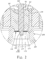
- a fan dynamic pressure structure having a plastic frame integrally formed around an oil-containing sintered metal powder bearing includes an oil-containing sintered metal powder bearing 100, a plastic frame 200, a fan assembly 300 and an annular dynamic pressure piece 400.
- the oil-containing sintered metal powder bearing 100 includes a bushing body 110, and the bushing body 110 includes a shaft hole 120 in the center thereof.
- the plastic frame 200 includes a middle tube 210 and a chassis 220 connected together.
- the middle tube 210 is integrally formed around the peripheral of the bushing body 110 of the oil-containing sintered metal powder bearing 100.
- the fan assembly 300 includes a plurality of fan blades 310 and an axial shaft 320.
- the axial shaft 320 is formed in the center of the fan assembly 300, and the axial shaft 320 penetrates through the shaft hole 120 of the oil-containing sintered metal powder bearing 100 and protrudes therefrom.
- the axial shaft 320 includes an annular groove 321.
- the axial shaft 320 has a cone end portion 322 at one end thereof to guide the annular dynamic pressure piece 400 to be fixed in the annular groove 321 of the axial shaft 320.
- the cone end portion 322 includes an inclined surface 323. Silicon steel sheets 230 and magnets 330 are equipped between the middle tube 210 of the plastic frame 200 and the fan assembly 300 for rotating the axial shaft 320 in the shaft hole 120 of the oil-containing sintered metal powder bearing 100.
- the annular dynamic pressure piece 400 includes an insertion hole 410 and an annular body 420 surrounding the insertion hole 410.
- the insertion hole 410 includes an inner wall having an edge wall 411 corresponding to the inclined surface 323 of the axial shaft 320.
- the edge wall 411 of the insertion hole 410 aligns with the inclined surface 323 of the axial shaft 320 and is guided by the cone end portion 322 of the axial shaft 320 so that the insertion hole 410 of the annular dynamic pressure piece 400 can smoothly engage with the annular groove 321 of the axial shaft 320.
- the annular dynamic pressure piece 400 is turned an predetermined angle to misalign the edge wall 411 of the annular dynamic pressure piece 400 with the inclined surface 323 of the axial shaft 320 so that the annular dynamic pressure piece 400 is firmly fixed in the annular groove 321 of the axial shaft 320 to reduce the drop rate thereof.
- a surface, adjacent to the oil-containing sintered metal powder bearing 100, and an opposite surface of the annular dynamic pressure piece 400 have a plurality of curved radial dynamic pressure ditches 421 to reserve the oil for forming oil films on the surfaces of the annular dynamic pressure piece 400.
- the damage and deformation, caused by the conventional press fit process, of the oil-containing sintered metal powder bearing 100 can be avoided because that the plastic frame 200 is integrally formed and joined together with the oil-containing sintered metal powder bearing 100.
- the oil film may formed between the surface of the annular dynamic pressure piece 400 and the end surface of the oil-containing sintered metal powder bearing 100 with the oil retained in the dynamic pressure ditches 421 to allow the annular dynamic pressure piece 400 stably rotates on the end surface of the oil-containing sintered metal powder bearing 100 with acting force and reacting force and reduce the friction force therebetween so as to reduce the noise and vibration thereof and avoid the fan assembly 300 escaping from the plastic frame.
Landscapes
- Engineering & Computer Science (AREA)
- General Engineering & Computer Science (AREA)
- Mechanical Engineering (AREA)
- Chemical & Material Sciences (AREA)
- Oil, Petroleum & Natural Gas (AREA)
- Sliding-Contact Bearings (AREA)
Claims (2)
- Structure de pression dynamique de ventilateur ayant un cadre en plastique (200) formé intégralement autour d'un palier à poudre métallique frittée contenant de l'huile (100), caractérisée en ce qu'elle comprend :un palier à poudre métallique frittée contenant de l'huile (100) ayant un corps de douille (110), le corps de douille (110) ayant un trou d'arbre (120) en son centre ;un cadre en plastique (200) ayant un tube médian (210) et un châssis (220), le tube médian (210) étant formé intégralement autour d'un périphérique du corps de douille (110) ;un ensemble ventilateur (300) ayant une pluralité de pales de ventilateur (310) et un arbre axial (320), l'arbre axial (320) étant disposé au centre de l'ensemble ventilateur (300) et l'arbre axial (320) pénétrant à travers le trou d'arbre (120) du palier à poudre métallique frittée contenant de l'huile (100) et faisant saillie vers le bas, et l'arbre axial (320) comprenant une rainure annulaire (321) ; etcaractérisée en ce que la structure de pression dynamique de ventilateur comprend en outre une pièce de pression dynamique annulaire (400) ayant un trou d'insertion (410) et un corps annulaire (420) entourant le trou d'insertion (410), le trou d'insertion (410) étant fixé dans la rainure annulaire (321) de l'ensemble ventilateur (300), et le corps annulaire (420) ayant une pluralité de fossés de pression dynamique radiale incurvés (421) formés sur une surface, adjacente au palier à poudre métallique frittée contenant de l'huile (100), du corps annulaire (420), l'arbre axial (320) comprenant une portion d'extrémité conique (322) à une portion d'extrémité de l'arbre axial (320), et la portion d'extrémité conique (322) comprenant une surface inclinée (323), et le trou d'insertion (410) de la pièce de pression dynamique annulaire (400) comprenant une paroi de bord (411), sur une paroi intérieure du trou d'insertion (410), correspondant à la surface inclinée (323), la paroi de bord (411) de la pièce de pression dynamique annulaire (400) se désalignant avec la surface inclinée (323) de l'arbre axial (320) après le trou d'insertion (410) entrant en prise dans la rainure annulaire (321).
- Structure de pression dynamique de ventilateur selon la revendication 1, dans laquelle la pièce de pression dynamique annulaire (400) a une pluralité de fossés de pression dynamique radiale incurvés (421) sur une surface, opposée au palier à poudre métallique frittée contenant de l'huile (100), du corps annulaire (420).
Priority Applications (1)
| Application Number | Priority Date | Filing Date | Title |
|---|---|---|---|
| PL20157103T PL3739228T3 (pl) | 2019-05-16 | 2020-02-13 | Konstrukcja ciśnienia dynamicznego wentylatora mająca ramę z tworzywa sztucznego integralnie uformowaną wokół łożyska olejowego ze spiekanych proszków metali |
Applications Claiming Priority (1)
| Application Number | Priority Date | Filing Date | Title |
|---|---|---|---|
| TW108206157U TWM582998U (zh) | 2019-05-16 | 2019-05-16 | 塑膠框體與含油金屬粉末軸承一體成型之風扇的動壓結構 |
Publications (2)
| Publication Number | Publication Date |
|---|---|
| EP3739228A1 EP3739228A1 (fr) | 2020-11-18 |
| EP3739228B1 true EP3739228B1 (fr) | 2022-03-30 |
Family
ID=68620883
Family Applications (1)
| Application Number | Title | Priority Date | Filing Date |
|---|---|---|---|
| EP20157103.1A Active EP3739228B1 (fr) | 2019-05-16 | 2020-02-13 | Structure de pression dynamique de ventilateur comportant un cadre en plastique formé intégralement autour d'un palier en poudre de métal fritté contenant de l'huile |
Country Status (8)
| Country | Link |
|---|---|
| US (1) | US11306727B2 (fr) |
| EP (1) | EP3739228B1 (fr) |
| DK (1) | DK3739228T3 (fr) |
| ES (1) | ES2913986T3 (fr) |
| HU (1) | HUE058658T2 (fr) |
| PL (1) | PL3739228T3 (fr) |
| PT (1) | PT3739228T (fr) |
| TW (1) | TWM582998U (fr) |
Family Cites Families (10)
| Publication number | Priority date | Publication date | Assignee | Title |
|---|---|---|---|---|
| US5264748A (en) * | 1990-05-24 | 1993-11-23 | Matsushita Electric Industrial Co., Ltd. | Axial-flow fan motor |
| JP3815028B2 (ja) * | 1998-02-27 | 2006-08-30 | 松下電器産業株式会社 | 電動機及びそれを用いたヒートシンク装置 |
| US6267567B1 (en) * | 2000-04-04 | 2001-07-31 | Hsieh Hsin-Mao | Cooling fan |
| GB2379560B (en) * | 2001-03-30 | 2005-12-14 | Sunonwealth Electr Mach Ind Co | Supporting structure for a rotor |
| TW519259U (en) * | 2001-08-31 | 2003-01-21 | Asia Vital Components Co Ltd | Improved structure of DC fan bearing fixation device |
| JP2006300245A (ja) * | 2005-04-21 | 2006-11-02 | Matsushita Electric Ind Co Ltd | 動圧流体軸受装置 |
| TW200734549A (en) * | 2006-03-10 | 2007-09-16 | Sunonwealth Electr Mach Ind Co | Cooling fan structure |
| TW200826419A (en) * | 2006-12-13 | 2008-06-16 | Sunonwealth Electr Mach Ind Co | A structure of motor |
| JP2010223377A (ja) * | 2009-03-24 | 2010-10-07 | Alphana Technology Co Ltd | 流体動圧軸受、流体動圧軸受の製造方法、回転機器およびディスク駆動装置 |
| TW201115029A (en) * | 2009-10-27 | 2011-05-01 | Bing-Lin Wang | Integrated structure for fan motor plastic frame and oil-containing powder bearing and manufacturing method thereof |
-
2019
- 2019-05-16 TW TW108206157U patent/TWM582998U/zh unknown
- 2019-10-02 US US16/591,606 patent/US11306727B2/en active Active
-
2020
- 2020-02-13 HU HUE20157103A patent/HUE058658T2/hu unknown
- 2020-02-13 PT PT201571031T patent/PT3739228T/pt unknown
- 2020-02-13 DK DK20157103.1T patent/DK3739228T3/da active
- 2020-02-13 ES ES20157103T patent/ES2913986T3/es active Active
- 2020-02-13 PL PL20157103T patent/PL3739228T3/pl unknown
- 2020-02-13 EP EP20157103.1A patent/EP3739228B1/fr active Active
Also Published As
| Publication number | Publication date |
|---|---|
| US11306727B2 (en) | 2022-04-19 |
| ES2913986T3 (es) | 2022-06-07 |
| HUE058658T2 (hu) | 2022-09-28 |
| US20200362872A1 (en) | 2020-11-19 |
| DK3739228T3 (da) | 2022-05-16 |
| EP3739228A1 (fr) | 2020-11-18 |
| PL3739228T3 (pl) | 2022-07-04 |
| PT3739228T (pt) | 2022-05-04 |
| TWM582998U (zh) | 2019-09-01 |
Similar Documents
| Publication | Publication Date | Title |
|---|---|---|
| US8256772B2 (en) | Lip type seal | |
| EP2476934B1 (fr) | Joint de type à lèvre | |
| JP2002013643A (ja) | シールスリーブ | |
| WO2014030742A1 (fr) | Dispositif de scellement hermétique | |
| JP2012112340A (ja) | ウォータポンプ | |
| JPWO2004090391A1 (ja) | リップ型シール | |
| US20100264763A1 (en) | Fluid dynamic bearing system and a spindle motor having a bearing system of this kind | |
| EP3739228B1 (fr) | Structure de pression dynamique de ventilateur comportant un cadre en plastique formé intégralement autour d'un palier en poudre de métal fritté contenant de l'huile | |
| US8272784B2 (en) | Sleeve bearing system | |
| EP3901479B1 (fr) | Moteur avec ensemble de paliers | |
| US7140777B2 (en) | Hydrodynamic bearing assembly | |
| WO2013125649A1 (fr) | Compresseur | |
| CN209925261U (zh) | 塑料框体与含油金属粉末轴承一体成型的风扇的动压结构 | |
| US10823186B2 (en) | Pump bearing retainer | |
| EP3786471A1 (fr) | Système de palier | |
| JP3236241U (ja) | プラスチックフレームと金属粉による含油軸受とが一体成形したファンの動圧構造 | |
| JP6607321B2 (ja) | シールリング、および、過給機 | |
| CN212455218U (zh) | 一种包含自适应金属阻尼器的空气轴承 | |
| JP5582608B2 (ja) | 軸封装置 | |
| WO2023189092A1 (fr) | Palier à feuilles et machine à fluide | |
| JP2024003437A (ja) | 密封装置 | |
| WO2020067119A1 (fr) | Roulement à billes avec joint résistant à la pression | |
| CN107989819B (zh) | 轴承结构及其散热风扇 | |
| JP5769866B2 (ja) | 圧縮機 | |
| JPH0925817A (ja) | ウォ−タポンプ用軸受 |
Legal Events
| Date | Code | Title | Description |
|---|---|---|---|
| PUAI | Public reference made under article 153(3) epc to a published international application that has entered the european phase |
Free format text: ORIGINAL CODE: 0009012 |
|
| STAA | Information on the status of an ep patent application or granted ep patent |
Free format text: STATUS: THE APPLICATION HAS BEEN PUBLISHED |
|
| AK | Designated contracting states |
Kind code of ref document: A1 Designated state(s): AL AT BE BG CH CY CZ DE DK EE ES FI FR GB GR HR HU IE IS IT LI LT LU LV MC MK MT NL NO PL PT RO RS SE SI SK SM TR |
|
| AX | Request for extension of the european patent |
Extension state: BA ME |
|
| STAA | Information on the status of an ep patent application or granted ep patent |
Free format text: STATUS: REQUEST FOR EXAMINATION WAS MADE |
|
| 17P | Request for examination filed |
Effective date: 20201229 |
|
| RBV | Designated contracting states (corrected) |
Designated state(s): AL AT BE BG CH CY CZ DE DK EE ES FI FR GB GR HR HU IE IS IT LI LT LU LV MC MK MT NL NO PL PT RO RS SE SI SK SM TR |
|
| GRAP | Despatch of communication of intention to grant a patent |
Free format text: ORIGINAL CODE: EPIDOSNIGR1 |
|
| STAA | Information on the status of an ep patent application or granted ep patent |
Free format text: STATUS: GRANT OF PATENT IS INTENDED |
|
| INTG | Intention to grant announced |
Effective date: 20210921 |
|
| GRAS | Grant fee paid |
Free format text: ORIGINAL CODE: EPIDOSNIGR3 |
|
| RAP1 | Party data changed (applicant data changed or rights of an application transferred) |
Owner name: 3D-FLRS INTERNATIONAL COMPANY LTD. |
|
| GRAA | (expected) grant |
Free format text: ORIGINAL CODE: 0009210 |
|
| STAA | Information on the status of an ep patent application or granted ep patent |
Free format text: STATUS: THE PATENT HAS BEEN GRANTED |
|
| GRAT | Correction requested after decision to grant or after decision to maintain patent in amended form |
Free format text: ORIGINAL CODE: EPIDOSNCDEC |
|
| AK | Designated contracting states |
Kind code of ref document: B1 Designated state(s): AL AT BE BG CH CY CZ DE DK EE ES FI FR GB GR HR HU IE IS IT LI LT LU LV MC MK MT NL NO PL PT RO RS SE SI SK SM TR |
|
| REG | Reference to a national code |
Ref country code: GB Ref legal event code: FG4D |
|
| REG | Reference to a national code |
Ref country code: CH Ref legal event code: EP |
|
| REG | Reference to a national code |
Ref country code: AT Ref legal event code: REF Ref document number: 1479454 Country of ref document: AT Kind code of ref document: T Effective date: 20220415 |
|
| REG | Reference to a national code |
Ref country code: DE Ref legal event code: R096 Ref document number: 602020002359 Country of ref document: DE |
|
| REG | Reference to a national code |
Ref country code: IE Ref legal event code: FG4D |
|
| REG | Reference to a national code |
Ref country code: PT Ref legal event code: SC4A Ref document number: 3739228 Country of ref document: PT Date of ref document: 20220504 Kind code of ref document: T Free format text: AVAILABILITY OF NATIONAL TRANSLATION Effective date: 20220427 |
|
| REG | Reference to a national code |
Ref country code: FI Ref legal event code: FGE |
|
| REG | Reference to a national code |
Ref country code: DK Ref legal event code: T3 Effective date: 20220509 |
|
| REG | Reference to a national code |
Ref country code: SE Ref legal event code: TRGR |
|
| REG | Reference to a national code |
Ref country code: NL Ref legal event code: FP |
|
| REG | Reference to a national code |
Ref country code: ES Ref legal event code: FG2A Ref document number: 2913986 Country of ref document: ES Kind code of ref document: T3 Effective date: 20220607 |
|
| REG | Reference to a national code |
Ref country code: NO Ref legal event code: T2 Effective date: 20220330 |
|
| REG | Reference to a national code |
Ref country code: LT Ref legal event code: MG9D |
|
| PG25 | Lapsed in a contracting state [announced via postgrant information from national office to epo] |
Ref country code: RS Free format text: LAPSE BECAUSE OF FAILURE TO SUBMIT A TRANSLATION OF THE DESCRIPTION OR TO PAY THE FEE WITHIN THE PRESCRIBED TIME-LIMIT Effective date: 20220330 Ref country code: LT Free format text: LAPSE BECAUSE OF FAILURE TO SUBMIT A TRANSLATION OF THE DESCRIPTION OR TO PAY THE FEE WITHIN THE PRESCRIBED TIME-LIMIT Effective date: 20220330 Ref country code: HR Free format text: LAPSE BECAUSE OF FAILURE TO SUBMIT A TRANSLATION OF THE DESCRIPTION OR TO PAY THE FEE WITHIN THE PRESCRIBED TIME-LIMIT Effective date: 20220330 Ref country code: BG Free format text: LAPSE BECAUSE OF FAILURE TO SUBMIT A TRANSLATION OF THE DESCRIPTION OR TO PAY THE FEE WITHIN THE PRESCRIBED TIME-LIMIT Effective date: 20220630 |
|
| PG25 | Lapsed in a contracting state [announced via postgrant information from national office to epo] |
Ref country code: LV Free format text: LAPSE BECAUSE OF FAILURE TO SUBMIT A TRANSLATION OF THE DESCRIPTION OR TO PAY THE FEE WITHIN THE PRESCRIBED TIME-LIMIT Effective date: 20220330 Ref country code: GR Free format text: LAPSE BECAUSE OF FAILURE TO SUBMIT A TRANSLATION OF THE DESCRIPTION OR TO PAY THE FEE WITHIN THE PRESCRIBED TIME-LIMIT Effective date: 20220701 |
|
| REG | Reference to a national code |
Ref country code: HU Ref legal event code: AG4A Ref document number: E058658 Country of ref document: HU |
|
| PG25 | Lapsed in a contracting state [announced via postgrant information from national office to epo] |
Ref country code: SM Free format text: LAPSE BECAUSE OF FAILURE TO SUBMIT A TRANSLATION OF THE DESCRIPTION OR TO PAY THE FEE WITHIN THE PRESCRIBED TIME-LIMIT Effective date: 20220330 Ref country code: SK Free format text: LAPSE BECAUSE OF FAILURE TO SUBMIT A TRANSLATION OF THE DESCRIPTION OR TO PAY THE FEE WITHIN THE PRESCRIBED TIME-LIMIT Effective date: 20220330 Ref country code: RO Free format text: LAPSE BECAUSE OF FAILURE TO SUBMIT A TRANSLATION OF THE DESCRIPTION OR TO PAY THE FEE WITHIN THE PRESCRIBED TIME-LIMIT Effective date: 20220330 Ref country code: EE Free format text: LAPSE BECAUSE OF FAILURE TO SUBMIT A TRANSLATION OF THE DESCRIPTION OR TO PAY THE FEE WITHIN THE PRESCRIBED TIME-LIMIT Effective date: 20220330 |
|
| PG25 | Lapsed in a contracting state [announced via postgrant information from national office to epo] |
Ref country code: IS Free format text: LAPSE BECAUSE OF FAILURE TO SUBMIT A TRANSLATION OF THE DESCRIPTION OR TO PAY THE FEE WITHIN THE PRESCRIBED TIME-LIMIT Effective date: 20220730 Ref country code: AL Free format text: LAPSE BECAUSE OF FAILURE TO SUBMIT A TRANSLATION OF THE DESCRIPTION OR TO PAY THE FEE WITHIN THE PRESCRIBED TIME-LIMIT Effective date: 20220330 |
|
| REG | Reference to a national code |
Ref country code: DE Ref legal event code: R097 Ref document number: 602020002359 Country of ref document: DE |
|
| PLBE | No opposition filed within time limit |
Free format text: ORIGINAL CODE: 0009261 |
|
| STAA | Information on the status of an ep patent application or granted ep patent |
Free format text: STATUS: NO OPPOSITION FILED WITHIN TIME LIMIT |
|
| 26N | No opposition filed |
Effective date: 20230103 |
|
| PGFP | Annual fee paid to national office [announced via postgrant information from national office to epo] |
Ref country code: NL Payment date: 20230215 Year of fee payment: 4 |
|
| PGFP | Annual fee paid to national office [announced via postgrant information from national office to epo] |
Ref country code: NO Payment date: 20230208 Year of fee payment: 4 Ref country code: IE Payment date: 20230209 Year of fee payment: 4 Ref country code: FR Payment date: 20230208 Year of fee payment: 4 Ref country code: FI Payment date: 20230220 Year of fee payment: 4 Ref country code: ES Payment date: 20230310 Year of fee payment: 4 Ref country code: DK Payment date: 20230213 Year of fee payment: 4 Ref country code: CZ Payment date: 20230202 Year of fee payment: 4 Ref country code: CH Payment date: 20230307 Year of fee payment: 4 |
|
| PG25 | Lapsed in a contracting state [announced via postgrant information from national office to epo] |
Ref country code: SI Free format text: LAPSE BECAUSE OF FAILURE TO SUBMIT A TRANSLATION OF THE DESCRIPTION OR TO PAY THE FEE WITHIN THE PRESCRIBED TIME-LIMIT Effective date: 20220330 |
|
| PGFP | Annual fee paid to national office [announced via postgrant information from national office to epo] |
Ref country code: TR Payment date: 20230202 Year of fee payment: 4 Ref country code: SE Payment date: 20230210 Year of fee payment: 4 Ref country code: PL Payment date: 20230208 Year of fee payment: 4 Ref country code: IT Payment date: 20230228 Year of fee payment: 4 Ref country code: HU Payment date: 20230213 Year of fee payment: 4 Ref country code: BE Payment date: 20230216 Year of fee payment: 4 |
|
| REG | Reference to a national code |
Ref country code: AT Ref legal event code: UEP Ref document number: 1479454 Country of ref document: AT Kind code of ref document: T Effective date: 20220330 |
|
| PG25 | Lapsed in a contracting state [announced via postgrant information from national office to epo] |
Ref country code: MC Free format text: LAPSE BECAUSE OF FAILURE TO SUBMIT A TRANSLATION OF THE DESCRIPTION OR TO PAY THE FEE WITHIN THE PRESCRIBED TIME-LIMIT Effective date: 20220330 |
|
| PG25 | Lapsed in a contracting state [announced via postgrant information from national office to epo] |
Ref country code: LU Free format text: LAPSE BECAUSE OF NON-PAYMENT OF DUE FEES Effective date: 20230213 |
|
| PGFP | Annual fee paid to national office [announced via postgrant information from national office to epo] |
Ref country code: PT Payment date: 20230706 Year of fee payment: 4 |
|
| REG | Reference to a national code |
Ref country code: DE Ref legal event code: R081 Ref document number: 602020002359 Country of ref document: DE Owner name: F&P PRECISION CO., LTD., TW Free format text: FORMER OWNER: 3D-FLRS INTERNATIONAL COMPANY LTD., KAOHSIUNG, TW Ref country code: DE Ref legal event code: R081 Ref document number: 602020002359 Country of ref document: DE Owner name: 3D-FLRS INTERNATIONAL COMPANY LTD., TW Free format text: FORMER OWNER: 3D-FLRS INTERNATIONAL COMPANY LTD., KAOHSIUNG, TW |
|
| PGFP | Annual fee paid to national office [announced via postgrant information from national office to epo] |
Ref country code: DE Payment date: 20240213 Year of fee payment: 5 |