EP3738419B1 - Bodenbearbeitungsgerät - Google Patents
Bodenbearbeitungsgerät Download PDFInfo
- Publication number
- EP3738419B1 EP3738419B1 EP20172749.2A EP20172749A EP3738419B1 EP 3738419 B1 EP3738419 B1 EP 3738419B1 EP 20172749 A EP20172749 A EP 20172749A EP 3738419 B1 EP3738419 B1 EP 3738419B1
- Authority
- EP
- European Patent Office
- Prior art keywords
- tillage implement
- supporting frame
- levers
- soil tillage
- harrow tines
- Prior art date
- Legal status (The legal status is an assumption and is not a legal conclusion. Google has not performed a legal analysis and makes no representation as to the accuracy of the status listed.)
- Active
Links
Images




Classifications
-
- A—HUMAN NECESSITIES
- A01—AGRICULTURE; FORESTRY; ANIMAL HUSBANDRY; HUNTING; TRAPPING; FISHING
- A01B—SOIL WORKING IN AGRICULTURE OR FORESTRY; PARTS, DETAILS, OR ACCESSORIES OF AGRICULTURAL MACHINES OR IMPLEMENTS, IN GENERAL
- A01B19/00—Harrows with non-rotating tools
- A01B19/02—Harrows with non-rotating tools with tools rigidly or elastically attached to a tool-frame
-
- A—HUMAN NECESSITIES
- A01—AGRICULTURE; FORESTRY; ANIMAL HUSBANDRY; HUNTING; TRAPPING; FISHING
- A01B—SOIL WORKING IN AGRICULTURE OR FORESTRY; PARTS, DETAILS, OR ACCESSORIES OF AGRICULTURAL MACHINES OR IMPLEMENTS, IN GENERAL
- A01B35/00—Other machines for working soil
- A01B35/02—Other machines for working soil with non-rotating tools
- A01B35/04—Other machines for working soil with non-rotating tools drawn by animal or tractor or man-power
- A01B35/06—Other machines for working soil with non-rotating tools drawn by animal or tractor or man-power with spring tools or with resiliently- or flexibly-attached rigid tools
-
- A—HUMAN NECESSITIES
- A01—AGRICULTURE; FORESTRY; ANIMAL HUSBANDRY; HUNTING; TRAPPING; FISHING
- A01B—SOIL WORKING IN AGRICULTURE OR FORESTRY; PARTS, DETAILS, OR ACCESSORIES OF AGRICULTURAL MACHINES OR IMPLEMENTS, IN GENERAL
- A01B23/00—Elements, tools, or details of harrows
- A01B23/02—Teeth; Fixing the teeth
-
- A—HUMAN NECESSITIES
- A01—AGRICULTURE; FORESTRY; ANIMAL HUSBANDRY; HUNTING; TRAPPING; FISHING
- A01B—SOIL WORKING IN AGRICULTURE OR FORESTRY; PARTS, DETAILS, OR ACCESSORIES OF AGRICULTURAL MACHINES OR IMPLEMENTS, IN GENERAL
- A01B35/00—Other machines for working soil
- A01B35/20—Tools; Details
- A01B35/22—Non-rotating tools; Resilient or flexible mounting of rigid tools
- A01B35/24—Spring tools
-
- A—HUMAN NECESSITIES
- A01—AGRICULTURE; FORESTRY; ANIMAL HUSBANDRY; HUNTING; TRAPPING; FISHING
- A01B—SOIL WORKING IN AGRICULTURE OR FORESTRY; PARTS, DETAILS, OR ACCESSORIES OF AGRICULTURAL MACHINES OR IMPLEMENTS, IN GENERAL
- A01B39/00—Machines specially adapted for working soil on which crops are growing
- A01B39/20—Tools; Details
- A01B39/22—Tools; Mounting tools
-
- A—HUMAN NECESSITIES
- A01—AGRICULTURE; FORESTRY; ANIMAL HUSBANDRY; HUNTING; TRAPPING; FISHING
- A01B—SOIL WORKING IN AGRICULTURE OR FORESTRY; PARTS, DETAILS, OR ACCESSORIES OF AGRICULTURAL MACHINES OR IMPLEMENTS, IN GENERAL
- A01B61/00—Devices for, or parts of, agricultural machines or implements for preventing overstrain
- A01B61/04—Devices for, or parts of, agricultural machines or implements for preventing overstrain of the connection between tools and carrier beam or frame
- A01B61/044—Devices for, or parts of, agricultural machines or implements for preventing overstrain of the connection between tools and carrier beam or frame the connection enabling a yielding pivoting movement around a substantially horizontal and transverse axis
- A01B61/046—Devices for, or parts of, agricultural machines or implements for preventing overstrain of the connection between tools and carrier beam or frame the connection enabling a yielding pivoting movement around a substantially horizontal and transverse axis the device including an energy accumulator for restoring the tool to its working position
-
- A—HUMAN NECESSITIES
- A01—AGRICULTURE; FORESTRY; ANIMAL HUSBANDRY; HUNTING; TRAPPING; FISHING
- A01B—SOIL WORKING IN AGRICULTURE OR FORESTRY; PARTS, DETAILS, OR ACCESSORIES OF AGRICULTURAL MACHINES OR IMPLEMENTS, IN GENERAL
- A01B63/00—Lifting or adjusting devices or arrangements for agricultural machines or implements
- A01B63/14—Lifting or adjusting devices or arrangements for agricultural machines or implements for implements drawn by animals or tractors
- A01B63/24—Tools or tool-holders adjustable relatively to the frame
-
- A—HUMAN NECESSITIES
- A01—AGRICULTURE; FORESTRY; ANIMAL HUSBANDRY; HUNTING; TRAPPING; FISHING
- A01B—SOIL WORKING IN AGRICULTURE OR FORESTRY; PARTS, DETAILS, OR ACCESSORIES OF AGRICULTURAL MACHINES OR IMPLEMENTS, IN GENERAL
- A01B63/00—Lifting or adjusting devices or arrangements for agricultural machines or implements
- A01B63/14—Lifting or adjusting devices or arrangements for agricultural machines or implements for implements drawn by animals or tractors
- A01B63/24—Tools or tool-holders adjustable relatively to the frame
- A01B63/32—Tools or tool-holders adjustable relatively to the frame operated by hydraulic or pneumatic means without automatic control
-
- A—HUMAN NECESSITIES
- A01—AGRICULTURE; FORESTRY; ANIMAL HUSBANDRY; HUNTING; TRAPPING; FISHING
- A01B—SOIL WORKING IN AGRICULTURE OR FORESTRY; PARTS, DETAILS, OR ACCESSORIES OF AGRICULTURAL MACHINES OR IMPLEMENTS, IN GENERAL
- A01B35/00—Other machines for working soil
- A01B35/02—Other machines for working soil with non-rotating tools
- A01B35/10—Other machines for working soil with non-rotating tools mounted on tractors
- A01B35/12—Other machines for working soil with non-rotating tools mounted on tractors with spring tools or with resiliently-or flexibly-attached rigid tools
-
- A—HUMAN NECESSITIES
- A01—AGRICULTURE; FORESTRY; ANIMAL HUSBANDRY; HUNTING; TRAPPING; FISHING
- A01B—SOIL WORKING IN AGRICULTURE OR FORESTRY; PARTS, DETAILS, OR ACCESSORIES OF AGRICULTURAL MACHINES OR IMPLEMENTS, IN GENERAL
- A01B63/00—Lifting or adjusting devices or arrangements for agricultural machines or implements
- A01B63/002—Devices for adjusting or regulating the position of tools or wheels
- A01B63/008—Vertical adjustment of tools
-
- A—HUMAN NECESSITIES
- A01—AGRICULTURE; FORESTRY; ANIMAL HUSBANDRY; HUNTING; TRAPPING; FISHING
- A01B—SOIL WORKING IN AGRICULTURE OR FORESTRY; PARTS, DETAILS, OR ACCESSORIES OF AGRICULTURAL MACHINES OR IMPLEMENTS, IN GENERAL
- A01B71/00—Construction or arrangement of setting or adjusting mechanisms, of implement or tool drive or of power take-off; Means for protecting parts against dust, or the like; Adapting machine elements to or for agricultural purposes
- A01B71/04—Bearings of rotating parts, e.g. for soil-working discs
Definitions
- the invention relates to a soil cultivation device having the features of the introductory part of claim 1.
- Such devices which are also referred to as curry combs, are known.
- harrow has a support frame with several bars to which harrow tines are attached.
- the harrow tines include a triple coiled section so that the tines can be used when tilling the soil to remove weeds from fields of crops such as corn, soybean, corn, sunflower, strawberry, sugar beet, canola and the like.
- Another generic tillage implement is from EP 1 961 283 B1 famous.
- This known soil cultivation device which is intended in particular for tending the soil surfaces of crops, has a support frame and a plurality of harrow tines arranged pivotably on the support frame. Furthermore, an adjusting device assigned to the harrow tines is provided.
- the preload of the spring-loaded harrow tines can be adjusted.
- WO 2018/191767 A1 shows a generic soil cultivation device with pivotable harrow tines mounted in bearings, the ends of the harrow tines projecting beyond the bearings being coupled with compression coil springs. the inside WO 2018/191767 A1 The hydraulic cylinder mentioned is not used to move the harrow tines or to resiliently load them, but to adjust a frame relative to the base frame.
- DE 10 2016 107 951 A1 the one from DE 10 2016 107 951 A1 known cultivator for furrowing tillage, has spring tines with at least one spring coil.
- the preload should be adjustable.
- DE 10 2016 107 951 A1 proposes providing a support element (paragraph [0020], Fig. 2a - 2d).
- the spring effect is determined by the spring winding of the spring tine itself.
- the object of the invention is to provide a soil cultivation device of the type mentioned at the outset, in which the harrow tines are pretensioned in their active position and - in relation to the working direction - do not perform any transverse movements (vibrations) to a significant extent.
- This object is achieved according to the invention with a soil cultivation device that has the features of claim 1 .
- the springs that load and prestress the harrow tines into their active position are pneumatic springs. Since the pneumatic springs are pressurized with compressed air via pressure control valves, it is ensured that the force with which the harrow tines are loaded is the same in all swiveling positions of the harrow tines, i.e. it does not increase even with increasing swiveling of the harrow tines.
- the working position of the harrow tines is determined by a stop arranged on the support frame in the soil cultivation device according to the invention and because each harrow tine is assigned a pneumatic spring which prestresses the harrow tine into its working position, this not only results in processing that is gentle on the cultivated plants, with the aim To remove weeds, but there are also transverse movements (movements of the harrow tines transverse to the working direction) completely or at least largely avoided.
- the harrow tines are attached to levers which in turn are pivotably mounted on the support frame, in particular on the spars of the support frame.
- the pneumatic springs act on the one hand on the supports on which the levers with the tines are pivotably mounted and on the other hand on the levers at a distance from the pivot axes of the levers.
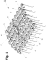
- a soil cultivation device 1 comprises a support frame 2 which has six bars 3 in the exemplary embodiment shown.
- the bars 3 are connected to one another via cheeks 4 arranged laterally in the support frame 2 .
- the bars 3 are rotatably mounted in the cheeks 4 in bearings 5, so that the bars 3 can be rotated about axes parallel to their longitudinal extensions.
- the harrow tines 10 made of spring steel have angled free ends 11, with the angled ends 11 engaging in the soil for soil tillage in order to remove weeds (cf. figure 5 ).
- the harrow tines 10 are attached to levers 12.
- the levers 12 are pivotably mounted on carriers 13, the carriers 13 being fastened to the bars 3 of the support frame 2.
- the levers 12 are pivotably mounted via bearings 15 on an arm 14 of the essentially two-armed carrier 13 .
- On the other arm 16 of the carrier 13 is a pneumatic cylinder 17, which acts as a pneumatic spring, supported in an articulated manner.
- the piston 19 of the pneumatic cylinder 17 is articulated to the lever 12 which carries the harrow tine 10 .
- the point at which the pneumatic cylinder 17 is connected to the lever 12 is at a distance from the pivot bearing 15 of the lever 13.
- the levers 12 have stop faces 18 which are arranged on the side of the lever 12 which is opposite the point at which the piston 19 of the pneumatic cylinder 17 engages the lever 12 and the end from which the harrow tine 10 protrudes.
- the stop surface 18 is in the in figure 5 shown active position of the harrow tine 10 on a side surface of the bar 3, on which the harrow tine 10 is pivotally mounted.
- the harrow tines 10 By applying pressure to the pneumatic cylinders 17, they act as a spring and the harrow tines 10 are prestressed into their active position, in which the stop surfaces 18 rest against the bars 3. Nevertheless, the harrow tines 10, especially if they encounter an obstacle, as is shown in 6 shown, pivot while compressing the pneumatic cylinder 17 and avoid the obstacle without damaging the harrow tines 10 .
- the pneumatic cylinders 17 are pressurized with compressed air via pressure control valves. It is thus possible to keep the tine pressure at the free ends 11 of the comb tines 10 the same in all pivot positions of the comb tines 10 . This does not only apply to those in the Figures 5 and 6 shown pivot positions of the harrow tines 10, but also for the entire pivot range between in the Figures 5 and 6 shown swivel positions of the harrow tines 10.
- an embodiment of the invention can be described as follows: In a soil tillage implement 1 with several harrow tines 10, the harrow tines 10 are fastened to levers 12, which are mounted pivotably on beams 13 on spars 3 of the support frame 2. The operative position of the harrow tines 10 is defined by the lever 12 resting against the spars 3 and the tines 10 are prestressed into the operative position by their associated springs in the form of pneumatic cylinders 17 .
Landscapes
- Life Sciences & Earth Sciences (AREA)
- Engineering & Computer Science (AREA)
- Mechanical Engineering (AREA)
- Soil Sciences (AREA)
- Environmental Sciences (AREA)
- Zoology (AREA)
- Soil Working Implements (AREA)
Description
- Derartige Geräte, die auch als Striegel bezeichnet werden, sind bekannt. Beispielsweise wird auf den im Prospekt "Hatzenbichler AUSTRIAN-AGRO-TECHNIK" gezeigten und beschriebenen "Original-Striegel" verwiesen. Dieser bekannte Striegel besitzt ein Traggestell mit mehreren Holmen, an denen Striegelzinken befestigt sind. Die Striegelzinken umfassen einen dreifach gewundenen Abschnitt, sodass die Zinken beim Bearbeiten des Bodens zum Entfernen von Unkraut aus Feldern mit Kulturpflanzen, wie Getreide, Soja, Mais, Sonnenblumen, Erdbeeren, Zuckerrüben, Raps und dgl., eingesetzt werden können.
- Ein weiteres gattungsgemäßes Bodenbearbeitungsgerät ist aus
EP 1 961 283 B1 bekannt. Dieses bekannte Bodenbearbeitungsgerät, das insbesondere zum Pflegen der Bodenflächen von Kulturpflanzungen bestimmt ist, besitzt ein Traggestell und mehrere, an dem Traggestell verschwenkbar angeordnete Striegelzinken. Weiters ist eine den Striegelzinken zugeordnete Verstelleinrichtung vorgesehen. - Mit Hilfe der Verstelleinrichtung kann die Vorspannung der über Federn vorgespannten Striegelzinken verstellt werden.
- Problematisch bei dem aus
EP 1 961 283 B1 bekannten Bodenbearbeitungsgerät ist es, dass die Striegelzinken über Schraubenfedern vorgespannt werden, was nicht nur ein erheblicher Aufwand, sondern auch störanfällig ist. - Aus
DE 199 56 953 A1 ,US 2019/0045700 A1 undDE 10 2016 107 951 A1 sind Bodenbearbeitungsgeräte mit federnden, den Boden furchend bearbeitenden Werkzeugen bekannt. - Aus
US 5,492,182 A ,US 6,164,386 A ,US 2012/0073844 A1 undWO 2018/191767 A1 sind gattungsgemäße Bodenbearbeitungsgeräte ("Striegel") bekannt. -
WO 2018/191767 A1 zeigt ein gattungsgemäßes Bodenbearbeitungsgerät mit schwenkbaren, in Lagern gelagerten Striegelzinken, wobei die über die Lager überstehenden Enden der Striegelzinken mit Druck-Schraubenfedern gekuppelt sind. Der inWO 2018/191767 A1 erwähnte Hydraulikzylinder dient nicht dazu, die Striegelzinken zu bewegen oder federnd zu belasten, sondern einen Rahmen gegenüber dem Grundgestell zu verstellen. - Nachteilig bei diesem bekannten Bodenbearbeitungsgerät ist es, dass sich die Kraft, mit der Schraubenfedern auf die Striegelzinken einwirken, mit der Schwenklage der Striegelzinken ändert.
- Der aus
DE 10 2016 107 951 A1 bekannte Grubber für furchende Bodenbearbeitung, besitzt Federzinken mit wenigstens einer Federwindung. Dabei soll die Vorspannung einstellbar sein. Hierzu schlägtDE 10 2016 107 951 A1 vor, ein Auflageelement (Absatz [0020], Fig. 2a - 2d) vorzusehen. Absatz [0021] vonDE 10 2016 107 951 A1 erwähnt - ohne genauere Angaben, wie das verwirklicht sein kann - die Vorspannung der Federelemente mit einem hydraulischen oder pneumatischen Aktor und/oder einem Feder- und/oder Dämpfungselement einzustellen. Auch bei der Ausführungsform des Grubbers vonDE 10 2016 107 951 A1 wird die Federwirkung durch die Federwindung des Federzinkens selbst bestimmt. Ein Ausschwenken des Federzinken mit Hilfe einer schwenkbaren Lagerung offenbartDE 10 2016 107 951 A1 nicht. - Der Erfindung liegt die Aufgabe zugrunde, ein Bodenbearbeitungsgerät der eingangs genannten Gattung zur Verfügung zu stellen, bei dem die Striegelzinken in ihre Wirkstellung vorgespannt sind und - bezogen auf die Arbeitsrichtung - keine Querbewegungen (Schwingungen) in erheblichem Ausmaß ausführen.
- Gelöst wird diese Aufgabe erfindungsgemäß mit einem Bodenbearbeitungsgerät, das die Merkmale von Anspruch 1 aufweist.
- Bevorzugte und vorteilhafte Ausgestaltungen des erfindungsgemäßen Bodenbearbeitungsgerätes sind Gegenstand der Unteransprüche.
- Bei der Erfindung ist vorgesehen, dass die die Striegelzinken in ihre Wirkstellung belastenden, vorspannenden Federn pneumatische Federn sind. Da die pneumatischen Federn über Druckregelventile mit Druckluft beaufschlagt werden, ist gewährleistet, dass die Kraft, mit der Striegelzinken belastet werden, in allen Schwenkstellungen der Striegelzinken gleich groß ist, also auch bei zunehmenden Schwenken der Striegelzinken nicht größer wird.
- Da bei dem erfindungsgemäßen Bodenbearbeitungsgerät die Wirkstellung der Striegelzinken durch einen am Traggestell angeordneten Anschlag bestimmt ist und weil jeder Striegelzinke eine pneumatische Feder zugeordnet ist, die die Striegelzinke in ihre Wirkstellung vorspannt, ergibt sich nicht nur eine für die Kulturpflanzen schonende Bearbeitung, mit dem Ziel, Unkraut zu entfernen, sondern es sind auch Querbewegungen (Bewegungen der Striegelzinken quer zur Arbeitsrichtung) vollständig oder wenigstens weitgehend vermieden. In einer praktischen Ausführungsform des erfindungsgemäßen Bodenbearbeitungsgerätes sind die Striegelzinken an Hebeln befestigt, die ihrerseits am Traggestell, insbesondere an Holmen des Traggestells, verschwenkbar gelagert sind.
- In einer Ausführungsform des erfindungsgemäßen Bodenbearbeitungsgerätes ist vorgesehen, dass die pneumatischen Federn einerseits an den Trägern, an welchen die Hebel mit den Zinken verschwenkbar gelagert sind, und anderseits an den Hebeln mit Abstand von den Schwenkachsen der Hebel angreifen.
- Bei dem erfindungsgemäßen Bodenbearbeitungsgerät kann vorgesehen sein, dass die Holme im Traggestell verdrehbar gelagert sind, sodass die Striegelzinken aus einer Arbeitsposition (= Wirkstellung) in eine Transportposition verschwenkt werden können, wobei die Striegelzinken in der Transportposition dem Traggestell angenähert sind.
- Weitere Einzelheiten und Merkmale der Erfindung ergeben sich aus der nachstehenden Beschreibung eines bevorzugten Ausführungsbeispiels des erfindungsgemäßen Bodenbearbeitungsgerätes anhand der Zeichnungen. Es zeigt:
- Fig. 1
- ein Bodenbearbeitungsgerät in Schrägansicht,
- Fig. 2
- eine Draufsicht auf das Bodenbearbeitungsgerät von
Fig. 1 , - Fig. 3
- eine Seitenansicht des Bodenbearbeitungsgerätes von
Fig. 1 , wobei die Striegelzinken in Wirkstellung sind, - Fig. 4
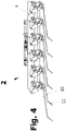
- das Bodenbearbeitungsgerät von
Fig. 1 mit in Transportposition verschwenkten Striegelzinken, - Fig. 5
- eine Einzelheit der Lagerung der Striegelzinken und der ihnen zugeordneten Feder,
- Fig. 6
- in einer Ansicht ähnlich
Fig. 5 die Lage der Striegelzinke, wenn diese auf ein Hindernis (Stein) aufläuft und - Fig. 7
- die von den Striegelzinken ausgeübten Zinkendrücke.
- Ein erfindungsgemäßes Bodenbearbeitungsgerät 1 umfasst ein Traggestell 2, das im gezeigten Ausführungsbeispiel sechs Holme 3 aufweist. Die Holme 3 sind über im Traggestell 2 seitlich angeordnete Wangen 4 miteinander verbunden. Dabei sind die Holme 3 in den Wangen 4 in Lagern 5 verdrehbar gelagert, sodass die Holme 3 um zu ihren Längserstreckungen parallele Achsen verdreht werden können.
- Zum Verdrehen der Holme 3 sind an ihnen Arme 6 befestigt, die miteinander über Kupplungsstangen 7 verbunden sind. Die Verbindungen der freien Enden der Arme 6 mit der Kupplungsstange 7 sind als Gelenke ausgebildet, sodass die Holme 3 durch Verstellen der Kupplungsstangen 7 mit Hilfe eines Hydraulikzylinders 8 verdreht werden können. So können die Striegelzinken 10 aus der in
Fig. 3 gezeigten Wirkstellung (= Arbeitsposition) in die inFig. 4 gezeigte Bereitschaftsstellung (= Transportposition) verschwenkt werden. - Die aus Federstahl bestehenden Striegelzinken 10 haben abgewinkelte freie Enden 11, wobei die abgewinkelten Enden 11 zur Bodenbearbeitung in den Boden eingreifen, um Unkraut zu entfernen (vgl.
Fig. 5 ). - Die Striegelzinken 10 sind an Hebeln 12 befestigt. Die Hebel 12 sind an Trägern 13 verschwenkbar gelagert, wobei die Träger 13 an den Holmen 3 des Traggestells 2 befestigt sind. An einem Arm 14 der im Wesentlichen zweiarmig ausgebildeten Träger 13 sind die Hebel 12 über Lager 15 verschwenkbar gelagert. An dem anderen Arm 16 der Träger 13 ist ein Pneumatikzylinder 17, der als pneumatische Feder wirkt, gelenkig abgestützt. Der Kolben 19 des Pneumatikzylinders 17 ist mit dem Hebel 12, welcher die Striegelzinke 10 trägt, gelenkig verbunden. Die Stelle, an welcher der Pneumatikzylinder 17 mit dem Hebel 12 verbunden ist, besitzt Abstand vom Schwenklager 15 der Hebel 13.
- Die Hebel 12 besitzen Anschlagflächen 18, die auf der Seite des Hebels 12 angeordnet sind, die der Stelle, an welcher der Kolben 19 des Pneumatikzylinders 17 am Hebel 12 angreift und dem Ende, von welchem die Striegelzinke 10 absteht, gegenüberliegt. Die Anschlagfläche 18 liegt in der in
Fig. 5 gezeigten Wirkstellung der Striegelzinke 10 an einer Seitenfläche des Holmes 3, an dem die Striegelzinke 10 schwenkbar gelagert ist, an. - Durch Beaufschlagen der Pneumatikzylinder 17 wirken diese als Feder und die Striegelzinken 10 werden in ihre Wirkstellung, in der die Anschlagflächen 18 an den Holmen 3 anliegen, vorgespannt. Trotzdem können die Striegelzinken 10, insbesondere wenn sie auf ein Hindernis stoßen, wie dies in
Fig. 6 gezeigt ist, unter Zusammendrücken des Pneumatikzylinders 17 verschwenken und dem Hindernis ausweichen, ohne dass die Striegelzinken 10 beschädigt werden. - Die Pneumatikzylinder 17 werden über Druckregelventile mit Druckluft beaufschlagt. So ist es möglich, den Zinkendruck an den freien Enden 11 der Striegelzinken 10 in allen Schwenklagen der Striegelzinken 10 gleich groß zu halten. Das gilt nicht nur für die in den
Fig. 5 und 6 gezeigten Schwenklagen der Striegelzinken 10, sondern auch für den ganzen Schwenkbereich zwischen den in denFig. 5 und 6 gezeigten Schwenklagen der Striegelzinken 10. - In
Fig. 7 ist der von Striegelzinken 10 in verschiedenen Schwenklagen ausgeübte Zinkendruck (F1 bis F6) dargestellt. Es gilt bei dem erfindungsgemäßen Bodenbearbeitungsgerät 1 F1=F2=F3=F4=F5=F6. - Zusammenfassend kann ein Ausführungsbeispiel der Erfindung wie folgt beschrieben werden:
Bei einem Bodenbearbeitungsgerät 1 mit mehreren Striegelzinken 10 sind die Striegelzinken 10 an Hebeln 12 befestigt, die über Träger 13 an Holmen 3 des Traggestells 2 verschwenkbar gelagert sind. Durch Anliegen der Hebel 12 an Holmen 3 ist die Wirkstellung der Striegelzinken 10 definiert und die Striegelzinken 10 werden durch ihnen zugeordnete Federn in Form von Pneumatikzylindern 17 in die Wirkstellung vorgespannt.
Claims (9)
- Bodenbearbeitungsgerät (1) mit einem Holme (3) umfassenden Traggestell (2), mit mehreren an dem Traggestell (2) verschwenkbar angeordneten Striegelzinken (10), wobei den Striegelzinken (10) je eine Feder zugeordnet ist, wobei die Wirkstellung der Striegelzinken (10) durch einen am Traggestell (2) angeordneten Anschlag bestimmt ist und wobei die Striegelzinken (10) durch die Federn in ihre Wirkstellung vorgespannt sind, dadurch gekennzeichnet, dass die Federn pneumatische Federn, insbesondere Pneumatikzylinder (17), sind und dass die pneumatischen Federn über Druckregelventile mit Druckluft beaufschlagt sind.
- Bodenbearbeitungsgerät nach Anspruch 1, dadurch gekennzeichnet, dass die Striegelzinken (10) an Hebeln (12) befestigt sind und dass die Hebel (12) am Traggestell (2) verschwenkbar gelagert sind.
- Bodenbearbeitungsgerät nach Anspruch 2, dadurch gekennzeichnet, dass die Hebel (12) über Träger (13) an Holmen (3) des Traggestells (2) verschwenkbar gelagert sind.
- Bodenbearbeitungsgerät nach Anspruch 2 oder 3, dadurch gekennzeichnet, dass die Hebel (12) voneinander unabhängig verschwenkbar sind.
- Bodenbearbeitungsgerät nach Anspruch 3 oder 4, dadurch gekennzeichnet, dass die Federn an den Trägern (13) abgestützt sind und an den Hebeln (12) mit Abstand von Lagern (15) der Hebel (12) an den Trägern (13) angreifen.
- Bodenbearbeitungsgerät nach einem der Ansprüche 3 bis 5, dadurch gekennzeichnet, dass in der Wirkstellung der Striegelzinken (10) ein Ende der Hebel (12) an dem als Anschlag dienenden Holm (3) des Traggestells (2), an dem auch der Träger (13) befestigt ist, anliegt.
- Bodenbearbeitungsgerät nach einem der Ansprüche 1 bis 6, dadurch gekennzeichnet, dass die Holme (3), an denen die Striegelzinken (10) angeordnet sind, im Traggestell (2) verdrehbar gelagert sind.
- Bodenbearbeitungsgerät nach Anspruch 7, dadurch gekennzeichnet, dass die Holme (3) in seitlichen Wangen (4) des Traggestells (2) verdrehbar gelagert sind.
- Bodenbearbeitungsgerät nach Anspruch 7 oder 8, dadurch gekennzeichnet, dass an den Holmen (3) Arme (6) befestigt sind, dass die freien Enden der Arme (6) miteinander über eine Kupplungsstange (7) verbunden sind und dass zum Betätigen der Kupplungsstange (7) ein Linearmotor, vorzugsweise ein Hydraulikzylinder (8), der im Traggestell (2) abgestützt ist, vorgesehen ist.
Applications Claiming Priority (1)
| Application Number | Priority Date | Filing Date | Title |
|---|---|---|---|
| ATA184/2019A AT521778B1 (de) | 2019-05-16 | 2019-05-16 | Bodenbearbeitungsgerät |
Publications (2)
| Publication Number | Publication Date |
|---|---|
| EP3738419A1 EP3738419A1 (de) | 2020-11-18 |
| EP3738419B1 true EP3738419B1 (de) | 2022-04-27 |
Family
ID=70553764
Family Applications (1)
| Application Number | Title | Priority Date | Filing Date |
|---|---|---|---|
| EP20172749.2A Active EP3738419B1 (de) | 2019-05-16 | 2020-05-04 | Bodenbearbeitungsgerät |
Country Status (4)
| Country | Link |
|---|---|
| US (1) | US11723297B2 (de) |
| EP (1) | EP3738419B1 (de) |
| AT (1) | AT521778B1 (de) |
| CA (1) | CA3080758C (de) |
Families Citing this family (7)
| Publication number | Priority date | Publication date | Assignee | Title |
|---|---|---|---|---|
| DE102020111400A1 (de) | 2020-04-27 | 2021-10-28 | Horsch Maschinen Gmbh | Bodenbearbeitungsmaschine, vorzugsweise landwirtschaftlicher hackstriegel und verfahren zum einstellen einer vorspannkraft an einem hackstriegel |
| DE202021103230U1 (de) * | 2021-06-16 | 2021-06-22 | Treffler Maschinenbau Gmbh & Co. Kg | Bodenbearbeitungsgerät |
| CN114158301A (zh) * | 2021-12-27 | 2022-03-11 | 蒙城县戴峰机械加工有限公司 | 一种弹尺机构及旋耕机 |
| DE102022114983A1 (de) | 2022-06-14 | 2023-12-14 | Lemken Gmbh & Co. Kg | Landwirtschaftliches Arbeitsgerät |
| CN114766155B (zh) * | 2022-06-20 | 2022-12-20 | 河北田康农业科技有限公司 | 一种桃形果树的种植装置及其方法 |
| EP4505852B1 (de) | 2023-08-11 | 2025-12-31 | Thomas Hatzenbichler Agro-Technik GmbH | Verfahren zum striegeln, striegelgerät und zugfahrzeug mit striegelgerät |
| DE102024113587A1 (de) * | 2024-05-15 | 2025-11-20 | Köckerling GmbH & Co. KG | Zinkenanordnung eines Bodenbearbeitungsgerätes und Bodenbearbeitungsgerät |
Citations (7)
| Publication number | Priority date | Publication date | Assignee | Title |
|---|---|---|---|---|
| US5988291A (en) | 1995-06-30 | 1999-11-23 | Yeomans; Allan J. | Soil penetrating tool assembly |
| DE19956953A1 (de) | 1998-12-18 | 2000-06-29 | Deere & Co | Gefederte Halterungsanordnung |
| US20160234994A1 (en) | 2015-02-10 | 2016-08-18 | Salford Group Inc. | Tine harrow |
| EP3097753A1 (de) | 2015-05-28 | 2016-11-30 | Hydac Technology Gmbh | Sicherungsvorrichtung |
| WO2016191825A1 (en) | 2015-06-05 | 2016-12-08 | The University Of Sydney | Automatic target recognition and management system |
| EP3245855A1 (de) | 2016-04-28 | 2017-11-22 | Horsch Maschinen GmbH | Landwirtschaftliches bodenbearbeitungsgerät, federzinken hierfür und anordnung eines federzinkens |
| WO2018191767A1 (de) | 2017-04-18 | 2018-10-25 | Schoels Juergen | Bodenbearbeitungsgerät |
Family Cites Families (17)
| Publication number | Priority date | Publication date | Assignee | Title |
|---|---|---|---|---|
| US2360022A (en) * | 1942-10-12 | 1944-10-10 | John S Troyer | Spike toothed harrow |
| US3016958A (en) * | 1958-06-30 | 1962-01-16 | Deere & Co | Harrows |
| US3043377A (en) * | 1959-11-18 | 1962-07-10 | Case Co J I | Spike tooth harrow |
| CA2119294C (en) * | 1994-03-17 | 1998-07-14 | Ronald T. Delaurier | Harrow |
| DE19839880A1 (de) * | 1998-09-02 | 2000-03-09 | Amazonen Werke Dreyer H | Strohstriegel |
| US6164386A (en) * | 1999-04-02 | 2000-12-26 | Delaurier; Ronald T. | Harrow |
| US7766093B2 (en) * | 2006-08-29 | 2010-08-03 | Deere & Company | Hydraulic lift rolling basket structure for a tillage implement |
| DE102007008616A1 (de) | 2007-02-22 | 2008-08-28 | Paul Treffler | Elektronische Zinkendruckverstelleinheit |
| US8657026B2 (en) * | 2010-09-29 | 2014-02-25 | Michael Ian James Friesen | Harrow |
| US10420271B2 (en) * | 2014-11-10 | 2019-09-24 | Cnh Industrial America Llc | Fully adjustable lift system |
| DE102015107648A1 (de) * | 2015-05-15 | 2016-11-17 | Horsch Maschinen Gmbh | Schnellwechselsystem eines Bodenbearbeitungswerkzeuges |
| US11266056B2 (en) * | 2015-10-23 | 2022-03-08 | Deere & Company | System and method for residue detection and implement control |
| CA2949080C (en) * | 2016-11-21 | 2018-11-13 | Bourgault Industries Ltd. | Biasing system for harrows |
| US10561056B2 (en) * | 2017-04-28 | 2020-02-18 | Cnh Industrial America Llc | System and method for monitoring soil conditions within a field |
| US11259454B2 (en) * | 2017-04-28 | 2022-03-01 | Cnh Industrial America Llc | System and method for detecting ground engaging tool float for an agricultural implement |
| US10375874B2 (en) * | 2017-08-10 | 2019-08-13 | Cnh Industrial America Llc | Dual rate sweep load on field cultivator shank assembly |
| CN110149814B (zh) * | 2019-04-24 | 2024-03-29 | 昆明理工大学 | 一种以砂鱼蜥为原型的仿生耐磨弹齿耙 |
-
2019
- 2019-05-16 AT ATA184/2019A patent/AT521778B1/de active
-
2020
- 2020-05-04 EP EP20172749.2A patent/EP3738419B1/de active Active
- 2020-05-14 CA CA3080758A patent/CA3080758C/en active Active
- 2020-05-14 US US15/931,912 patent/US11723297B2/en active Active
Patent Citations (7)
| Publication number | Priority date | Publication date | Assignee | Title |
|---|---|---|---|---|
| US5988291A (en) | 1995-06-30 | 1999-11-23 | Yeomans; Allan J. | Soil penetrating tool assembly |
| DE19956953A1 (de) | 1998-12-18 | 2000-06-29 | Deere & Co | Gefederte Halterungsanordnung |
| US20160234994A1 (en) | 2015-02-10 | 2016-08-18 | Salford Group Inc. | Tine harrow |
| EP3097753A1 (de) | 2015-05-28 | 2016-11-30 | Hydac Technology Gmbh | Sicherungsvorrichtung |
| WO2016191825A1 (en) | 2015-06-05 | 2016-12-08 | The University Of Sydney | Automatic target recognition and management system |
| EP3245855A1 (de) | 2016-04-28 | 2017-11-22 | Horsch Maschinen GmbH | Landwirtschaftliches bodenbearbeitungsgerät, federzinken hierfür und anordnung eines federzinkens |
| WO2018191767A1 (de) | 2017-04-18 | 2018-10-25 | Schoels Juergen | Bodenbearbeitungsgerät |
Non-Patent Citations (2)
| Title |
|---|
| DETER ALFONS: "Präzisionsgrubber Treffler TG 615", TOP AGRAR ONLINE, 17 August 2015 (2015-08-17), pages 1 - 5, XP093026133, Retrieved from the Internet <URL:https://www.topagrar.com/technik/news/praezisionsgrubber-treffler-tg-615-9359936.html> [retrieved on 20230222] |
| KÜPER JAN-MARTIN: "Fahrbericht - Präzise gegen Unkraut", LANDFREUND, 1 September 2014 (2014-09-01), pages 1 - 2, XP093026139, Retrieved from the Internet <URL:https://www.treffler.net/fileadmin/user_data/dokumente/news/treffler-praezisions-federzahnegge-praxisbericht-von-landfreund.pdf> [retrieved on 20230222] |
Also Published As
| Publication number | Publication date |
|---|---|
| EP3738419A1 (de) | 2020-11-18 |
| AT521778A4 (de) | 2020-07-15 |
| AT521778B1 (de) | 2020-07-15 |
| CA3080758A1 (en) | 2020-11-16 |
| CA3080758C (en) | 2025-12-16 |
| US11723297B2 (en) | 2023-08-15 |
| US20200359540A1 (en) | 2020-11-19 |
Similar Documents
| Publication | Publication Date | Title |
|---|---|---|
| AT521778B1 (de) | Bodenbearbeitungsgerät | |
| AT16450U2 (de) | Bodenbearbeitungsgerät | |
| DE2428917A1 (de) | Geraet, insbesondere bodenbearbeitungsgeraet | |
| DE2813295A1 (de) | Saatgut- und/oder duengerstreumaschine | |
| EP3612014B1 (de) | Bodenbearbeitungsgerät | |
| DE1152844B (de) | Steuervorrichtung fuer einen hydraulischen Kraftheber eines Ackerschleppers | |
| CH401565A (de) | Landwirtschaftliche Vorrichtung mit Bodenbearbeitungsgliedern | |
| EP4282238A1 (de) | Bodenbearbeitungsgerät | |
| EP4265086A1 (de) | Bodenbearbeitungsgerät | |
| DE2248186B2 (de) | ||
| DE2449648A1 (de) | Zugkraftfuehlvorrichtung fuer zugmaschinen | |
| EP4104654B1 (de) | Bodenbearbeitungsgerät mit hydraulischer überlastsicherung | |
| DE1482828B2 (de) | Radrechwender | |
| DE102015100273A1 (de) | Landwirtschaftliches Arbeitsgerät mit Zusatzfahrwerk | |
| DE2555890B2 (de) | Ueberlastsicherung der verbindung zwischen den pflugkoerpern und dem pflugrahmen eines ein- oder mehrscharigen volldrehpfluges | |
| DE102012110178A1 (de) | Landwirtschaftliches Arbeitsgerät | |
| DE3106660C2 (de) | Bodenbearbeitungsgerät im wesentlichen in Art einer Scheibenegge oder dergleichen | |
| EP3620038A1 (de) | Gezogener anbaugrubber | |
| DE1455578B2 (de) | Steuervorrichtung fuer ackerschlepper mit einem dreipunktgestaenge sowie einem hydraulischen kraftheber | |
| DE102021109467B4 (de) | Landwirtschaftliche Maschine und Verfahren zum Betreiben einer landwirtschaftlichen Maschine | |
| EP2628372A1 (de) | Einrichtung zur streifenweisen landwirtschaftlichen Bearbeitung von Böden | |
| EP2415336A1 (de) | Bodenbearbeitungsgerät | |
| EP3831176A1 (de) | Aufhängungsvorrichtung | |
| EP4505852B1 (de) | Verfahren zum striegeln, striegelgerät und zugfahrzeug mit striegelgerät | |
| EP1726199B1 (de) | Dreipunkt-Geräteanbau für einen zum Wein- und/oder Obstbau dienenden Traktor |
Legal Events
| Date | Code | Title | Description |
|---|---|---|---|
| PUAI | Public reference made under article 153(3) epc to a published international application that has entered the european phase |
Free format text: ORIGINAL CODE: 0009012 |
|
| STAA | Information on the status of an ep patent application or granted ep patent |
Free format text: STATUS: THE APPLICATION HAS BEEN PUBLISHED |
|
| AK | Designated contracting states |
Kind code of ref document: A1 Designated state(s): AL AT BE BG CH CY CZ DE DK EE ES FI FR GB GR HR HU IE IS IT LI LT LU LV MC MK MT NL NO PL PT RO RS SE SI SK SM TR |
|
| AX | Request for extension of the european patent |
Extension state: BA ME |
|
| STAA | Information on the status of an ep patent application or granted ep patent |
Free format text: STATUS: REQUEST FOR EXAMINATION WAS MADE |
|
| 17P | Request for examination filed |
Effective date: 20210303 |
|
| RBV | Designated contracting states (corrected) |
Designated state(s): AL AT BE BG CH CY CZ DE DK EE ES FI FR GB GR HR HU IE IS IT LI LT LU LV MC MK MT NL NO PL PT RO RS SE SI SK SM TR |
|
| RIC1 | Information provided on ipc code assigned before grant |
Ipc: A01B 61/04 20060101ALI20211029BHEP Ipc: A01B 35/24 20060101AFI20211029BHEP |
|
| GRAP | Despatch of communication of intention to grant a patent |
Free format text: ORIGINAL CODE: EPIDOSNIGR1 |
|
| STAA | Information on the status of an ep patent application or granted ep patent |
Free format text: STATUS: GRANT OF PATENT IS INTENDED |
|
| INTG | Intention to grant announced |
Effective date: 20211215 |
|
| GRAS | Grant fee paid |
Free format text: ORIGINAL CODE: EPIDOSNIGR3 |
|
| GRAA | (expected) grant |
Free format text: ORIGINAL CODE: 0009210 |
|
| STAA | Information on the status of an ep patent application or granted ep patent |
Free format text: STATUS: THE PATENT HAS BEEN GRANTED |
|
| AK | Designated contracting states |
Kind code of ref document: B1 Designated state(s): AL AT BE BG CH CY CZ DE DK EE ES FI FR GB GR HR HU IE IS IT LI LT LU LV MC MK MT NL NO PL PT RO RS SE SI SK SM TR |
|
| REG | Reference to a national code |
Ref country code: GB Ref legal event code: FG4D Free format text: NOT ENGLISH |
|
| REG | Reference to a national code |
Ref country code: CH Ref legal event code: EP |
|
| REG | Reference to a national code |
Ref country code: DE Ref legal event code: R096 Ref document number: 502020000995 Country of ref document: DE |
|
| REG | Reference to a national code |
Ref country code: AT Ref legal event code: REF Ref document number: 1486200 Country of ref document: AT Kind code of ref document: T Effective date: 20220515 |
|
| REG | Reference to a national code |
Ref country code: IE Ref legal event code: FG4D Free format text: LANGUAGE OF EP DOCUMENT: GERMAN |
|
| REG | Reference to a national code |
Ref country code: LT Ref legal event code: MG9D |
|
| REG | Reference to a national code |
Ref country code: NL Ref legal event code: MP Effective date: 20220427 |
|
| PG25 | Lapsed in a contracting state [announced via postgrant information from national office to epo] |
Ref country code: NL Free format text: LAPSE BECAUSE OF FAILURE TO SUBMIT A TRANSLATION OF THE DESCRIPTION OR TO PAY THE FEE WITHIN THE PRESCRIBED TIME-LIMIT Effective date: 20220427 |
|
| PG25 | Lapsed in a contracting state [announced via postgrant information from national office to epo] |
Ref country code: SE Free format text: LAPSE BECAUSE OF FAILURE TO SUBMIT A TRANSLATION OF THE DESCRIPTION OR TO PAY THE FEE WITHIN THE PRESCRIBED TIME-LIMIT Effective date: 20220427 Ref country code: PT Free format text: LAPSE BECAUSE OF FAILURE TO SUBMIT A TRANSLATION OF THE DESCRIPTION OR TO PAY THE FEE WITHIN THE PRESCRIBED TIME-LIMIT Effective date: 20220829 Ref country code: NO Free format text: LAPSE BECAUSE OF FAILURE TO SUBMIT A TRANSLATION OF THE DESCRIPTION OR TO PAY THE FEE WITHIN THE PRESCRIBED TIME-LIMIT Effective date: 20220727 Ref country code: LT Free format text: LAPSE BECAUSE OF FAILURE TO SUBMIT A TRANSLATION OF THE DESCRIPTION OR TO PAY THE FEE WITHIN THE PRESCRIBED TIME-LIMIT Effective date: 20220427 Ref country code: HR Free format text: LAPSE BECAUSE OF FAILURE TO SUBMIT A TRANSLATION OF THE DESCRIPTION OR TO PAY THE FEE WITHIN THE PRESCRIBED TIME-LIMIT Effective date: 20220427 Ref country code: GR Free format text: LAPSE BECAUSE OF FAILURE TO SUBMIT A TRANSLATION OF THE DESCRIPTION OR TO PAY THE FEE WITHIN THE PRESCRIBED TIME-LIMIT Effective date: 20220728 Ref country code: FI Free format text: LAPSE BECAUSE OF FAILURE TO SUBMIT A TRANSLATION OF THE DESCRIPTION OR TO PAY THE FEE WITHIN THE PRESCRIBED TIME-LIMIT Effective date: 20220427 Ref country code: BG Free format text: LAPSE BECAUSE OF FAILURE TO SUBMIT A TRANSLATION OF THE DESCRIPTION OR TO PAY THE FEE WITHIN THE PRESCRIBED TIME-LIMIT Effective date: 20220727 |
|
| PG25 | Lapsed in a contracting state [announced via postgrant information from national office to epo] |
Ref country code: RS Free format text: LAPSE BECAUSE OF FAILURE TO SUBMIT A TRANSLATION OF THE DESCRIPTION OR TO PAY THE FEE WITHIN THE PRESCRIBED TIME-LIMIT Effective date: 20220427 Ref country code: PL Free format text: LAPSE BECAUSE OF FAILURE TO SUBMIT A TRANSLATION OF THE DESCRIPTION OR TO PAY THE FEE WITHIN THE PRESCRIBED TIME-LIMIT Effective date: 20220427 Ref country code: LV Free format text: LAPSE BECAUSE OF FAILURE TO SUBMIT A TRANSLATION OF THE DESCRIPTION OR TO PAY THE FEE WITHIN THE PRESCRIBED TIME-LIMIT Effective date: 20220427 Ref country code: IS Free format text: LAPSE BECAUSE OF FAILURE TO SUBMIT A TRANSLATION OF THE DESCRIPTION OR TO PAY THE FEE WITHIN THE PRESCRIBED TIME-LIMIT Effective date: 20220827 |
|
| REG | Reference to a national code |
Ref country code: BE Ref legal event code: MM Effective date: 20220531 |
|
| REG | Reference to a national code |
Ref country code: DE Ref legal event code: R026 Ref document number: 502020000995 Country of ref document: DE |
|
| PG25 | Lapsed in a contracting state [announced via postgrant information from national office to epo] |
Ref country code: SM Free format text: LAPSE BECAUSE OF FAILURE TO SUBMIT A TRANSLATION OF THE DESCRIPTION OR TO PAY THE FEE WITHIN THE PRESCRIBED TIME-LIMIT Effective date: 20220427 Ref country code: SK Free format text: LAPSE BECAUSE OF FAILURE TO SUBMIT A TRANSLATION OF THE DESCRIPTION OR TO PAY THE FEE WITHIN THE PRESCRIBED TIME-LIMIT Effective date: 20220427 Ref country code: RO Free format text: LAPSE BECAUSE OF FAILURE TO SUBMIT A TRANSLATION OF THE DESCRIPTION OR TO PAY THE FEE WITHIN THE PRESCRIBED TIME-LIMIT Effective date: 20220427 Ref country code: MC Free format text: LAPSE BECAUSE OF FAILURE TO SUBMIT A TRANSLATION OF THE DESCRIPTION OR TO PAY THE FEE WITHIN THE PRESCRIBED TIME-LIMIT Effective date: 20220427 Ref country code: LU Free format text: LAPSE BECAUSE OF NON-PAYMENT OF DUE FEES Effective date: 20220504 Ref country code: ES Free format text: LAPSE BECAUSE OF FAILURE TO SUBMIT A TRANSLATION OF THE DESCRIPTION OR TO PAY THE FEE WITHIN THE PRESCRIBED TIME-LIMIT Effective date: 20220427 Ref country code: EE Free format text: LAPSE BECAUSE OF FAILURE TO SUBMIT A TRANSLATION OF THE DESCRIPTION OR TO PAY THE FEE WITHIN THE PRESCRIBED TIME-LIMIT Effective date: 20220427 Ref country code: DK Free format text: LAPSE BECAUSE OF FAILURE TO SUBMIT A TRANSLATION OF THE DESCRIPTION OR TO PAY THE FEE WITHIN THE PRESCRIBED TIME-LIMIT Effective date: 20220427 Ref country code: CZ Free format text: LAPSE BECAUSE OF FAILURE TO SUBMIT A TRANSLATION OF THE DESCRIPTION OR TO PAY THE FEE WITHIN THE PRESCRIBED TIME-LIMIT Effective date: 20220427 |
|
| PLBI | Opposition filed |
Free format text: ORIGINAL CODE: 0009260 |
|
| PLAX | Notice of opposition and request to file observation + time limit sent |
Free format text: ORIGINAL CODE: EPIDOSNOBS2 |
|
| 26 | Opposition filed |
Opponent name: LEMKEN GMBH & CO. KG Effective date: 20230127 |
|
| PG25 | Lapsed in a contracting state [announced via postgrant information from national office to epo] |
Ref country code: AL Free format text: LAPSE BECAUSE OF FAILURE TO SUBMIT A TRANSLATION OF THE DESCRIPTION OR TO PAY THE FEE WITHIN THE PRESCRIBED TIME-LIMIT Effective date: 20220427 |
|
| PG25 | Lapsed in a contracting state [announced via postgrant information from national office to epo] |
Ref country code: IE Free format text: LAPSE BECAUSE OF NON-PAYMENT OF DUE FEES Effective date: 20220504 |
|
| PG25 | Lapsed in a contracting state [announced via postgrant information from national office to epo] |
Ref country code: SI Free format text: LAPSE BECAUSE OF FAILURE TO SUBMIT A TRANSLATION OF THE DESCRIPTION OR TO PAY THE FEE WITHIN THE PRESCRIBED TIME-LIMIT Effective date: 20220427 Ref country code: BE Free format text: LAPSE BECAUSE OF NON-PAYMENT OF DUE FEES Effective date: 20220531 |
|
| PLBB | Reply of patent proprietor to notice(s) of opposition received |
Free format text: ORIGINAL CODE: EPIDOSNOBS3 |
|
| P01 | Opt-out of the competence of the unified patent court (upc) registered |
Effective date: 20230524 |
|
| REG | Reference to a national code |
Ref country code: CH Ref legal event code: PL |
|
| PG25 | Lapsed in a contracting state [announced via postgrant information from national office to epo] |
Ref country code: LI Free format text: LAPSE BECAUSE OF NON-PAYMENT OF DUE FEES Effective date: 20230531 Ref country code: CH Free format text: LAPSE BECAUSE OF NON-PAYMENT OF DUE FEES Effective date: 20230531 |
|
| PG25 | Lapsed in a contracting state [announced via postgrant information from national office to epo] |
Ref country code: MK Free format text: LAPSE BECAUSE OF FAILURE TO SUBMIT A TRANSLATION OF THE DESCRIPTION OR TO PAY THE FEE WITHIN THE PRESCRIBED TIME-LIMIT Effective date: 20220427 Ref country code: CY Free format text: LAPSE BECAUSE OF FAILURE TO SUBMIT A TRANSLATION OF THE DESCRIPTION OR TO PAY THE FEE WITHIN THE PRESCRIBED TIME-LIMIT Effective date: 20220427 |
|
| PG25 | Lapsed in a contracting state [announced via postgrant information from national office to epo] |
Ref country code: HU Free format text: LAPSE BECAUSE OF FAILURE TO SUBMIT A TRANSLATION OF THE DESCRIPTION OR TO PAY THE FEE WITHIN THE PRESCRIBED TIME-LIMIT; INVALID AB INITIO Effective date: 20200504 |
|
| PG25 | Lapsed in a contracting state [announced via postgrant information from national office to epo] |
Ref country code: TR Free format text: LAPSE BECAUSE OF FAILURE TO SUBMIT A TRANSLATION OF THE DESCRIPTION OR TO PAY THE FEE WITHIN THE PRESCRIBED TIME-LIMIT Effective date: 20220427 |
|
| PG25 | Lapsed in a contracting state [announced via postgrant information from national office to epo] |
Ref country code: MT Free format text: LAPSE BECAUSE OF FAILURE TO SUBMIT A TRANSLATION OF THE DESCRIPTION OR TO PAY THE FEE WITHIN THE PRESCRIBED TIME-LIMIT Effective date: 20220427 |
|
| REG | Reference to a national code |
Ref country code: DE Ref legal event code: R100 Ref document number: 502020000995 Country of ref document: DE |
|
| PG25 | Lapsed in a contracting state [announced via postgrant information from national office to epo] |
Ref country code: BG Free format text: LAPSE BECAUSE OF FAILURE TO SUBMIT A TRANSLATION OF THE DESCRIPTION OR TO PAY THE FEE WITHIN THE PRESCRIBED TIME-LIMIT Effective date: 20220427 |
|
| PG25 | Lapsed in a contracting state [announced via postgrant information from national office to epo] |
Ref country code: BG Free format text: LAPSE BECAUSE OF FAILURE TO SUBMIT A TRANSLATION OF THE DESCRIPTION OR TO PAY THE FEE WITHIN THE PRESCRIBED TIME-LIMIT Effective date: 20220427 |
|
| PLCK | Communication despatched that opposition was rejected |
Free format text: ORIGINAL CODE: EPIDOSNREJ1 |
|
| PLBN | Opposition rejected |
Free format text: ORIGINAL CODE: 0009273 |
|
| STAA | Information on the status of an ep patent application or granted ep patent |
Free format text: STATUS: OPPOSITION REJECTED |
|
| 27O | Opposition rejected |
Effective date: 20241024 |
|
| PGFP | Annual fee paid to national office [announced via postgrant information from national office to epo] |
Ref country code: DE Payment date: 20250516 Year of fee payment: 6 |
|
| PGFP | Annual fee paid to national office [announced via postgrant information from national office to epo] |
Ref country code: GB Payment date: 20250516 Year of fee payment: 6 |
|
| PGFP | Annual fee paid to national office [announced via postgrant information from national office to epo] |
Ref country code: IT Payment date: 20250528 Year of fee payment: 6 |
|
| PGFP | Annual fee paid to national office [announced via postgrant information from national office to epo] |
Ref country code: FR Payment date: 20250516 Year of fee payment: 6 |
|
| PGFP | Annual fee paid to national office [announced via postgrant information from national office to epo] |
Ref country code: AT Payment date: 20250527 Year of fee payment: 6 |