EP3736233B1 - Lastunterstützungssystem - Google Patents
Lastunterstützungssystem Download PDFInfo
- Publication number
- EP3736233B1 EP3736233B1 EP20173347.4A EP20173347A EP3736233B1 EP 3736233 B1 EP3736233 B1 EP 3736233B1 EP 20173347 A EP20173347 A EP 20173347A EP 3736233 B1 EP3736233 B1 EP 3736233B1
- Authority
- EP
- European Patent Office
- Prior art keywords
- conveyor
- popup
- article
- track
- guided vertical
- Prior art date
- Legal status (The legal status is an assumption and is not a legal conclusion. Google has not performed a legal analysis and makes no representation as to the accuracy of the status listed.)
- Active
Links
Images



Classifications
-
- B—PERFORMING OPERATIONS; TRANSPORTING
- B65—CONVEYING; PACKING; STORING; HANDLING THIN OR FILAMENTARY MATERIAL
- B65G—TRANSPORT OR STORAGE DEVICES, e.g. CONVEYORS FOR LOADING OR TIPPING, SHOP CONVEYOR SYSTEMS OR PNEUMATIC TUBE CONVEYORS
- B65G47/00—Article or material-handling devices associated with conveyors; Methods employing such devices
- B65G47/52—Devices for transferring articles or materials between conveyors i.e. discharging or feeding devices
-
- B—PERFORMING OPERATIONS; TRANSPORTING
- B65—CONVEYING; PACKING; STORING; HANDLING THIN OR FILAMENTARY MATERIAL
- B65G—TRANSPORT OR STORAGE DEVICES, e.g. CONVEYORS FOR LOADING OR TIPPING, SHOP CONVEYOR SYSTEMS OR PNEUMATIC TUBE CONVEYORS
- B65G47/00—Article or material-handling devices associated with conveyors; Methods employing such devices
- B65G47/74—Feeding, transfer, or discharging devices of particular kinds or types
- B65G47/88—Separating or stopping elements, e.g. fingers
- B65G47/8807—Separating or stopping elements, e.g. fingers with one stop
- B65G47/8815—Reciprocating stop, moving up or down in the path of the article
-
- B—PERFORMING OPERATIONS; TRANSPORTING
- B65—CONVEYING; PACKING; STORING; HANDLING THIN OR FILAMENTARY MATERIAL
- B65G—TRANSPORT OR STORAGE DEVICES, e.g. CONVEYORS FOR LOADING OR TIPPING, SHOP CONVEYOR SYSTEMS OR PNEUMATIC TUBE CONVEYORS
- B65G47/00—Article or material-handling devices associated with conveyors; Methods employing such devices
- B65G47/52—Devices for transferring articles or materials between conveyors i.e. discharging or feeding devices
- B65G47/64—Switching conveyors
- B65G47/641—Switching conveyors by a linear displacement of the switching conveyor
- B65G47/642—Switching conveyors by a linear displacement of the switching conveyor in a horizontal plane
-
- B—PERFORMING OPERATIONS; TRANSPORTING
- B65—CONVEYING; PACKING; STORING; HANDLING THIN OR FILAMENTARY MATERIAL
- B65G—TRANSPORT OR STORAGE DEVICES, e.g. CONVEYORS FOR LOADING OR TIPPING, SHOP CONVEYOR SYSTEMS OR PNEUMATIC TUBE CONVEYORS
- B65G13/00—Roller-ways
-
- B—PERFORMING OPERATIONS; TRANSPORTING
- B65—CONVEYING; PACKING; STORING; HANDLING THIN OR FILAMENTARY MATERIAL
- B65G—TRANSPORT OR STORAGE DEVICES, e.g. CONVEYORS FOR LOADING OR TIPPING, SHOP CONVEYOR SYSTEMS OR PNEUMATIC TUBE CONVEYORS
- B65G13/00—Roller-ways
- B65G13/02—Roller-ways having driven rollers
- B65G13/06—Roller driving means
-
- B—PERFORMING OPERATIONS; TRANSPORTING
- B65—CONVEYING; PACKING; STORING; HANDLING THIN OR FILAMENTARY MATERIAL
- B65G—TRANSPORT OR STORAGE DEVICES, e.g. CONVEYORS FOR LOADING OR TIPPING, SHOP CONVEYOR SYSTEMS OR PNEUMATIC TUBE CONVEYORS
- B65G43/00—Control devices, e.g. for safety, warning or fault-correcting
-
- B—PERFORMING OPERATIONS; TRANSPORTING
- B65—CONVEYING; PACKING; STORING; HANDLING THIN OR FILAMENTARY MATERIAL
- B65G—TRANSPORT OR STORAGE DEVICES, e.g. CONVEYORS FOR LOADING OR TIPPING, SHOP CONVEYOR SYSTEMS OR PNEUMATIC TUBE CONVEYORS
- B65G47/00—Article or material-handling devices associated with conveyors; Methods employing such devices
- B65G47/74—Feeding, transfer, or discharging devices of particular kinds or types
-
- B—PERFORMING OPERATIONS; TRANSPORTING
- B65—CONVEYING; PACKING; STORING; HANDLING THIN OR FILAMENTARY MATERIAL
- B65G—TRANSPORT OR STORAGE DEVICES, e.g. CONVEYORS FOR LOADING OR TIPPING, SHOP CONVEYOR SYSTEMS OR PNEUMATIC TUBE CONVEYORS
- B65G47/00—Article or material-handling devices associated with conveyors; Methods employing such devices
- B65G47/74—Feeding, transfer, or discharging devices of particular kinds or types
- B65G47/82—Rotary or reciprocating members for direct action on articles or materials, e.g. pushers, rakes, shovels
Definitions
- Example embodiments of the present invention relate generally to material handling systems, and more particularly, to load assist modules for transferring articles to a downstream system.
- material handling systems such as conveyors, vertical conveyors, and the like, are generally used to convey articles, such as, totes, containers, cartons, and the like, for further handling and/or processing.
- articles are regularly transferred from one material handling system to another throughout the processing cycle of the article.
- Applicant has identified several technical challenges associated with loading of the articles from one material handling system to a downstream system. Through applied effort, ingenuity, and innovation, many of these identified challenges have been overcome by developing solutions that are included in embodiments of the present invention, many examples of which are described in detail herein.
- JPH06115618A discloses a baggage passes over the horizontal rod of a pushing arm, the pushing arm is raised by an elevating device, and then, when a running body is moved from a retraction limit to an advancing limit by means of a running device, the pushing arm advances being left raised owing to the movement of the lower end of a vertical rod along a second guide rail and can push the baggage on a roller conveyor until it passes the front end of the roller conveyor.
- the pushing arm is retracted and lowered, retreating to a position where the carrying of the baggage on the roller conveyor is not obstructed.
- JPH06115618A discloses a load assist module according to the preamble of claim 1.
- JP2001341834A discloses when the container on the main carrying passage reaches a branch point to the sub carrying passage, a gate part is closed, the container is moved to a starting end of a stand by part, an engagement pin is abutted on and engaged with an inner circumference of a skirt part, and the container is pulled to a terminating end of the stand by part while correcting the position thereof.
- a pressing pin pushes the container, and transfers it to the starting end of the sub carrying passage onto a carrying base, a sliding mechanism is moved parallel to the loading position of the sub carrying passage, the container is left at the loading position by an unloading mechanism, and only the carrying base is returned to the starting end of the sub carrying passage.
- the illustrative embodiments of the present disclosure relate to systems and methods for loading articles in a material handling environment.
- a load assist module for transferring an article onto a downstream conveyor.
- the load assist module includes a roller conveyor having one or more rollers that together define a conveyor plane, such that the one or more rollers are actuatable to convey the article along the conveyor plane in a direction of a downstream conveyor.
- the load assist module further includes a pusher assembly that is positioned adjacent to the conveyor plane.
- the pusher assembly includes a track-guided vertical popup with a base and a pop-up, the pop-up may be actuatable such that the pop-up extends through the conveyor plane to contact the article. Further, the pusher assembly drives the track-guided vertical popup toward the direction of the downstream conveyor such that the track-guided vertical popup may push the article.
- the pusher assembly includes a drive assembly operatively coupled to the track-guided vertical popup.
- the drive assembly drives the track-guided vertical popup in a first direction, towards the downstream conveyor, to transfer the article onto the downstream conveyor, and drives the track-guided vertical popup in a second direction, away from the downstream conveyor, once the article is transferred onto the downstream conveyor.
- the drive assembly includes a timing belt driven by a pair of roller mounted timing pulleys. The timing belt is coupled to the track-guided vertical popup for driving the track-guided vertical popup in the first direction and the second direction.
- the drive assembly further includes a flag coupled to the timing belt such that the flag moves in a direction opposite to a direction of movement of the track-guided vertical popup.
- the drive assembly may include a pneumatic cylinder coupled to the track-guided vertical popup, such that the pneumatic cylinder may extend to drive the track-guided vertical popup in the first direction and may retract to drive the track-guided vertical popup in the second direction.
- the popup may be vertically movable to extend above the conveyor plane for pushing the article onto the downstream conveyor and retract below the conveyor plane for receiving a next article onto the load assist module.
- the load assist module further includes one or more pneumatic pop-out stops positioned adjacent to the downstream conveyor, such that the one or more pneumatic pop-out stops may extend to stop the article against the one or more pneumatic pop-out stops until the downstream conveyor may be ready to receive the article.
- the load assist module may further include a controller operatively coupled to the roller conveyor and the pusher assembly.
- the controller may receive a notification of a presence of the article on the roller conveyor.
- the controller may drive the roller conveyor to convey the article along the conveyor plane towards the downstream conveyor, actuate the pusher assembly to extend the track-guided vertical popup above the conveyor plane such that the track-guided vertical popup may contact the rear end of the article, and actuate the pusher assembly to drive the track-guided vertical popup against the rear end of the article to push the article onto the downstream conveyor.
- the load assist module may further include one or more guide rails positioned parallel to the conveyor plane for aligning and guiding the article while the article may be conveyed by the roller conveyor.
- a material handling system includes a conveyor for conveying an article in a conveyance direction, and a load assist module positioned adjacent the conveyor for receiving the article from the conveyor.
- the load assist module includes a roller conveyor having one or more rollers that together define a conveyor plane, such that the one or more rollers are actuatable to convey the article along the conveyor plane in a direction of a downstream conveyor.
- the load assist module further includes a pusher assembly that is positioned adjacent to the conveyor plane.
- the pusher assembly includes a track-guided vertical popup with a base and a pop-up, the pop-up is actuatable such that the pop-up extends through the conveyor plane to contact the article. Further, the pusher assembly drives the track-guided vertical popup toward the direction of the downstream conveyor such that the track-guided vertical popup may push the article.
- the downstream conveyor may include a vertical conveyor for moving the article vertically across one or more levels.
- the pusher assembly includes a drive assembly operatively coupled to the track-guided vertical popup.
- the drive assembly drives the track-guided vertical popup in a first direction, towards the downstream conveyor, to transfer the article onto the downstream conveyor, and drives the track-guided vertical popup in a second direction, away from the downstream conveyor, once the article is transferred onto the downstream conveyor.
- the drive assembly includes a timing belt driven by a pair of roller mounted timing pulleys. The timing belt is coupled to the track-guided vertical popup for driving the track-guided vertical popup in the first direction and the second direction.
- the drive assembly further includes a flag coupled to the timing belt such that the flag moves in a direction opposite to a direction of movement of the track-guided vertical popup.
- the drive assembly includes a pneumatic cylinder coupled to the track-guided vertical popup, such that the pneumatic cylinder extends to drive the track-guided vertical popup in the first direction and retracts to drive the track-guided vertical popup in the second direction.
- the popup is vertically movable to extend above the conveyor plane for pushing the article onto the downstream conveyor and retract below the conveyor plane for receiving a next article onto the load assist module.
- the material handling system further includes a controller operatively coupled to the load assist module.
- the controller receives a notification of a presence of the article on the roller conveyor.
- the controller drives the roller conveyor to convey the article along the conveyor plane towards the downstream conveyor, actuates the pusher assembly to extend the track-guided vertical popup above the conveyor plane such that the track-guided vertical popup contacts the rear end of the article, and actuates the pusher assembly to drive the track-guided vertical popup against the rear end of the article to push the article onto the downstream conveyor.
- a method of operating a load assist module for transferring an article onto a downstream conveyor may include receiving a notification of a presence of the article on a roller conveyor of the load assist module, in response to the notification, driving the roller conveyor to convey the article along a conveyor plane towards the downstream conveyor, actuating a pusher assembly, positioned adjacent the conveyor plane, having a track-guided vertical popup to extend the track-guided vertical popup above the conveyor plane such that the track-guided vertical popup contacts a rear end of the article, and actuating the pusher assembly to drive the track-guided vertical popup against the rear end of the article to push the article onto the downstream conveyor.
- the transfer and/or loading of the articles from one material handling system to a downstream material handling system may result in a loading error.
- a conveyor may load a tote onto a downstream conveyor, however, the tote may be partially loaded, may bounce back and/or be reoriented during the loading operation, resulting in a jam on the downstream conveyor.
- the downstream conveyor may also include a vertical conveyor.
- loading errors may introduce down time for the system and may require that an operator clears jams at high elevations which requires additional safety measures to resolve, further increasing down time of the system.
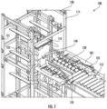
- the load assist module 105 includes a roller conveyor 125 for receiving the article 110 from the conveyor 113.
- the roller conveyor 125 may be coplanar with the conveyor 113 to receive the article 110.
- the roller conveyor 125 may convey the article 110 along a conveyor plane 130 in the direction of the downstream conveyor 115, as shown in FIG. 1 .
- the term conveyor plane 130 may be defined as a conveyance surface defined by a surface of the rollers and is bounded by one or more edges of the rollers of the roller conveyor 125.
- the support structure 122 may be coplanar with the roller conveyor 125 to support the article 110.
- roller conveyor 115 may include or may otherwise take the form of any other means for conveying an article, such as, belted conveyor, strip belts, and the like.
- the load assist module 105 includes a pusher assembly 135 positioned adjacent the conveyor plane 130 and along the roller conveyor 125 in the downstream direction, as shown in FIG. 1 .
- the pusher assembly 135 may be place in the center or substantially the center of the roller conveyer 125.
- the pusher assembly 135 includes a track-guided vertical popup 140 that extends vertically in the downstream direction and that may be extendable above the conveyor plane 130 and may be retractable below and/or in line with the conveyor plane 130. Further, the pusher assembly drives the track-guided vertical popup 140 horizontally towards the downstream conveyor 115.
- the track-guided vertical popup 140 is extendable above the conveyor plane 130 to contact the article 110, as shown in FIG. 1 . As shown in FIG. 1 , the track-guided vertical popup 140 is configured such that the track-guided vertical popup 140 pushes the article 110 onto the downstream conveyor 115 and loads the article 110 all the way into the vertical conveyor 120, thus, minimizing loading errors.
- FIG. 2 illustrates a perspective view of load assist module 105, in accordance with one or more example embodiments of the present disclosure.
- the roller conveyor 125 includes the article 110, having a frond end 205 and a rear end 210, and is shown resting on the surface of the one or more rollers (e.g., the conveyor plane 130).
- the load assist module 105 includes the pusher assembly 135 having the track-guided vertical popup 140 positioned adjacent the conveyor plane 130. As shown in FIG.
- the track-guided vertical popup 140 may be positioned in an initial position 202, that is, the track-guided vertical popup 140 may be fully retracted into the load assist module 105 such that the track-guided vertical popup 140 may be positioned adjacent the rear end 210 of the article 110. Further, as shown in FIG. 2 , the track-guided vertical popup 140 may extend vertically above the conveyor plane 130, by means of a pneumatic cylinder, for example, to contact the rear end 210 of the article 110 when the article 110 may be detected to be present on the roller conveyor 125 by one or more sensors of the load assist module 105.
- the pusher assembly 135 may drive the track-guided vertical popup 140 in a first direction 215 towards a downstream conveyor (not shown) for transferring the article 110 from the load assist module 105 onto the downstream conveyor. Further, in an example embodiment, the pusher assembly 135 drives the track-guided vertical popup 140 in a second direction 220 away from a downstream conveyor (not shown) to retract the track-guided vertical popup 140 into the load assist module 105, for example, after transferring the article 110 onto the downstream conveyor.
- the track-guided vertical popup 140 may be retracted vertically to be adjacent the conveyor plane 130 before, while, and/or after being retracted into the load assist module 105 to allow a next article to be conveyed on the roller conveyor 125 without impeding conveyance of the next article.
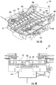
- FIG. 3A illustrates a perspective view of the load assist module 105, in accordance with one or more example embodiments of the present disclosure.
- the load assist module 105 includes the roller conveyor 125 for conveying an article (not shown) along the conveyor plane 130 towards a downstream conveyor (not shown).
- Adjacent to the first set of full length rollers 302 are two sets of short rollers 304 and 304'.
- the first set of short rollers 304 are bounded on a first side by the first wall 306 and a second side by wall 310 of the pusher assembly 135.
- the second set of short rollers 304' are bounded on a first side by the second wall 308 and a second side by wall 312 of the pusher assembly 135.
- one or more rollers in the first set of short rollers 304 may be aligned in parallel with one or more rollers in the second set of short rollers 304'.
- the first set of full length rollers 302 and the two sets of short rollers 304 and 304' may be arranged in series so as to form a conveying surface defining the conveyor plane 130 that is configured to convey an article.
- the load assist module 105 further includes the pusher assembly 135 having the track-guided vertical popup 140.
- the pusher assembly 135 is defined by opposing walls 310 and 312 that extend in a downstream direction from the first set of full length rollers 302 to a downstream end of the roller conveyor 125.
- each wall 310 and 312 comprises a track 305.
- the track 305 is defined by the walls 310 and 312 whereas in other examples the track 305 extends from or is attached to the walls 310 and 312.
- track 305 on each wall 310 and 315 may be arranged such that they extend in the same plane and oppose one another.
- track 305 may be sized to receive protrusions 335 and 335', as shown in FIG. 3C , that extends from track-guided vertical popup 140.
- the track-guided vertical popup 140 comprises an elongate base 330.
- the base 330 may include protrusions 335 and 335' extending from both sides of the base 330.
- the protrusions 335 and 335' may be sized to fit in the channel and/or tracks defined by the walls of the pusher assembly, as described above.
- Base 330 may further comprise a vertical pop-up 323 having a pop-up head 325 coupled to a pop-up base 327.
- the pop-up head 325 may be operatively coupled to a pneumatic cylinder such that the pop-up head 325 may be vertically movable relative to the base 330 and relative to a conveyor plane.
- the pop-up head 325 may be coupled to the pop-up base 327 through pistons 328 movable pneumatically in and out of openings 329 formed in the pop-up base 327.
- FIG. 3C illustrates the track-guided vertical popup 140 with the pop-head 325 extending from the pop-up base 327.
- FIG. 3D illustrates the track-guided vertical popup 140 with the pop-head 325 retracting into the pop-up base 327.
- the track-guided vertical popup 140 may be extendable to be positioned above the conveyor plane 130 and may be retractable relative to the to be positioned in line with and/or below the conveyor plane 130 for receiving a next article onto the load assist module 105.
- the load assist module 105 further includes opposing pneumatic pop-out stops 310 positioned at the downstream end of the load assist module 105 such that they are adjacent to a downstream conveyor, as shown in FIG. 3A .
- the pneumatic pop-out stops 310 may be coupled to one or more pneumatic cylinders, such that the pneumatic pop-out stops 310 may be extendable inwardly toward one another and, thus, may be configured to stop an article, until the downstream conveyor may be ready to receive the article.
- the pneumatic pop-out stops 310 may be retractable to allow the article at a front of the load assist module 105 to be transferred onto the downstream conveyor, when the downstream conveyor may be ready to receive the article.
- the load assist module 105 may further include guide rails 315 positioned parallel to the conveyor plane 130.
- Guide rails 315 may be attached to one or more supports that may extend in a perpendicular direction from the conveyor plane 130.
- the guide rails 315 may be positioned such that they extend along the length of the conveyor plane 130 and are parallel to the roller conveyor 125.
- the guide rails 315 may be parallel to one another for a portion of their length and may curve outwardly away from one another for another portion of their length.
- the guide rails 315 may align and guide an article being conveyed on the roller conveyor 125 to a desired position and/or orientation.
- the guide rails 315 may guide the article such that the article may be positioned above the pusher assembly 135.
- the load assist module 105 may further include one or more sensors 320 mounted at different locations on the load assist module 105 to track the movement of the article on the load assist module 105.
- the sensors 320 may include, but are not limited to, photoeyes, encoders, proximity sensors, and the like.
- one or more sensors 320 positioned at a rear end of the load assist module 105 may detect that the roller conveyor 125 may be clear and ready to receive an article from an upstream conveyor.
- the roller conveyor 125 may receive the article and convey the article along the conveyor plane 130 towards a downstream conveyor. While the article may be conveyed by the roller conveyor 125, the guide rails 315 may guide and align the article, such that the article may pass over the track-guided vertical popup 140 that may be in a retracted position.
- the one or more sensors 320 may detect a presence of the article on the roller conveyor 125, and may actuate the pneumatic pop-out stops 310, such that the article may stop against the pneumatic pop-out stops 310.
- the pneumatic pop-out stops 310 may retract, and the roller conveyor 125 may start conveying the article towards the downstream conveyor.
- the track-guided vertical popup 140 may extend above the conveyor plane 130 and may contact a rear end of the article.
- the pusher assembly 135 may drive the track-guided vertical popup 140 along the track 305 and against the rear end of the article, thus, pushing the article onto the downstream conveyor.
- the track-guided vertical popup 140 may be retracted and be driven back into the load assist module 105 by the pusher assembly 135.
- FIG. 3B illustrates a front view of the load assist module 105, in accordance with one or more example embodiments of the present disclosure.
- the track-guided vertical popup 140 may be retracted vertically, such that, the pop-up head 325 may be retracted into the pop-up base 327 and be in line with and/or below a top surface of the roller conveyor 125. That is, the pop-up head 325 may be adjacent the conveyor plane 130, so as to allow an article to be conveyed on the roller conveyor 125 without being impeded by the track-guided vertical popup 140.
- FIG. 4A illustrates a bottom view of the load assist module 105, in accordance with one or more example embodiments of the present disclosure.
- the pusher assembly 135 of the load assist module 105 includes a drive assembly 405 operatively coupled to the track-guided vertical popup (not shown) for driving the track-guided vertical popup, as described above.
- the drive assembly 405 includes a first roller mounted timing pulley 415 and a second roller mounted timing pulley 420, as shown in FIG. 4A .
- the first roller mounted timing pulley 415 may be mounted on a motorized roller and the second roller mounted timing pulley 420 may be mounted on an idler roller.
- the drive assembly 405 further includes a timing belt 410 reeved around and driven by the first roller mounted timing pulley 415 and the second roller mounted timing pulley 420.
- the timing belt 410 is coupled to the base 330 of the track-guided vertical popup 140 (not shown) of the pusher assembly 135, such that, as the timing belt 410 is driven by the first roller mounted timing pulley 415 and the second roller mounted timing pulley 420, the track-guided vertical popup 140 is driven along with the timing belt 410.
- the first roller mounted timing pulley 415 may be rotated in a first direction to drive the timing belt 410 forward, towards the downstream conveyor.
- the timing belt 410 may, in turn, drive the track-guided vertical popup 140 (not shown) that is coupled to the timing belt 410 towards the downstream conveyor.
- first roller mounted timing pulley 415 may be rotated in a second direction, opposite to the first direction, to drive the timing belt 410 backwards, away from the downstream conveyor, thus, moving the track-guided vertical popup 140 back into the load assist module 105.
- the drive assembly 405 includes a flag 425 coupled to the timing belt 410, as shown in FIG. 4A .
- the flag 425 is coupled to an underside of the timing belt 410, such that the flag 425 moves in a direction opposite to a direction of motion of the timing belt 410.
- the load assist module 105 includes one or more sensors, such as, but not limited to, proximity sensors, photoeyes, encoders, etc., that detect the flag 425 to determine a position of the timing belt 410.
- the flag 425 may move between sensors mounted on each end of the load assist module 105, such that, the sensors may detect a position of the flag 425.
- the load assist module 105 determines a position of the timing belt 410, and subsequently, a position of the track-guided vertical popup that are coupled to the timing belt 410.
- FIG. 4B illustrates a bottom view of the load assist module 105, in accordance with another example embodiment of the present disclosure.
- the drive assembly 405 may include a pneumatic cylinder 430 coupled to the track-guided vertical popup (not shown) of the pusher assembly 135.
- the pneumatic cylinder 430 may extend to drive the track-guided vertical popup towards the downstream conveyor and may retract to drive the track-guided vertical popup away from the downstream conveyor and back into the load assist module 105.
- FIG. 5 illustrates a schematic block diagram of a controller 500 for controlling the operation of the load assist module 105, in accordance with one or more embodiments of the present disclosure.
- the controller 500 may include at least one processor 520, memory 525, communication module 530, and input/output module 535.
- the processor 520 may be configured with processor executable instructions to perform operations described herein.
- Processor 520 may, for example, be embodied as various means including one or more microprocessors with accompanying digital signal processor(s), one or more processor(s) without an accompanying digital signal processor, one or more coprocessors, one or more multi-core processors, one or more controllers, processing circuitry, one or more computers, various other processing elements including integrated circuits such as, for example, an ASIC (application specific integrated circuit) or FPGA (field programmable gate array), or some combination thereof. Accordingly, although illustrated in FIG. 5 as a single processor, in some embodiments processor 520 may comprise a plurality of processors. The plurality of processors may be embodied on a single device or may be distributed across a plurality of devices.
- the plurality of processors may be in operative communication with each other and may be collectively configured to perform one or more functionalities of the controller 500 as described herein.
- processor 520 is configured to execute instructions stored in memory 525 or otherwise accessible to processor 520. These instructions, when executed by processor 520, may cause controller 500 to perform one or more of the functionalities of controller 500, as will be described with reference to FIG. 6 .
- Memory 525 may comprise, for example, volatile memory, non-volatile memory, or some combination thereof. Although illustrated in FIG. 5 as a single memory, memory 525 may comprise a plurality of memory components. The plurality of memory components may be embodied on a single device or distributed across a plurality of devices.
- memory 525 may comprise, for example, a hard disk, random access memory, cache memory, read only memory (ROM), erasable programmable read-only memory (EPROM) & electrically erasable programmable read-only memory (EEPROM), flash memory, magnetic cassettes, magnetic tape, magnetic disk storage or other magnetic storage devices, a compact disc read only memory (CD-ROM), digital versatile disc read only memory (DVD-ROM), an optical disc, circuitry configured to store information, or some combination thereof.
- Memory 525 may be configured to store information, data (including item data and/or profile data), applications, instructions, or the like for enabling controller 500 to carry out various functions in accordance with example embodiments of the present disclosure.
- memory 525 may buffer input data for processing by processor 520. Additionally or alternatively, in at least some embodiments, memory 525 may store program instructions for execution by processor 520. Memory 525 may store information in the form of static and/or dynamic information. This stored information may be stored and/or used by the controller 500 during the course of performing its functionalities.
- Communications module 530 may be embodied as any device or means embodied in circuitry, hardware, a computer program product comprising computer readable program instructions stored on a computer readable medium (e.g., memory 525) and executed by a processing device (e.g., processor 520), or a combination thereof that is configured to receive and/or transmit data from/to another device and/or network, such as, for example, sensors, roller conveyor 125, pusher assembly 135, drive assembly 405, and the like.
- communications module 530 (like other components discussed herein) may be at least partially embodied as or otherwise controlled by processor 520.
- communications module 530 may be in communication with processor 520, such as via a bus.
- Communications module 530 may include, for example, an antenna, a transmitter, a receiver, a transceiver, network interface card and/or supporting hardware and/or firmware/software for enabling communications with another device. Communications module 530 may be configured to receive and/or transmit any data that may be stored by memory 525 using any protocol that may be used for communications between devices. Communications module 530 may additionally or alternatively be in communication with the memory 525, input/output module 535 and/or any other component of the controller 500, such as via a bus.
- Input/output module 535 may be in communication with processor 520 to receive an indication of a user input and/or to provide an audible, visual, mechanical, or other output to a user.
- input/output module 535 may include support, for example, for a keyboard, a mouse, a joystick, a display, a touch screen display, a microphone, a speaker, a RFID reader, barcode reader, biometric scanner, and/or other input/output mechanisms.
- controller 500 is embodied as a server or database
- aspects of input/output module 535 may be reduced as compared to embodiments where the controller 500 is implemented as an end-user machine (e.g., remote worker device and/or employee device) or other type of device designed for complex user interactions. In some embodiments (like other components discussed herein), input/output module 535 may even be eliminated from the controller 500.
- the controller 500 is embodied as a server or database
- at least some aspects of input/output module 535 may be embodied on an apparatus used by a user that is in communication with the controller 500.
- Input/output module 535 may be in communication with the memory 525, communications module 530, and/or any other component(s), such as via a bus.
- One or more than one input/output module and/or other component can be included in the controller 500.
- embodiments of the present disclosure may be configured as methods, conveyors, material handling systems, warehouse management servers, personal computers, servers, mobile devices, backend network devices, and the like. Accordingly, embodiments may comprise various means formed entirely of hardware or any combination of software and hardware. Furthermore, embodiments may take the form of a computer program product on at least one non-transitory computer-readable storage medium having computer-readable program instructions (e.g., computer software) embodied in the storage medium. Any suitable computer-readable storage medium may be utilized including non-transitory hard disks, CD-ROMs, flash memory, optical storage devices, or magnetic storage devices.
- These computer program instructions may also be stored in a computer-readable storage device (e.g., memory 525) that can direct a computer or other programmable data processing apparatus to function in a particular manner, such that the instructions stored in the computer-readable storage device produce an article of manufacture including computer-readable instructions for implementing the function discussed herein.
- the computer program instructions may also be loaded onto a computer or other programmable data processing apparatus to cause a series of operational steps to be performed on the computer or other programmable apparatus to produce a computer-implemented process such that the instructions that execute on the computer or other programmable apparatus provide steps for implementing the functions discussed herein.
- blocks of the block diagrams and flowchart illustrations support combinations of means for performing the specified functions, combinations of steps for performing the specified functions and program instruction means for performing the specified functions. It will also be understood that each block of the circuit diagrams and process flowcharts, and combinations of blocks in the circuit diagrams and process flowcharts, can be implemented by special purpose hardware-based computer systems that perform the specified functions or steps, or combinations of special purpose hardware and computer instructions.
- FIG. 6 illustrates an example method 600 for operating the load assist module 105, in accordance with one or more embodiments of the present disclosure not part of the invention.
- the method 600 may include, at block 605, receiving, by the material handling system 100, the load assist module 105, and/or the controller 500, a notification of a presence of the article 110 on a roller conveyor 125 of the load assist module 105.
- the roller conveyor 125 may receive the article 110 from an upstream conveyor.
- one or more sensors 320 may detect a presence of the article 110 on the roller conveyor 125 and may provide a notification of the presence of the article 110 on the roller conveyor 125 to the material handling system 100, the load assist module 105, and/or the controller 500.
- the one or more sensors 320 may include photoeyes, proximity sensors, encoders, etc. for detecting a presence of the article 110 on the roller conveyor 125.
- the method 600 may further include driving, by the material handling system 100, the load assist module 105, and/or the controller 500, the roller conveyor 125 to convey the article 110 along a conveyor plane 130 towards the downstream conveyor, at block 610.
- the method 600 further includes actuating, by the material handling system 100, the load assist module 105, and/or the controller 500, a pusher assembly 135, positioned adjacent the conveyor plane 130, having a track-guided vertical popup 140 to extend the track-guided vertical popup 140 above the conveyor plane 130 such that the track-guided vertical popup 140 contacts a rear end of the article 110, at block 615, as described above with reference to FIG. 1 to 4B .
- the method 600 may further include actuating, by the material handling system 100, the load assist module 105, and/or the controller 500, the pusher assembly 135 to drive the track-guided vertical popup 140 against the rear end of the article 110 to push the article 110 onto the downstream conveyor, at block 620, as described above with reference to FIG. 1 and 2 .
- the material handling system 100 including the load assist module 105 may transfer and/or load articles onto the downstream conveyors efficiently, thereby reducing, in some examples, loading errors, such as, bounce back, incomplete loading, etc.
- references within the specification to "one embodiment,” “an embodiment,” “embodiments”, or “one or more embodiments” are intended to indicate that a particular feature, structure, or characteristic described in connection with the embodiment is included in at least one embodiment of the present disclosure.
- the appearance of such phrases in various places within the specification are not necessarily all referring to the same embodiment, nor are separate or alternative embodiments mutually exclusive of other embodiments.
- various features are described which may be exhibited by some embodiments and not by others.
- various requirements are described which may be requirements for some embodiments but not other embodiments.
Landscapes
- Engineering & Computer Science (AREA)
- Mechanical Engineering (AREA)
- Control Of Conveyors (AREA)
- Discharge Of Articles From Conveyors (AREA)
Claims (9)
- Ladeassistenzmodul (105) zum Transferieren eines Artikels (110) auf einen nachgelagerten Förderer (115), das Ladeassistenzmodul umfassend:einen Rollenförderer (125), umfassend eine oder mehrere Rollen, die eine Fördererebene (130) definieren, wobei die eine oder die mehreren Rollen dazu betätigbar sind, den Artikel entlang der Fördererebene in eine Richtung eines nachgelagerten Förderers zu befördern;eine benachbart zu der Fördererebene positionierte Schieberanordnung (135), wobei die Schieberanordnung eine spurgeführte vertikale Ausklappvorrichtung (140) umfasst, die eine Basis und eine Ausklappvorrichtung definiert,wobei die Ausklappvorrichtung dazu betätigbar ist, sich durch die Fördererebene auszufahren, um in Kontakt mit dem Artikel zu kommen,wobei die Schieberanordnung dazu konfiguriert ist, die spurgeführte vertikale Ausklappvorrichtung in die Richtung des nachgelagerten Förderers anzutreiben, sodass die spurgeführte vertikale Ausklappvorrichtung den Artikel schiebt;eine Antriebsanordnung (405), umfassend einen von einem Paar auf Rollen montierten Zahnscheiben angetriebenen Zahnriemen (410), wobei der Zahnriemen mit der spurgeführten vertikalen Ausklappvorrichtung dazu gekoppelt ist:die spurgeführte vertikale Ausklappvorrichtung in eine erste Richtung (215) in Richtung des nachgelagerten Förderers anzutreiben, um den Artikel auf den nachgelagerten Förderer zu transferieren; unddie spurgeführte vertikale Ausklappvorrichtung in eine zweite Richtung (220) weg von dem nachgelagerten Förderer anzutreiben, sobald der Artikel auf den nachgelagerten Förderer transferiert ist;gekennzeichnet dadurch, dassdie Antriebsanordnung ferner eine Markierung (425) umfasst, die mit dem Zahnriemen gekoppelt und dazu konfiguriert ist, sich in eine Richtung entgegengesetzt zu einer Bewegungsrichtung der spurgeführten vertikalen Ausklappvorrichtung zu bewegen;und dadurch, dass das Ladeassistenzmodul ferner Folgendes umfasst:einen oder mehrere Sensoren, die dazu konfiguriert sind, die Markierung zu erkennen, wobei das Ladeassistenzmodul auf Basis dieser Erkennung dazu konfiguriert ist, Folgendes zu bestimmen: eine Position des Zahnriemens und eine Position der spurgeführten vertikalen Ausklappvorrichtung;einen oder mehrere pneumatische Ausklappanschläge (310), die benachbart zu dem nachgelagerten Förderer positioniert sind, sodass der eine oder die mehreren pneumatischen Ausklappanschläge sich ausfahren, um den Artikel gegen den einen oder die mehreren pneumatischen Ausklappanschläge anzuschlagen, bis der nachgelagerte Förderer bereit ist, den Artikel aufzunehmen.
- Ladeassistenzmodul nach Anspruch 1, wobei die Antriebsanordnung einen pneumatischen Zylinder (430) umfasst, der mit der spurgeführten vertikalen Ausklappvorrichtung gekoppelt ist, wobei der pneumatische Zylinder dazu konfiguriert ist, sich auszufahren, um die spurgeführte vertikale Ausklappvorrichtung in die erste Richtung anzutreiben, und sich einzufahren, um die spurgeführte vertikale Ausklappvorrichtung in die zweite Richtung anzutreiben.
- Ladeassistenzmodul nach Anspruch 1 oder 2, wobei die spurgeführte vertikale Ausklappvorrichtung einen Ausklappkopf umfasst, der betriebsfähig mit der Basis gekoppelt ist, wobei der Ausklappkopf vertikal beweglich ist, um sich zum Schieben des Artikels auf den nachgelagerten Förderer über die Fördererebene auszufahren und sich zum Aufnehmen eines nächsten Artikels auf das Ladeassistenzmodul unter die Fördererebene einzuziehen.
- Ladeassistenzmodul nach einem der Ansprüche 1-3, ferner umfassend eine Steuerung (500), die betriebsfähig mit dem Rollenförderer und der Schieberanordnung gekoppelt ist, wobei die Steuerung dazu konfiguriert ist:eine Benachrichtigung über eine Anwesenheit des Artikels auf dem Rollenförderer zu empfangen;als Antwort auf die Benachrichtigung den Rollenförderer dazu anzutreiben, den Artikel entlang der Fördererebene in Richtung des nachgelagerten Förderers zu befördern;die Schieberanordnung dazu zu betätigen, die spurgeführte vertikale Ausklappvorrichtung über die Fördererebene auszufahren, sodass die spurgeführte vertikale Ausklappvorrichtung in Kontakt mit dem hinteren Ende (210) des Artikels kommt; unddie Schieberanordnung dazu zu betätigen, die spurgeführte vertikale Ausklappvorrichtung gegen das hintere Ende des Artikels anzutreiben, um den Artikel auf den nachgelagerten Förderer zu schieben.
- Ladeassistenzmodul nach einem der Ansprüche 1-4, ferner umfassend eine oder mehrere Führungsschienen (315), die parallel zu der Fördererebene positioniert sind, um den Artikel auszurichten und zu führen, während der Artikel von dem Rollenförderer befördert wird.
- Materialhandhabungssystem (100), umfassend:einen Förderer zum Befördern eines Artikels in eine Förderrichtung; undein benachbart zu dem Förderer positioniertes Ladeassistenzmodul (105) zum Aufnehmen des Artikels (110) von dem Förderer, das Ladeassistenzmodul umfassend:einen Rollenförderer (125), umfassend eine oder mehrere Rollen, die eine Fördererebene (130) definieren, wobei die eine oder die mehreren Rollen dazu betätigbar sind, die Artikel entlang der Fördererebene in einer Richtung eines nachgelagerten Förderers zu befördern; undeine benachbart zu der Fördererebene positionierte Schieberanordnung (135), wobei die Schieberanordnung eine spurgeführte vertikale Ausklappvorrichtung (140) umfasst, die eine Basis und eine Ausklappvorrichtung definiert,wobei die Ausklappvorrichtung dazu betätigbar ist, sich durch die Fördererebene auszufahren, um in Kontakt mit dem Artikel zu kommen,eine Antriebsanordnung (405), umfassend einen von einem Paar auf Rollen montierten Zahnscheiben angetriebenen Zahnriemen (410), wobei der Zahnriemen mit der spurgeführten vertikalen Ausklappvorrichtung dazu gekoppelt ist:die spurgeführte vertikale Ausklappvorrichtung in eine erste Richtung (215) in Richtung des nachgelagerten Förderers anzutreiben, um den Artikel auf den nachgelagerten Förderer zu transferieren; unddie spurgeführte vertikale Ausklappvorrichtung in eine zweite Richtung (220) weg von dem nachgelagerten Förderer anzutreiben, sobald der Artikel auf den nachgelagerten Förderer transferiert ist;wobei die Antriebsanordnung ferner eine Markierung (425) umfasst, die mit dem Zahnriemen gekoppelt und dazu konfiguriert ist, sich in eine Richtung entgegengesetzt zu einer Bewegungsrichtung der spurgeführten vertikalen Ausklappvorrichtung zu bewegen;und das Ladeassistenzmodul ferner Folgendes umfasst:einen oder mehrere Sensoren, die dazu konfiguriert sind, die Markierung zu erkennen, wobei das Ladeassistenzmodul auf Basis dieser Erkennung dazu konfiguriert ist, Folgendes zu bestimmen: eine Position des Zahnriemens und eine Position der spurgeführten vertikalen Ausklappvorrichtung;wobei die Schieberanordnung dazu konfiguriert ist, die spurgeführte vertikale Ausklappvorrichtung in die Richtung des nachgelagerten Förderers anzutreiben, sodass die spurgeführte vertikale Ausklappvorrichtung den Artikel schiebt; und gekennzeichnet dadurch, dass das Ladeassistenzmodul (105) ferner Folgendes umfasst:
einen oder mehrere pneumatische Ausklappanschläge (310), die benachbart zu dem nachgelagerten Förderer positioniert sind, sodass der eine oder die mehreren pneumatischen Ausklappanschläge sich ausfahren, um den Artikel gegen den einen oder die mehreren pneumatischen Ausklappanschläge anzuschlagen, bis der nachgelagerte Förderer bereit ist, den Artikel aufzunehmen. - Materialhandhabungssystem nach Anspruch 6, wobei die Antriebsanordnung ferner einen pneumatischen Zylinder (430) umfasst, der mit der spurgeführten vertikalen Ausklappvorrichtung gekoppelt ist, sodass der pneumatische Zylinder sich ausfährt, um die spurgeführte vertikale Ausklappvorrichtung in die erste Richtung anzutreiben, und sich einfährt, um die spurgeführte vertikale Ausklappvorrichtung in die zweite Richtung anzutreiben.
- Materialhandhabungssystem nach Anspruch 6 oder 7, wobei die Ausklappvorrichtung vertikal beweglich ist, um sich zum Schieben des Artikels auf den nachgelagerten Förderer über die Fördererebene auszufahren und sich zum Aufnehmen eines nächsten Artikels auf das Ladeassistenzmodul unter die Fördererebene einzufahren.
- Materialhandhabungssystem nach einem der Ansprüche 6-8, ferner umfassend eine Steuerung (500), die betriebsfähig mit dem Ladeassistenzmodul gekoppelt ist, wobei die Steuerung dazu konfiguriert ist:eine Benachrichtigung über eine Anwesenheit des Artikels auf dem Rollenförderer zu empfangen;als Antwort auf die Benachrichtigung den Rollenförderer dazu anzutreiben, den Artikel entlang der Fördererebene in Richtung des nachgelagerten Förderers zu befördern;die Schieberanordnung dazu zu betätigen, die spurgeführte vertikale Ausklappvorrichtung über die Fördererebene auszufahren, sodass die spurgeführte vertikale Ausklappvorrichtung in Kontakt mit dem hinteren Ende (210) des Artikels kommt; unddie Schieberanordnung dazu zu betätigen, die spurgeführte vertikale Ausklappvorrichtung gegen das hintere Ende des Artikels anzutreiben, um den Artikel auf den nachgelagerten Förderer zu schieben.
Applications Claiming Priority (1)
| Application Number | Priority Date | Filing Date | Title |
|---|---|---|---|
| US16/407,789 US10988326B2 (en) | 2019-05-09 | 2019-05-09 | Load assist system |
Publications (2)
| Publication Number | Publication Date |
|---|---|
| EP3736233A1 EP3736233A1 (de) | 2020-11-11 |
| EP3736233B1 true EP3736233B1 (de) | 2025-07-02 |
Family
ID=70613699
Family Applications (1)
| Application Number | Title | Priority Date | Filing Date |
|---|---|---|---|
| EP20173347.4A Active EP3736233B1 (de) | 2019-05-09 | 2020-05-06 | Lastunterstützungssystem |
Country Status (3)
| Country | Link |
|---|---|
| US (1) | US10988326B2 (de) |
| EP (1) | EP3736233B1 (de) |
| CN (1) | CN111908088A (de) |
Families Citing this family (5)
| Publication number | Priority date | Publication date | Assignee | Title |
|---|---|---|---|---|
| US10829313B2 (en) * | 2018-08-02 | 2020-11-10 | Intelligrated Headquarters, Llc | Goods to operator workstation |
| CN113401830B (zh) * | 2021-06-30 | 2022-08-19 | 中铁七局集团第五工程有限公司 | 一种地铁盾构施工用全自动管片下井输送系统 |
| CN116354029B (zh) * | 2023-04-04 | 2025-07-04 | 苏州赛腾精密电子股份有限公司 | 一种供料机构 |
| CN118107952B (zh) * | 2024-04-09 | 2024-12-20 | 唐山英莱科技有限公司 | 砌筑设备连续送砖系统 |
| CN118514229A (zh) * | 2024-06-27 | 2024-08-20 | 沈阳和研科技股份有限公司 | 一种中转下料机构 |
Citations (1)
| Publication number | Priority date | Publication date | Assignee | Title |
|---|---|---|---|---|
| CN207861384U (zh) * | 2017-12-18 | 2018-09-14 | 上汽通用五菱汽车股份有限公司 | 阻挡装置及辊道线 |
Family Cites Families (28)
| Publication number | Priority date | Publication date | Assignee | Title |
|---|---|---|---|---|
| US1631125A (en) * | 1923-12-17 | 1927-06-07 | Uline Ice Scoring Machine Comp | Reciprocating feeder |
| US1858619A (en) * | 1929-03-11 | 1932-05-17 | Delamere And Williams Ltd | Tray carrying conveyer |
| US2891659A (en) * | 1957-05-23 | 1959-06-23 | Hayes Inc C I | Conveyor system and retractable latch therefor |
| US3036692A (en) * | 1960-12-27 | 1962-05-29 | Sr Edward J Kiefer | Parts transfer mechanism |
| US3362519A (en) * | 1966-08-22 | 1968-01-09 | Baker Perkins Inc | Apparatus for transferring products between a conveying surface and a variable speed onveyor such as a bakery oven conveyor |
| US3794158A (en) * | 1972-02-24 | 1974-02-26 | W Greenwood | Accumulating conveyor system |
| US3993200A (en) * | 1975-12-24 | 1976-11-23 | Ide Allan R | Cargo transport system |
| US4364468A (en) * | 1981-03-06 | 1982-12-21 | United States Steel Corporation | Apparatus for co-ordinating indexing movement of a conveyor with pivoting of a kickout arm adjacent the delivery end thereof |
| US4465177A (en) * | 1982-02-18 | 1984-08-14 | Dorner Mfg. Corp. | Elevator for a conveying system |
| JP3182589B2 (ja) | 1992-10-06 | 2001-07-03 | 株式会社岡村製作所 | ローラコンベヤ用荷押出し装置 |
| JPH06171741A (ja) | 1992-12-09 | 1994-06-21 | Murata Mach Ltd | コンベア装置 |
| PT900169E (pt) * | 1997-03-03 | 2001-04-30 | Gilgen Fordersysteme Ag | Dispositivo de transporte destinado a canais de prateleira existentes em instalacoes de armazenamento equipadas com prateleiras |
| US6209706B1 (en) * | 1999-02-26 | 2001-04-03 | G. Robert Tod, Jr. | Article grouping and transferring system |
| JP3516440B2 (ja) | 2000-06-02 | 2004-04-05 | 明光産業株式会社 | ガス容器移載装置 |
| FR2814729B1 (fr) * | 2000-10-02 | 2003-01-10 | Cogema | Procede et dispositif pour reguler l'espacement et la vitesse d'objets cheminant de facon aleatoire |
| US7296674B2 (en) | 2002-08-01 | 2007-11-20 | Jolex Enterprises, Inc. | Conveyor system load transfer methods and apparatus |
| US20040238326A1 (en) * | 2002-10-08 | 2004-12-02 | Wayne Lichti | Method and apparatus for material handling and storage |
| JP3915923B2 (ja) * | 2003-11-28 | 2007-05-16 | ソニー株式会社 | ワークの搬送装置 |
| US7007790B2 (en) | 2004-05-06 | 2006-03-07 | Brannon James D | Loading platform with twin roller conveyors |
| US20070051585A1 (en) * | 2005-09-08 | 2007-03-08 | Scott Darius M | Apparatus and method for guiding and sorting packages and containers |
| EP1914033B1 (de) * | 2006-10-16 | 2011-04-20 | Soudronic AG | Fördervorrichtungen für Gegenstände mit verschiedenen Grössen ; Schweisseinrichtung mit einer solchen Fördervorrichtung ; Verfahren zum Schweissen von Dosenzargen mit verschiedenen Grössen |
| US8893873B1 (en) * | 2012-03-27 | 2014-11-25 | HE&M Inc. | Material handling feed table |
| JP6387575B2 (ja) | 2014-08-08 | 2018-09-12 | 伊東電機株式会社 | 幅寄せコンベア装置 |
| EP3286114B1 (de) | 2015-04-21 | 2025-12-17 | Opex Corporation | Verfahren und vorrichtung zum speichern oder abrufen von elementen |
| JP6780588B2 (ja) * | 2017-05-30 | 2020-11-04 | 株式会社ダイフク | 物品搬送装置及び物品搬送設備 |
| US10994947B2 (en) * | 2018-04-11 | 2021-05-04 | Bell And Howell, Llc | Overhead reverse divert systems and methods |
| US10829313B2 (en) * | 2018-08-02 | 2020-11-10 | Intelligrated Headquarters, Llc | Goods to operator workstation |
| US10618746B2 (en) * | 2018-09-13 | 2020-04-14 | Intelligrated Headquarters, Llc | Tote exchange module |
-
2019
- 2019-05-09 US US16/407,789 patent/US10988326B2/en active Active
-
2020
- 2020-04-24 CN CN202010331062.6A patent/CN111908088A/zh active Pending
- 2020-05-06 EP EP20173347.4A patent/EP3736233B1/de active Active
Patent Citations (1)
| Publication number | Priority date | Publication date | Assignee | Title |
|---|---|---|---|---|
| CN207861384U (zh) * | 2017-12-18 | 2018-09-14 | 上汽通用五菱汽车股份有限公司 | 阻挡装置及辊道线 |
Also Published As
| Publication number | Publication date |
|---|---|
| US10988326B2 (en) | 2021-04-27 |
| EP3736233A1 (de) | 2020-11-11 |
| US20200354158A1 (en) | 2020-11-12 |
| CN111908088A (zh) | 2020-11-10 |
Similar Documents
| Publication | Publication Date | Title |
|---|---|---|
| EP3736233B1 (de) | Lastunterstützungssystem | |
| TW213509B (de) | ||
| CN104925444B (zh) | 一种移动堆垛式自动立库 | |
| CN111573214B (zh) | 托盘传送机 | |
| NL2022698B1 (en) | A method of processing profiles in a profile processing assembly and a profile infeed assembly for transporting profiles towards a working machine | |
| KR20230146554A (ko) | 차량 손상을 감소시키기 위한 차량 트랙을 갖는 재료 취급 장치 | |
| KR20070011226A (ko) | 컨베이어 시스템 상의 화물을 추적하는 방법 및 장치 | |
| CN115196227A (zh) | 一种二次分拨机构及双向分拣方法 | |
| CN117509120B (zh) | 一种采用光电编码器反馈的高精度伺服定速物流输送系统 | |
| KR20150116653A (ko) | 이송 장치 | |
| CN207844349U (zh) | 一种传送转向系统 | |
| KR102316979B1 (ko) | 이송로봇용 도킹 가이드 장치 | |
| US4516900A (en) | De-palletizer | |
| JPWO2024143092A5 (de) | ||
| CN103728308B (zh) | 翻转装置、具有该翻转装置的检测设备及翻转方法 | |
| WO2010106659A1 (ja) | 昇降移載装置及び搬送処理システム | |
| CN110844431A (zh) | 一种插接装置 | |
| JP2893224B2 (ja) | リードフレーム搬送装置 | |
| US11939103B2 (en) | Label placement system | |
| CN111266319A (zh) | 供件设备、控制方法、分拣系统和装置 | |
| JPH02147520A (ja) | 移載方法及び移載装置 | |
| US20210002078A1 (en) | Systems and Methods for High Throughput Object Handling and Screening | |
| CN108455144A (zh) | 靠边输送装置及其控制方法 | |
| JP3927933B2 (ja) | 搬送物のセンタリング装置 | |
| CN208576994U (zh) | 一种双伸位堆垛机 |
Legal Events
| Date | Code | Title | Description |
|---|---|---|---|
| PUAI | Public reference made under article 153(3) epc to a published international application that has entered the european phase |
Free format text: ORIGINAL CODE: 0009012 |
|
| STAA | Information on the status of an ep patent application or granted ep patent |
Free format text: STATUS: REQUEST FOR EXAMINATION WAS MADE |
|
| 17P | Request for examination filed |
Effective date: 20200506 |
|
| AK | Designated contracting states |
Kind code of ref document: A1 Designated state(s): AL AT BE BG CH CY CZ DE DK EE ES FI FR GB GR HR HU IE IS IT LI LT LU LV MC MK MT NL NO PL PT RO RS SE SI SK SM TR |
|
| AX | Request for extension of the european patent |
Extension state: BA ME |
|
| STAA | Information on the status of an ep patent application or granted ep patent |
Free format text: STATUS: EXAMINATION IS IN PROGRESS |
|
| 17Q | First examination report despatched |
Effective date: 20230301 |
|
| GRAP | Despatch of communication of intention to grant a patent |
Free format text: ORIGINAL CODE: EPIDOSNIGR1 |
|
| STAA | Information on the status of an ep patent application or granted ep patent |
Free format text: STATUS: GRANT OF PATENT IS INTENDED |
|
| INTG | Intention to grant announced |
Effective date: 20241216 |
|
| GRAS | Grant fee paid |
Free format text: ORIGINAL CODE: EPIDOSNIGR3 |
|
| GRAA | (expected) grant |
Free format text: ORIGINAL CODE: 0009210 |
|
| STAA | Information on the status of an ep patent application or granted ep patent |
Free format text: STATUS: THE PATENT HAS BEEN GRANTED |
|
| AK | Designated contracting states |
Kind code of ref document: B1 Designated state(s): AL AT BE BG CH CY CZ DE DK EE ES FI FR GB GR HR HU IE IS IT LI LT LU LV MC MK MT NL NO PL PT RO RS SE SI SK SM TR |
|
| REG | Reference to a national code |
Ref country code: GB Ref legal event code: FG4D |
|
| REG | Reference to a national code |
Ref country code: CH Ref legal event code: EP |
|
| REG | Reference to a national code |
Ref country code: DE Ref legal event code: R081 Ref document number: 602020053647 Country of ref document: DE Owner name: EUROSORT INC., OWINGS MILLS, US Free format text: FORMER OWNER: INTELLIGRATED HEADQUARTERS LLC, MASON, OH, US Ref country code: DE Ref legal event code: R081 Ref document number: 602020053647 Country of ref document: DE Owner name: INTELLIGRATED HEADQUARTERS LLC, MASON, US Free format text: FORMER OWNER: INTELLIGRATED HEADQUARTERS LLC, MASON, OH, US |
|
| REG | Reference to a national code |
Ref country code: DE Ref legal event code: R096 Ref document number: 602020053647 Country of ref document: DE |
|
| REG | Reference to a national code |
Ref country code: IE Ref legal event code: FG4D |
|
| REG | Reference to a national code |
Ref country code: NL Ref legal event code: MP Effective date: 20250702 |
|
| PG25 | Lapsed in a contracting state [announced via postgrant information from national office to epo] |
Ref country code: PT Free format text: LAPSE BECAUSE OF FAILURE TO SUBMIT A TRANSLATION OF THE DESCRIPTION OR TO PAY THE FEE WITHIN THE PRESCRIBED TIME-LIMIT Effective date: 20251103 |
|
| PG25 | Lapsed in a contracting state [announced via postgrant information from national office to epo] |
Ref country code: NL Free format text: LAPSE BECAUSE OF FAILURE TO SUBMIT A TRANSLATION OF THE DESCRIPTION OR TO PAY THE FEE WITHIN THE PRESCRIBED TIME-LIMIT Effective date: 20250702 |
|
| REG | Reference to a national code |
Ref country code: AT Ref legal event code: MK05 Ref document number: 1809056 Country of ref document: AT Kind code of ref document: T Effective date: 20250702 |
|
| PG25 | Lapsed in a contracting state [announced via postgrant information from national office to epo] |
Ref country code: IS Free format text: LAPSE BECAUSE OF FAILURE TO SUBMIT A TRANSLATION OF THE DESCRIPTION OR TO PAY THE FEE WITHIN THE PRESCRIBED TIME-LIMIT Effective date: 20251102 |
|
| PG25 | Lapsed in a contracting state [announced via postgrant information from national office to epo] |
Ref country code: NO Free format text: LAPSE BECAUSE OF FAILURE TO SUBMIT A TRANSLATION OF THE DESCRIPTION OR TO PAY THE FEE WITHIN THE PRESCRIBED TIME-LIMIT Effective date: 20251002 |
|
| REG | Reference to a national code |
Ref country code: LT Ref legal event code: MG9D |
|
| PG25 | Lapsed in a contracting state [announced via postgrant information from national office to epo] |
Ref country code: AT Free format text: LAPSE BECAUSE OF FAILURE TO SUBMIT A TRANSLATION OF THE DESCRIPTION OR TO PAY THE FEE WITHIN THE PRESCRIBED TIME-LIMIT Effective date: 20250702 |
|
| PG25 | Lapsed in a contracting state [announced via postgrant information from national office to epo] |
Ref country code: FI Free format text: LAPSE BECAUSE OF FAILURE TO SUBMIT A TRANSLATION OF THE DESCRIPTION OR TO PAY THE FEE WITHIN THE PRESCRIBED TIME-LIMIT Effective date: 20250702 |
|
| PG25 | Lapsed in a contracting state [announced via postgrant information from national office to epo] |
Ref country code: HR Free format text: LAPSE BECAUSE OF FAILURE TO SUBMIT A TRANSLATION OF THE DESCRIPTION OR TO PAY THE FEE WITHIN THE PRESCRIBED TIME-LIMIT Effective date: 20250702 |
|
| PG25 | Lapsed in a contracting state [announced via postgrant information from national office to epo] |
Ref country code: GR Free format text: LAPSE BECAUSE OF FAILURE TO SUBMIT A TRANSLATION OF THE DESCRIPTION OR TO PAY THE FEE WITHIN THE PRESCRIBED TIME-LIMIT Effective date: 20251003 |
|
| PG25 | Lapsed in a contracting state [announced via postgrant information from national office to epo] |
Ref country code: CZ Free format text: LAPSE BECAUSE OF FAILURE TO SUBMIT A TRANSLATION OF THE DESCRIPTION OR TO PAY THE FEE WITHIN THE PRESCRIBED TIME-LIMIT Effective date: 20250702 Ref country code: SE Free format text: LAPSE BECAUSE OF FAILURE TO SUBMIT A TRANSLATION OF THE DESCRIPTION OR TO PAY THE FEE WITHIN THE PRESCRIBED TIME-LIMIT Effective date: 20250702 |
|
| PG25 | Lapsed in a contracting state [announced via postgrant information from national office to epo] |
Ref country code: LV Free format text: LAPSE BECAUSE OF FAILURE TO SUBMIT A TRANSLATION OF THE DESCRIPTION OR TO PAY THE FEE WITHIN THE PRESCRIBED TIME-LIMIT Effective date: 20250702 |
|
| PG25 | Lapsed in a contracting state [announced via postgrant information from national office to epo] |
Ref country code: BG Free format text: LAPSE BECAUSE OF FAILURE TO SUBMIT A TRANSLATION OF THE DESCRIPTION OR TO PAY THE FEE WITHIN THE PRESCRIBED TIME-LIMIT Effective date: 20250702 Ref country code: PL Free format text: LAPSE BECAUSE OF FAILURE TO SUBMIT A TRANSLATION OF THE DESCRIPTION OR TO PAY THE FEE WITHIN THE PRESCRIBED TIME-LIMIT Effective date: 20250702 |
|
| PG25 | Lapsed in a contracting state [announced via postgrant information from national office to epo] |
Ref country code: RS Free format text: LAPSE BECAUSE OF FAILURE TO SUBMIT A TRANSLATION OF THE DESCRIPTION OR TO PAY THE FEE WITHIN THE PRESCRIBED TIME-LIMIT Effective date: 20251002 |
|
| PG25 | Lapsed in a contracting state [announced via postgrant information from national office to epo] |
Ref country code: ES Free format text: LAPSE BECAUSE OF FAILURE TO SUBMIT A TRANSLATION OF THE DESCRIPTION OR TO PAY THE FEE WITHIN THE PRESCRIBED TIME-LIMIT Effective date: 20250702 |
|
| PG25 | Lapsed in a contracting state [announced via postgrant information from national office to epo] |
Ref country code: SM Free format text: LAPSE BECAUSE OF FAILURE TO SUBMIT A TRANSLATION OF THE DESCRIPTION OR TO PAY THE FEE WITHIN THE PRESCRIBED TIME-LIMIT Effective date: 20250702 |
|
| PG25 | Lapsed in a contracting state [announced via postgrant information from national office to epo] |
Ref country code: DK Free format text: LAPSE BECAUSE OF FAILURE TO SUBMIT A TRANSLATION OF THE DESCRIPTION OR TO PAY THE FEE WITHIN THE PRESCRIBED TIME-LIMIT Effective date: 20250702 |
|
| PG25 | Lapsed in a contracting state [announced via postgrant information from national office to epo] |
Ref country code: IT Free format text: LAPSE BECAUSE OF FAILURE TO SUBMIT A TRANSLATION OF THE DESCRIPTION OR TO PAY THE FEE WITHIN THE PRESCRIBED TIME-LIMIT Effective date: 20250702 |
|
| PG25 | Lapsed in a contracting state [announced via postgrant information from national office to epo] |
Ref country code: SK Free format text: LAPSE BECAUSE OF FAILURE TO SUBMIT A TRANSLATION OF THE DESCRIPTION OR TO PAY THE FEE WITHIN THE PRESCRIBED TIME-LIMIT Effective date: 20250702 Ref country code: EE Free format text: LAPSE BECAUSE OF FAILURE TO SUBMIT A TRANSLATION OF THE DESCRIPTION OR TO PAY THE FEE WITHIN THE PRESCRIBED TIME-LIMIT Effective date: 20250702 |