EP3736193A1 - Fahrzeug zur personenbeförderung mit einer klimatisierungsanordnung - Google Patents
Fahrzeug zur personenbeförderung mit einer klimatisierungsanordnung Download PDFInfo
- Publication number
- EP3736193A1 EP3736193A1 EP20167994.1A EP20167994A EP3736193A1 EP 3736193 A1 EP3736193 A1 EP 3736193A1 EP 20167994 A EP20167994 A EP 20167994A EP 3736193 A1 EP3736193 A1 EP 3736193A1
- Authority
- EP
- European Patent Office
- Prior art keywords
- air
- vehicle
- area
- openings
- duct
- Prior art date
- Legal status (The legal status is an assumption and is not a legal conclusion. Google has not performed a legal analysis and makes no representation as to the accuracy of the status listed.)
- Granted
Links
- 238000004378 air conditioning Methods 0.000 title claims abstract description 24
- 230000001143 conditioned effect Effects 0.000 claims abstract description 6
- 238000007664 blowing Methods 0.000 claims description 10
- 230000001154 acute effect Effects 0.000 claims description 3
- 238000007599 discharging Methods 0.000 claims description 2
- 230000007704 transition Effects 0.000 description 4
- 238000005253 cladding Methods 0.000 description 3
- 230000007423 decrease Effects 0.000 description 2
- 238000010438 heat treatment Methods 0.000 description 2
- 238000006243 chemical reaction Methods 0.000 description 1
- 238000001816 cooling Methods 0.000 description 1
- 230000000694 effects Effects 0.000 description 1
- 238000005516 engineering process Methods 0.000 description 1
- 239000012530 fluid Substances 0.000 description 1
- 238000004519 manufacturing process Methods 0.000 description 1
Images


Classifications
-
- B—PERFORMING OPERATIONS; TRANSPORTING
- B61—RAILWAYS
- B61D—BODY DETAILS OR KINDS OF RAILWAY VEHICLES
- B61D27/00—Heating, cooling, ventilating, or air-conditioning
- B61D27/0018—Air-conditioning means, i.e. combining at least two of the following ways of treating or supplying air, namely heating, cooling or ventilating
-
- B—PERFORMING OPERATIONS; TRANSPORTING
- B60—VEHICLES IN GENERAL
- B60H—ARRANGEMENTS OF HEATING, COOLING, VENTILATING OR OTHER AIR-TREATING DEVICES SPECIALLY ADAPTED FOR PASSENGER OR GOODS SPACES OF VEHICLES
- B60H1/00—Heating, cooling or ventilating [HVAC] devices
- B60H1/00357—Air-conditioning arrangements specially adapted for particular vehicles
- B60H1/00371—Air-conditioning arrangements specially adapted for particular vehicles for vehicles carrying large numbers of passengers, e.g. buses
-
- B—PERFORMING OPERATIONS; TRANSPORTING
- B60—VEHICLES IN GENERAL
- B60H—ARRANGEMENTS OF HEATING, COOLING, VENTILATING OR OTHER AIR-TREATING DEVICES SPECIALLY ADAPTED FOR PASSENGER OR GOODS SPACES OF VEHICLES
- B60H1/00—Heating, cooling or ventilating [HVAC] devices
- B60H1/00507—Details, e.g. mounting arrangements, desaeration devices
- B60H1/00557—Details of ducts or cables
- B60H1/00564—Details of ducts or cables of air ducts
-
- B—PERFORMING OPERATIONS; TRANSPORTING
- B60—VEHICLES IN GENERAL
- B60H—ARRANGEMENTS OF HEATING, COOLING, VENTILATING OR OTHER AIR-TREATING DEVICES SPECIALLY ADAPTED FOR PASSENGER OR GOODS SPACES OF VEHICLES
- B60H1/00—Heating, cooling or ventilating [HVAC] devices
- B60H1/24—Devices purely for ventilating or where the heating or cooling is irrelevant
- B60H1/241—Devices purely for ventilating or where the heating or cooling is irrelevant characterised by the location of ventilation devices in the vehicle
- B60H1/246—Devices purely for ventilating or where the heating or cooling is irrelevant characterised by the location of ventilation devices in the vehicle located in the interior of the vehicle or in or below the floor
Definitions
- the invention relates to a vehicle for passenger transport with an air-conditioning arrangement which has an air-conditioning device which is arranged in the roof area of the vehicle, a main air-conditioning duct to which conditioned air is applied by the air-conditioning device and which extends in the roof area in the longitudinal direction of the vehicle, and at least comprises an air duct branch starting from the main air-conditioning duct and running along side walls of the vehicle downwards towards the floor of a passenger compartment of the vehicle.
- Such vehicles can be, for example, rail vehicles or buses for transporting passengers.
- Modern rail vehicles in particular have to meet high demands on passenger comfort. These requirements are described, for example, for local transport in DIN-EN 14750.
- DIN-EN 14750 This results in certain values for temperature and air speed due to changing boundary conditions at different points in the passenger compartment.
- the air While in the case of cooling, the air is mainly blown from the ceiling, in which there are no interferences from interior equipment such as passenger seats, in the case of heating, the air is typically blown out in the passenger's footwell. In the case of heating, this means that the air outlet openings provided compete with the interior fittings of the passenger compartment for the available space in the lower part of the side wall.
- the invention is based on the object of further developing a vehicle of the type mentioned at the outset in such a way that the air-conditioning system is designed to be less complex and the cost of conversion measures to the air-conditioning system is reduced when the interior of the passenger compartment is changed.
- the vehicle described at the outset is characterized in that a lower end section of the air duct branch opens into a container-shaped air blow-out device which has several air blow-out openings which open directly into the passenger compartment of the vehicle.
- the floor ducts typically provided in the prior art are dispensed with, which extend in the longitudinal direction of the vehicle between two entry doors along the lower area of the side wall of the vehicle.
- the air blowout is independent of the seating landscape provided in the passenger compartment. If, for example, the interior fittings / the seating area in a passenger compartment is changed, it is sufficient to replace the initially provided air blower device with another air blower device that is similar in its external shape and whose air outlet openings are designed in such a way that the required values for temperature and air speed are met must be observed at various points in the passenger compartment.
- the air duct branch has a circular duct cross-section and the air duct blow-out device is cuboid.
- the circular duct cross-section of the air duct branch has the advantage that there are basically blow-out flows from the air blow-out device in all directions.
- the shape and size of the air outlet openings in individual surface areas of the air blow-out device can adapt the blow-out distribution of the air flow to the size and requirements of individual interior areas.
- the air blowing device can also have a round or semicircular horizontal cross section.
- the cuboid design specified above is characterized in that it is very easy to implement in terms of production technology.
- the respective design of the air blow-out device for different air blow-out environments can preferably be determined by means of CFD (computational fluid dynamics), in particular with regard to the alignment and dimensions of the individual air blow-out openings provided.
- CFD computational fluid dynamics
- the air exhaust device can preferably be arranged in the foot area of a door pillar trim of the vehicle, which is located in the longitudinal direction of the vehicle between an entry door to an entry area of the vehicle and a side wall which also laterally delimits a seat area of the vehicle to the outside.
- both the entry area of the vehicle and also suitable to supply the seating area with conditioned warm air it is possible both the entry area of the vehicle and also suitable to supply the seating area with conditioned warm air.
- both door pillar cladding of an entrance door will be equipped with such an air blowout device so that together they realize the appropriate air blowout for the entrance area.
- a seat area located between the two entrance doors in the longitudinal direction of the vehicle can also be suitably supplied with conditioned warm air.
- the air discharge openings of the air discharge device are advantageously dimensioned and arranged to realize a predominantly horizontal air discharge characteristic of the air discharge device.
- "predominantly horizontal” means that a velocity vector of the blown air is greater in the horizontal direction than in the vertical direction.
- the air discharge openings are preferably divided into several parts, each of which supplies other interior areas of the vehicle with air.
- a first part of the air outlet openings can be oriented for blowing out air along the side wall of the vehicle, so that the air is directed from a door pillar lining essentially along the side wall under the passenger seats close to the side wall.
- the first part of the air blow-out openings is located on that side wall of the air blow-out device which faces the seat area.
- a second part of the air outlet openings can be oriented into the seating area at an acute horizontal angle (for example 45 °) to the side wall for blowing out air.
- This second part of air discharge openings is located in the case of a cuboid design of the air discharge device on that outer wall of the air discharge device which faces a central aisle of the vehicle.
- On the same side can there is a third part of the air outlet openings, which is provided for blowing out air in the transverse direction of the vehicle.
- a fourth part of the air outlet openings can be aligned for blowing out air along the entrance door.
- these air blow-out openings are located on the side of the air blow-out device facing the entrance area.
- the air blow-out openings can be located directly in the flat outer walls of the air blow-out device, in particular if it is cuboid.
- the air blowout device has flow channel attachments for one or more of the parts of the air blowout openings described above for applying a predetermined flow direction to the discharging air, at the outlet end of which one of the air blowout openings is then arranged.
- the air outlet openings on each vertical side can be distributed over several gaps, for example, whereby a width of the air outlet openings can be constant, while - for example in the case of the first part of the air outlet openings - the air outlet openings in the area close to the floor can have a greater height than in the front Area further away from the ground.
- the air outlet openings are arranged and dimensioned in such a way that, for example, the first part of the air outlet openings offers a higher volume flow with a lower air speed in the seating area, whereby this can be adapted to the number of people in the seating area.
- the fourth part of the air outlet openings which allow air to be blown out into the entry area, can be designed in such a way that they can be compared results in less volume flow, but a higher speed of the air flow is made possible.
- the air flowing out of the fourth part of the air outlet openings can also be directed onto the floor of the entry area.
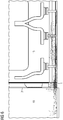
- a cuboid / cube-shaped air blower device 1 forms one of several outlet ends of an air-conditioning arrangement of a rail vehicle.
- this air conditioning arrangement typically comprises Air conditioning unit arranged in the roof area of the rail vehicle, which provides conditioned supply air for a passenger compartment of the rail vehicle.
- the air conditioning unit is connected to a main air conditioning duct, which extends in the longitudinal direction of the rail vehicle in the roof area.
- a plurality of air duct branches extend from this main air-conditioning duct, of which those for transporting warm air run essentially vertically along side walls of the rail vehicle, specifically in the direction of a floor 2 of a passenger compartment of the rail vehicle.
- an air duct branch 3 is shown by way of example, which has a circular duct cross-section and is connected to an upper side of the container-shaped air blower device 1.
- the direction of inflow is marked with an arrow 21.
- the warm air / supply air flowing in via the air duct branch 3 is distributed essentially uniformly in the container-shaped air blow-out device 1.
- the air blow-out device 1 is arranged directly in a foot area of a door pillar cladding 4.
- the side of the air blowout device 1 facing the door pillar arrangement 4 is closed.
- the three remaining vertical side walls 6, 8, 10 of the container-shaped air blow-out device 1 are each equipped with a plurality of air blow-out openings 5 which vary in their dimensions, alignment and arrangement.
- Only one air outlet opening 5 is designated with a reference symbol.
- the vertical side wall 6 of the air blower device 1 shown on the right is a seat area 7 (cf. Figures 2 and 3 ), a side wall 8 running in the longitudinal direction of the rail vehicle faces a central aisle 9, and another side wall 10 of the air blower device 1 faces an entry area 11.
- a first part 12 of the air outlet openings 5 is provided on the side wall 6.
- the air outlet openings 5 are arranged in two horizontally arranged columns next to one another, the lowest air outlet openings 5 being larger than the other air outlet openings 5 of the first part 12, which are designed as horizontal slits. This causes a high volume flow with low air speed to be achieved in the area close to the floor becomes. With increasing vertical distance from the floor 2, the air speed increases while the volume flow decreases. All of the air outlet openings 5 of the first part 12 are designed as simple openings in the side wall 6.
- the air blow-out openings 5 are each provided at the end of flow channel attachments 13, 14.
- the flow channel attachments 14 assigned to a second part 16 of the air discharge openings 5 present here in the form of horizontal slots are aligned such that air is blown out at an acute horizontal angle of approximately 45 ° to a side wall 15 of the rail vehicle.
- the second part 16 of the air discharge openings 5, which in turn are arranged vertically one above the other, thus ensure an oblique entry of the supply air into the seat area 7 of the rail vehicle.
- a third part 17 of the air discharge openings 5 is directed straight from the air discharge device 1 in the direction of the central aisle 9, the air discharge openings 5 of the third part 17 being arranged at the outlet ends of the flow channel attachments 13.
- the air outlet openings 5 of the third part 17 are also arranged vertically one above the other and are designed in the form of horizontal slots.
- a fourth part 18 of the air discharge openings 5 is provided on the side wall 10, the air discharge openings 5 present as simple breakthroughs.
- the air outlet openings 5 of the fourth part act on a floor area of the entry area 11 close to the door with supply air, the air outlet openings 5 being arranged in two vertical rows lying next to one another and designed as horizontal slots.
- Arrow patterns 19, 20 illustrate that the volume flow initially decreases from an area of the side wall 15 close to the floor in a horizontal plane over the seat area 7, the central aisle 9 towards the entry area 11, with an increase in the air speed. This has the effect that high air volume flows are introduced into the seat area 7. Only from a central section of the entry area 11 in the direction of a section of the entry area 11 close to the door does the air volume flow increase again, the air speed being reduced. In this case, the air volume flow in the entry area is basically also directed directly at the floor 2. In general, the air is discharged through all the air outlet openings 5 essentially horizontally.
- the Figures 4 , 5 and 6th illustrate calculation examples (CFD) for the air volume flows released by the air blower 1 go out. These show in more detail the spatial distribution / the air outlet pattern of the supply air flowing out from the air blower device 1 directly into the passenger compartment of the vehicle, as explained above.
Abstract
Description
- Die Erfindung bezieht sich auf ein Fahrzeug zur Personenbeförderung mit einer Klimatisierungsanordnung, die ein Klimagerät, das im Dachbereich des Fahrzeugs angeordnet ist, einen Hauptklimakanal, der von dem Klimagerät mit konditionierter Zuluft beaufschlagt wird und sich in dem Dachbereich in Längsrichtung des Fahrzeugs erstreckt, und wenigstens einen, von dem Hauptklimakanal ausgehenden, entlang von Seitenwänden des Fahrzeugs nach unten Richtung Fußboden eines Fahrgastinnenraumes des Fahrzeugs verlaufenden Luftkanalzweig umfasst.
- Bei solchen Fahrzeugen kann es sich beispielsweise um Schienenfahrzeuge oder um Busse zum Transport von Fahrgästen handeln. Insbesondere moderne Schienenfahrzeuge müssen hohe Anforderungen an einen Fahrgastkomfort erfüllen. Diese Anforderungen sind beispielsweise für den Nahverkehr in der DIN-EN 14750 beschrieben. Daraus ergeben sich aufgrund wechselnder Randbedingungen an verschiedenen Punkten im Fahrgastinnenraum bestimmte Werte für Temperatur und Luftgeschwindigkeit. Während im Kühlfall überwiegend von der Decke her ausgeblasen wird, bei der Störungen durch Inneneinrichtungen, wie Fahrgastsitze, nicht gegeben sind, wird im Heizfall typischerweise im Fußraum der Fahrgäste ausgeblasen. Dies bedeutet für den Heizfall, dass vorgesehene Luftausblasöffnungen mit der Inneneinrichtung des Fahrgastraums um den verfügbaren Platz im unteren Teil der Seitenwand konkurrieren. Auch besteht seitens Betreibern von Fahrzeugen zur Personenbeförderung häufig Bedarf, die Reiselandschaft (z. B. Bestuhlung) im Fahrgastinnenraum von Zeit zu Zeit zu verändern. Dies bringt es mit sich, dass vor allem die Position der Sitze flexibel gestaltet werden kann.
- Insbesondere bei Nahverkehrs-Schienenfahrzeugen, die nicht mittels Konvektionsheizern beheizt werden, sind für die Verteilung von Warmluft seitlich des Fahrgastinnenraumes in Bodennähe angebrachte Kanäle vorgesehen. Diese müssen jedoch wegen unterschiedlicher Sitzlandschaften und Befestigungsmöglichkeiten für jedes Fahrzeugprojekt separat eingestellt werden. Auch beanspruchen diese Kanäle Bauraum im unteren Bereich der Seitenwand der Fahrzeuge.
- Ausgehend hiervon liegt der Erfindung die Aufgabe zugrunde, ein Fahrzeug der eingangs genannten Art derart weiterzuentwickeln, dass die Klimatisierungsanordnung weniger komplex gestaltet ist und ein Aufwand an Umbaumaßnahmen an der Klimatisierungsanordnung bei einer Änderung der Inneneinrichtung des Fahrgastraumes vermindert wird.
- Diese Aufgabe wird gelöst durch ein Fahrzeug mit den Merkmalen des Anspruchs 1.
- Danach zeichnet sich das eingangs beschriebene Fahrzeug dadurch aus, dass ein unterer Endabschnitt des Luftkanalzweiges in eine behälterförmige Luftausblaseinrichtung mündet, die mehrere Luftausblasöffnungen aufweist, die unmittelbar in den Fahrgastinnenraum des Fahrzeugs münden.
- Bei dieser Art von Luftausblasung mittels der behälterförmigen Luftblaseinrichtung in den Fahrgastinnenraum des Fahrzeugs wird auf die im Stand der Technik typischerweise vorgesehenen Bodenkanäle verzichtet, die sich in Längsrichtung des Fahrzeugs zwischen zwei Einstiegstüren entlang des unteren Bereichs der Seitenwand des Fahrzeugs erstrecken. Dies bedeutet eine erhebliche Einsparung an Komponenten. Zudem ergibt sich eine Unabhängigkeit der Luftausblasung von einer vorgesehenen Sitzlandschaft im Fahrgastinnenraum. Wenn beispielsweise die Inneneinrichtungen / die Sitzlandschaft in einem Fahrgastinnenraum geändert werden, reicht es aus, die zunächst vorgesehene Luftausblaseinrichtung durch eine andere, in ihrer äußeren Form ähnliche Luftausblaseinrichtung zu ersetzen, deren Luftausblasöffnungen derart beschaffen sind, dass die erforderlichen Werte für Temperatur und Luftgeschwindigkeit an verschiedenen Punkten im Fahrgastinnenraum eingehalten werden. Alternativ ist es auch möglich, eine vorhandene Luftausblaseinrichtung hinsichtlich der Ausbildung und Anordnung ihrer Luftausblasöffnungen geeignet umzugestalten.
- Es ist bevorzugt, wenn der Luftkanalzweig einen kreisförmigen Kanalquerschnitt aufweist und die Luftkanalausblaseinrichtung quaderförmig ausgebildet ist. Der kreisförmige Kanalquerschnitt des Luftkanalzweigs hat den Vorteil, dass sich grundsätzlich Ausblasströmungen von der Luftausblaseinrichtung aus in alle Richtungen ergeben. Form und Größe der Luftauslassöffnungen in einzelnen Oberflächenbereichen der Luftausblaseinrichtung kann die Ausblasverteilung der Luftströmung an die Größe und Anforderungen einzelner Innenraumbereiche anpassen.
- In anderen Ausführungsvarianten kann die Luftausblaseinrichtung auch einen runden oder halbrunden Horizontal-Querschnitt aufweisen. Die oben angegebene quaderförmige Ausbildung zeichnet sich dadurch aus, dass sie fertigungstechnisch sehr einfach zu realisieren ist.
- Die jeweilige Auslegung der Luftausblaseinrichtung bei unterschiedlicher Luftausblasumgebung kann bevorzugt mittels CFD (computational fluid dynamics) bestimmt werden, insbesondere auch, was Ausrichtung und Abmessungen der einzelnen vorgesehenen Luftausblasöffnungen angeht.
- Die Luftausblaseinrichtung kann bevorzugt im Fußbereich einer Türsäulenverkleidung des Fahrzeugs angeordnet sein, die sich in Längsrichtung des Fahrzeugs zwischen einer Einstiegstür zu einem Einstiegsbereich des Fahrzeugs und einer Seitenwand befindet, die auch einen Sitzbereich des Fahrzeugs seitlich nach außen begrenzt.
- Bei einer solchen Positionierung der Luftausblaseinrichtung ist es möglich, sowohl den Einstiegsbereich des Fahrzeugs als auch den Sitzbereich geeignet mit konditionierter Warmluft zu versorgen. Typischerweise werden beide Türsäulenverkleidungen einer Einstiegstür mit einer solchen Luftausblaseinrichtung ausgestattet sein, so dass sie gemeinsam die geeignete Luftausblasung für den Einstiegsbereich realisieren. Wenn auch die nächste benachbarte Einstiegstür mit zwei solchen Luftausblaseinrichtungen ausgestattet ist, kann auch ein sich zwischen den beiden Einstiegstüren in Längsrichtung des Fahrzeugs befindlicher Sitzbereich geeignet mit konditionierter Warmluft beaufschlagt werden.
- Die Luftausblasöffnungen der Luftausblaseinrichtung sind vorteilhafterweise zum Realisieren einer überwiegend horizontalen Luftausblascharakteristik der Luftblaseinrichtung dimensioniert und angeordnet. Dabei heißt "überwiegend horizontal", dass ein Geschwindigkeitsvektor der ausgeblasenen Luft in horizontaler Richtung größer ist als in vertikaler Richtung.
- Bevorzugt sind die Luftausblasöffnungen in mehrere Teile unterteilt, die jeweils andere Innenraumbereiche des Fahrzeugs mit Luft versorgen. Ein erster Teil der Luftausblasöffnungen kann zum Ausblasen von Luft entlang der Seitenwand des Fahrzeugs ausgerichtet sein, so dass von einer Türsäulenverkleidung aus die Luft im Wesentlichen entlang der Seitenwand unter den seitenwandnahen Fahrgastsitzen hindurch gerichtet ist. Bei quaderförmiger Ausbildung der Luftausblaseinrichtung befindet sich der erste Teil der Luftausblasöffnungen an derjenigen Seitenwand der Luftausblaseinrichtung, die dem Sitzbereich zugewandt ist.
- Ein zweiter Teil der Luftausblasöffnungen kann zum Ausblasen von Luft in einem spitzen horizontalen Winkel (z. B. 45°) zur Seitenwand in den Sitzbereich hinein ausgerichtet sein. Dieser zweite Teil an Luftausblasöffnungen befindet sich bei quaderförmiger Ausbildung der Luftausblaseinrichtung an derjenigen Außenwand der Luftblaseinrichtung, die einem Mittelgang des Fahrzeugs zugewandt ist. An derselben Seite kann sich ein dritter Teil der Luftausblasöffnungen befinden, der zum Ausblasen von Luft in Querrichtung des Fahrzeugs vorgesehen ist.
- Ein vierter Teil der Luftausblasöffnungen kann zum Ausblasen von Luft entlang der Einstiegstür ausgerichtet sein. Bei quaderförmiger Ausbildung der Luftausblaseinrichtung befinden sich diese Luftausblasöffnungen an der dem Einstiegsbereich zugewandten Seite der Luftausblaseinrichtung.
- Grundsätzlich können sich die Luftausblasöffnungen unmittelbar in ebenen Außenwänden der Luftausblaseinrichtung befinden, insbesondere wenn sie quaderförmig ausgebildet ist. Zur besseren Ausrichtung der ausströmenden Luft kann vorgesehen sein, dass die Luftausblaseinrichtung für einen oder mehrere der oben beschriebenen Teile der Luftausblasöffnungen Strömungskanalansätze zum Beaufschlagen von ausströmender Luft mit einer vorbestimmten Strömungsrichtung aufweist, an deren Austrittsende dann jeweils eine der Luftausblasöffnungen angeordnet ist.
- Bei quaderförmiger Ausbildung der Luftausblaseinrichtung können die Luftausblasöffnungen an jeder Vertikalseite beispielsweise über mehrere Spalte verteilt sein, wobei eine Breite der Luftausblasöffnungen gleichbleibend sein kann, während - beispielsweise bei dem ersten Teil der Luftausblasöffnungen - die Luftauslassöffnungen im bodennahen Bereich eine größere Höhe aufweisen können als im vom Boden entfernteren Bereich.
- Es ist besonders günstig, wenn die Luftauslassöffnungen derart angeordnet und bemessen sind, dass beispielsweise der erste Teil der Luftausblasöffnungen einen höheren Volumenstrom mit geringerer Luftgeschwindigkeit im Sitzbereich bietet, wobei dies an eine im Sitzbereich vorhandene Personenzahl angepasst sein kann. Demgegenüber kann der vierte Teil der Luftausblasöffnungen, die eine Luftausblasung in den Einstiegsbereich gestatten, so gestaltet sein, dass sich vergleichsweise weniger Volumenstrom ergibt, jedoch eine höhere Geschwindigkeit der Luftströmung ermöglicht wird. Insbesondere kann die aus dem vierten Teil der Luftausblasöffnungen ausströmende Luft auch auf den Fußboden des Einstiegsbereichs gerichtet sein.
- Ein Ausführungsbeispiel der Erfindung wird nachfolgend unter Bezugnahme auf die Zeichnungen noch näher erläutert, wobei funktionsgleiche / -ähnliche Komponenten mit denselben Bezugszeichen bezeichnet sind. Es zeigen:
- Figur 1
- eine perspektivische Ansicht auf eine Luftausblaseinrichtung, angeordnet im Fußbereich einer Türsäulenverkleidung eines Schienenfahrzeugs,
- Figur 2
- eine schematische Ansicht von oben auf einen Fußbodenbereich des Schienenfahrzeugs von
Figur 1 , - Figur 3
- eine schematische Ansicht von oben eines Abschnitts des Fußbodenbereichs von
Figur 2 , - Figur 4
- eine perspektivische Ansicht eines Übergangsbereichs zwischen einem Einstiegsbereich und einem Sitzbereich des Schienenfahrzeugs von
Figur 1 , - Figur 5
- eine Ansicht von oben des Übergangsbereichs zwischen dem Einstiegsbereich und dem Sitzbereich von
Figur 4 und - Figur 6
- eine Seitenansicht des Übergangsbereichs zwischen Einstiegsbereich und Sitzbereich von
Figur 4 . - Wie aus
Figur 1 hervorgeht, bildet im dargestellten Ausführungsbeispiel eine quaderförmige/würfelförmige Luftausblaseinrichtung 1 eines von mehreren Austrittsenden einer Klimatisierungsanordnung eines Schienenfahrzeugs. In herkömmlicher Weise umfasst diese Klimatisierungsanordnung ein typischerweise im Dachbereich des Schienenfahrzeugs angeordnetes Klimagerät, welches konditionierte Zuluft für einen Fahrgastinnenraum des Schienenfahrzeugs bereitstellt. Das Klimagerät ist an einen Hauptklimakanal angeschlossen, welcher sich in Längsrichtung des Schienenfahrzeugs im Dachbereich erstreckt. Von diesem Hauptklimakanal gehen eine Mehrzahl von Luftkanalzweigen aus, von denen diejenigen zum Transport von Warmluft im Wesentlichen vertikal entlang von Seitenwänden des Schienenfahrzeugs verlaufen, und zwar Richtung eines Fußboden 2 eines Fahrgastinnenraums des Schienenfahrzeugs. - In
Figur 1 ist beispielhaft ein Luftkanalzweig 3 dargestellt, der einen kreisrunden Kanalquerschnitt aufweist und an eine Oberseite der behälterförmigen Luftausblaseinrichtung 1 angeschlossen ist. Dabei ist inFigur 1 die Einströmrichtung mit einem Pfeil 21 gekennzeichnet. - Die über den Luftkanalzweig 3 einströmende Warmluft / Zuluft verteilt sich im Wesentlichen gleichmäßig in der behälterförmigen Luftausblaseinrichtung 1. Die Luftausblaseinrichtung 1 ist unmittelbar in einem Fußbereich einer Türsäulenverkleidung 4 angeordnet. Die der Türsäulenanordnung 4 zugewandte Seite der Luftausblaseinrichtung 1 ist verschlossen. Die drei verbleibenden vertikalen Seitenwände 6, 8, 10 der behälterförmigen Luftausblaseinrichtung 1 sind jeweils mit einer Mehrzahl von Luftausblasöffnungen 5 ausgestattet, die in ihrer Dimensionierung, Ausrichtung und Anordnung variieren. Aus Gründen der Übersichtlichkeit ist in
Figur 1 auf der jeweiligen vertikalen Seitenwände 6, 8, 10 der Luftausblaseinrichtung 1 nur jeweils eine Luftaustrittsöffnung 5 mit einem Bezugszeichen bezeichnet. - Die in
Figur 1 rechts dargestellte vertikale Seitenwand 6 der Luftausblaseinrichtung 1 ist einem Sitzbereich 7 (vgl.Figuren 2 und3 ), eine in Längsrichtung des Schienenfahrzeugs verlaufende Seitenwand 8 ist einem Mittelgang 9 und eine weitere Seitenwand 10 der Luftausblaseinrichtung 1 ist einem Einstiegsbereich 11 zugewandt. - Ein erster Teil 12 der Luftaustrittsöffnungen 5 ist an der Seitenwand 6 vorgesehen. Im dargestellten Ausführungsbeispiel sind die Luftaustrittsöffnungen 5 in zwei horizontal nebeneinander angeordneten Spalten angeordnet, wobei unterste Luftaustrittsöffnungen 5 größer dimensioniert sind als die weiteren als horizontale Schlitze ausgebildeten Luftaustrittsöffnungen 5 des ersten Teils 12. Dies bewirkt, dass im bodennahen Bereich ein hoher Volumenstrom mit geringer Luftgeschwindigkeit realisiert wird. Mit zunehmendem vertikalen Abstand vom Boden 2 aus steigt die Luftgeschwindigkeit an, während der Volumenstrom abnimmt. Sämtliche Luftaustrittsöffnungen 5 des ersten Teils 12 sind als einfache Durchbrüche der Seitenwand 6 ausgebildet.
- Bei der dem Mittelgang 9 zugewandten Seitenwand 8 der Luftausblaseinrichtung 1 sind die Luftausblasöffnungen 5 jeweils am Ende von Strömungskanalansätzen 13, 14 vorgesehen. Dabei sind die einem zweiten Teil 16 der hier in Form von horizontalen Schlitzen vorliegenden Luftausblasöffnungen 5 zugeordneten Strömungskanalansätze 14 derart ausgerichtet, dass Luft in einem spitzen horizontalen Winkel von ca. 45° zu einer Seitenwand 15 des Schienenfahrzeugs ausgeblasen wird. Der zweite Teil 16 der Luftausblasöffnungen 5, die wiederum vertikal übereinander angeordnet sind, sorgen somit für einen schrägen Eintritt der Zuluft in den Sitzbereich 7 des Schienenfahrzeugs.
- Ein dritter Teil 17 der Luftausblasöffnungen 5 ist von der Luftausblaseinrichtung 1 aus gerade in Richtung auf den Mittelgang 9 gerichtet, wobei die Luftausblasöffnungen 5 des dritten Teils 17 jeweils an den Austrittsenden der Strömungskanalansätze 13 angeordnet sind. Auch die Luftausblasöffnungen 5 des dritten Teils 17 sind vertikal übereinander angeordnet und in Form horizontaler Schlitze ausgeführt.
- Ein vierter Teil 18 der Luftausblasöffnungen 5 ist an der Seitenwand 10 vorgesehen, wobei die Luftausblasöffnungen 5 als einfache Durchbrüche vorliegen. Die Luftausblasöffnungen 5 des vierten Teils beaufschlagen einen türnahen Bodenbereich des Einstiegsbereichs 11 mit Zuluft, wobei die Luftausblasöffnungen 5 in zwei vertikalen, nebeneinander liegenden Reihen angeordnet und als horizontale Schlitze ausgeführt sind.
- Aus
Figur 2 ergibt sich eine Anordnung von Luftausblaseinrichtungen 1, die mit der zuvor beschriebenen Luftausblaseinrichtung 1 prinzipiell baugleich sind, im Fahrgastinnenraum des Schienenfahrzeugs. Es ist ersichtlich, dass die beiden Längsseiten des Schienenfahrzeugs (vereinfacht) abwechselnd von Seitenwänden 15 und Türen 19 gebildet sind. Die behälterförmigen Luftausblaseinrichtungen 1 sind jeweils in einem Übergangsbereich zwischen einem Einstiegsbereich 11 und einem Sitzbereich 7, genauer gesagt an einem Fußende jeweiliger Türsäulenverkleidungen 4 vorgesehen. Dabei ist zu beachten, dass von den vier Teilen 12, 16, 17, 18 an Luftausblasöffnungen 5 geprägte Luftaustrittsmuster einer jeweiligen Luftausblaseinrichtung 1 jeweils spiegelsymmetrisch bezüglich einer mittleren vertikalen Querebene eines der Einstiegsbereiche 11 gewählt sind. Dessen Ergebnis ist inFigur 3 dargestellt. Pfeilmuster 19, 20 veranschaulichen, dass von einem bodennahen Bereich der Seitenwand 15 aus in einer Horizontalebene über den Sitzbereich 7, den Mittelgang 9 hin zum Einstiegsbereich 11 der Volumenstrom zunächst abnimmt, und zwar unter Zunahme der Luftgeschwindigkeit. Dies bewirkt, dass hohe Luftvolumenströme in den Sitzbereich 7 eingeleitet werden. Erst von einem mittleren Abschnitt des Einstiegsbereichs 11 aus in Richtung auf einen türnahen Abschnitt des Einstiegsbereichs 11 nimmt der Luftvolumenstrom wieder zu, wobei die Luftgeschwindigkeit herabgesetzt wird. Dabei ist der Luftvolumenstrom im Einstiegsbereich grundsätzlich auch direkt auf den Boden 2 gerichtet. Allgemein erfolgt der Luftaustritt über sämtliche Luftausblasöffnungen 5 im Wesentlichen horizontal. - Die
Figuren 4 ,5 und6 veranschaulichen Berechnungsbeispiele (CFD) für die Luftvolumenströmungen, die von der Luftausblaseinrichtung 1 ausgehen. Diese zeigen noch mehr im Detail die zuvor erläuterte räumliche Verteilung / das Luftaustrittsmuster der von der Luftausblaseinrichtung 1 unmittelbar in den Fahrgastinnenraum des Fahrzeugs ausströmenden Zuluft.
Claims (9)
- Fahrzeug zu Personenbeförderungszwecken mit einer Klimatisierungsanordnung, die ein Klimagerät, das im Dachbereich des Fahrzeugs angeordnet ist, einen Hauptklimakanal, der von dem Klimagerät mit konditionierter Luft beaufschlagt wird und sich in dem Dachbereich in Längsrichtung des Fahrzeugs erstreckt, und wenigstens einen, von dem Hauptklimakanal ausgehenden, entlang von Seitenwänden des Fahrzeugs nach unten Richtung Fußboden eines Fahrgastinnenraumes des Fahrzeugs verlaufenden Luftkanalzweig (3) umfasst,
dadurch gekennzeichnet, dass
ein unterer Endabschnitt des Luftkanalzweiges (3) in eine behälterförmige Luftausblaseinrichtung (1) mündet, die mehrere Luftausblasöffnungen (5) aufweist, die unmittelbar in den Fahrgastinnenraum des Fahrzeugs münden. - Fahrzeug nach Anspruch 1,
dadurch gekennzeichnet, dass
der Luftkanalzweig (3) einen kreisförmigen Kanalquerschnitt aufweist und die Luftausblaseinrichtung (1) quaderförmig ausgebildet ist. - Fahrzeug nach Anspruch 1 oder 2,
dadurch gekennzeichnet, dass
die Luftausblaseinrichtung (1) im Fußbereich einer Türsäulenverkleidung (4) des Fahrzeugs angeordnet ist, die sich in Längsrichtung des Fahrzeugs zwischen einer Einstiegstür (19) zu einem Einstiegsbereich (11) des Fahrzeugs und einer Seitenwand (15) befindet, die einen Sitzbereich (7) des Fahrzeugs seitlich nach Außen begrenzt. - Fahrzeug nach Anspruch 3,
dadurch gekennzeichnet, dass
die Luftausblasöffnungen (5) der Luftausblaseinrichtung (1) zum Realisieren einer überwiegend horizontalen Luftausblascharakteristik der Luftausblaseinrichtung dimensioniert und angeordnet sind. - Fahrzeug nach einem der Ansprüche 3 oder 4,
dadurch gekennzeichnet, dass
ein erster Teil (12) der Luftausblasöffnungen (5) zum Ausblasen von Luft entlang der Seitenwand (15) des Fahrzeugs ausgerichtet sind. - Fahrzeug nach einem der Ansprüche 3 bis 5,
dadurch gekennzeichnet, dass
ein zweiter Teil (16) der Luftausblasöffnungen (5) zum Ausblasen von Luft in einem spitzen horizontalen Winkel zur Seitenwand (15) in den Sitzbereich (7) ausgerichtet sind. - Fahrzeug nach einem der Ansprüche 3 bis 6,
dadurch gekennzeichnet, dass
ein dritter Teil (17) der Luftausblasöffnungen (5) zum Ausblasen von Luft in Querrichtung des Fahrzeugs ausgerichtet sind. - Fahrzeug nach einem der Ansprüche 3 bis 7,
dadurch gekennzeichnet, dass
ein vierter Teil (18) der Luftausblasöffnungen (5) zum Ausblasen von Luft entlang der Einstiegstür (19) ausgerichtet sind. - Fahrzeug nach einem der Ansprüche 1 bis 8,
dadurch gekennzeichnet, dass
die Luftausblaseinrichtung (1) Strömungskanalansätze (13, 14) zum Beaufschlagen von ausströmender Luft mit einer vorbestimmten Strömungsrichtung aufweist, an deren Austrittsende jeweils eine der Luftausblasöffnungen (5) angeordnet ist.
Applications Claiming Priority (1)
| Application Number | Priority Date | Filing Date | Title |
|---|---|---|---|
| DE102019206615.1A DE102019206615A1 (de) | 2019-05-08 | 2019-05-08 | Fahrzeug zur Personenbeförderung mit einer Klimatisierungsanordnung |
Publications (2)
| Publication Number | Publication Date |
|---|---|
| EP3736193A1 true EP3736193A1 (de) | 2020-11-11 |
| EP3736193B1 EP3736193B1 (de) | 2023-01-18 |
Family
ID=70189718
Family Applications (1)
| Application Number | Title | Priority Date | Filing Date |
|---|---|---|---|
| EP20167994.1A Active EP3736193B1 (de) | 2019-05-08 | 2020-04-03 | Fahrzeug zur personenbeförderung mit einer klimatisierungsanordnung |
Country Status (4)
| Country | Link |
|---|---|
| EP (1) | EP3736193B1 (de) |
| DE (1) | DE102019206615A1 (de) |
| ES (1) | ES2942532T3 (de) |
| PL (1) | PL3736193T3 (de) |
Citations (6)
| Publication number | Priority date | Publication date | Assignee | Title |
|---|---|---|---|---|
| DE699316C (de) * | 1938-03-06 | 1940-11-27 | Julius Pintsch Kom Ges | Luftverteiler, insbesondere in Eisenbahnfahrzeugen |
| DE3048226A1 (de) * | 1980-12-20 | 1982-07-15 | Brown, Boveri & Cie Ag, 6800 Mannheim | Einrichtung zur klimatisierung |
| DE9319829U1 (de) * | 1993-12-20 | 1994-02-17 | Fahrzeugausruestung Berlin Gmb | Anordnung von Aggregaten im Heizungs- und Lüftungssystem Nahverkehrsfahrzeuge |
| WO2016016049A1 (de) * | 2014-08-01 | 2016-02-04 | Siemens Aktiengesellschaft | Fahrzeug, insbesondere schienenfahrzeug, mit einer klimatisierungseinrichtung |
| JP2016049939A (ja) * | 2014-09-02 | 2016-04-11 | 近畿車輌株式会社 | 鉄道車両 |
| DE102016122483A1 (de) * | 2016-11-22 | 2018-05-24 | Bombardier Transportation Gmbh | Fahrzeug |
Family Cites Families (7)
| Publication number | Priority date | Publication date | Assignee | Title |
|---|---|---|---|---|
| US3237545A (en) * | 1963-08-14 | 1966-03-01 | Vapor Corp | Heating and ventilating system for a vehicle |
| US3855450A (en) * | 1973-10-01 | 1974-12-17 | Vapor Corp | Locomotive electric cab heater and defrosting unit |
| US4662269A (en) * | 1984-03-12 | 1987-05-05 | Tartaglino Jerry J | Selective zone isolation for HVAC system |
| US5399121A (en) * | 1994-02-28 | 1995-03-21 | General Motors Corporation | Vehicle air distribution system with improved space utilization |
| JPH0885456A (ja) * | 1994-09-20 | 1996-04-02 | Hitachi Ltd | 車両用空調装置 |
| JP2008213790A (ja) * | 2007-03-07 | 2008-09-18 | East Japan Railway Co | 鉄道車両 |
| DE102012212466A1 (de) * | 2012-07-17 | 2014-01-23 | Siemens Aktiengesellschaft | Luftkanalsystem für ein Schienenfahrzeug des Personenverkehrs |
-
2019
- 2019-05-08 DE DE102019206615.1A patent/DE102019206615A1/de not_active Ceased
-
2020
- 2020-04-03 EP EP20167994.1A patent/EP3736193B1/de active Active
- 2020-04-03 ES ES20167994T patent/ES2942532T3/es active Active
- 2020-04-03 PL PL20167994.1T patent/PL3736193T3/pl unknown
Patent Citations (6)
| Publication number | Priority date | Publication date | Assignee | Title |
|---|---|---|---|---|
| DE699316C (de) * | 1938-03-06 | 1940-11-27 | Julius Pintsch Kom Ges | Luftverteiler, insbesondere in Eisenbahnfahrzeugen |
| DE3048226A1 (de) * | 1980-12-20 | 1982-07-15 | Brown, Boveri & Cie Ag, 6800 Mannheim | Einrichtung zur klimatisierung |
| DE9319829U1 (de) * | 1993-12-20 | 1994-02-17 | Fahrzeugausruestung Berlin Gmb | Anordnung von Aggregaten im Heizungs- und Lüftungssystem Nahverkehrsfahrzeuge |
| WO2016016049A1 (de) * | 2014-08-01 | 2016-02-04 | Siemens Aktiengesellschaft | Fahrzeug, insbesondere schienenfahrzeug, mit einer klimatisierungseinrichtung |
| JP2016049939A (ja) * | 2014-09-02 | 2016-04-11 | 近畿車輌株式会社 | 鉄道車両 |
| DE102016122483A1 (de) * | 2016-11-22 | 2018-05-24 | Bombardier Transportation Gmbh | Fahrzeug |
Also Published As
| Publication number | Publication date |
|---|---|
| EP3736193B1 (de) | 2023-01-18 |
| PL3736193T3 (pl) | 2023-05-15 |
| ES2942532T3 (es) | 2023-06-02 |
| DE102019206615A1 (de) | 2020-11-12 |
Similar Documents
| Publication | Publication Date | Title |
|---|---|---|
| DE4107961C2 (de) | Heiz- und Lüft-Vorrichtung mit separaten Mitteln zur Temperaturregelung auf den Vorderplätzen der Kabine eines Kraftfahrzeugs | |
| EP3172104B1 (de) | Luftverteileinrichtung für den innenraum eines schienenfahrzeugs | |
| EP2874879B1 (de) | Kühlkonzept kaltluftdusche | |
| WO2007006616A1 (de) | Luftkanalsystem für fahrzeuge, insbesondere für schienenfahrzeuge des personenverkehrs | |
| DE60102036T2 (de) | Luftauslass an der Decke einer Flugzeugkabine | |
| EP3737599B1 (de) | Fahrzeug mit einer klimaanordnung | |
| WO2011101211A1 (de) | Zuluftversorgung für passagiere in flugzeugen | |
| DE102016116351A1 (de) | Luftausströmer | |
| WO2008090232A1 (de) | Verfahren zur klimatisierung eines fahrzeugs | |
| DE112019002399T5 (de) | Fluidabgabevorrichtung | |
| EP3736193B1 (de) | Fahrzeug zur personenbeförderung mit einer klimatisierungsanordnung | |
| DE102014209452A1 (de) | Klimaanlage mit Bypassvorrichtung | |
| DE2134045A1 (de) | Belüftungssystem fur Kraftfahrzeuge | |
| DE102006008218B4 (de) | Kompakte Heizungs-, Lüftungs- und Klimatisierungs-Anlage in Flachbauweise für Kraftfahrzeuge | |
| DE102007013432B4 (de) | Warmluftkanal für ein Klimagerät eines Kraftfahrzeuges | |
| DE2033195C3 (de) | Luftaustrittseinrichtung für Klimaanlagen | |
| DE102006022088B4 (de) | Klimaanlage für ein Fahrzeug und Luftmischvorrichtung | |
| EP3880535B1 (de) | Klimatisierungsanordnung für ein schienenfahrzeug | |
| EP3507163B1 (de) | Klimakanal und damit ausgestattetes fahrzeug zur personenbeförderung | |
| DE3407458A1 (de) | Verfahren und vorrichtung zum durchfluten eines von einer wandung umgebenen raumes mit einem gas | |
| DE202018103628U1 (de) | Vorrichtung zur Belüftung und Temperierung eines Raums eines Gebäudes | |
| DE10335434A1 (de) | Lüftungskanal für eine Innenraumbelüftung | |
| EP1780059A2 (de) | Kraftfahrzeug-Klimaanlage | |
| DE102016002347A1 (de) | Klimakanal für ein Schienenfahrzeug, mit Heizelement | |
| DE3911515C2 (de) |
Legal Events
| Date | Code | Title | Description |
|---|---|---|---|
| PUAI | Public reference made under article 153(3) epc to a published international application that has entered the european phase |
Free format text: ORIGINAL CODE: 0009012 |
|
| STAA | Information on the status of an ep patent application or granted ep patent |
Free format text: STATUS: THE APPLICATION HAS BEEN PUBLISHED |
|
| AK | Designated contracting states |
Kind code of ref document: A1 Designated state(s): AL AT BE BG CH CY CZ DE DK EE ES FI FR GB GR HR HU IE IS IT LI LT LU LV MC MK MT NL NO PL PT RO RS SE SI SK SM TR |
|
| AX | Request for extension of the european patent |
Extension state: BA ME |
|
| STAA | Information on the status of an ep patent application or granted ep patent |
Free format text: STATUS: REQUEST FOR EXAMINATION WAS MADE |
|
| 17P | Request for examination filed |
Effective date: 20210419 |
|
| RBV | Designated contracting states (corrected) |
Designated state(s): AL AT BE BG CH CY CZ DE DK EE ES FI FR GB GR HR HU IE IS IT LI LT LU LV MC MK MT NL NO PL PT RO RS SE SI SK SM TR |
|
| GRAP | Despatch of communication of intention to grant a patent |
Free format text: ORIGINAL CODE: EPIDOSNIGR1 |
|
| STAA | Information on the status of an ep patent application or granted ep patent |
Free format text: STATUS: GRANT OF PATENT IS INTENDED |
|
| RIC1 | Information provided on ipc code assigned before grant |
Ipc: B60H 1/24 20060101ALI20220802BHEP Ipc: B60H 1/00 20060101ALI20220802BHEP Ipc: B61D 27/00 20060101AFI20220802BHEP |
|
| INTG | Intention to grant announced |
Effective date: 20220824 |
|
| GRAS | Grant fee paid |
Free format text: ORIGINAL CODE: EPIDOSNIGR3 |
|
| GRAA | (expected) grant |
Free format text: ORIGINAL CODE: 0009210 |
|
| STAA | Information on the status of an ep patent application or granted ep patent |
Free format text: STATUS: THE PATENT HAS BEEN GRANTED |
|
| AK | Designated contracting states |
Kind code of ref document: B1 Designated state(s): AL AT BE BG CH CY CZ DE DK EE ES FI FR GB GR HR HU IE IS IT LI LT LU LV MC MK MT NL NO PL PT RO RS SE SI SK SM TR |
|
| REG | Reference to a national code |
Ref country code: GB Ref legal event code: FG4D Free format text: NOT ENGLISH |
|
| REG | Reference to a national code |
Ref country code: DE Ref legal event code: R096 Ref document number: 502020002373 Country of ref document: DE |
|
| REG | Reference to a national code |
Ref country code: CH Ref legal event code: EP |
|
| REG | Reference to a national code |
Ref country code: AT Ref legal event code: REF Ref document number: 1544530 Country of ref document: AT Kind code of ref document: T Effective date: 20230215 Ref country code: IE Ref legal event code: FG4D Free format text: LANGUAGE OF EP DOCUMENT: GERMAN |
|
| REG | Reference to a national code |
Ref country code: NL Ref legal event code: FP |
|
| REG | Reference to a national code |
Ref country code: LT Ref legal event code: MG9D |
|
| REG | Reference to a national code |
Ref country code: ES Ref legal event code: FG2A Ref document number: 2942532 Country of ref document: ES Kind code of ref document: T3 Effective date: 20230602 |
|
| PGFP | Annual fee paid to national office [announced via postgrant information from national office to epo] |
Ref country code: NL Payment date: 20230403 Year of fee payment: 4 |
|
| PG25 | Lapsed in a contracting state [announced via postgrant information from national office to epo] |
Ref country code: RS Free format text: LAPSE BECAUSE OF FAILURE TO SUBMIT A TRANSLATION OF THE DESCRIPTION OR TO PAY THE FEE WITHIN THE PRESCRIBED TIME-LIMIT Effective date: 20230118 Ref country code: PT Free format text: LAPSE BECAUSE OF FAILURE TO SUBMIT A TRANSLATION OF THE DESCRIPTION OR TO PAY THE FEE WITHIN THE PRESCRIBED TIME-LIMIT Effective date: 20230518 Ref country code: NO Free format text: LAPSE BECAUSE OF FAILURE TO SUBMIT A TRANSLATION OF THE DESCRIPTION OR TO PAY THE FEE WITHIN THE PRESCRIBED TIME-LIMIT Effective date: 20230418 Ref country code: LV Free format text: LAPSE BECAUSE OF FAILURE TO SUBMIT A TRANSLATION OF THE DESCRIPTION OR TO PAY THE FEE WITHIN THE PRESCRIBED TIME-LIMIT Effective date: 20230118 Ref country code: LT Free format text: LAPSE BECAUSE OF FAILURE TO SUBMIT A TRANSLATION OF THE DESCRIPTION OR TO PAY THE FEE WITHIN THE PRESCRIBED TIME-LIMIT Effective date: 20230118 Ref country code: HR Free format text: LAPSE BECAUSE OF FAILURE TO SUBMIT A TRANSLATION OF THE DESCRIPTION OR TO PAY THE FEE WITHIN THE PRESCRIBED TIME-LIMIT Effective date: 20230118 |
|
| PGFP | Annual fee paid to national office [announced via postgrant information from national office to epo] |
Ref country code: IT Payment date: 20230501 Year of fee payment: 4 Ref country code: FR Payment date: 20230421 Year of fee payment: 4 Ref country code: DE Payment date: 20230619 Year of fee payment: 4 Ref country code: CZ Payment date: 20230328 Year of fee payment: 4 |
|
| PG25 | Lapsed in a contracting state [announced via postgrant information from national office to epo] |
Ref country code: SE Free format text: LAPSE BECAUSE OF FAILURE TO SUBMIT A TRANSLATION OF THE DESCRIPTION OR TO PAY THE FEE WITHIN THE PRESCRIBED TIME-LIMIT Effective date: 20230118 Ref country code: IS Free format text: LAPSE BECAUSE OF FAILURE TO SUBMIT A TRANSLATION OF THE DESCRIPTION OR TO PAY THE FEE WITHIN THE PRESCRIBED TIME-LIMIT Effective date: 20230518 Ref country code: GR Free format text: LAPSE BECAUSE OF FAILURE TO SUBMIT A TRANSLATION OF THE DESCRIPTION OR TO PAY THE FEE WITHIN THE PRESCRIBED TIME-LIMIT Effective date: 20230419 Ref country code: FI Free format text: LAPSE BECAUSE OF FAILURE TO SUBMIT A TRANSLATION OF THE DESCRIPTION OR TO PAY THE FEE WITHIN THE PRESCRIBED TIME-LIMIT Effective date: 20230118 |
|
| PGFP | Annual fee paid to national office [announced via postgrant information from national office to epo] |
Ref country code: PL Payment date: 20230324 Year of fee payment: 4 |
|
| REG | Reference to a national code |
Ref country code: DE Ref legal event code: R097 Ref document number: 502020002373 Country of ref document: DE |
|
| PG25 | Lapsed in a contracting state [announced via postgrant information from national office to epo] |
Ref country code: SM Free format text: LAPSE BECAUSE OF FAILURE TO SUBMIT A TRANSLATION OF THE DESCRIPTION OR TO PAY THE FEE WITHIN THE PRESCRIBED TIME-LIMIT Effective date: 20230118 Ref country code: RO Free format text: LAPSE BECAUSE OF FAILURE TO SUBMIT A TRANSLATION OF THE DESCRIPTION OR TO PAY THE FEE WITHIN THE PRESCRIBED TIME-LIMIT Effective date: 20230118 Ref country code: EE Free format text: LAPSE BECAUSE OF FAILURE TO SUBMIT A TRANSLATION OF THE DESCRIPTION OR TO PAY THE FEE WITHIN THE PRESCRIBED TIME-LIMIT Effective date: 20230118 Ref country code: DK Free format text: LAPSE BECAUSE OF FAILURE TO SUBMIT A TRANSLATION OF THE DESCRIPTION OR TO PAY THE FEE WITHIN THE PRESCRIBED TIME-LIMIT Effective date: 20230118 |
|
| PGFP | Annual fee paid to national office [announced via postgrant information from national office to epo] |
Ref country code: ES Payment date: 20230724 Year of fee payment: 4 Ref country code: CH Payment date: 20230720 Year of fee payment: 4 |
|
| PLBE | No opposition filed within time limit |
Free format text: ORIGINAL CODE: 0009261 |
|
| STAA | Information on the status of an ep patent application or granted ep patent |
Free format text: STATUS: NO OPPOSITION FILED WITHIN TIME LIMIT |
|
| PG25 | Lapsed in a contracting state [announced via postgrant information from national office to epo] |
Ref country code: SK Free format text: LAPSE BECAUSE OF FAILURE TO SUBMIT A TRANSLATION OF THE DESCRIPTION OR TO PAY THE FEE WITHIN THE PRESCRIBED TIME-LIMIT Effective date: 20230118 |
|
| 26N | No opposition filed |
Effective date: 20231019 |
|
| PG25 | Lapsed in a contracting state [announced via postgrant information from national office to epo] |
Ref country code: LU Free format text: LAPSE BECAUSE OF NON-PAYMENT OF DUE FEES Effective date: 20230403 |
|
| REG | Reference to a national code |
Ref country code: BE Ref legal event code: MM Effective date: 20230430 |
|
| PG25 | Lapsed in a contracting state [announced via postgrant information from national office to epo] |
Ref country code: MC Free format text: LAPSE BECAUSE OF FAILURE TO SUBMIT A TRANSLATION OF THE DESCRIPTION OR TO PAY THE FEE WITHIN THE PRESCRIBED TIME-LIMIT Effective date: 20230118 |
|
| PG25 | Lapsed in a contracting state [announced via postgrant information from national office to epo] |
Ref country code: SI Free format text: LAPSE BECAUSE OF FAILURE TO SUBMIT A TRANSLATION OF THE DESCRIPTION OR TO PAY THE FEE WITHIN THE PRESCRIBED TIME-LIMIT Effective date: 20230118 Ref country code: MC Free format text: LAPSE BECAUSE OF FAILURE TO SUBMIT A TRANSLATION OF THE DESCRIPTION OR TO PAY THE FEE WITHIN THE PRESCRIBED TIME-LIMIT Effective date: 20230118 |
|
| REG | Reference to a national code |
Ref country code: IE Ref legal event code: MM4A |
|
| PG25 | Lapsed in a contracting state [announced via postgrant information from national office to epo] |
Ref country code: BE Free format text: LAPSE BECAUSE OF NON-PAYMENT OF DUE FEES Effective date: 20230430 |
|
| PG25 | Lapsed in a contracting state [announced via postgrant information from national office to epo] |
Ref country code: IE Free format text: LAPSE BECAUSE OF NON-PAYMENT OF DUE FEES Effective date: 20230403 |