EP3736065B1 - Additiv gefertigte schmierkanäle - Google Patents
Additiv gefertigte schmierkanäle Download PDFInfo
- Publication number
- EP3736065B1 EP3736065B1 EP19214967.2A EP19214967A EP3736065B1 EP 3736065 B1 EP3736065 B1 EP 3736065B1 EP 19214967 A EP19214967 A EP 19214967A EP 3736065 B1 EP3736065 B1 EP 3736065B1
- Authority
- EP
- European Patent Office
- Prior art keywords
- lubrication channel
- landing gear
- outlet
- cross
- component
- Prior art date
- Legal status (The legal status is an assumption and is not a legal conclusion. Google has not performed a legal analysis and makes no representation as to the accuracy of the status listed.)
- Active
Links
Images


Classifications
-
- B—PERFORMING OPERATIONS; TRANSPORTING
- B64—AIRCRAFT; AVIATION; COSMONAUTICS
- B64C—AEROPLANES; HELICOPTERS
- B64C25/00—Alighting gear
- B64C25/02—Undercarriages
-
- B—PERFORMING OPERATIONS; TRANSPORTING
- B22—CASTING; POWDER METALLURGY
- B22F—WORKING METALLIC POWDER; MANUFACTURE OF ARTICLES FROM METALLIC POWDER; MAKING METALLIC POWDER; APPARATUS OR DEVICES SPECIALLY ADAPTED FOR METALLIC POWDER
- B22F5/00—Manufacture of workpieces or articles from metallic powder characterised by the special shape of the product
-
- B—PERFORMING OPERATIONS; TRANSPORTING
- B22—CASTING; POWDER METALLURGY
- B22F—WORKING METALLIC POWDER; MANUFACTURE OF ARTICLES FROM METALLIC POWDER; MAKING METALLIC POWDER; APPARATUS OR DEVICES SPECIALLY ADAPTED FOR METALLIC POWDER
- B22F5/00—Manufacture of workpieces or articles from metallic powder characterised by the special shape of the product
- B22F5/10—Manufacture of workpieces or articles from metallic powder characterised by the special shape of the product of articles with cavities or holes, not otherwise provided for in the preceding subgroups
-
- B—PERFORMING OPERATIONS; TRANSPORTING
- B22—CASTING; POWDER METALLURGY
- B22F—WORKING METALLIC POWDER; MANUFACTURE OF ARTICLES FROM METALLIC POWDER; MAKING METALLIC POWDER; APPARATUS OR DEVICES SPECIALLY ADAPTED FOR METALLIC POWDER
- B22F5/00—Manufacture of workpieces or articles from metallic powder characterised by the special shape of the product
- B22F5/10—Manufacture of workpieces or articles from metallic powder characterised by the special shape of the product of articles with cavities or holes, not otherwise provided for in the preceding subgroups
- B22F5/106—Tube or ring forms
-
- B—PERFORMING OPERATIONS; TRANSPORTING
- B29—WORKING OF PLASTICS; WORKING OF SUBSTANCES IN A PLASTIC STATE IN GENERAL
- B29C—SHAPING OR JOINING OF PLASTICS; SHAPING OF MATERIAL IN A PLASTIC STATE, NOT OTHERWISE PROVIDED FOR; AFTER-TREATMENT OF THE SHAPED PRODUCTS, e.g. REPAIRING
- B29C64/00—Additive manufacturing, i.e. manufacturing of three-dimensional [3D] objects by additive deposition, additive agglomeration or additive layering, e.g. by 3D printing, stereolithography or selective laser sintering
- B29C64/10—Processes of additive manufacturing
- B29C64/141—Processes of additive manufacturing using only solid materials
- B29C64/153—Processes of additive manufacturing using only solid materials using layers of powder being selectively joined, e.g. by selective laser sintering or melting
-
- B—PERFORMING OPERATIONS; TRANSPORTING
- B64—AIRCRAFT; AVIATION; COSMONAUTICS
- B64C—AEROPLANES; HELICOPTERS
- B64C25/00—Alighting gear
- B64C25/02—Undercarriages
- B64C25/08—Undercarriages non-fixed, e.g. jettisonable
- B64C25/10—Undercarriages non-fixed, e.g. jettisonable retractable, foldable, or the like
- B64C25/18—Operating mechanisms
- B64C25/20—Operating mechanisms mechanical
-
- B—PERFORMING OPERATIONS; TRANSPORTING
- B64—AIRCRAFT; AVIATION; COSMONAUTICS
- B64C—AEROPLANES; HELICOPTERS
- B64C25/00—Alighting gear
- B64C25/32—Alighting gear characterised by elements which contact the ground or similar surface
- B64C25/34—Alighting gear characterised by elements which contact the ground or similar surface wheeled type, e.g. multi-wheeled bogies
-
- B—PERFORMING OPERATIONS; TRANSPORTING
- B64—AIRCRAFT; AVIATION; COSMONAUTICS
- B64F—GROUND OR AIRCRAFT-CARRIER-DECK INSTALLATIONS SPECIALLY ADAPTED FOR USE IN CONNECTION WITH AIRCRAFT; DESIGNING, MANUFACTURING, ASSEMBLING, CLEANING, MAINTAINING OR REPAIRING AIRCRAFT, NOT OTHERWISE PROVIDED FOR; HANDLING, TRANSPORTING, TESTING OR INSPECTING AIRCRAFT COMPONENTS, NOT OTHERWISE PROVIDED FOR
- B64F5/00—Designing, manufacturing, assembling, cleaning, maintaining or repairing aircraft, not otherwise provided for; Handling, transporting, testing or inspecting aircraft components, not otherwise provided for
- B64F5/10—Manufacturing or assembling aircraft, e.g. jigs therefor
-
- F—MECHANICAL ENGINEERING; LIGHTING; HEATING; WEAPONS; BLASTING
- F16—ENGINEERING ELEMENTS AND UNITS; GENERAL MEASURES FOR PRODUCING AND MAINTAINING EFFECTIVE FUNCTIONING OF MACHINES OR INSTALLATIONS; THERMAL INSULATION IN GENERAL
- F16C—SHAFTS; FLEXIBLE SHAFTS; ELEMENTS OR CRANKSHAFT MECHANISMS; ROTARY BODIES OTHER THAN GEARING ELEMENTS; BEARINGS
- F16C33/00—Parts of bearings; Special methods for making bearings or parts thereof
- F16C33/02—Parts of sliding-contact bearings
- F16C33/04—Brasses; Bushes; Linings
- F16C33/06—Sliding surface mainly made of metal
- F16C33/10—Construction relative to lubrication
-
- F—MECHANICAL ENGINEERING; LIGHTING; HEATING; WEAPONS; BLASTING
- F16—ENGINEERING ELEMENTS AND UNITS; GENERAL MEASURES FOR PRODUCING AND MAINTAINING EFFECTIVE FUNCTIONING OF MACHINES OR INSTALLATIONS; THERMAL INSULATION IN GENERAL
- F16N—LUBRICATING
- F16N21/00—Conduits; Junctions; Fittings for lubrication apertures
- F16N21/02—Lubricating nipples
-
- F—MECHANICAL ENGINEERING; LIGHTING; HEATING; WEAPONS; BLASTING
- F16—ENGINEERING ELEMENTS AND UNITS; GENERAL MEASURES FOR PRODUCING AND MAINTAINING EFFECTIVE FUNCTIONING OF MACHINES OR INSTALLATIONS; THERMAL INSULATION IN GENERAL
- F16N—LUBRICATING
- F16N7/00—Arrangements for supplying oil or unspecified lubricant from a stationary reservoir or the equivalent in or on the machine or member to be lubricated
-
- B—PERFORMING OPERATIONS; TRANSPORTING
- B22—CASTING; POWDER METALLURGY
- B22F—WORKING METALLIC POWDER; MANUFACTURE OF ARTICLES FROM METALLIC POWDER; MAKING METALLIC POWDER; APPARATUS OR DEVICES SPECIALLY ADAPTED FOR METALLIC POWDER
- B22F10/00—Additive manufacturing of workpieces or articles from metallic powder
- B22F10/10—Formation of a green body
- B22F10/12—Formation of a green body by photopolymerisation, e.g. stereolithography [SLA] or digital light processing [DLP]
-
- B—PERFORMING OPERATIONS; TRANSPORTING
- B22—CASTING; POWDER METALLURGY
- B22F—WORKING METALLIC POWDER; MANUFACTURE OF ARTICLES FROM METALLIC POWDER; MAKING METALLIC POWDER; APPARATUS OR DEVICES SPECIALLY ADAPTED FOR METALLIC POWDER
- B22F10/00—Additive manufacturing of workpieces or articles from metallic powder
- B22F10/10—Formation of a green body
- B22F10/18—Formation of a green body by mixing binder with metal in filament form, e.g. fused filament fabrication [FFF]
-
- B—PERFORMING OPERATIONS; TRANSPORTING
- B22—CASTING; POWDER METALLURGY
- B22F—WORKING METALLIC POWDER; MANUFACTURE OF ARTICLES FROM METALLIC POWDER; MAKING METALLIC POWDER; APPARATUS OR DEVICES SPECIALLY ADAPTED FOR METALLIC POWDER
- B22F10/00—Additive manufacturing of workpieces or articles from metallic powder
- B22F10/20—Direct sintering or melting
- B22F10/25—Direct deposition of metal particles, e.g. direct metal deposition [DMD] or laser engineered net shaping [LENS]
-
- B—PERFORMING OPERATIONS; TRANSPORTING
- B22—CASTING; POWDER METALLURGY
- B22F—WORKING METALLIC POWDER; MANUFACTURE OF ARTICLES FROM METALLIC POWDER; MAKING METALLIC POWDER; APPARATUS OR DEVICES SPECIALLY ADAPTED FOR METALLIC POWDER
- B22F10/00—Additive manufacturing of workpieces or articles from metallic powder
- B22F10/20—Direct sintering or melting
- B22F10/28—Powder bed fusion, e.g. selective laser melting [SLM] or electron beam melting [EBM]
-
- B—PERFORMING OPERATIONS; TRANSPORTING
- B29—WORKING OF PLASTICS; WORKING OF SUBSTANCES IN A PLASTIC STATE IN GENERAL
- B29L—INDEXING SCHEME ASSOCIATED WITH SUBCLASS B29C, RELATING TO PARTICULAR ARTICLES
- B29L2031/00—Other particular articles
- B29L2031/30—Vehicles, e.g. ships or aircraft, or body parts thereof
- B29L2031/3076—Aircrafts
-
- B—PERFORMING OPERATIONS; TRANSPORTING
- B33—ADDITIVE MANUFACTURING TECHNOLOGY
- B33Y—ADDITIVE MANUFACTURING, i.e. MANUFACTURING OF THREE-DIMENSIONAL [3D] OBJECTS BY ADDITIVE DEPOSITION, ADDITIVE AGGLOMERATION OR ADDITIVE LAYERING, e.g. BY 3D PRINTING, STEREOLITHOGRAPHY OR SELECTIVE LASER SINTERING
- B33Y10/00—Processes of additive manufacturing
-
- B—PERFORMING OPERATIONS; TRANSPORTING
- B33—ADDITIVE MANUFACTURING TECHNOLOGY
- B33Y—ADDITIVE MANUFACTURING, i.e. MANUFACTURING OF THREE-DIMENSIONAL [3D] OBJECTS BY ADDITIVE DEPOSITION, ADDITIVE AGGLOMERATION OR ADDITIVE LAYERING, e.g. BY 3D PRINTING, STEREOLITHOGRAPHY OR SELECTIVE LASER SINTERING
- B33Y80/00—Products made by additive manufacturing
-
- F—MECHANICAL ENGINEERING; LIGHTING; HEATING; WEAPONS; BLASTING
- F16—ENGINEERING ELEMENTS AND UNITS; GENERAL MEASURES FOR PRODUCING AND MAINTAINING EFFECTIVE FUNCTIONING OF MACHINES OR INSTALLATIONS; THERMAL INSULATION IN GENERAL
- F16N—LUBRICATING
- F16N2210/00—Applications
- F16N2210/08—Aircraft
-
- Y—GENERAL TAGGING OF NEW TECHNOLOGICAL DEVELOPMENTS; GENERAL TAGGING OF CROSS-SECTIONAL TECHNOLOGIES SPANNING OVER SEVERAL SECTIONS OF THE IPC; TECHNICAL SUBJECTS COVERED BY FORMER USPC CROSS-REFERENCE ART COLLECTIONS [XRACs] AND DIGESTS
- Y02—TECHNOLOGIES OR APPLICATIONS FOR MITIGATION OR ADAPTATION AGAINST CLIMATE CHANGE
- Y02P—CLIMATE CHANGE MITIGATION TECHNOLOGIES IN THE PRODUCTION OR PROCESSING OF GOODS
- Y02P10/00—Technologies related to metal processing
- Y02P10/25—Process efficiency
Definitions
- the present disclosure relates to landing gear, and more particularly, to additively manufactured lubrication channels for landing gear joints.
- Landing gear components generally include lubrication channels.
- the lubrication channels are typically drilled through the landing gear components to provide a flow path to provide lubrication to a joint of the landing gear component. These lubrication channels can create stress concentration regions and/or potential fatigue failure points in the landing gear components. Additionally, forming the lubrication channels by drilling through the various landing gear components tends to increase the time and cost associated with channel formation. It also tends to limit the possible channel locations and geometries, as a limited number of areas are accessible to the machines used to drill the channels. US 2017/0313414 A1 describes a rod end for a landing gear actuator assembly, which can be manufactured by additive manufacturing.
- DE 10 2016 222 411 A1 discloses an additively manufactured lubrication component for a roller bearing.
- the component comprises bent lubrication channels to minimise flow losses.
- CN 109533296 A and US 2016/047412 A1 disclose landing gear components with lubrication channels.
- US 2015/0337896 A1 discloses a spherical plain bearing with additively manufactured rings having lubrication channels.
- An additively manufactured component for a landing gear assembly is provided as defined by claim 1.
- a cross-section of the second portion of the first lubrication channel may comprise an oblong shape having a first dimension that is greater than a second dimension.
- a shape of a cross-section of the first portion of the first lubrication channel may be different from a shape of a cross-section of the second portion of the first lubrication channel.
- the inlet of the first lubrication channel may be circumferentially offset from the outlet of the first lubrication channel.
- the additively manufactured component may further comprise a second lug defining a second pin orifice axially aligned with the first pin orifice.
- a second lubrication channel may extend through the second lug.
- a center axis of a first portion of the second lubrication channel may be oriented at a second angle relative to a center axis of a second portion of the second lubrication channel. The second angle may be less than 180°.
- the second lubrication channel may be fluidly connected to the inlet of the first lubrication channel.
- a landing gear assembly is also provided as defined by claim 7.
- a cross-section of the second portion of the first lubrication channel comprises an oblong shape having a first dimension that is greater than a second dimension.
- a shape of a cross-section of the first portion of the first lubrication channel is different from a shape of a cross-section of the first outlet of the first lubrication channel.
- a second lubrication channel may be defined by the second component.
- a center axis of a first portion of the second lubrication channel may be oriented at a second angle relative to a center axis of a second portion of the second lubrication channel. The second angle may be less than 180°.
- the inlet of the first lubrication channel may be circumferentially offset from the first outlet of the first lubrication channel.
- the first lubrication channel may further include a second outlet located at the first pin orifice.
- the first outlet may be circumferentially offset from the second outlet.
- a method of forming a landing gear component is also provided as defined by claim 12.
- forming the landing gear component may comprise forming the first portion of the first lubrication channel having a first cross-section shape, and forming the second portion of the first lubrication channel comprising a second cross-section shape different from the first cross-section shape.
- the landing gear component may further comprise a second lug defining a second pin orifice, and a second lubrication channel extending through the second lug.
- the second lubrication channel may comprise a second outlet located at the second pin orifice.
- any reference to singular includes plural embodiments, and any reference to more than one component or step may include a singular embodiment or step.
- any reference to attached, fixed, connected or the like may include permanent, removable, temporary, partial, full, and/or any other possible attachment option.
- any reference to without contact (or similar phrases) may also include reduced contact or minimal contact.
- Surface cross hatching lines may be used throughout the figures to denote different parts but not necessarily to denote the same or different materials.
- a first component that is "radially outward" of a second component means that the first component is positioned at a greater distance away from a common axis of the first and second components than the second component.
- a first component that is "radially inward" of a second component means that the first component is positioned closer to a common axis of the first and second components than the second component.
- additive manufacturing encompasses any method or process whereby a three-dimensional object is produced by creation of a substrate or material, such as by addition of successive layers of a material to an object to produce a manufactured product that has an increased mass or bulk at the end of the additive manufacturing process as compared to the beginning of the process.
- traditional (i.e., non-additive) manufacturing by machining or tooling typically relies on material removal or subtractive processes, such as cutting, machining, extruding, turning, drilling, grinding, stamping, and/or the like, to produce a final manufactured object that has a decreased mass or bulk relative to the starting workpiece.
- additive manufacturing should not be construed to encompass a joining of previously formed objects.
- additive manufacturing technologies are commercially available. Such technologies include, for example, fused deposition modeling, polyjet3D printing, electron beam freeform fabrication, direct metal laser sintering, electron-beam melting, selective laser melting, selective heat sintering, selective laser sintering, stereolithography, multiphoton photopolymerization, and digital light processing. These technologies may use a variety of materials as substrates for an additive manufacturing process, including various plastics and polymers, metals and metal alloys, ceramic materials, metal clays, organic materials, and the like. Any method of additive manufacturing and associated compatible materials, whether presently available or yet to be developed, are intended to be included within the scope of the claims.
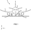
- Aircraft 10 includes a fuselage 11 and wings 13.
- Aircraft 10 includes landing gear such as left landing gear assembly 12, right landing gear assembly 14, and nose landing gear assembly 16 (referred to herein collectively as landing gear assemblies 12, 14, 16).
- Landing gear assemblies 12, 14, 16 may generally support aircraft 10, when aircraft 10 is not flying, allowing aircraft 10 to taxi, take-off, and land without damage.
- Landing gear assemblies 12, 14, 16 may each include various shock and strut assemblies with one or more wheels attached thereto.
- Landing gear assemblies 12, 14, 16 may each be configured to translate between a landing gear down position, wherein the landing gear assemblies extend from wings 13 and/or fuselage 11 to support aircraft 10, and a landing gear up position, wherein the landing gear assemblies are located within wings 13 and/or fuselage 11 of aircraft 10. For example, during taxiing and take-off, and landing, landing gear assemblies 12, 14, 16 may be in the landing gear down position. After take-off, landing gear assemblies 12, 14, 16 may be translated to the landing gear up position. Prior to landing, landing gear assemblies 12, 14, 16 may be translated to the landing gear down position to support aircraft 10 during landing.
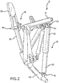
- FIG. 2 components of left landing gear assembly 12 are illustrated, in accordance with various embodiments. While FIGs. 2 , 3A , 3B , 4A and 4B illustrate components of left landing gear assembly 12, it should be understood that right landing gear assembly 14 and nose landing gear assembly 16 may include the elements and functionalities as described herein with respect to left landing gear assembly 12.
- Left landing gear assembly 12 may include one or more shock absorbing devices, such as for example, shock strut 50.
- Shock strut 50 may absorb and damp loads imposed on left landing gear assembly 12 during landing, taxiing, braking, and takeoff.
- Shock strut 50 may include a cylinder and a strut configured to telescope relative to the cylinder.
- Left landing gear assembly 12 may include various linkage assemblies, such as, for example, linkage assembly 58.
- Linkage assembly 58 may be configured to translate left landing gear assembly 12 between the landing gear up and landing gear down positions.
- various components of left landing gear assembly 12 may be coupled to one another via dynamic joints.
- a first strut 60 of linkage assembly 58 may be coupled to a second strut 62 of linkage assembly 58 via a dynamic joint 64.
- a "dynamic joint" refers to a coupling between a first component and a second component, wherein the first component and/or the second component is/are configured to pivot about the dynamic joint such that an angle of the first component relative to the second components changes.
- second strut 62 pivots about dynamic joint 64 such that an angle theta ( ⁇ ) between first strut 60 and second strut 62 changes.
- Left landing gear assembly 12 may include multiple dynamic joints.
- various components of left landing gear assembly 12 may be coupled to one another via static joints.
- an end 74 of shock strut cylinder 52 may be coupled to an upper linkage (or strut) 76 via a static joint 78.
- a static joint refers to a coupling between a first component and a second component, wherein the first and second component do not pivot about the joint.
- the angle between end 74 of shock strut 50 and upper linkage 76 remains relatively constant. While components coupled via a static joint do not rotate, it is further contemplated and understood that the components may exhibit some motion due to structural deflections of the joint generated by loads applied to the landing gear assembly.
- each of the dynamic joints and static joints of left landing gear assembly 12 comprises a first component coupled to a second component via a pin connection.
- each of the dynamic joints and static joints of left landing gear assembly 12 includes a pin located through a first component and through a second component.
- lubricant e.g., grease
- the lubricant may be provided by a lubricant gun fluidly coupled to the inlet of a lubrication channel extending through the first and/or second component to the pin.
- Conventional landing gear components may be formed into the desired shape using traditional manufacturing methods, such as casting, forging, or subtractive manufacturing.
- Lubrication channels are then drilled into the component such that lubricant can be provided to the various component joints during maintenance operations.
- Such techniques tend to limit the potential geometries and locations of lubrication channels.
- an error or misalignment in channel drilling may result in the component being unusable, such that the component must be discarded, resulting in greater cost and manufacturing time.
- Landing gear components of the present disclosure are formed using an additive manufacturing technique.
- Forming the component using additive manufacturing allows lubrication channels to be formed at the time of component formation, as opposed to drilling the lubrication channels after forming the component. Simultaneously forming the component and the lubrication channels may reduce manufacturing time and cost as the potential for drilling error is eliminated.
- Additively manufacturing the lubrication channels also allows for channel designs and geometries that could not be produced through conventional manufacturing.
- additive manufacturing techniques may be employed to form lubrication channels having a curved or angled flow path.
- the lubrication channels may be designed to avoid high stress zones in the component.
- the cross-sectional shape of the lubrication channel may be tailored to reduce stress concentrations in the component.
- additive manufacturing can enable fabrication of complex lubrication channel designs within a landing gear component.
- FIG. 3A and 3B a cross-section view of a dynamic joint 70 of left landing gear assembly 12 is illustrated, in accordance with various embodiments. While FIGs. 3A and 3B illustrate components of dynamic joint 70, it should be understood that any of the dynamic joints of left landing gear assembly 12 may include the elements and functionalities as described herein with respect to dynamic joint 70.
- first landing gear component 100 (referred to herein as first component 100) is coupled to a second landing gear component 102 (referred to herein as second component 102) via a pin 104.
- First component 100 and second component 102 may pivot, relative to one another, about pin 104.
- second component 102 may comprise a strut of shock strut 50 configured to telescope relative to shock strut cylinder 52.
- an end of second component 102 may include a lug 90 disposed around a spherical bearing 92.
- one or more bushing(s) 106 may be located between first component 100 and pin 104.
- pin 104 and bushings 106 have been removed to illustrate details of first and second components 100, 102.
- first component 100 may include a first lug 110 and a second lug 112.
- First lug 110 defines a first pin orifice 114 configured to receive pin 104.
- Second lug 112 may define a second pin orifice 116 configured to receive pin 104.
- Second pin orifice 116 is axially aligned with first pin orifice 114.
- axial refers to a direction parallel to an axis of rotation A-A through a center of pin 104 and first and second lugs 110, 112.
- a first lubrication channel 120 is formed through first component 100.
- First lubrication channel 120 is formed through first lug 110.
- first lug 110 may define, at least, a portion of first lubrication channel 120.
- First lubrication channel 120 provides a flow path for lubricant (e.g., grease), thereby allowing the lubricant to be provided to pin 104.
- First lubrication channel 120 includes an inlet 122 and an outlet 124. Outlet 124 is located at the opposite end of the flow path defined by first lubrication channel 120 as compared to inlet 122.
- lubricant is received by, or input into, first lubrication channel 120 at inlet 122, and is expelled, or output, from first lubrication channel 120 at outlet 124.
- outlet 124 is located at first pin orifice 114.
- outlet 124 may be circumferentially offset, about axis A-A and/or along circumferential surface 115 of first pin orifice 114, from inlet 122.
- the circumferential offset between outlet 124 and inlet 122 may be at least 45°.
- the circumferential offset between outlet 124 and inlet 122 may be at least 90°.
- the circumferential offset between outlet 124 and inlet 122 may be 180°.
- a second lubrication channel 130 may be formed through first component 100.
- second lubrication channel 130 may be formed through second lug 112.
- second lug 112 may define, at least, a portion of second lubrication channel 130.
- Second lubrication channel 130 provides a flow path for lubricant (e.g., grease), thereby allowing the lubricant to be provided to pin 104.
- Second lubrication channel 130 includes an inlet 132 and an outlet 134. Outlet 124 is located at the opposite end of the flow path provided by second lubrication channel 130 as compared to inlet 132.
- lubricant is received by, or input into, second lubrication channel 130 at inlet 132, and is expelled, or output, from second lubrication channel 130 at outlet 134.
- outlet 134 is located at second pin orifice 116.
- Outlets 124, 134 may be radially aligned with a gap 108 in bushings 106.
- radial refers to a direction orthogonal to axis of rotation A-A.
- gap 108 may be formed between two discreate bushing pieces.
- gap 108 may be formed by a first bushing piece 106a that is axially offset with respect to a second bushing piece 106b.
- gap 108 may comprise an opening formed through a single, or one piece, bushing 106.
- inlets 122, 132 may each be configured to receive a lubricant dispenser nipple 140.
- a lubricant dispenser or lubricant "gun" is fluidly coupled to first and second lubrication channels 120, 130 by inserting lubricant dispenser nipples 140 into inlets 122, 132.
- Lubricant from the lubricant dispenser may be provided to first and second lubrication channels 120, 130 through lubricant dispenser nipples 140.
- a threaded fitting 142 may be inserted into each of inlets 122, 132. Threaded fittings 142 may engage a threaded portion of lubricant dispenser nipples 140.
- threaded fittings 142 may be press fit into inlets 122, 132.
- First component 100 is formed using additive manufacturing.
- first component 100 may be formed using wire arc additive manufacturing, electron beam additive manufacturing, or any other suitable additive manufacturing technique. Forming first component 100 using additive manufacturing allows the flow paths defined by first and second lubrication channels 120, 130 to be curved and/or angled and/or include bends.
- lubricant may flow axially, radially, and/or circumferentially between inlets 122, 132 and outlets 124, 134 of first and second lubrication channels 120, 130.
- the geometry of first and second lubrication channels 120, 130 may to be selected to avoid high stress zones.
- first and second lubrication channels 120, 130 through first and second lugs 110, 112 may be selected based on the loads and stresses experienced by first and second lugs 110, 112.
- the paths of first and second lubrication channels 120, 130 through first and second lugs 110, 112 may be selected to avoid high stress zones.
- the first and second lubrication channels 120, 130 may be designed to avoid areas of first and second lugs 110, 112 that experience increased stress during translation between the landing gear up and landing gear down position and/or to avoid areas that experience increased stress from loads generated during, for example, aircraft landing.
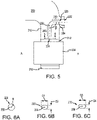
- Additively manufactured component 200 includes a lug 210 defining a pin orifice 212. Pin orifice 212 is configured to receive pin 204.
- Additively manufactured component 200 may comprise a landing gear component, similar to, for example, first landing gear component 100 in FIGs. 3A and 3B .
- first and second lubrication channels 120, 130 in FIGs. 3A and 3B may include the elements and functionalities as described herein with reference to lubrication channel 220.
- second component 102 in FIGs. 3A and 3B may be additively manufactured having a lubrication channel formed through lug 90 and including the elements and functionalities as described herein with reference to lubrication channel 220.
- Lubrication channel 220 includes an inlet 222 and an outlet 224.
- Outlet 224 is located at the opposite end of the flow path defined by lubrication channel 220 as compared to inlet 222.
- lubricant is received by lubrication channel 220 at inlet 222, and is output from lubrication channel 220 at outlet 224.
- outlet 224 is located at pin orifice 212.
- inlet 222 may be configured to receive a lubricant dispenser nipple.
- Lubrication channel 220 is oriented (i.e., a geometry of lubrication channel 220 is selected) to avoid high stress areas in lug 210.
- lubrication channel 220 may be curved, angled, and/or include a bend.
- a first portion 250 of lubrication channel 220 is oriented at an angle beta ( ⁇ ) relative to a second portion 252 of lubrication channel 220.
- a center axis 254 of first portion 250 is oriented at angle beta ( ⁇ ) relative to a center axis 256 of second portion 252.
- the angle beta ( ⁇ ) is less than 180°.
- angle beta ( ⁇ ) may be between 20° and 160°.
- angle beta ( ⁇ ) may be between 45° and 135°. In various embodiments, angle beta may be between 90° and 160°. While lubrication channel 220 is illustrated as having one approximately 90° bend, it is further contemplated and understood and lubrication channel 220 may include any number of bends oriented at any desired angle. Additionally, in various embodiments, lubrication channel 220 may be curved and/or have a circumferential or semi-circular geometry, as additive manufacturing can generate curved flow paths. For example, in various embodiments, portions of lubrication channel 220 may mirror the curvature of pin orifice 212 about axis A-A.
- the cross-sectional shape of lubrication channel 220 may be tailored to reduce stress concentrations in additively manufactured component 200.
- a cross-section of second portion 252, taken along a plane perpendicular to center axis 256, may comprise a circle having a radius R as measured from center axis 256.
- a cross-section of second portion 252, taken along a plane perpendicular to center axis 256, may comprise an oblong shape, for example, an oval or a race track, wherein a first dimension D1 of the cross-section is greater than a second dimension D2 of the cross-section, wherein the second dimension is perpendicular to the first dimension D1.
- a cross-section of second portion 252, taken along a plane perpendicular to center axis 256, may comprise an oval-shape such that first dimension D1 of the cross-section is greater than second dimension D2 of the cross-section.
- a cross-section of second portion 252, taken along a plane perpendicular to center axis 256, may comprise a race track shape having two parallel walls and two semi-circular, or curved, walls at opposing ends of the parallel wall, and wherein a first dimension D3 of the cross-section is greater than a second dimension D4 of the cross-section.
- first portion 250 of lubrication channel 220 may comprise a circular cross-section, as taken in a plane perpendicular to center axis 254, and second portion 252 of lubrication channel 220 may comprise an oblong cross-section.
- second portion 252 may have a race track shape cross-section and outlet 224 of lubrication channel 220 may comprise an oval shape cross-section.
- a first section of second portion 252 may have a race track shape cross-section with the greater dimension D3 oriented in an axial direction parallel to axis A-A and a second section of second portion 252 may have a race track shape cross-section with the smaller dimension D4 oriented in the axial direction.
- Lubrication channel 220 may include any number and/or combination of cross-section geometries between inlet 222 and outlet 224.
- FIGs. 4A and 4B a cross-section view of a static joint 270 of left landing gear assembly 12 is illustrated, in accordance with various embodiments. While FIGs. 4A and 4B illustrate components of static joint 270, it should be understood that any of the static joints of left landing gear assembly 12 may include the elements and functionalities as described herein with respect to static joint 270.
- first landing gear component 300 (referred to herein as first component 300) is coupled to a second landing gear component 302 (referred to herein as second component 302) via a pin 304.
- second component 302 (referred to herein as second component 302)
- one or more bushing(s) 306 may be located between pin 304 and first and second components 300, 302.
- pin 304 and bushings 306 have been removed to illustrate details of first and second components 300, 302.
- first component 300 may include a first inner lug 310 and a second inner lug 312.
- First inner lug 310 may define a first inner pin orifice 314 configured to receive pin 304.
- Second inner lug 312 may define a second inner pin orifice 316 configured to receive pin 304.
- Second inner pin orifice 316 is axially aligned with first inner pin orifice 314.
- "axial" refers to a direction parallel to a center axis of B-B of pin 304.
- second component 302 may include a first outer lug 340 and a second outer lug 342.
- First outer lug 340 may define a first outer pin orifice 344 configured to receive pin 304.
- Second outer lug 342 may define a second outer pin orifice 346 configured to receive pin 304.
- Second outer pin orifice 346 is axially aligned with first outer pin orifice 344.
- First and second outer pin orifices 344, 346 may also be axial aligned with first and second inner pin orifices 314, 316.
- "axial" refers to a direction parallel to a center axis of B-B of pin 304.
- a first lubrication channel 320 may be formed through first inner lug 310. Stated differently, first inner lug 310 may define, at least, a portion of first lubrication channel 320.
- First lubrication channel 320 provides a flow path for lubricant (e.g., grease), thereby allowing the lubricant to be provided between pin 304 and first inner lug 310.
- First lubrication channel 320 includes an inlet 322 and an first outlet 324.
- first lubrication channel 320 may comprise a second outlet 326 fluidly coupled to inlet 322. First and second outlets 324, 326 are each located at first inner pin orifice 314.
- first lubrication channel 320 may comprise a network of fluidly coupled conduits with each conduit having an outlet located at first inner pin orifice 314.
- second outlet 326 may be circumferentially offset, as measured about axis B-B and/or along circumferential surface 315 of first inner pin orifice 314, from first outlet 324.
- the circumferential offset between second outlet 326 and first outlet 324 may be at least 45°.
- the circumferential offset between second outlet 326 and first outlet 324 may be at least 90°.
- the circumferential offset between second outlet 326 and first outlet 324 may be 180°.
- first outlet 324 may be circumferentially offset, as measured about axis B-B and/or along circumferential surface 315 of first inner pin orifice 314, from inlet 322.
- a second lubrication channel 330 may be formed through second inner lug 312. Stated differently, second inner lug 312 may define, at least, a portion of second lubrication channel 330. Second lubrication channel 330 provides a flow path for lubricant (e.g., grease), thereby allowing the lubricant to be provided between pin 304 and second inner lug 312. Second lubrication channel 330 includes an inlet 332 and a first outlet 334. In various embodiments, second lubrication channel 330 may comprise a second outlet 336 fluidly coupled to inlet 322. First and second outlets 334, 336 are each located at second inner pin orifice 316. In various embodiments, second lubrication channel 330 a comprise a network of fluidly coupled conduits with each conduit having an outlet at second inner pin orifice 316.
- lubrication channel 330 a comprise a network of fluidly coupled conduits with each conduit having an outlet at second inner pin orifice 316.
- second outlet 336 may be circumferentially offset, as measured about axis B-B and/or along circumferential surface 317 of second inner pin orifice 316, from first outlet 324. In various embodiments, the circumferential offset between second outlet 336 and first outlet 334 may be at least 45°. In various embodiments, the circumferential offset between second outlet 336 and first outlet 334 may be at least 90°. In various embodiments, the circumferential offset between second outlet 336 and first outlet 334 may be 180°. In various embodiments, first outlet 334 may be circumferentially offset, as measured about axis B-B and/or along circumferential surface 317 of second inner pin orifice 316, from inlet 332.
- a first lubrication channel 350 may be formed through first outer lug 340 of second component 302.
- First lubrication channel 350 includes an outlet 354 located at first outer pin orifice 344.
- First lubrication channel 350 provides a flow path for lubricant (e.g., grease), thereby allowing lubricant to be provided between pin 304 and first outer lug 340.
- lubricant e.g., grease
- a second lubrication channel 360 may be formed through second outer lug 342.
- Second lubrication channel 360 includes an outlet 364 located at second outer pin orifice 346.
- Second lubrication channel 360 provides a flow path for lubricant (e.g., grease), thereby allowing lubricant to be provided between pin 304 and second outer lug 342.
- lubricant e.g., grease
- First lubrication channel 350 and second lubrication channel 360 may both be fluidly couple to an inlet 362 defined by second component 302.
- lubricant is received by first lubrication channel 350 and second lubrication channel 360 at inlet 362, and is output from first lubrication channel 350 at outlet 354. and from second lubrication channel 360 at outlet 364
- inlets 322, 332, and 362 may each be configured to receive a lubricant dispenser nipple.
- a threaded bushing configured to engage a threaded lubricant dispenser nipple may be press fit into inlets 322, 332, and 362.
- First component 300 and second component 302 are each formed using additive manufacturing.
- first component 300 and second component 302 may be formed using wire arc additive manufacturing, electron beam additive manufacturing, or any other suitable additive manufacturing technique.
- Forming first and second components 300, 302 using additive manufacturing allows the flow paths defined by lubrication channels 320, 330, 350, 360 to be curved and/or angled and/or include bends.
- lubricant may flow axially, radially, and/or circumferentially between the inlet and the outlet of the lubrication channel.
- lubrication channels 320, 330, 350, 360 may each include the elements and functionalities as described herein with reference to lubrication channel 220 in FIG. 5 .
- first and second lubrication channels 320, 330, 350, 360 may be selected to avoid high stress zones.
- the paths of first and second lubrication channels 320, 330 may be selected based on the loads and stresses experienced by first and second inner lugs 310, 312.
- first and second lubrication channels 320, 330 may be designed to avoid areas of first and second inner lugs 310, 312 that experience increased stress during translation between the landing gear up and landing gear down position and/or to avoid areas that experience increased stress from loads generated during, for example, aircraft landing.
- the paths of first and second lubrication channels 350, 360 may be selected based on the loads and stresses experienced by first and second outer lugs 340, 342.
- first and second lubrication channels 350, 360 may be designed to avoid areas of first and second outer lugs 340, 342 that experience increased stress during translation between the landing gear up and landing gear down position and/or to avoid areas that experience increased stress from loads generated during, for example, aircraft landing.
- references to "one embodiment,” “an embodiment,” “various embodiments,” etc. indicate that the embodiment described may include a particular feature, structure, or characteristic, but every embodiment may not necessarily include the particular feature, structure, or characteristic. Moreover, such phrases are not necessarily referring to the same embodiment. Further, when a particular feature, structure, or characteristic is described in connection with an embodiment, it is submitted that it is within the knowledge of one skilled in the art to affect such feature, structure, or characteristic in connection with other embodiments whether or not explicitly described. After reading the description, it will be apparent to one skilled in the relevant art(s) how to implement the disclosure in alternative embodiments.
Landscapes
- Engineering & Computer Science (AREA)
- Mechanical Engineering (AREA)
- Manufacturing & Machinery (AREA)
- General Engineering & Computer Science (AREA)
- Aviation & Aerospace Engineering (AREA)
- Chemical & Material Sciences (AREA)
- Materials Engineering (AREA)
- Physics & Mathematics (AREA)
- Optics & Photonics (AREA)
- Transportation (AREA)
- General Details Of Gearings (AREA)
Claims (15)
- Additiv gefertigtes Bauteil für eine Fahrwerksbaugruppe, wobei das additiv gefertigte Bauteil Folgendes umfasst:einen ersten Ansatz (110), der eine erste Stiftöffnung (114) definiert; undeinen ersten Schmierkanal (120), der sich durch den ersten Ansatz erstreckt, wobei der erste Schmierkanal einen Einlass (122) und einen Auslass (124) umfasst, wobei sich der Auslass an der ersten Stiftöffnung befindet und wobei eine Mittelachse eines ersten Abschnitts des ersten Schmierkanals in einem ersten Winkel relativ zu einer Mittelachse eines zweiten Abschnitts des ersten Schmierkanals ausgerichtet ist, wobei der erste Winkel kleiner als 180° ist.
- Additiv gefertigtes Bauteil nach Anspruch 1, wobei ein Querschnitt des zweiten Abschnitts des ersten Schmierkanals eine längliche Form umfasst, die eine erste Abmessung aufweist, die größer als eine zweite Abmessung ist, wobei der Querschnitt des zweiten Abschnitts entlang einer Ebene senkrecht zur Mittelachse des zweiten Abschnitts herangezogen wird.
- Additiv gefertigtes Bauteil nach Anspruch 1, wobei eine Form eines Querschnitts des ersten Abschnitts des ersten Schmierkanals sich von einer Form eines Querschnitts des zweiten Abschnitts des ersten Schmierkanals unterscheidet, wobei der Querschnitt des ersten Abschnitts entlang einer Ebene herangezogen wird, die senkrecht zu der Mittelachse des ersten Abschnitts verläuft, und der Querschnitt des zweiten Abschnitts entlang einer Ebene herangezogen wird, die senkrecht zu der Mittelachse des zweiten Abschnitts verläuft.
- Additiv gefertigtes Bauteil nach einem vorhergehenden Anspruch, wobei der Einlass des ersten Schmierkanals in Umfangsrichtung entlang einer Umfangsfläche der ersten Stiftöffnung von dem Auslass des ersten Schmierkanals versetzt ist.
- Additiv hergestelltes Bauteil nach einem vorhergehenden Anspruch, ferner umfassend:einen zweiten Ansatz (112), der eine zweite Stiftöffnung (116) definiert, die axial mit der ersten Stiftöffnung ausgerichtet ist; undeinen zweiten Schmierkanal (130), der sich durch den zweiten Ansatz erstreckt, und wobei optional eine Mittelachse eines ersten Abschnitts des zweiten Schmierkanals in einem zweiten Winkel relativ zu einer Mittelachse eines zweiten Abschnitts des zweiten Schmierkanals ausgerichtet ist und wobei der zweite Winkel kleiner als 180° ist.
- Additiv gefertigtes Bauteil nach Anspruch 5, wobei der zweite Schmierkanal mit dem Einlass des ersten Schmierkanals fluidisch verbunden ist.
- Fahrwerksbaugruppe, umfassend:
ein additiv hergestelltes Bauteil nach Anspruch 1, wobei das Bauteil ferner Folgendes umfasst:einen zweiten Ansatz (112), der eine zweite Stiftöffnung (116) definiert; undeinen Stift (104), der durch die erste Stiftöffnung und die zweite Stiftöffnung angeordnet ist. - Fahrwerksbaugruppe nach Anspruch 7, wobei ein Querschnitt des zweiten Abschnitts des ersten Schmierkanals eine längliche Form umfasst, die eine erste Abmessung aufweist, die größer als eine zweite Abmessung ist, wobei der Querschnitt des zweiten Abschnitts des ersten Schmierkanals entlang einer Ebene herangezogen wird, die senkrecht zur Mittelachse des zweiten Abschnitts des ersten Schmierkanals verläuft, und/oder wobei sich eine Form eines Querschnitts des ersten Abschnitts des ersten Schmierkanals von einer Form eines Querschnitts des ersten Auslasses des ersten Schmierkanals unterscheidet, wobei der Querschnitt des ersten Abschnitts des ersten Schmierkanals entlang einer Ebene senkrecht zur Mittelachse des ersten Abschnitts des ersten Schmierkanals herangezogen wird und der Querschnitt des ersten Auslasses des ersten Schmierkanals in einer Ebene senkrecht zur Mittelachse des zweiten Abschnitts des ersten Schmierkanals herangezogen wird.
- Fahrwerksbaugruppe nach Anspruch 7 oder 8, ferner einen zweiten Schmierkanal umfassend, der durch den zweiten Ansatz definiert ist, und wobei optional eine Mittelachse eines ersten Abschnitts des zweiten Schmierkanals in einem zweiten Winkel relativ zu einer Mittelachse eines zweiten Abschnitts des zweiten Schmierkanals ausgerichtet ist und wobei der zweite Winkel kleiner als 180° ist.
- Fahrwerksbaugruppe nach einem der Ansprüche 7 bis 9, wobei der Einlass des ersten Schmierkanals in Umfangsrichtung um eine Drehachse des Stifts von dem ersten Auslass des ersten Schmierkanals versetzt ist.
- Fahrwerksbaugruppe nach einem der Ansprüche 7 bis 10, wobei der erste Schmierkanal ferner einen zweiten Auslass beinhaltet, der sich an der ersten Stiftöffnung befindet, und/oder wobei der erste Auslass in Umfangsrichtung von dem zweiten Auslass versetzt ist.
- Verfahren zum Bilden eines Fahrwerksbauteils, umfassend:
Bilden des Fahrwerksbauteils unter Verwendung von additiver Fertigung, wobei das Fahrwerksbauteil Folgendes umfasst:einen ersten Ansatz, der eine erste Stiftöffnung definiert; undeinen ersten Schmierkanal, der sich durch den ersten Ansatz erstreckt, wobei der erste Schmierkanal einen Einlass und einen Auslass umfasst, wobei sich der Auslass an der ersten Stiftöffnung befindet und wobei eine Mittelachse eines ersten Abschnitts des ersten Schmierkanals in einem Winkel kleiner als 180° relativ zu einer Mittelachse eines zweiten Abschnitts des ersten Schmierkanals ausgerichtet ist. - Verfahren nach Anspruch 12, wobei das Bilden des Fahrwerksbauteils umfasst:Bilden des ersten Abschnitts des ersten Schmierkanals, der eine erste Querschnittsform aufweist, wobei die erste Querschnittsform in einer Ebene herangezogen wird, die senkrecht zu der Mittelachse des ersten Abschnitts des Schmierkanals liegt; undBilden des zweiten Abschnitts des ersten Schmierkanals, der eine zweite Querschnittsform umfasst, die sich von der ersten Querschnittsform unterscheidet, wobei die zweite Querschnittsform in einer Ebene senkrecht zu der Mittelachse des zweiten Abschnitts des ersten Schmierkanals herangezogen wird.
- Verfahren nach Anspruch 13, wobei das Fahrwerksbauteil ferner Folgendes umfasst:einen zweiten Ansatz, der eine zweite Stiftöffnung definiert; undeinen zweiten Schmierkanal, der sich durch den zweiten Ansatz erstreckt, wobei der zweite Schmierkanal einen zweiten Auslass umfasst, der sich an der zweiten Stiftöffnung befindet.
- Verfahren nach Anspruch 12, wobei der Auslass des ersten Schmierkanals in Umfangsrichtung entlang einer Umfangsfläche der ersten Stiftöffnung relativ zum Einlass des ersten Schmierkanals versetzt ist.
Applications Claiming Priority (1)
| Application Number | Priority Date | Filing Date | Title |
|---|---|---|---|
| US16/408,944 US11167865B2 (en) | 2019-05-10 | 2019-05-10 | Additively manufactured lubrication channels |
Publications (2)
| Publication Number | Publication Date |
|---|---|
| EP3736065A1 EP3736065A1 (de) | 2020-11-11 |
| EP3736065B1 true EP3736065B1 (de) | 2022-10-26 |
Family
ID=68848127
Family Applications (1)
| Application Number | Title | Priority Date | Filing Date |
|---|---|---|---|
| EP19214967.2A Active EP3736065B1 (de) | 2019-05-10 | 2019-12-10 | Additiv gefertigte schmierkanäle |
Country Status (2)
| Country | Link |
|---|---|
| US (1) | US11167865B2 (de) |
| EP (1) | EP3736065B1 (de) |
Families Citing this family (3)
| Publication number | Priority date | Publication date | Assignee | Title |
|---|---|---|---|---|
| FR3106170B1 (fr) * | 2020-01-10 | 2021-12-24 | Safran Landing Systems | Olive pour crochet de verrouillage |
| US12253112B2 (en) * | 2022-11-10 | 2025-03-18 | Goodrich Corporation | 3D printed bushing with printed grease passages and lube fittings incorporated |
| GB2641797A (en) * | 2024-06-13 | 2025-12-17 | Safran Landing Systems Uk Ltd | Lubrication sensor |
Family Cites Families (19)
| Publication number | Priority date | Publication date | Assignee | Title |
|---|---|---|---|---|
| US2659615A (en) | 1949-06-21 | 1953-11-17 | Lockheed Aircraft Corp | Dual hydraulic swivel joint |
| US2792998A (en) | 1952-10-23 | 1957-05-21 | Dowty Equipment Ltd | Brake system on aircraft multi-wheel bogie undercarriage |
| US6016995A (en) * | 1997-08-26 | 2000-01-25 | The Boeing Company | Aircraft nose landing gear |
| US6409121B1 (en) * | 2000-08-30 | 2002-06-25 | The Boeing Company | In flight autolubrication system for the mechanical members of aircraft landing gear |
| US7264398B2 (en) * | 2001-08-24 | 2007-09-04 | The Boeing Company | Truck pivot joint bearing and method of lubricating |
| GB2508043B (en) * | 2013-04-17 | 2015-07-22 | Messier Dowty Ltd | Dynamic bearing |
| US9140302B2 (en) * | 2013-06-13 | 2015-09-22 | The Boeing Company | Joint bearing lubricant system |
| US20160199913A1 (en) | 2013-09-04 | 2016-07-14 | Bae Systems Plc | Conduit system |
| GB2521392A (en) | 2013-12-18 | 2015-06-24 | Skf Ab | Method of producing a raceway ring, inner ring or outer ring, and raceway ring |
| EP2918358B1 (de) | 2014-03-12 | 2017-06-21 | Safran Landing Systems UK Limited | Verfahren zur Herstellung eines Bauteils umfassend Fliessdrücken |
| US9958068B2 (en) | 2014-03-21 | 2018-05-01 | Goodrich Corporation | Piston housing system and apparatus |
| EP2947338B1 (de) | 2014-05-20 | 2016-11-02 | SKF Aerospace France | Kugelförmiges Gleitlager, Lageranordnung und Verfahren zur Herstellung eines solchen Lagers |
| US20160047412A1 (en) * | 2014-08-12 | 2016-02-18 | The Boeing Company | Enhanced thermally conductive pivot bushing |
| US10486799B2 (en) | 2016-04-29 | 2019-11-26 | Goodrich Corporation | Rod end |
| US10933981B2 (en) * | 2016-06-21 | 2021-03-02 | Goodrich Corporation | Aerodynamic noise reducing thin-skin landing gear structures and manufacturing techniques |
| US10563690B2 (en) | 2016-07-28 | 2020-02-18 | Goodrich Corporation | Thin-skin side stay beams and landing gear assemblies |
| IT201600108934A1 (it) | 2016-10-27 | 2018-04-27 | Nuovo Pignone Tecnologie Srl | Cuscinetto a pattini oscillanti e metodo per la sua fabbricazione |
| DE102016222411A1 (de) | 2016-11-15 | 2018-05-17 | Schaeffler Technologies AG & Co. KG | Schmiermittelzuführbauteil |
| CN109533296A (zh) | 2018-11-09 | 2019-03-29 | 中国直升机设计研究所 | 一种机身与起落架摇臂的连接结构 |
-
2019
- 2019-05-10 US US16/408,944 patent/US11167865B2/en active Active
- 2019-12-10 EP EP19214967.2A patent/EP3736065B1/de active Active
Also Published As
| Publication number | Publication date |
|---|---|
| US11167865B2 (en) | 2021-11-09 |
| US20200354085A1 (en) | 2020-11-12 |
| EP3736065A1 (de) | 2020-11-11 |
Similar Documents
| Publication | Publication Date | Title |
|---|---|---|
| EP3736065B1 (de) | Additiv gefertigte schmierkanäle | |
| US8475114B2 (en) | Air cycle machine air bearing shaft | |
| EP3062021B1 (de) | Brennstoffdüse | |
| US11585236B2 (en) | Turbojet bearing support produced by additive manufacturing | |
| EP2947338B1 (de) | Kugelförmiges Gleitlager, Lageranordnung und Verfahren zur Herstellung eines solchen Lagers | |
| CN111971137A (zh) | 对用于具有凹部的部件的增材制造的支撑件进行的优化 | |
| EP3342704B1 (de) | Steckbuchsenanordnung | |
| EP3736210B1 (de) | Fahrwerk mit hydraulikflüssigkeitskanälen | |
| EP2503107B1 (de) | Lageranordnung, Strömungsmaschine sowie Verfahren | |
| EP4368502B1 (de) | 3d-gedruckte buchse mit gedruckten fettpassagen und integrierten schmierarmaturen | |
| CN107448250B (zh) | 涡轮机对准键以及相关涡轮机 | |
| EP3839314B1 (de) | Optimierungssystem für kardanische abstände | |
| EP4215768B1 (de) | Leckresistente nachgiebige buchse | |
| EP2886206B1 (de) | Verfahren zur Beschichtung einer Buchse | |
| US12498069B2 (en) | Additive manufactured hydraulic swivel bolt; and method | |
| CN107269397A (zh) | 一种轻质轴承座结构 | |
| US20260126106A1 (en) | Additively manufactured gears for aerospace and defense | |
| JP6801255B2 (ja) | ハブユニットの製造方法 | |
| EP4589122A1 (de) | Verfahren zur herstellung eines gasturbinenmotorlagergehäuses | |
| EP2815963B1 (de) | Gewichtsreduzierungsmerkmale von Fahrwerken | |
| BR102023021401A2 (pt) | Bucha para uso em uma aeronave, conjunto de trem de pouso, e, método para impressão 3d de uma bucha | |
| EP3324090B1 (de) | Verstellpropeller mit übertragungsrohr |
Legal Events
| Date | Code | Title | Description |
|---|---|---|---|
| PUAI | Public reference made under article 153(3) epc to a published international application that has entered the european phase |
Free format text: ORIGINAL CODE: 0009012 |
|
| STAA | Information on the status of an ep patent application or granted ep patent |
Free format text: STATUS: THE APPLICATION HAS BEEN PUBLISHED |
|
| AK | Designated contracting states |
Kind code of ref document: A1 Designated state(s): AL AT BE BG CH CY CZ DE DK EE ES FI FR GB GR HR HU IE IS IT LI LT LU LV MC MK MT NL NO PL PT RO RS SE SI SK SM TR |
|
| AX | Request for extension of the european patent |
Extension state: BA ME |
|
| STAA | Information on the status of an ep patent application or granted ep patent |
Free format text: STATUS: REQUEST FOR EXAMINATION WAS MADE |
|
| 17P | Request for examination filed |
Effective date: 20210511 |
|
| RBV | Designated contracting states (corrected) |
Designated state(s): AL AT BE BG CH CY CZ DE DK EE ES FI FR GB GR HR HU IE IS IT LI LT LU LV MC MK MT NL NO PL PT RO RS SE SI SK SM TR |
|
| GRAP | Despatch of communication of intention to grant a patent |
Free format text: ORIGINAL CODE: EPIDOSNIGR1 |
|
| STAA | Information on the status of an ep patent application or granted ep patent |
Free format text: STATUS: GRANT OF PATENT IS INTENDED |
|
| RIC1 | Information provided on ipc code assigned before grant |
Ipc: B33Y 80/00 20150101ALI20220425BHEP Ipc: F16N 7/00 20060101ALI20220425BHEP Ipc: F16N 21/02 20060101ALI20220425BHEP Ipc: F16N 1/00 20060101ALI20220425BHEP Ipc: B64C 25/34 20060101ALI20220425BHEP Ipc: B64C 25/02 20060101ALI20220425BHEP Ipc: B22F 5/10 20060101ALI20220425BHEP Ipc: B22F 5/00 20060101AFI20220425BHEP |
|
| INTG | Intention to grant announced |
Effective date: 20220518 |
|
| GRAS | Grant fee paid |
Free format text: ORIGINAL CODE: EPIDOSNIGR3 |
|
| GRAA | (expected) grant |
Free format text: ORIGINAL CODE: 0009210 |
|
| STAA | Information on the status of an ep patent application or granted ep patent |
Free format text: STATUS: THE PATENT HAS BEEN GRANTED |
|
| AK | Designated contracting states |
Kind code of ref document: B1 Designated state(s): AL AT BE BG CH CY CZ DE DK EE ES FI FR GB GR HR HU IE IS IT LI LT LU LV MC MK MT NL NO PL PT RO RS SE SI SK SM TR |
|
| REG | Reference to a national code |
Ref country code: GB Ref legal event code: FG4D |
|
| REG | Reference to a national code |
Ref country code: CH Ref legal event code: EP |
|
| REG | Reference to a national code |
Ref country code: DE Ref legal event code: R096 Ref document number: 602019021056 Country of ref document: DE |
|
| REG | Reference to a national code |
Ref country code: AT Ref legal event code: REF Ref document number: 1526686 Country of ref document: AT Kind code of ref document: T Effective date: 20221115 |
|
| REG | Reference to a national code |
Ref country code: IE Ref legal event code: FG4D |
|
| REG | Reference to a national code |
Ref country code: LT Ref legal event code: MG9D |
|
| REG | Reference to a national code |
Ref country code: NL Ref legal event code: MP Effective date: 20221026 |
|
| REG | Reference to a national code |
Ref country code: AT Ref legal event code: MK05 Ref document number: 1526686 Country of ref document: AT Kind code of ref document: T Effective date: 20221026 |
|
| PG25 | Lapsed in a contracting state [announced via postgrant information from national office to epo] |
Ref country code: NL Free format text: LAPSE BECAUSE OF FAILURE TO SUBMIT A TRANSLATION OF THE DESCRIPTION OR TO PAY THE FEE WITHIN THE PRESCRIBED TIME-LIMIT Effective date: 20221026 |
|
| PG25 | Lapsed in a contracting state [announced via postgrant information from national office to epo] |
Ref country code: SE Free format text: LAPSE BECAUSE OF FAILURE TO SUBMIT A TRANSLATION OF THE DESCRIPTION OR TO PAY THE FEE WITHIN THE PRESCRIBED TIME-LIMIT Effective date: 20221026 Ref country code: PT Free format text: LAPSE BECAUSE OF FAILURE TO SUBMIT A TRANSLATION OF THE DESCRIPTION OR TO PAY THE FEE WITHIN THE PRESCRIBED TIME-LIMIT Effective date: 20230227 Ref country code: NO Free format text: LAPSE BECAUSE OF FAILURE TO SUBMIT A TRANSLATION OF THE DESCRIPTION OR TO PAY THE FEE WITHIN THE PRESCRIBED TIME-LIMIT Effective date: 20230126 Ref country code: LT Free format text: LAPSE BECAUSE OF FAILURE TO SUBMIT A TRANSLATION OF THE DESCRIPTION OR TO PAY THE FEE WITHIN THE PRESCRIBED TIME-LIMIT Effective date: 20221026 Ref country code: FI Free format text: LAPSE BECAUSE OF FAILURE TO SUBMIT A TRANSLATION OF THE DESCRIPTION OR TO PAY THE FEE WITHIN THE PRESCRIBED TIME-LIMIT Effective date: 20221026 Ref country code: ES Free format text: LAPSE BECAUSE OF FAILURE TO SUBMIT A TRANSLATION OF THE DESCRIPTION OR TO PAY THE FEE WITHIN THE PRESCRIBED TIME-LIMIT Effective date: 20221026 Ref country code: AT Free format text: LAPSE BECAUSE OF FAILURE TO SUBMIT A TRANSLATION OF THE DESCRIPTION OR TO PAY THE FEE WITHIN THE PRESCRIBED TIME-LIMIT Effective date: 20221026 |
|
| PG25 | Lapsed in a contracting state [announced via postgrant information from national office to epo] |
Ref country code: RS Free format text: LAPSE BECAUSE OF FAILURE TO SUBMIT A TRANSLATION OF THE DESCRIPTION OR TO PAY THE FEE WITHIN THE PRESCRIBED TIME-LIMIT Effective date: 20221026 Ref country code: PL Free format text: LAPSE BECAUSE OF FAILURE TO SUBMIT A TRANSLATION OF THE DESCRIPTION OR TO PAY THE FEE WITHIN THE PRESCRIBED TIME-LIMIT Effective date: 20221026 Ref country code: LV Free format text: LAPSE BECAUSE OF FAILURE TO SUBMIT A TRANSLATION OF THE DESCRIPTION OR TO PAY THE FEE WITHIN THE PRESCRIBED TIME-LIMIT Effective date: 20221026 Ref country code: IS Free format text: LAPSE BECAUSE OF FAILURE TO SUBMIT A TRANSLATION OF THE DESCRIPTION OR TO PAY THE FEE WITHIN THE PRESCRIBED TIME-LIMIT Effective date: 20230226 Ref country code: HR Free format text: LAPSE BECAUSE OF FAILURE TO SUBMIT A TRANSLATION OF THE DESCRIPTION OR TO PAY THE FEE WITHIN THE PRESCRIBED TIME-LIMIT Effective date: 20221026 Ref country code: GR Free format text: LAPSE BECAUSE OF FAILURE TO SUBMIT A TRANSLATION OF THE DESCRIPTION OR TO PAY THE FEE WITHIN THE PRESCRIBED TIME-LIMIT Effective date: 20230127 |
|
| P01 | Opt-out of the competence of the unified patent court (upc) registered |
Effective date: 20230522 |
|
| REG | Reference to a national code |
Ref country code: DE Ref legal event code: R097 Ref document number: 602019021056 Country of ref document: DE |
|
| PG25 | Lapsed in a contracting state [announced via postgrant information from national office to epo] |
Ref country code: SM Free format text: LAPSE BECAUSE OF FAILURE TO SUBMIT A TRANSLATION OF THE DESCRIPTION OR TO PAY THE FEE WITHIN THE PRESCRIBED TIME-LIMIT Effective date: 20221026 Ref country code: RO Free format text: LAPSE BECAUSE OF FAILURE TO SUBMIT A TRANSLATION OF THE DESCRIPTION OR TO PAY THE FEE WITHIN THE PRESCRIBED TIME-LIMIT Effective date: 20221026 Ref country code: EE Free format text: LAPSE BECAUSE OF FAILURE TO SUBMIT A TRANSLATION OF THE DESCRIPTION OR TO PAY THE FEE WITHIN THE PRESCRIBED TIME-LIMIT Effective date: 20221026 Ref country code: DK Free format text: LAPSE BECAUSE OF FAILURE TO SUBMIT A TRANSLATION OF THE DESCRIPTION OR TO PAY THE FEE WITHIN THE PRESCRIBED TIME-LIMIT Effective date: 20221026 Ref country code: CZ Free format text: LAPSE BECAUSE OF FAILURE TO SUBMIT A TRANSLATION OF THE DESCRIPTION OR TO PAY THE FEE WITHIN THE PRESCRIBED TIME-LIMIT Effective date: 20221026 |
|
| REG | Reference to a national code |
Ref country code: CH Ref legal event code: PL |
|
| REG | Reference to a national code |
Ref country code: BE Ref legal event code: MM Effective date: 20221231 |
|
| PG25 | Lapsed in a contracting state [announced via postgrant information from national office to epo] |
Ref country code: SK Free format text: LAPSE BECAUSE OF FAILURE TO SUBMIT A TRANSLATION OF THE DESCRIPTION OR TO PAY THE FEE WITHIN THE PRESCRIBED TIME-LIMIT Effective date: 20221026 Ref country code: LU Free format text: LAPSE BECAUSE OF NON-PAYMENT OF DUE FEES Effective date: 20221210 Ref country code: AL Free format text: LAPSE BECAUSE OF FAILURE TO SUBMIT A TRANSLATION OF THE DESCRIPTION OR TO PAY THE FEE WITHIN THE PRESCRIBED TIME-LIMIT Effective date: 20221026 |
|
| PLBE | No opposition filed within time limit |
Free format text: ORIGINAL CODE: 0009261 |
|
| STAA | Information on the status of an ep patent application or granted ep patent |
Free format text: STATUS: NO OPPOSITION FILED WITHIN TIME LIMIT |
|
| 26N | No opposition filed |
Effective date: 20230727 |
|
| PG25 | Lapsed in a contracting state [announced via postgrant information from national office to epo] |
Ref country code: LI Free format text: LAPSE BECAUSE OF NON-PAYMENT OF DUE FEES Effective date: 20221231 Ref country code: IE Free format text: LAPSE BECAUSE OF NON-PAYMENT OF DUE FEES Effective date: 20221210 Ref country code: CH Free format text: LAPSE BECAUSE OF NON-PAYMENT OF DUE FEES Effective date: 20221231 |
|
| PG25 | Lapsed in a contracting state [announced via postgrant information from national office to epo] |
Ref country code: SI Free format text: LAPSE BECAUSE OF FAILURE TO SUBMIT A TRANSLATION OF THE DESCRIPTION OR TO PAY THE FEE WITHIN THE PRESCRIBED TIME-LIMIT Effective date: 20221026 Ref country code: BE Free format text: LAPSE BECAUSE OF NON-PAYMENT OF DUE FEES Effective date: 20221231 |
|
| PG25 | Lapsed in a contracting state [announced via postgrant information from national office to epo] |
Ref country code: CY Free format text: LAPSE BECAUSE OF FAILURE TO SUBMIT A TRANSLATION OF THE DESCRIPTION OR TO PAY THE FEE WITHIN THE PRESCRIBED TIME-LIMIT Effective date: 20221026 |
|
| PG25 | Lapsed in a contracting state [announced via postgrant information from national office to epo] |
Ref country code: MK Free format text: LAPSE BECAUSE OF FAILURE TO SUBMIT A TRANSLATION OF THE DESCRIPTION OR TO PAY THE FEE WITHIN THE PRESCRIBED TIME-LIMIT Effective date: 20221026 Ref country code: IT Free format text: LAPSE BECAUSE OF FAILURE TO SUBMIT A TRANSLATION OF THE DESCRIPTION OR TO PAY THE FEE WITHIN THE PRESCRIBED TIME-LIMIT Effective date: 20221026 Ref country code: HU Free format text: LAPSE BECAUSE OF FAILURE TO SUBMIT A TRANSLATION OF THE DESCRIPTION OR TO PAY THE FEE WITHIN THE PRESCRIBED TIME-LIMIT; INVALID AB INITIO Effective date: 20191210 |
|
| PG25 | Lapsed in a contracting state [announced via postgrant information from national office to epo] |
Ref country code: MC Free format text: LAPSE BECAUSE OF FAILURE TO SUBMIT A TRANSLATION OF THE DESCRIPTION OR TO PAY THE FEE WITHIN THE PRESCRIBED TIME-LIMIT Effective date: 20221026 |
|
| PG25 | Lapsed in a contracting state [announced via postgrant information from national office to epo] |
Ref country code: MC Free format text: LAPSE BECAUSE OF FAILURE TO SUBMIT A TRANSLATION OF THE DESCRIPTION OR TO PAY THE FEE WITHIN THE PRESCRIBED TIME-LIMIT Effective date: 20221026 |
|
| PG25 | Lapsed in a contracting state [announced via postgrant information from national office to epo] |
Ref country code: BG Free format text: LAPSE BECAUSE OF FAILURE TO SUBMIT A TRANSLATION OF THE DESCRIPTION OR TO PAY THE FEE WITHIN THE PRESCRIBED TIME-LIMIT Effective date: 20221026 |
|
| GBPC | Gb: european patent ceased through non-payment of renewal fee |
Effective date: 20231210 |
|
| PG25 | Lapsed in a contracting state [announced via postgrant information from national office to epo] |
Ref country code: MT Free format text: LAPSE BECAUSE OF FAILURE TO SUBMIT A TRANSLATION OF THE DESCRIPTION OR TO PAY THE FEE WITHIN THE PRESCRIBED TIME-LIMIT Effective date: 20221026 |
|
| PG25 | Lapsed in a contracting state [announced via postgrant information from national office to epo] |
Ref country code: GB Free format text: LAPSE BECAUSE OF NON-PAYMENT OF DUE FEES Effective date: 20231210 |
|
| PG25 | Lapsed in a contracting state [announced via postgrant information from national office to epo] |
Ref country code: GB Free format text: LAPSE BECAUSE OF NON-PAYMENT OF DUE FEES Effective date: 20231210 |
|
| PG25 | Lapsed in a contracting state [announced via postgrant information from national office to epo] |
Ref country code: TR Free format text: LAPSE BECAUSE OF FAILURE TO SUBMIT A TRANSLATION OF THE DESCRIPTION OR TO PAY THE FEE WITHIN THE PRESCRIBED TIME-LIMIT Effective date: 20221026 |
|
| PGFP | Annual fee paid to national office [announced via postgrant information from national office to epo] |
Ref country code: DE Payment date: 20251126 Year of fee payment: 7 |
|
| PGFP | Annual fee paid to national office [announced via postgrant information from national office to epo] |
Ref country code: FR Payment date: 20251120 Year of fee payment: 7 |