EP3736210B1 - Fahrwerk mit hydraulikflüssigkeitskanälen - Google Patents
Fahrwerk mit hydraulikflüssigkeitskanälen Download PDFInfo
- Publication number
- EP3736210B1 EP3736210B1 EP19214720.5A EP19214720A EP3736210B1 EP 3736210 B1 EP3736210 B1 EP 3736210B1 EP 19214720 A EP19214720 A EP 19214720A EP 3736210 B1 EP3736210 B1 EP 3736210B1
- Authority
- EP
- European Patent Office
- Prior art keywords
- hydraulic fluid
- torque link
- pin
- channel
- fluid channel
- Prior art date
- Legal status (The legal status is an assumption and is not a legal conclusion. Google has not performed a legal analysis and makes no representation as to the accuracy of the status listed.)
- Active
Links
Images




Classifications
-
- B—PERFORMING OPERATIONS; TRANSPORTING
- B64—AIRCRAFT; AVIATION; COSMONAUTICS
- B64C—AEROPLANES; HELICOPTERS
- B64C25/00—Alighting gear
- B64C25/02—Undercarriages
- B64C25/08—Undercarriages non-fixed, e.g. jettisonable
- B64C25/10—Undercarriages non-fixed, e.g. jettisonable retractable, foldable, or the like
- B64C25/18—Operating mechanisms
- B64C25/22—Operating mechanisms fluid
-
- B—PERFORMING OPERATIONS; TRANSPORTING
- B64—AIRCRAFT; AVIATION; COSMONAUTICS
- B64C—AEROPLANES; HELICOPTERS
- B64C25/00—Alighting gear
- B64C25/001—Devices not provided for in the groups B64C25/02 - B64C25/68
-
- B—PERFORMING OPERATIONS; TRANSPORTING
- B64—AIRCRAFT; AVIATION; COSMONAUTICS
- B64C—AEROPLANES; HELICOPTERS
- B64C25/00—Alighting gear
- B64C25/02—Undercarriages
- B64C25/08—Undercarriages non-fixed, e.g. jettisonable
- B64C25/10—Undercarriages non-fixed, e.g. jettisonable retractable, foldable, or the like
- B64C25/18—Operating mechanisms
- B64C25/20—Operating mechanisms mechanical
-
- B—PERFORMING OPERATIONS; TRANSPORTING
- B64—AIRCRAFT; AVIATION; COSMONAUTICS
- B64C—AEROPLANES; HELICOPTERS
- B64C25/00—Alighting gear
- B64C25/32—Alighting gear characterised by elements which contact the ground or similar surface
- B64C25/42—Arrangement or adaptation of brakes
-
- B—PERFORMING OPERATIONS; TRANSPORTING
- B64—AIRCRAFT; AVIATION; COSMONAUTICS
- B64C—AEROPLANES; HELICOPTERS
- B64C25/00—Alighting gear
- B64C25/32—Alighting gear characterised by elements which contact the ground or similar surface
- B64C25/58—Arrangements or adaptations of shock-absorbers or springs
- B64C25/60—Oleo legs
-
- F—MECHANICAL ENGINEERING; LIGHTING; HEATING; WEAPONS; BLASTING
- F16—ENGINEERING ELEMENTS AND UNITS; GENERAL MEASURES FOR PRODUCING AND MAINTAINING EFFECTIVE FUNCTIONING OF MACHINES OR INSTALLATIONS; THERMAL INSULATION IN GENERAL
- F16L—PIPES; JOINTS OR FITTINGS FOR PIPES; SUPPORTS FOR PIPES, CABLES OR PROTECTIVE TUBING; MEANS FOR THERMAL INSULATION IN GENERAL
- F16L27/00—Adjustable joints; Joints allowing movement
-
- F—MECHANICAL ENGINEERING; LIGHTING; HEATING; WEAPONS; BLASTING
- F16—ENGINEERING ELEMENTS AND UNITS; GENERAL MEASURES FOR PRODUCING AND MAINTAINING EFFECTIVE FUNCTIONING OF MACHINES OR INSTALLATIONS; THERMAL INSULATION IN GENERAL
- F16L—PIPES; JOINTS OR FITTINGS FOR PIPES; SUPPORTS FOR PIPES, CABLES OR PROTECTIVE TUBING; MEANS FOR THERMAL INSULATION IN GENERAL
- F16L27/00—Adjustable joints; Joints allowing movement
- F16L27/08—Adjustable joints; Joints allowing movement allowing adjustment or movement only about the axis of one pipe
- F16L27/087—Joints with radial fluid passages
- F16L27/093—Joints with radial fluid passages of the "banjo" type, i.e. pivoting right-angle couplings
-
- F—MECHANICAL ENGINEERING; LIGHTING; HEATING; WEAPONS; BLASTING
- F16—ENGINEERING ELEMENTS AND UNITS; GENERAL MEASURES FOR PRODUCING AND MAINTAINING EFFECTIVE FUNCTIONING OF MACHINES OR INSTALLATIONS; THERMAL INSULATION IN GENERAL
- F16L—PIPES; JOINTS OR FITTINGS FOR PIPES; SUPPORTS FOR PIPES, CABLES OR PROTECTIVE TUBING; MEANS FOR THERMAL INSULATION IN GENERAL
- F16L39/00—Joints or fittings for double-walled or multi-channel pipes or pipe assemblies
- F16L39/04—Joints or fittings for double-walled or multi-channel pipes or pipe assemblies allowing adjustment or movement
-
- B—PERFORMING OPERATIONS; TRANSPORTING
- B64—AIRCRAFT; AVIATION; COSMONAUTICS
- B64C—AEROPLANES; HELICOPTERS
- B64C25/00—Alighting gear
- B64C25/001—Devices not provided for in the groups B64C25/02 - B64C25/68
- B64C2025/006—Landing gear legs comprising torque arms
-
- B—PERFORMING OPERATIONS; TRANSPORTING
- B64—AIRCRAFT; AVIATION; COSMONAUTICS
- B64C—AEROPLANES; HELICOPTERS
- B64C25/00—Alighting gear
- B64C25/32—Alighting gear characterised by elements which contact the ground or similar surface
- B64C25/34—Alighting gear characterised by elements which contact the ground or similar surface wheeled type, e.g. multi-wheeled bogies
Definitions
- the present disclosure relates to landing gear, and more particularly, to a torque link assembly for a shock strut assembly of a landing gear assembly.
- Aircraft typically include a braking system operatively coupled to the wheels of the aircraft and configured to slow the wheels, and the aircraft, during, for example, landing or a rejected takeoff.
- Brake systems typically employ a series of friction disks located about an axle. The friction disks may be compressed together to stop the aircraft. The compression of the friction disks may be controlled by one or more hydraulic actuator(s). Hydraulic fluid is typically provided to the hydraulic actuators via flexible hosing or tubing that is connected to a hydraulic fluid source located proximate the aircraft fuselage or wing.
- the hosing is typically routed along the landing gear shock strut, from the aircraft interface down to the brake, and must accommodate landing gear motion and dynamic effects.
- shock strut strokes i.e., when the shock strut translates between an extended position and a compressed position
- the length and positioning of the hoses are configured to accommodate this change in distance. Movement of the hoses can cause the hoses to rub on the landing gear hardware, leading to wear spots in the hoses, or bend excessively leading to localized weakening of the hose resulting in an eventual burst.
- the hoses may contact the tire which can cause chafing of the hoses.
- hoses are susceptible to contact with a blown tire, or a flailing tire, which can cause hose displacement and/or disconnection from the hydraulic fluid source.
- US 2659615 describes a dual hydraulic swivel joint.
- US 2792998 discloses a scissors type of pipe linkage wherein the pipes and the intermediate swivel joints are disposed adjacent the torque linkage which mechanically connects the upper and lower leg components of a telescopic leg of an undercarriage.
- a torque link assembly is disclosed herein as defined in claim 1.
- shock strut assembly according to claim 8 is also disclosed herein. Further aspects of the disclosed shock strut assembly are defined according to dependent claims 9-13.
- a landing gear assembly according to claim 14 is also disclosed herein.
- any reference to singular includes plural embodiments, and any reference to more than one component or step may include a singular embodiment or step.
- any reference to attached, fixed, connected or the like may include permanent, removable, temporary, partial, full, and/or any other possible attachment option.
- any reference to without contact (or similar phrases) may also include reduced contact or minimal contact.
- Surface cross hatching lines may be used throughout the figures to denote different parts but not necessarily to denote the same or different materials.
- a first component that is "radially outward" of a second component means that the first component is positioned at a greater distance away from a common axis of the first and second components than the second component.
- a first component that is "radially inward" of a second component means that the first component is positioned closer to a common axis of the first and second components than the second component.
- Landing gear components for example, torque links, of the present disclosure, in accordance with various embodiments, are formed using an additive manufacturing technique.
- Forming the components using additive manufacturing allows hydraulic fluid channels to be formed through the component at the time of component formation.
- the hydraulic fluid channels may reduce the amount and/or length of hosing around the landing gear component and/or aircraft tires. Simultaneously forming the component and the hydraulic fluid channels, as opposed to drilling the hydraulic fluid channels after forming the component, may reduce manufacturing time and costs as the potential for drilling error is eliminated.
- additively manufacturing the hydraulic fluid channels allows for channel designs and geometries that could not be produced through conventional manufacturing.
- additive manufacturing techniques may be employed to form hydraulic fluid channels having curved or angled flow paths.
- the hydraulic fluid channels may be designed to avoid high stress zones in the landing gear component and eliminate the need to use plugs that result in undesirable sustained and/or residual stresses.
- additive manufacturing encompasses any method or process whereby a three-dimensional object is produced by creation of a substrate or material, such as by addition of successive layers of a material to an object to produce a manufactured product that has an increased mass or bulk at the end of the additive manufacturing process as compared to the beginning of the process.
- traditional (i.e., non-additive) manufacturing by machining or tooling typically relies on material removal or subtractive processes, such as cutting, machining, extruding, turning, drilling, grinding, stamping, and/or the like, to produce a final manufactured object that has a decreased mass or bulk relative to the starting workpiece.
- additive manufacturing should not be construed to encompass a joining of previously formed objects.
- additive manufacturing technologies are commercially available. Such technologies include, for example, fused deposition modeling, polyjet 3D printing, electron beam freeform fabrication, direct metal laser sintering, electron-beam melting, selective laser melting, selective heat sintering, selective laser sintering, stereolithography, multiphoton photopolymerization, and digital light processing. These technologies may use a variety of materials as substrates for an additive manufacturing process, including various plastics and polymers, metals and metal alloys, ceramic materials, metal clays, organic materials, and the like. Any method of additive manufacturing and associated compatible materials, whether presently available or yet to be developed, are intended to be included within the scope of the present disclosure.
- Aircraft 10 includes a fuselage 11 and wings 13.
- Aircraft 10 includes landing gear such as left landing gear assembly 12, right landing gear assembly 14, and nose landing gear assembly 16 (referred to herein collectively as landing gear assemblies 12, 14, 16).
- Landing gear assemblies 12, 14, 16 may generally support aircraft 10, when aircraft 10 is not flying, allowing aircraft 10 to taxi, take-off, and land without damage.
- Landing gear assemblies 12, 14, 16 may each be configured to translate between a landing gear down position, wherein the landing gear assemblies extend from wings 13 and/or fuselage 11 to support aircraft 10, and a landing gear up position, wherein the landing gear assemblies are located within wings 13 and/or fuselage 11 of aircraft 10.
- landing gear assemblies 12, 14, 16 may be in the landing gear down position. After take-off, landing gear assemblies 12, 14, 16 may be translated to the landing gear up position. Prior to landing, landing gear assemblies 12, 14, 16 may be translated to the landing gear down position to support aircraft 10 during landing. Landing gear assemblies 12, 14, 16 may each include various shock strut assemblies configured to control motion of the landing gear, and absorb and damp loads imposed on the landing gear during landing, taxiing, braking, and takeoff.
- left landing gear assembly 12 is illustrated, in accordance with various embodiments. While FIGs. 2 , 3 , 4A , and 4B illustrate components of left landing gear assembly 12, it should be understood that right landing gear assembly 14 and/or nose landing gear assembly 16 may include the elements and functionalities as described herein with respect to left landing gear assembly 12.
- Left landing gear assembly 12 may include one or more shock absorbing devices, such as for example, shock strut assembly 100.
- Shock strut assembly 100 may be configured to absorb and damp loads imposed on left landing gear assembly 12 during landing, taxiing, braking, and takeoff.
- Shock strut assembly 100 include a strut cylinder 110 and a strut piston 120 configured to telescope relative to strut cylinder 110.
- Strut piston 120 may be operatively coupled to strut cylinder 110.
- Strut cylinder 110 may be configured to receive strut piston 120 in a manner that allows the strut piston 120 to telescope with respect to strut cylinder 110. In this regard, strut piston 120 may translate in and out strut cylinder 110.
- Shock strut assembly 100 includes a torque link assembly 128.
- Torque link assembly 128 includes an upper (or first) torque link 130 and a lower (or second) torque link 132.
- Upper torque link 130 is pivotally coupled to lower torque link 132 via a torque link pin 134.
- strut piston 120 translates (i.e., telescopes) relative to strut cylinder 110
- upper torque link 130 and lower torque link 132 may rotate about torque link pin 134 and relative to one another.
- shock strut assembly 100 compresses (i.e., as strut piston 120 translates into strut cylinder 110)
- an angle alpha ( ⁇ ) formed by upper torque link 130 and lower torque link 132 decreases.
- shock strut assembly 100 extends or decompresses (i.e., as strut piston 120 translates out strut cylinder 110)
- angle alpha ( ⁇ ) formed by upper torque link 130 and lower torque link 132 increases.
- Upper torque link 130 may be pivotally coupled to strut cylinder 110 via an upper torque link pin 136.
- Lower torque link 132 may be pivotally coupled to strut piston 120 via a lower torque link pin 138.
- upper torque link 130 may rotate about upper torque link pin 136, and lower torque link 132 may rotate about lower torque link pin 138.
- Left landing gear assembly 12 further includes one or more wheel(s), such as first wheel 140 and second wheel 142.
- a first tire 144 may be located around first wheel 140.
- a second tire 146 may be located around second wheel 142.
- a first brake system 148 is operationally coupled to first wheel 140.
- a second brake system 150 is operationally coupled to second wheel 142.
- First brake system 148 may include a first brake stack 152 and a first piston assembly 154.
- First piston assembly 154 is configured to apply a force to first brake stack 152.
- Second brake system 150 may include a second brake stack 156 and a second piston assembly 158.
- Second piston assembly 158 is configured to apply a force to second brake stack 156.
- a first hydraulic system e.g., hydraulic fluid provided via a first set of hydraulic fluid conduits and channels
- a second hydraulic system e.g., hydraulic fluid provided via a second set of hydraulic fluid conduits and channels
- first and second brake systems 148, 150 may be powered equally (symmetrical) should either hydraulic system fail.
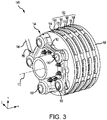
- first brake system 148 is illustrated, which does not form part of the presently claimed invention, but which may be useful for understanding it. While FIG. 3 illustrates components of first brake system 148, it is understood that second brake system 150 and/or the brake systems of right landing gear assembly 14 and/or nose landing gear assembly 16 may include the elements and functionalities as described herein with respect to first brake system 148.
- First brake system 148 includes first brake stack 152 and first piston assembly 154.
- First piston assembly 154 includes one or more pistons 160 and a piston housing (or piston manifold) 162. Pistons 160 may be mounted and/or housed within piston housing 162.
- First brake system 148 includes a pressure plate 164, an end plate 166, a plurality of rotating discs, or rotors, 168, and a plurality of non-rotating disks, or stators, 170 (collectively referred to herein as first brake stack 152).
- Rotors 168 and stators 170 are positioned in an alternating fashion between end plate 166 and pressure plate 164.
- Rotors 168 may rotate about an axis 172 and stators 170 may have little to no angular movement relative to axis 172.
- a wheel (such as first wheel 140 with brief reference to FIG. 2 ) may be coupled to rotors 168.
- Pistons 160 are configured to apply a force to pressure plate 164 in a direction towards end plate 166. As force is applied to pressure plate 164, rotors 168 and stators 170 are forced together in an axial direction between pressure plate 164 and end plate 166, thereby causing the rotational speed of rotors 168 to decrease (i.e., causing a braking effect) due to friction between rotors 168 and stators 170.
- Pistons 160 may be hydraulic pistons, also referred to as hydraulic actuators.
- changes in the hydraulic pressure within pistons 160 may cause actuation of pistons 160.
- an increase in hydraulic pressure results in an actuation of pistons 160 towards pressure plate 164, thereby increasing the force exerted on pressure plate 164.
- a decrease in hydraulic pressure results in an actuation of pistons 160 away from pressure plate 164, thereby decreasing the force exerted on pressure plate 164.
- the hydraulic pressure within pistons 160 may be controlled via a flow of hydraulic fluid to and from pistons 160.
- a hydraulic fluid source 182 may provide a hydraulic fluid 180 to first and second brake systems 148, 150.
- Hydraulic fluid source 182 may be located in the fuselage 11 and/or in wings 13 of aircraft 10, with momentary reference to FIG. 1 .
- Hydraulic fluid source 182 may be fluidly coupled to (i.e., is in fluid communication with) an upper pin inlet 184 of upper torque link pin 136 via a hydraulic fluid conduit 186.
- hydraulic fluid 180 may be provided to first and second piston assemblies 154, 158 via a series of fluidly connected upper and lower hydraulic fluid channels 200, 202 formed, respectively, through upper torque link 130 and lower torque link 132.
- Upper and lower hydraulic fluid channels 200, 202 may be fluidly connected to a hydraulic fluid conduit, or hose, 188 via, for example, lower torque link pin 138.
- Hydraulic fluid conduit 188 may be fluidly coupled between inlet 190 of piston housing 162 and a lower pin outlet 204 of lower torque link pin 138.
- Piston housing 162 may include piping (i.e., a one more hydraulic fluid conduits) fluidly coupling each of the pistons 160 to inlet 190, such that a single hydraulic fluid conduit 188 may provide hydraulic fluid 180 to each of the pistons 160.
- Piston housing 162 may include multiple hydraulic fluid inlets each having a hydraulic fluid conduit, similar to hydraulic fluid conduit 188, fluidly coupled thereto. Hydraulic fluid conduit 188 is also fluidly coupled an inlet 192 of second piston assembly 158.
- Upper torque link 130 defines an upper (or first) hydraulic fluid channel 200
- lower torque link 132 defines a lower (or second) hydraulic fluid channel 202, which is in fluid communication with upper hydraulic fluid channel 200.
- upper and lower torque links 130, 132 may each be formed using additive manufacturing.
- upper and lower torque links 130, 132 may be formed using wire arc additive manufacturing, electron beam additive manufacturing, or any other suitable additive manufacturing technique. Forming upper and lower torque links 130, 132 using additive manufacturing allows the flow paths defined by upper and lower hydraulic fluid channels 200, 202 to be formed in any desired location and having any desired geometry.
- upper and lower hydraulic fluid channels 200, 202 may be curved and/or angled and/or include bends of a varying cross section shape and size along the fluid passageway.
- hydraulic fluid 180 may flow axially, radially, and/or circumferentially through upper and lower torque links 130, 132.
- upper hydraulic fluid channel 200 may be fluidly coupled to upper torque link pin 136 and torque link pin 134.
- Lower hydraulic fluid channel 202 may be fluidly coupled to torque link pin 134 and lower torque link pin 138.
- Hydraulic fluid conduit 186 may be fluidly coupled to upper pin inlet 184 of upper torque link pin 136.
- Hydraulic fluid conduit 188 may be fluidly coupled to a lower pin outlet 204 of lower torque link pin 138.
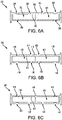
- upper torque link pin 136 defines an upper internal pin channel 206.
- upper internal pin channel 206 may be formed through, at least, a portion of upper torque link pin 136.
- Upper internal pin channel 206 provides a fluid connection between upper pin inlet 184 and an upper pin outlet 208 of upper torque link pin 136.
- hydraulic fluid conduit 186 has been removed for clarity.
- a spool may be inserted into an inner diameter of upper torque link pin 136 to distribute the hydraulic fluid.
- the spool may include fittings to connect to the hydraulic fluid source (e.g., hydraulic fluid conduit 186) and to the hydraulic fluid channel (e.g., to an inlet 216 of upper hydraulic fluid channel 200).
- an outlet groove 210 may be formed in an outer circumferential surface 212 of upper torque link pin 136.
- Outer circumferential surface 212 is generally opposite, or oriented away from, an internal surface 214 of upper torque link pin 136.
- Internal surface 214 of upper torque link pin 136 defines upper internal pin channel 206.
- Outlet groove 210 is formed at a location corresponding to upper pin outlet 208 and inlet 216 of upper hydraulic fluid channel 200.
- Outlet groove 210 allows hydraulic fluid 180 ( FIG. 2 ) to flow into upper hydraulic fluid channel 200, when inlet 216 of upper hydraulic fluid channel 200 is circumferentially offset from (i.e., not aligned with) upper pin outlet 208 of upper torque link pin 136.
- shock strut assembly 100 FIG.
- one or more O-ring seals may form a sealing interface with upper torque link pin 136 and one or more adjacent structures.
- O-ring seals 218a and 218d may be located between upper torque link pin 136 and one or more caps 220 located on opposing ends of upper internal pin channel 206.
- O-ring seals 218b and 218c may be located between upper torque link pin 136 and one or more bushings 222 located around outer circumferential surface 212.
- the number and location of O-ring seals 218 may be selected to prevent or reduce hydraulic fluid leakage.
- Torque link pin 134 defines an internal pin channel 226. Stated differently, internal pin channel 226 may be formed through, at least, a portion of torque link pin 134. Internal pin channel 226 provides a fluid connection between an inlet 228 and an outlet 230 of torque link pin 134. In various embodiments, a spool may be inserted into an inner diameter of torque link pin 134 to distribute the hydraulic fluid. The spool may include fittings to connect to an outlet 236 of upper hydraulic fluid channel 200 and to an inlet 242 of lower hydraulic fluid channel 202.
- An upper link (or first) groove 231 is formed in an outer circumferential surface 232 of torque link pin 134. Outer circumferential surface 232 is generally opposite, or oriented away from, an internal surface 234 of torque link pin 134. Internal surface 234 of torque link pin 134 defines internal pin channel 226. Upper link groove 231 is formed at a location corresponding to outlet 236 of upper hydraulic fluid channel 200 and inlet 228 of torque link pin 134. Upper link groove 231 allows hydraulic fluid 180 ( FIG. 2 ) to flow into internal pin channel 226 from upper hydraulic fluid channel 200, when outlet 236 of upper hydraulic fluid channel 200 is circumferentially offset from (i.e. not aligned with) inlet 228 of torque link pin 134. For example, as shock strut assembly 100 ( FIG.
- upper torque link 130 compresses and decompresses, upper torque link 130 rotates about torque link pin 134, thereby causing outlet 236 of upper hydraulic fluid channel 200 to rotate about outer circumferential surface 232 of torque link pin 134.
- Upper link groove 231 allows upper hydraulic fluid channel 200 to remain fluidly connected to inlet 228 of internal pin channel 226 regardless of the position of outlet 236 of upper torque link 130.
- hydraulic fluid 180 may flow from upper hydraulic fluid channel 200, into upper link groove 231, and then into internal pin channel 226.
- a lower link (or second) groove 238 may be formed in outer circumferential surface 232 of torque link pin 134.
- Lower link groove 238 is formed at a location corresponding to outlet 230 of torque link pin 134 and inlet 242 of lower hydraulic fluid channel 202.
- Lower link groove 238 allows hydraulic fluid 180 ( FIG. 2 ) to flow into lower hydraulic fluid channel 202 from internal pin channel 226, when inlet 242 of lower hydraulic fluid channel 202 is circumferentially offset from (i.e. not aligned with) outlet 230 of torque link pin 134.
- shock strut assembly 100 FIG.
- lower torque link 132 compresses and decompresses, lower torque link 132 rotates about torque link pin 134, thereby causing inlet 242 of lower hydraulic fluid channel 202 to rotate about outer circumferential surface 232 of torque link pin 134.
- Lower link groove 238 allows lower hydraulic fluid channel 202 to remain fluidly connected to outlet 230 of internal pin channel 226 regardless of the position of inlet 242 of lower torque link 132.
- hydraulic fluid 180 may flow from internal pin channel 226, into lower link groove 238, and then into lower hydraulic fluid channel 202.
- one or more O-ring seals may form a sealing interface with torque link pin 134 and one or more adjacent structures.
- the O-ring seals may be located between torque link pin 134 and one or more bushings located around outer circumferential surface 232.
- the number and location of O-ring seals may be selected to prevent or reduce hydraulic fluid leakage.
- lower torque link pin 138 defines a lower internal pin channel 246.
- lower internal pin channel 246 may be formed through, at least, a portion of lower torque link pin 138.
- Lower internal pin channel 246 provides a fluid connection between an outlet 248 of lower hydraulic fluid channel 202 and a lower pin outlet 204 of lower torque link pin 138.
- a spool may be inserted into an inner diameter of lower torque link pin 138 to distribute the hydraulic fluid.
- the spool may include fittings to connect to outlet 248 of lower hydraulic fluid channel 202 and to hydraulic fluid conduit 188.
- an inlet groove 250 may be formed in an outer circumferential surface 252 of lower torque link pin 138. Outer circumferential surface 252 is generally opposite, or oriented away from, an internal surface 254 of lower torque link pin 138. Internal surface 254 of lower torque link pin 138 defines lower internal pin channel 246. Inlet groove 250 is formed at a location corresponding to outlet 248 lower hydraulic fluid channel 202 and a lower pin inlet 256 of lower torque link pin 138. Inlet groove 250 allows hydraulic fluid 180 ( FIG. 2 ) to flow into lower internal pin channel 246, when outlet 248 of lower hydraulic fluid channel 202 is circumferentially offset from (i.e., not aligned with) lower pin inlet 256 of lower torque link pin 138.
- shock strut assembly 100 compresses and decompresses
- lower torque link 132 rotates about lower torque link pin 138, thereby causing outlet 248 to rotate about outer circumferential surface 252 of lower torque link pin 138.
- Inlet groove 250 allows lower hydraulic fluid channel 202 to remain fluidly connect to lower pin inlet 256 of lower internal pin channel 246 regardless of the position of lower torque link 132.
- hydraulic fluid 180 may flow from lower hydraulic fluid channel 202 into inlet groove 250, and then into lower internal pin channel 246. Hydraulic fluid 180 may flow from lower internal pin channel 246 to pistons 160 via hydraulic fluid conduit 188.
- one or more O-ring seals may form a sealing interface with lower torque link pin 138 and one or more adjacent structures.
- the O-ring seals may be located between lower torque link pin 138 and one or more bushings located around outer circumferential surface 252. The number and location of O-ring seals may be selected to prevent or reduce hydraulic fluid leakage.
- Additively manufacturing torque link assembly 128 including upper and lower hydraulic fluid channels 200, 202 may allow for an elimination or a reduction in the number and/or length of landing gear hydraulic hoses. Less hosing tends to reduce the number of parts associated with routing and retaining hoses, which tends to reduce an overall weight and cost of the landing gear assembly. Eliminating or reducing the length of the hydraulic hoses may decrease occurrences of contact between the hydraulic hoses and adjacent components such as tires, thereby reducing a likelihood of a burst hydraulic hose.
- Additively manufacturing upper and lower torque links 130, 132 allows the upper and lower hydraulic fluid channels 200, 202 to be formed simultaneously with upper and lower torque links 130, 132, thereby eliminating a need to drill the hydraulic fluid channels through the torque links and/or make the hydraulic fluid channels from castings.
- Additively manufactured hydraulic fluid channels tends to be advantageous over drilled passageways as additively manufactured hydraulic fluid channels may not be associated with plugs, which can result in sustained and/or residual stresses in the parent part (e.g., in upper and lower torque links 130, 132).
- shock strut assembly 100 may include torque link assembly 328 in place of torque link assembly 128.
- Torque link assembly 328 includes an upper (or first) torque link 330 and a lower (or second) torque link 332.
- Upper torque link 330 is pivotally coupled to lower torque link 332 via a torque link pin 334. Stated differently, upper torque link 330 and lower torque link 332 may rotate about torque link pin 334.
- Upper torque link 330 may be pivotally coupled to a strut cylinder or other landing gear component via an upper torque link pin 336. Stated differently, upper torque link 330 may rotate about upper torque link pin 336.
- Lower torque link 332 may be pivotally coupled to a strut piston or other landing gear component via lower torque link pin 338. Stated differently, lower torque link 332 may rotate about lower torque link pin 338.
- upper torque link 330 may define a first upper hydraulic fluid channel 340 and a second, or alternate, upper hydraulic fluid channel 342 facilitated by the additive manufacturing process.
- an inlet 344 of first upper hydraulic fluid channel 340 may be located proximate a first upper lug 346 of upper torque link 330.
- An inlet 348 of second upper hydraulic fluid channel 342 may be located proximate a second upper lug 350 of upper torque link 330.
- First and second upper lugs 346, 350 may be configured to receive upper torque link pin 336.
- An outlet 352 of first upper hydraulic fluid channel 340 may be located proximate a first lower lug 354 of upper torque link 330.
- An outlet 356 of second upper hydraulic fluid channel 342 may be located proximate a second lower lug 358 of upper torque link 330.
- First and second lower lugs 354, 358 may be configured to receive torque link pin 334.
- lower torque link 332 may define a first lower hydraulic fluid channel 360 and a second, or alternate, lower hydraulic fluid channel 362 facilitated by the additive manufacturing process.
- an inlet 364 of first lower hydraulic fluid channel 360 may be located proximate a first upper lug 366 of lower torque link 332.
- An inlet 368 of second lower hydraulic fluid channel 362 may be located proximate a second upper lug 370 of lower torque link 332.
- First and second upper lugs 366, 370 may be configured to receive torque link pin 334.
- An outlet 372 of first lower hydraulic fluid channel 360 may be located proximate a first lower lug 374 of lower torque link 332.
- An outlet 376 of second lower hydraulic fluid channel 362 may be located proximate a second lower lug 378 of lower torque link 332.
- First and second lower lugs 374, 378 may be configured to receive lower torque link pin 338.
- upper and lower torque links 330, 332 may each be formed using additive manufacturing.
- upper and lower torque links 330, 332 may be formed using wire arc additive manufacturing, electron beam additive manufacturing, or any other suitable additive manufacturing technique.
- Forming upper and lower torque links 330, 332 using additive manufacturing allows the flow paths defined by first and second upper hydraulic fluid channels 340, 342 and the flow paths defined by first and second lower hydraulic fluid channels 360, 362 to be formed in any desired location and having any desired geometry.
- hydraulic fluid channels 340, 342, 360, 362 may be curved and/or angled and/or include bends of a varying cross section shape and size along the fluid passageway.
- hydraulic fluid may flow axially, radially, and/or circumferentially through upper and lower torque links 330, 332.
- first and second upper hydraulic fluid channels 340, 342 may each be fluidly coupled to upper torque link pin 336 and torque link pin 334.
- First and second lower hydraulic fluid channels 360, 362 may be fluidly coupled to torque link pin 334 and lower torque link pin 338.
- upper torque link pin 336 defines a first upper internal pin channel 380 and a second upper internal pin channel 382.
- first upper internal pin channel 380 is fluidly isolated (i.e., not fluidly connected) from second upper internal pin channel 382.
- First upper internal pin channel 380 provides a fluid connection between a first upper pin inlet 384 of upper torque link pin 336 and a first upper pin outlet 386 of upper torque link pin 336.
- a first hydraulic fluid conduit similar to hydraulic fluid conduit 186 in FIG. 2 ) may be fluidly coupled to first upper pin inlet 384 of upper torque link pin 336 and a hydraulic fluid source.
- a first outlet groove 388 may be formed in an outer circumferential surface 390 of upper torque link pin 336. Outer circumferential surface 390 is generally opposite, or oriented away from, an internal surface 392 of upper torque link pin 336. Internal surface 392 of upper torque link pin 336 defines first and second upper internal pin channels 380, 382. First outlet groove 388 is formed at a location corresponding to first upper pin outlet 386 of upper torque link pin 336 and inlet 344 of first upper hydraulic fluid channel 340. In various embodiments, a groove may be formed in an inner circumferential surface of first upper lug 346 in place of, or in addition to, first outlet groove 388. Stated differently, first upper lug 346 may define a groove having a location that corresponds to first upper pin outlet 386 and inlet 344 of first upper hydraulic fluid channel 340.
- Second upper internal pin channel 382 provides a fluid connection between a second upper pin inlet 394 of upper torque link pin 336 and a second upper pin outlet 396 of upper torque link pin 336.
- a second hydraulic fluid conduit similar to hydraulic fluid conduit 186 in FIG. 2 ) may be fluidly coupled to second upper pin inlet 394 of upper torque link pin 336 and a hydraulic fluid source.
- first and second upper internal pin channels 380, 382 may be fluidly connects, such that upper torque link pin 336 has a single inlet, which receives hydraulic fluid from a single hydraulic fluid conduit.
- a second outlet groove 398 may be formed in outer circumferential surface 390 of upper torque link pin 336.
- Second outlet groove 398 is formed at a location corresponding to second upper pin outlet 396 of upper torque link pin 336 and inlet 348 of second upper hydraulic fluid channel 342.
- a groove may be formed in an inner circumferential surface of second upper lug 350 in place of, or in addition to, second outlet groove 398.
- second upper lug 350 may define a groove having a location that corresponds to second upper pin outlet 396 and inlet 348 of second upper hydraulic fluid channel 342.
- torque link pin 334 defines a first internal pin channel 400 and a second internal pin channel 402.
- first internal pin channel 400 is fluidly isolated from second internal pin channel 402.
- First internal pin channel 400 provides a fluid connection between a first inlet 404 of torque link pin 334 and a first outlet 406 of torque link pin 334.
- first internal pin channel 400 provides a fluid connection between first upper hydraulic fluid channel 340 and first lower hydraulic fluid channel 360.
- a first upper link groove 408 may be formed in an outer circumferential surface 410 of torque link pin 334.
- An internal surface 412 of torque link pin 334 defines first and second internal pin channels 400, 402.
- First upper link groove 408 is formed at a location corresponding to outlet 352 of first upper hydraulic fluid channel 340 and first inlet 404 of torque link pin 334.
- a groove may be formed in an inner circumferential surface of first lower lug 354 in place of, or in addition to, first upper link groove 408.
- first lower lug 354 may define a groove having a location that corresponds to outlet 352 of first upper hydraulic fluid channel 340 and first inlet 404 of torque link pin 334.
- a first lower link groove 414 may be formed in outer circumferential surface 410 of torque link pin 334.
- First lower link groove 414 is formed at a location corresponding to first outlet 406 of torque link pin 334 and inlet 364 of first lower hydraulic fluid channel 360.
- a groove may be formed in an inner circumferential surface of first upper lug 366 in place of, or in addition to, first lower link groove 414.
- first upper lug 366 may define a groove having a location that corresponds to first outlet 406 of torque link pin 334 and inlet 364 of first lower hydraulic fluid channel 360.
- Second internal pin channel 402 provides a fluid connection between a second inlet 416 of torque link pin 334 and a second outlet 418 of torque link pin 334.
- second internal pin channel 402 provides a fluid connection between second upper hydraulic fluid channel 342 and second lower hydraulic fluid channel 362.
- a second upper link groove 420 may be formed in outer circumferential surface 410 of torque link pin 334.
- Second upper link groove 420 is formed at a location corresponding to outlet 356 of second upper hydraulic fluid channel 342 and second inlet 416 of torque link pin 334.
- a groove may be formed in an inner circumferential surface of second lower lug 358 in place of, or in addition to, second upper link groove 420.
- second lower lug 358 may define a groove having a location that corresponds to outlet 356 of second upper hydraulic fluid channel 342 and second inlet 416 of torque link pin 334.
- a second lower link groove 422 may be formed in outer circumferential surface 410 of torque link pin 334.
- Second lower link groove 422 is formed at a location corresponding to second outlet 418 of torque link pin 334 and inlet 368 of second lower hydraulic fluid channel 362.
- a groove may be formed in an inner circumferential surface of second upper lug 370 in place of, or in addition to, second lower link groove 422.
- second upper lug 370 may define a groove having a location that corresponds to second outlet 418 of torque link pin 334 and inlet 368 of second lower hydraulic fluid channel 362.
- lower torque link pin 338 defines a first lower internal pin channel 430 and a second lower internal pin channel 432.
- first lower internal pin channel 430 is fluidly isolated from second lower internal pin channel 432.
- First lower internal pin channel 430 provides a fluid connection between a first lower pin inlet 434 of lower torque link pin 338 and a first lower pin outlet 436 of lower torque link pin 338.
- a first hydraulic fluid conduit similar to hydraulic fluid conduit 188 in FIG. 2 , may be fluidly coupled to first lower pin outlet 436 of lower torque link pin 338 and a hydraulic piston assembly, similar to first piston assembly 154 in FIG. 3 .
- a first inlet groove 438 may be formed in an outer circumferential surface 440 of lower torque link pin 338.
- An internal surface 441 of lower torque link pin 338 may define first and second lower internal pin channels 430, 432.
- First inlet groove 438 is formed at a location corresponding to first lower pin inlet 434 and outlet 372 of first lower hydraulic fluid channel 360.
- a groove may be formed in an inner circumferential surface of first lower lug 374 in place of, or in addition to, first inlet groove 438.
- first lower lug 374 may define a groove having a location that corresponds to first lower pin inlet 434 and outlet 372 of first lower hydraulic fluid channel 360.
- Second internal pin channel 432 provides a fluid connection between a second lower pin inlet 442 of lower torque link pin 338 and a second lower pin outlet 444 of lower torque link pin 338.
- a second hydraulic fluid conduit similar to hydraulic fluid conduit 188 in FIG. 2 may be fluidly coupled to second lower pin outlet 444 of lower torque link pin 338 and to a hydraulic piston assembly, similar to first piston assembly 154 in FIG. 3 .
- a second inlet groove 446 may be formed in outer circumferential surface 440 of lower torque link pin 338. Second inlet groove 446 is formed at a location corresponding to second lower pin inlet 442 and outlet 376 of second lower hydraulic fluid channel 362.
- a groove may be formed in an inner circumferential surface of second lower lug 378 in place of, or in addition to, second inlet groove 446.
- second lower lug 378 may define a groove having a location that corresponds to second lower pin inlet 442 and outlet 376 of second lower hydraulic fluid channel 362.
- first lower internal pin channel 430 may be fluidly connected to a first hydraulic piston assembly (e.g., first piston assembly 154 in FIG. 2 ) and second lower internal pin channel 432 may be fluidly connected to a second hydraulic piston assembly (e.g., first piston assembly 154 in FIG. 3 ) different from the first hydraulic piston assembly.
- first and second lower internal pin channels 430, 432 may be fluidly connected to the same second hydraulic piston assembly, such that second upper hydraulic fluid channel 342 and second lower hydraulic fluid channel 362 provide a redundant hydraulic fluid flow path.
- first and second lower internal pin channels 430, 432 may be fluid connected such that lower torque link pin 338 has a single outlet, which outputs hydraulic fluid to a single hydraulic fluid conduit.
- Additively manufacturing torque link assembly 328 including first and second upper hydraulic fluid channels 340, 342 and first and second lower hydraulic fluid channels 360, 362 may allow for an elimination or a reduction in the number and/or length of landing gear hydraulic hoses. Less hosing tends to reduce the number of parts associated with routing and retaining hoses, which tends to reduce an overall weight and cost of the landing gear assembly. Eliminating or reducing the length of the hydraulic hoses may decrease occurrences of contact between the hydraulic hoses and adjacent components such as tires, thereby reducing a likelihood of a burst hydraulic hose.
- Additively manufacturing upper and lower torque links 330, 332 allows the hydraulic fluid channels 340, 342, 360, 362 to be formed simultaneously with upper and lower torque links 330, 332, thereby eliminating a need to drill the hydraulic fluid channels through the torque links and/or make the hydraulic fluid channels from castings.
- Additively manufactured hydraulic fluid channels tends to be advantageous over drilled passageways as additively manufactured hydraulic fluid channels may not be associated with plugs, which can result in sustained and/or residual stresses in the parent part.
- references to "one embodiment,” “an embodiment,” “various embodiments,” etc. indicate that the embodiment described may include a particular feature, structure, or characteristic, but every embodiment may not necessarily include the particular feature, structure, or characteristic. Moreover, such phrases are not necessarily referring to the same embodiment. Further, when a particular feature, structure, or characteristic is described in connection with an embodiment, it is submitted that it is within the knowledge of one skilled in the art to affect such feature, structure, or characteristic in connection with other embodiments whether or not explicitly described. After reading the description, it will be apparent to one skilled in the relevant art(s) how to implement the disclosure in alternative embodiments.
Landscapes
- Engineering & Computer Science (AREA)
- Mechanical Engineering (AREA)
- Aviation & Aerospace Engineering (AREA)
- General Engineering & Computer Science (AREA)
- General Details Of Gearings (AREA)
- Retarders (AREA)
Claims (15)
- Fahrwerkstrebenbaugruppe (128, 138) für eine Federbeinbaugruppe einer Fahrwerksbaugruppe (12, 14), wobei die Fahrwerkstrebenbaugruppe umfasst:eine obere Fahrwerkstrebe (130), die einen ersten oberen Hydraulikflüssigkeitskanal definiert;eine untere Fahrwerkstrebe (132), die einen ersten unteren Hydraulikflüssigkeitskanal definiert; undeinen Fahrwerkstrebenstift (134), der den ersten oberen Hydraulikflüssigkeitskanal mit dem ersten unteren Hydraulikflüssigkeitskanal fluidmäßig koppelt, wobei der Fahrwerkstrebenstift (134) einen ersten inneren Stiftkanal (226) definiert und wobei der erste innere Stiftkanal eine Fluidverbindung zwischen einem Einlass (228) des Fahrwerkstrebenstifts und einem Auslass (230) des Fahrwerkstrebenstifts bereitstellt; undwobei eine äußere Umfangsfläche (232) des Fahrwerkstrebenstifts (134) eine obere Strebennut (231) definiert, wobei sich die obere Strebennut an einem Auslass (236) des ersten oberen Hydraulikflüssigkeitskanals befindet, und wobei die obere Strebennut (231) dazu konfiguriert ist, es zu ermöglichen, dass Hydraulikflüssigkeit von dem oberen Hydraulikflüssigkeitskanal in den ersten inneren Stiftkanal (226) fließen kann, wenn der Auslass (236) des oberen Hydraulikflüssigkeitskanals in Umfangsrichtung von dem Einlass (228) des Fahrwerkstrebenstifts (134) versetzt ist.
- Fahrwerkstrebenbaugruppe nach Anspruch 1, ferner umfassend einen oberen Fahrwerkstrebenstift, der durch einen oberen Ansatz der oberen Fahrwerkstrebe verläuft, wobei der obere Fahrwerkstrebenstift einen oberen inneren Stiftkanal definiert und wobei der obere innere Stiftkanal fluidmäßig mit dem ersten oberen Hydraulikflüssigkeitskanal gekoppelt ist.
- Fahrwerkstrebenbaugruppe nach Anspruch 2, ferner umfassend einen unteren Fahrwerkstrebenstift, der durch einen unteren Ansatz der unteren Fahrwerkstrebe verläuft, wobei der untere Fahrwerkstrebenstift einen unteren inneren Stiftkanal definiert und wobei der untere innere Stiftkanal fluidmäßig mit dem ersten unteren Hydraulikflüssigkeitskanal gekoppelt ist.
- Fahrwerkstrebenbaugruppe nach einem vorhergehenden Anspruch, wobei die äußere Umfangsfläche des Fahrwerkstrebenstifts eine untere Strebennut (238) definiert und wobei sich die untere Strebennut an einem Einlass (242) des ersten unteren Hydraulikflüssigkeitskanals befindet, und wobei die untere Strebennut (233) dazu konfiguriert ist, es zu ermöglichen, dass Hydraulikflüssigkeit von dem ersten inneren Stiftkanal (226) in den unteren Hydraulikflüssigkeitskanal strömt, wenn der Einlass (242) des unteren Hydraulikflüssigkeitskanals in Umfangsrichtung von dem Auslass (230) des Fahrwerkstrebenstifts (134) versetzt ist.
- Fahrwerkstrebenbaugruppe nach einem vorhergehenden Anspruch, ferner umfassend:einen zweiten oberen Hydraulikflüssigkeitskanal, der durch die obere Fahrwerkstrebe definiert ist; undeinen zweiten unteren Hydraulikflüssigkeitskanal, der durch die untere Fahrwerkstrebe definiert ist.
- Fahrwerkstrebenbaugruppe nach Anspruch 5, wobei der Fahrwerkstrebenstift den ersten inneren Stiftkanal und einen zweiten inneren Stiftkanal definiert, der von dem ersten inneren Stiftkanal fluidmäßig isoliert ist, und wobei der erste innere Stiftkanal mit dem ersten oberen Hydraulikflüssigkeitskanal und dem ersten unteren Hydraulikflüssigkeitskanal fluidmäßig gekoppelt ist und wobei der zweite innere Stiftkanal mit dem zweiten oberen Hydraulikflüssigkeitskanal und dem zweiten unteren Hydraulikflüssigkeitskanal fluidmäßig gekoppelt ist.
- Fahrwerkstrebenbaugruppe nach Anspruch 5 oder 6, ferner umfassend einen unteren Fahrwerkstrebenstift, der durch einen unteren Ansatz der unteren Fahrwerkstrebe verläuft, wobei der untere Fahrwerkstrebenstift einen ersten unteren inneren Stiftkanal und einen zweiten unteren inneren Stiftkanal definiert, der von dem ersten unteren inneren Stiftkanal fluidmäßig isoliert ist, und wobei der erste untere innere Stiftkanal mit dem ersten unteren Hydraulikflüssigkeitskanal fluidmäßig gekoppelt ist, und wobei der zweite untere innere Stiftkanal mit dem zweiten unteren Hydraulikflüssigkeitskanal fluidmäßig gekoppelt ist.
- Federbeinbaugruppe, umfassend:einen Federbeinzylinder;einen Federbeinkolben, der dazu konfiguriert ist, relativ zum Federbeinzylinder zu teleskopieren; undeine Fahrwerkstrebenbaugruppe nach einem vorhergehenden Anspruch;wobei die obere Fahrwerkstrebe mit dem Federbeinzylinder gekoppelt ist, unddie untere Fahrwerkstrebe dazu konfiguriert ist, relativ zu der oberen Fahrwerkstrebe zu schwenken.
- Federbeinbaugruppe nach Anspruch 8, ferner umfassend einen unteren Fahrwerkstrebenstift, der durch einen unteren Ansatz der unteren Fahrwerkstrebe verläuft, wobei der untere Fahrwerkstrebenstift einen unteren inneren Stiftkanal definiert und wobei der untere innere Stiftkanal fluidmäßig mit dem ersten unteren Hydraulikflüssigkeitskanal gekoppelt ist.
- Federbeinbaugruppe nach Anspruch 9, ferner umfassend eine Hydraulikflüssigkeitsleitung, die mit einem Auslass des unteren Fahrwerkstrebenstifts fluidmäßig gekoppelt ist.
- Federbeinbaugruppe nach einem der Ansprüche 8 bis 10, ferner umfassend einen oberen Fahrwerkstrebenstift, der durch einen oberen Ansatz der oberen Fahrwerkstrebe verläuft, wobei der obere Fahrwerkstrebenstift einen oberen inneren Stiftkanal definiert und wobei der obere innere Stiftkanal fluidmäßig mit dem ersten oberen Hydraulikflüssigkeitskanal gekoppelt ist, und optional ferner eine Hydraulikflüssigkeitsleitung umfassend, die mit einem Einlass des oberen Fahrwerkstrebenstifts fluidmäßig gekoppelt ist.
- Federbeinbaugruppe nach einem der Ansprüche 8 bis 11, wobei die äußere Umfangsfläche des Fahrwerkstrebenstifts eine untere Strebennut definiert und wobei die untere Strebennut sich an einem Einlass des ersten unteren Hydraulikflüssigkeitskanals befindet.
- Federbeinbaugruppe nach einem der Ansprüche 8 bis 12, wobei die obere Fahrwerkstrebe einen zweiten oberen Hydraulikflüssigkeitskanal definiert und wobei die untere Fahrwerkstrebe einen zweiten unteren Hydraulikflüssigkeitskanal definiert, und
wobei der Fahrwerkstrebenstift den ersten inneren Stiftkanal und einen zweiten inneren Stiftkanal definiert, der von dem ersten inneren Stiftkanal fluidmäßig isoliert ist, und wobei der erste innere Stiftkanal mit dem ersten oberen Hydraulikflüssigkeitskanal und dem ersten unteren Hydraulikflüssigkeitskanal fluidmäßig gekoppelt ist und wobei der zweite innere Stiftkanal mit dem zweiten oberen Hydraulikflüssigkeitskanal und dem zweiten unteren Hydraulikflüssigkeitskanal fluidmäßig gekoppelt ist. - Fahrwerksbaugruppe, umfassend:eine Federbeinbaugruppe (100);die Fahrwerkstrebenbaugruppe nach einem der Ansprüche 1-7, die mit der Federbeinbaugruppe (100) gekoppelt ist; undeinen Hydraulikkolben (154) in Fluidverbindung mit dem ersten unteren Hydraulikflüssigkeitskanal.
- Fahrwerksbaugruppe nach Anspruch 14, ferner umfassend:einen oberen Fahrwerkstrebenstift, der durch einen oberen Ansatz der oberen Fahrwerkstrebe verläuft, wobei ein oberer Stiftkanal, der durch den oberen Fahrwerkstrebenstift definiert ist, mit dem ersten oberen Hydraulikflüssigkeitskanal gekoppelt ist;eine erste Hydraulikflüssigkeitsleitung, die zwischen einem oberen Stifteinlass des oberen Fahrwerkstrebenstifts und einer Hydraulikflüssigkeitsquelle fluidmäßig gekoppelt ist;einen unteren Fahrwerkstrebenstift, der durch einen unteren Ansatz der unteren Fahrwerkstrebe verläuft, wobei ein unterer Stiftkanal, der durch den unteren Fahrwerkstrebenstift definiert ist, mit dem ersten unteren Hydraulikflüssigkeitskanal gekoppelt ist; undeine zweite Hydraulikflüssigkeitsleitung, die zwischen einem Auslass des unteren Fahrwerkstrebenstifts und einem Einlass des Hydraulikkolbens fluidmäßig gekoppelt ist.
Applications Claiming Priority (1)
| Application Number | Priority Date | Filing Date | Title |
|---|---|---|---|
| US16/409,007 US11312483B2 (en) | 2019-05-10 | 2019-05-10 | Landing gear with hydraulic fluid channels |
Publications (2)
| Publication Number | Publication Date |
|---|---|
| EP3736210A1 EP3736210A1 (de) | 2020-11-11 |
| EP3736210B1 true EP3736210B1 (de) | 2022-11-09 |
Family
ID=68847988
Family Applications (1)
| Application Number | Title | Priority Date | Filing Date |
|---|---|---|---|
| EP19214720.5A Active EP3736210B1 (de) | 2019-05-10 | 2019-12-10 | Fahrwerk mit hydraulikflüssigkeitskanälen |
Country Status (2)
| Country | Link |
|---|---|
| US (1) | US11312483B2 (de) |
| EP (1) | EP3736210B1 (de) |
Families Citing this family (3)
| Publication number | Priority date | Publication date | Assignee | Title |
|---|---|---|---|---|
| EP4259960A2 (de) * | 2020-12-14 | 2023-10-18 | Eaton Intelligent Power Limited | Additiv gefertigter hydraulischer schwenkbolzen und verfahren |
| US20240270216A1 (en) * | 2023-02-10 | 2024-08-15 | Goodrich Corporation | Integrated actuator plate for ebrake |
| PL447859A1 (pl) * | 2024-02-23 | 2025-08-25 | Marek Gąsiorowski | Przegubowe złącze panewkowo-sworzniowe i transporter modułowy zawierający wiele modułów połączonych za pomocą takich złącz |
Family Cites Families (19)
| Publication number | Priority date | Publication date | Assignee | Title |
|---|---|---|---|---|
| US2659615A (en) * | 1949-06-21 | 1953-11-17 | Lockheed Aircraft Corp | Dual hydraulic swivel joint |
| US2792998A (en) | 1952-10-23 | 1957-05-21 | Dowty Equipment Ltd | Brake system on aircraft multi-wheel bogie undercarriage |
| US6016995A (en) | 1997-08-26 | 2000-01-25 | The Boeing Company | Aircraft nose landing gear |
| US6409121B1 (en) | 2000-08-30 | 2002-06-25 | The Boeing Company | In flight autolubrication system for the mechanical members of aircraft landing gear |
| US7264398B2 (en) | 2001-08-24 | 2007-09-04 | The Boeing Company | Truck pivot joint bearing and method of lubricating |
| GB2508043B (en) | 2013-04-17 | 2015-07-22 | Messier Dowty Ltd | Dynamic bearing |
| US9140302B2 (en) | 2013-06-13 | 2015-09-22 | The Boeing Company | Joint bearing lubricant system |
| US20160199913A1 (en) | 2013-09-04 | 2016-07-14 | Bae Systems Plc | Conduit system |
| GB2521392A (en) | 2013-12-18 | 2015-06-24 | Skf Ab | Method of producing a raceway ring, inner ring or outer ring, and raceway ring |
| EP2918358B1 (de) | 2014-03-12 | 2017-06-21 | Safran Landing Systems UK Limited | Verfahren zur Herstellung eines Bauteils umfassend Fliessdrücken |
| US9958068B2 (en) | 2014-03-21 | 2018-05-01 | Goodrich Corporation | Piston housing system and apparatus |
| EP2947338B1 (de) | 2014-05-20 | 2016-11-02 | SKF Aerospace France | Kugelförmiges Gleitlager, Lageranordnung und Verfahren zur Herstellung eines solchen Lagers |
| US20160047412A1 (en) | 2014-08-12 | 2016-02-18 | The Boeing Company | Enhanced thermally conductive pivot bushing |
| US10486799B2 (en) | 2016-04-29 | 2019-11-26 | Goodrich Corporation | Rod end |
| US10933981B2 (en) | 2016-06-21 | 2021-03-02 | Goodrich Corporation | Aerodynamic noise reducing thin-skin landing gear structures and manufacturing techniques |
| US10563690B2 (en) | 2016-07-28 | 2020-02-18 | Goodrich Corporation | Thin-skin side stay beams and landing gear assemblies |
| IT201600108934A1 (it) | 2016-10-27 | 2018-04-27 | Nuovo Pignone Tecnologie Srl | Cuscinetto a pattini oscillanti e metodo per la sua fabbricazione |
| DE102016222411A1 (de) | 2016-11-15 | 2018-05-17 | Schaeffler Technologies AG & Co. KG | Schmiermittelzuführbauteil |
| CN109533296A (zh) | 2018-11-09 | 2019-03-29 | 中国直升机设计研究所 | 一种机身与起落架摇臂的连接结构 |
-
2019
- 2019-05-10 US US16/409,007 patent/US11312483B2/en active Active
- 2019-12-10 EP EP19214720.5A patent/EP3736210B1/de active Active
Also Published As
| Publication number | Publication date |
|---|---|
| US20200354045A1 (en) | 2020-11-12 |
| EP3736210A1 (de) | 2020-11-11 |
| US11312483B2 (en) | 2022-04-26 |
Similar Documents
| Publication | Publication Date | Title |
|---|---|---|
| EP3736210B1 (de) | Fahrwerk mit hydraulikflüssigkeitskanälen | |
| EP3120968B1 (de) | Verfahren zur reparatur eines flugzeugrads und von bremsenteilen | |
| CN103890417A (zh) | 具有弹性体衬套的销接头 | |
| US20100320038A1 (en) | Opposed-piston caliper body | |
| CN112041100B (zh) | 用于校准大口径管的机械式扩径机的润滑环 | |
| EP3736065B1 (de) | Additiv gefertigte schmierkanäle | |
| CN105317884B (zh) | 制作用于制动器组件的托架组件的方法 | |
| CN105179345A (zh) | 制造流体分配系统组件的方法 | |
| US2888101A (en) | Applying system for disk brake | |
| EP3453612B1 (de) | Bremsmomentlastreaktion eines flugzeugs durch die fahrwerksdrehgestellstruktur | |
| RU2682068C2 (ru) | Способ изготовления усиливающего кромочного элемента лопатки газотурбинного двигателя | |
| CN114126962A (zh) | 具有加强腹板的起落架 | |
| EP3690276A1 (de) | Generative gefertigter thermoplastischer dosierstift mit schlitzen für speicherhardware | |
| EP4368502B1 (de) | 3d-gedruckte buchse mit gedruckten fettpassagen und integrierten schmierarmaturen | |
| EP3263448B1 (de) | Verfahren zur herstellung eines lastübertragungsgelenks aus polymerverbundwerkstoff/metall für flugzeugfahrwerk | |
| US20220099225A1 (en) | Gimbal Joints for Bleed Air Systems | |
| US11530765B2 (en) | Gimbal joints for bleed air systems | |
| US5466052A (en) | A fluid connecting device | |
| US20150167764A1 (en) | Friction material engagement of a friction member | |
| EP2270352B1 (de) | Scheibenbremse | |
| US11391340B2 (en) | Non-metallic orifice plate with metallic wear insert | |
| US12498069B2 (en) | Additive manufactured hydraulic swivel bolt; and method | |
| US2762585A (en) | Steering system for aircraft undercarriages | |
| US4363383A (en) | Brake with axially expanding brake shoes | |
| EP3324090B1 (de) | Verstellpropeller mit übertragungsrohr |
Legal Events
| Date | Code | Title | Description |
|---|---|---|---|
| PUAI | Public reference made under article 153(3) epc to a published international application that has entered the european phase |
Free format text: ORIGINAL CODE: 0009012 |
|
| STAA | Information on the status of an ep patent application or granted ep patent |
Free format text: STATUS: THE APPLICATION HAS BEEN PUBLISHED |
|
| AK | Designated contracting states |
Kind code of ref document: A1 Designated state(s): AL AT BE BG CH CY CZ DE DK EE ES FI FR GB GR HR HU IE IS IT LI LT LU LV MC MK MT NL NO PL PT RO RS SE SI SK SM TR |
|
| AX | Request for extension of the european patent |
Extension state: BA ME |
|
| STAA | Information on the status of an ep patent application or granted ep patent |
Free format text: STATUS: REQUEST FOR EXAMINATION WAS MADE |
|
| 17P | Request for examination filed |
Effective date: 20210510 |
|
| RBV | Designated contracting states (corrected) |
Designated state(s): AL AT BE BG CH CY CZ DE DK EE ES FI FR GB GR HR HU IE IS IT LI LT LU LV MC MK MT NL NO PL PT RO RS SE SI SK SM TR |
|
| GRAP | Despatch of communication of intention to grant a patent |
Free format text: ORIGINAL CODE: EPIDOSNIGR1 |
|
| STAA | Information on the status of an ep patent application or granted ep patent |
Free format text: STATUS: GRANT OF PATENT IS INTENDED |
|
| RIC1 | Information provided on ipc code assigned before grant |
Ipc: B64C 25/34 20060101ALN20220425BHEP Ipc: F16L 27/00 20060101ALI20220425BHEP Ipc: F16L 39/04 20060101ALI20220425BHEP Ipc: F16L 27/093 20060101ALI20220425BHEP Ipc: B64C 25/42 20060101ALI20220425BHEP Ipc: B64C 25/60 20060101AFI20220425BHEP |
|
| INTG | Intention to grant announced |
Effective date: 20220525 |
|
| RIN1 | Information on inventor provided before grant (corrected) |
Inventor name: LEONG, MARK S. |
|
| GRAS | Grant fee paid |
Free format text: ORIGINAL CODE: EPIDOSNIGR3 |
|
| GRAA | (expected) grant |
Free format text: ORIGINAL CODE: 0009210 |
|
| STAA | Information on the status of an ep patent application or granted ep patent |
Free format text: STATUS: THE PATENT HAS BEEN GRANTED |
|
| AK | Designated contracting states |
Kind code of ref document: B1 Designated state(s): AL AT BE BG CH CY CZ DE DK EE ES FI FR GB GR HR HU IE IS IT LI LT LU LV MC MK MT NL NO PL PT RO RS SE SI SK SM TR |
|
| REG | Reference to a national code |
Ref country code: GB Ref legal event code: FG4D |
|
| REG | Reference to a national code |
Ref country code: CH Ref legal event code: EP Ref country code: AT Ref legal event code: REF Ref document number: 1530196 Country of ref document: AT Kind code of ref document: T Effective date: 20221115 |
|
| REG | Reference to a national code |
Ref country code: DE Ref legal event code: R096 Ref document number: 602019021660 Country of ref document: DE |
|
| REG | Reference to a national code |
Ref country code: IE Ref legal event code: FG4D |
|
| REG | Reference to a national code |
Ref country code: LT Ref legal event code: MG9D |
|
| REG | Reference to a national code |
Ref country code: NL Ref legal event code: MP Effective date: 20221109 |
|
| REG | Reference to a national code |
Ref country code: AT Ref legal event code: MK05 Ref document number: 1530196 Country of ref document: AT Kind code of ref document: T Effective date: 20221109 |
|
| PG25 | Lapsed in a contracting state [announced via postgrant information from national office to epo] |
Ref country code: SE Free format text: LAPSE BECAUSE OF FAILURE TO SUBMIT A TRANSLATION OF THE DESCRIPTION OR TO PAY THE FEE WITHIN THE PRESCRIBED TIME-LIMIT Effective date: 20221109 Ref country code: PT Free format text: LAPSE BECAUSE OF FAILURE TO SUBMIT A TRANSLATION OF THE DESCRIPTION OR TO PAY THE FEE WITHIN THE PRESCRIBED TIME-LIMIT Effective date: 20230309 Ref country code: NO Free format text: LAPSE BECAUSE OF FAILURE TO SUBMIT A TRANSLATION OF THE DESCRIPTION OR TO PAY THE FEE WITHIN THE PRESCRIBED TIME-LIMIT Effective date: 20230209 Ref country code: LT Free format text: LAPSE BECAUSE OF FAILURE TO SUBMIT A TRANSLATION OF THE DESCRIPTION OR TO PAY THE FEE WITHIN THE PRESCRIBED TIME-LIMIT Effective date: 20221109 Ref country code: FI Free format text: LAPSE BECAUSE OF FAILURE TO SUBMIT A TRANSLATION OF THE DESCRIPTION OR TO PAY THE FEE WITHIN THE PRESCRIBED TIME-LIMIT Effective date: 20221109 Ref country code: ES Free format text: LAPSE BECAUSE OF FAILURE TO SUBMIT A TRANSLATION OF THE DESCRIPTION OR TO PAY THE FEE WITHIN THE PRESCRIBED TIME-LIMIT Effective date: 20221109 Ref country code: AT Free format text: LAPSE BECAUSE OF FAILURE TO SUBMIT A TRANSLATION OF THE DESCRIPTION OR TO PAY THE FEE WITHIN THE PRESCRIBED TIME-LIMIT Effective date: 20221109 |
|
| PG25 | Lapsed in a contracting state [announced via postgrant information from national office to epo] |
Ref country code: RS Free format text: LAPSE BECAUSE OF FAILURE TO SUBMIT A TRANSLATION OF THE DESCRIPTION OR TO PAY THE FEE WITHIN THE PRESCRIBED TIME-LIMIT Effective date: 20221109 Ref country code: PL Free format text: LAPSE BECAUSE OF FAILURE TO SUBMIT A TRANSLATION OF THE DESCRIPTION OR TO PAY THE FEE WITHIN THE PRESCRIBED TIME-LIMIT Effective date: 20221109 Ref country code: LV Free format text: LAPSE BECAUSE OF FAILURE TO SUBMIT A TRANSLATION OF THE DESCRIPTION OR TO PAY THE FEE WITHIN THE PRESCRIBED TIME-LIMIT Effective date: 20221109 Ref country code: IS Free format text: LAPSE BECAUSE OF FAILURE TO SUBMIT A TRANSLATION OF THE DESCRIPTION OR TO PAY THE FEE WITHIN THE PRESCRIBED TIME-LIMIT Effective date: 20230309 Ref country code: HR Free format text: LAPSE BECAUSE OF FAILURE TO SUBMIT A TRANSLATION OF THE DESCRIPTION OR TO PAY THE FEE WITHIN THE PRESCRIBED TIME-LIMIT Effective date: 20221109 Ref country code: GR Free format text: LAPSE BECAUSE OF FAILURE TO SUBMIT A TRANSLATION OF THE DESCRIPTION OR TO PAY THE FEE WITHIN THE PRESCRIBED TIME-LIMIT Effective date: 20230210 |
|
| P01 | Opt-out of the competence of the unified patent court (upc) registered |
Effective date: 20230522 |
|
| PG25 | Lapsed in a contracting state [announced via postgrant information from national office to epo] |
Ref country code: NL Free format text: LAPSE BECAUSE OF FAILURE TO SUBMIT A TRANSLATION OF THE DESCRIPTION OR TO PAY THE FEE WITHIN THE PRESCRIBED TIME-LIMIT Effective date: 20221109 |
|
| PG25 | Lapsed in a contracting state [announced via postgrant information from national office to epo] |
Ref country code: RO Free format text: LAPSE BECAUSE OF FAILURE TO SUBMIT A TRANSLATION OF THE DESCRIPTION OR TO PAY THE FEE WITHIN THE PRESCRIBED TIME-LIMIT Effective date: 20221109 Ref country code: EE Free format text: LAPSE BECAUSE OF FAILURE TO SUBMIT A TRANSLATION OF THE DESCRIPTION OR TO PAY THE FEE WITHIN THE PRESCRIBED TIME-LIMIT Effective date: 20221109 Ref country code: DK Free format text: LAPSE BECAUSE OF FAILURE TO SUBMIT A TRANSLATION OF THE DESCRIPTION OR TO PAY THE FEE WITHIN THE PRESCRIBED TIME-LIMIT Effective date: 20221109 Ref country code: CZ Free format text: LAPSE BECAUSE OF FAILURE TO SUBMIT A TRANSLATION OF THE DESCRIPTION OR TO PAY THE FEE WITHIN THE PRESCRIBED TIME-LIMIT Effective date: 20221109 Ref country code: SM Free format text: LAPSE BECAUSE OF FAILURE TO SUBMIT A TRANSLATION OF THE DESCRIPTION OR TO PAY THE FEE WITHIN THE PRESCRIBED TIME-LIMIT Effective date: 20221109 |
|
| REG | Reference to a national code |
Ref country code: CH Ref legal event code: PL |
|
| REG | Reference to a national code |
Ref country code: DE Ref legal event code: R097 Ref document number: 602019021660 Country of ref document: DE |
|
| REG | Reference to a national code |
Ref country code: BE Ref legal event code: MM Effective date: 20221231 |
|
| PG25 | Lapsed in a contracting state [announced via postgrant information from national office to epo] |
Ref country code: SK Free format text: LAPSE BECAUSE OF FAILURE TO SUBMIT A TRANSLATION OF THE DESCRIPTION OR TO PAY THE FEE WITHIN THE PRESCRIBED TIME-LIMIT Effective date: 20221109 Ref country code: LU Free format text: LAPSE BECAUSE OF NON-PAYMENT OF DUE FEES Effective date: 20221210 Ref country code: AL Free format text: LAPSE BECAUSE OF FAILURE TO SUBMIT A TRANSLATION OF THE DESCRIPTION OR TO PAY THE FEE WITHIN THE PRESCRIBED TIME-LIMIT Effective date: 20221109 |
|
| PLBE | No opposition filed within time limit |
Free format text: ORIGINAL CODE: 0009261 |
|
| STAA | Information on the status of an ep patent application or granted ep patent |
Free format text: STATUS: NO OPPOSITION FILED WITHIN TIME LIMIT |
|
| 26N | No opposition filed |
Effective date: 20230810 |
|
| PG25 | Lapsed in a contracting state [announced via postgrant information from national office to epo] |
Ref country code: LI Free format text: LAPSE BECAUSE OF NON-PAYMENT OF DUE FEES Effective date: 20221231 Ref country code: IE Free format text: LAPSE BECAUSE OF NON-PAYMENT OF DUE FEES Effective date: 20221210 Ref country code: CH Free format text: LAPSE BECAUSE OF NON-PAYMENT OF DUE FEES Effective date: 20221231 |
|
| PG25 | Lapsed in a contracting state [announced via postgrant information from national office to epo] |
Ref country code: SI Free format text: LAPSE BECAUSE OF FAILURE TO SUBMIT A TRANSLATION OF THE DESCRIPTION OR TO PAY THE FEE WITHIN THE PRESCRIBED TIME-LIMIT Effective date: 20221109 Ref country code: BE Free format text: LAPSE BECAUSE OF NON-PAYMENT OF DUE FEES Effective date: 20221231 |
|
| PG25 | Lapsed in a contracting state [announced via postgrant information from national office to epo] |
Ref country code: CY Free format text: LAPSE BECAUSE OF FAILURE TO SUBMIT A TRANSLATION OF THE DESCRIPTION OR TO PAY THE FEE WITHIN THE PRESCRIBED TIME-LIMIT Effective date: 20221109 |
|
| PG25 | Lapsed in a contracting state [announced via postgrant information from national office to epo] |
Ref country code: MK Free format text: LAPSE BECAUSE OF FAILURE TO SUBMIT A TRANSLATION OF THE DESCRIPTION OR TO PAY THE FEE WITHIN THE PRESCRIBED TIME-LIMIT Effective date: 20221109 Ref country code: IT Free format text: LAPSE BECAUSE OF FAILURE TO SUBMIT A TRANSLATION OF THE DESCRIPTION OR TO PAY THE FEE WITHIN THE PRESCRIBED TIME-LIMIT Effective date: 20221109 Ref country code: HU Free format text: LAPSE BECAUSE OF FAILURE TO SUBMIT A TRANSLATION OF THE DESCRIPTION OR TO PAY THE FEE WITHIN THE PRESCRIBED TIME-LIMIT; INVALID AB INITIO Effective date: 20191210 |
|
| PG25 | Lapsed in a contracting state [announced via postgrant information from national office to epo] |
Ref country code: MC Free format text: LAPSE BECAUSE OF FAILURE TO SUBMIT A TRANSLATION OF THE DESCRIPTION OR TO PAY THE FEE WITHIN THE PRESCRIBED TIME-LIMIT Effective date: 20221109 |
|
| PG25 | Lapsed in a contracting state [announced via postgrant information from national office to epo] |
Ref country code: MC Free format text: LAPSE BECAUSE OF FAILURE TO SUBMIT A TRANSLATION OF THE DESCRIPTION OR TO PAY THE FEE WITHIN THE PRESCRIBED TIME-LIMIT Effective date: 20221109 |
|
| PG25 | Lapsed in a contracting state [announced via postgrant information from national office to epo] |
Ref country code: BG Free format text: LAPSE BECAUSE OF FAILURE TO SUBMIT A TRANSLATION OF THE DESCRIPTION OR TO PAY THE FEE WITHIN THE PRESCRIBED TIME-LIMIT Effective date: 20221109 |
|
| GBPC | Gb: european patent ceased through non-payment of renewal fee |
Effective date: 20231210 |
|
| PG25 | Lapsed in a contracting state [announced via postgrant information from national office to epo] |
Ref country code: MT Free format text: LAPSE BECAUSE OF FAILURE TO SUBMIT A TRANSLATION OF THE DESCRIPTION OR TO PAY THE FEE WITHIN THE PRESCRIBED TIME-LIMIT Effective date: 20221109 |
|
| PG25 | Lapsed in a contracting state [announced via postgrant information from national office to epo] |
Ref country code: GB Free format text: LAPSE BECAUSE OF NON-PAYMENT OF DUE FEES Effective date: 20231210 |
|
| PG25 | Lapsed in a contracting state [announced via postgrant information from national office to epo] |
Ref country code: GB Free format text: LAPSE BECAUSE OF NON-PAYMENT OF DUE FEES Effective date: 20231210 |
|
| PG25 | Lapsed in a contracting state [announced via postgrant information from national office to epo] |
Ref country code: TR Free format text: LAPSE BECAUSE OF FAILURE TO SUBMIT A TRANSLATION OF THE DESCRIPTION OR TO PAY THE FEE WITHIN THE PRESCRIBED TIME-LIMIT Effective date: 20221109 |
|
| PGFP | Annual fee paid to national office [announced via postgrant information from national office to epo] |
Ref country code: DE Payment date: 20251126 Year of fee payment: 7 |
|
| PGFP | Annual fee paid to national office [announced via postgrant information from national office to epo] |
Ref country code: FR Payment date: 20251120 Year of fee payment: 7 |