EP3120968B1 - Verfahren zur reparatur eines flugzeugrads und von bremsenteilen - Google Patents
Verfahren zur reparatur eines flugzeugrads und von bremsenteilen Download PDFInfo
- Publication number
- EP3120968B1 EP3120968B1 EP16180372.1A EP16180372A EP3120968B1 EP 3120968 B1 EP3120968 B1 EP 3120968B1 EP 16180372 A EP16180372 A EP 16180372A EP 3120968 B1 EP3120968 B1 EP 3120968B1
- Authority
- EP
- European Patent Office
- Prior art keywords
- bore
- aircraft
- wheel
- various embodiments
- additive manufacturing
- Prior art date
- Legal status (The legal status is an assumption and is not a legal conclusion. Google has not performed a legal analysis and makes no representation as to the accuracy of the status listed.)
- Active
Links
- 0 C[C@](CC[N+]1(CC1)[O-])(CC1CCCCCCCCC*(C[N+]([O-])=O)CCCCC2C1)C2*=C Chemical compound C[C@](CC[N+]1(CC1)[O-])(CC1CCCCCCCCC*(C[N+]([O-])=O)CCCCC2C1)C2*=C 0.000 description 2
Images


Classifications
-
- C—CHEMISTRY; METALLURGY
- C23—COATING METALLIC MATERIAL; COATING MATERIAL WITH METALLIC MATERIAL; CHEMICAL SURFACE TREATMENT; DIFFUSION TREATMENT OF METALLIC MATERIAL; COATING BY VACUUM EVAPORATION, BY SPUTTERING, BY ION IMPLANTATION OR BY CHEMICAL VAPOUR DEPOSITION, IN GENERAL; INHIBITING CORROSION OF METALLIC MATERIAL OR INCRUSTATION IN GENERAL
- C23C—COATING METALLIC MATERIAL; COATING MATERIAL WITH METALLIC MATERIAL; SURFACE TREATMENT OF METALLIC MATERIAL BY DIFFUSION INTO THE SURFACE, BY CHEMICAL CONVERSION OR SUBSTITUTION; COATING BY VACUUM EVAPORATION, BY SPUTTERING, BY ION IMPLANTATION OR BY CHEMICAL VAPOUR DEPOSITION, IN GENERAL
- C23C24/00—Coating starting from inorganic powder
- C23C24/02—Coating starting from inorganic powder by application of pressure only
- C23C24/04—Impact or kinetic deposition of particles
-
- B—PERFORMING OPERATIONS; TRANSPORTING
- B22—CASTING; POWDER METALLURGY
- B22F—WORKING METALLIC POWDER; MANUFACTURE OF ARTICLES FROM METALLIC POWDER; MAKING METALLIC POWDER; APPARATUS OR DEVICES SPECIALLY ADAPTED FOR METALLIC POWDER
- B22F10/00—Additive manufacturing of workpieces or articles from metallic powder
- B22F10/20—Direct sintering or melting
- B22F10/25—Direct deposition of metal particles, e.g. direct metal deposition [DMD] or laser engineered net shaping [LENS]
-
- B—PERFORMING OPERATIONS; TRANSPORTING
- B22—CASTING; POWDER METALLURGY
- B22F—WORKING METALLIC POWDER; MANUFACTURE OF ARTICLES FROM METALLIC POWDER; MAKING METALLIC POWDER; APPARATUS OR DEVICES SPECIALLY ADAPTED FOR METALLIC POWDER
- B22F10/00—Additive manufacturing of workpieces or articles from metallic powder
- B22F10/20—Direct sintering or melting
- B22F10/28—Powder bed fusion, e.g. selective laser melting [SLM] or electron beam melting [EBM]
-
- B—PERFORMING OPERATIONS; TRANSPORTING
- B22—CASTING; POWDER METALLURGY
- B22F—WORKING METALLIC POWDER; MANUFACTURE OF ARTICLES FROM METALLIC POWDER; MAKING METALLIC POWDER; APPARATUS OR DEVICES SPECIALLY ADAPTED FOR METALLIC POWDER
- B22F10/00—Additive manufacturing of workpieces or articles from metallic powder
- B22F10/60—Treatment of workpieces or articles after build-up
- B22F10/66—Treatment of workpieces or articles after build-up by mechanical means
-
- B—PERFORMING OPERATIONS; TRANSPORTING
- B22—CASTING; POWDER METALLURGY
- B22F—WORKING METALLIC POWDER; MANUFACTURE OF ARTICLES FROM METALLIC POWDER; MAKING METALLIC POWDER; APPARATUS OR DEVICES SPECIALLY ADAPTED FOR METALLIC POWDER
- B22F7/00—Manufacture of composite layers, workpieces, or articles, comprising metallic powder, by sintering the powder, with or without compacting wherein at least one part is obtained by sintering or compression
- B22F7/06—Manufacture of composite layers, workpieces, or articles, comprising metallic powder, by sintering the powder, with or without compacting wherein at least one part is obtained by sintering or compression of composite workpieces or articles from parts, e.g. to form tipped tools
-
- B—PERFORMING OPERATIONS; TRANSPORTING
- B23—MACHINE TOOLS; METAL-WORKING NOT OTHERWISE PROVIDED FOR
- B23P—METAL-WORKING NOT OTHERWISE PROVIDED FOR; COMBINED OPERATIONS; UNIVERSAL MACHINE TOOLS
- B23P6/00—Restoring or reconditioning objects
-
- B—PERFORMING OPERATIONS; TRANSPORTING
- B33—ADDITIVE MANUFACTURING TECHNOLOGY
- B33Y—ADDITIVE MANUFACTURING, i.e. MANUFACTURING OF THREE-DIMENSIONAL [3D] OBJECTS BY ADDITIVE DEPOSITION, ADDITIVE AGGLOMERATION OR ADDITIVE LAYERING, e.g. BY 3D PRINTING, STEREOLITHOGRAPHY OR SELECTIVE LASER SINTERING
- B33Y10/00—Processes of additive manufacturing
-
- B—PERFORMING OPERATIONS; TRANSPORTING
- B33—ADDITIVE MANUFACTURING TECHNOLOGY
- B33Y—ADDITIVE MANUFACTURING, i.e. MANUFACTURING OF THREE-DIMENSIONAL [3D] OBJECTS BY ADDITIVE DEPOSITION, ADDITIVE AGGLOMERATION OR ADDITIVE LAYERING, e.g. BY 3D PRINTING, STEREOLITHOGRAPHY OR SELECTIVE LASER SINTERING
- B33Y80/00—Products made by additive manufacturing
-
- B—PERFORMING OPERATIONS; TRANSPORTING
- B60—VEHICLES IN GENERAL
- B60T—VEHICLE BRAKE CONTROL SYSTEMS OR PARTS THEREOF; BRAKE CONTROL SYSTEMS OR PARTS THEREOF, IN GENERAL; ARRANGEMENT OF BRAKING ELEMENTS ON VEHICLES IN GENERAL; PORTABLE DEVICES FOR PREVENTING UNWANTED MOVEMENT OF VEHICLES; VEHICLE MODIFICATIONS TO FACILITATE COOLING OF BRAKES
- B60T8/00—Arrangements for adjusting wheel-braking force to meet varying vehicular or ground-surface conditions, e.g. limiting or varying distribution of braking force
- B60T8/17—Using electrical or electronic regulation means to control braking
- B60T8/1701—Braking or traction control means specially adapted for particular types of vehicles
- B60T8/1703—Braking or traction control means specially adapted for particular types of vehicles for aircrafts
-
- B—PERFORMING OPERATIONS; TRANSPORTING
- B64—AIRCRAFT; AVIATION; COSMONAUTICS
- B64C—AEROPLANES; HELICOPTERS
- B64C25/00—Alighting gear
- B64C25/32—Alighting gear characterised by elements which contact the ground or similar surface
- B64C25/34—Alighting gear characterised by elements which contact the ground or similar surface wheeled type, e.g. multi-wheeled bogies
- B64C25/36—Arrangements or adaptations of wheels, tyres or axles in general
-
- B—PERFORMING OPERATIONS; TRANSPORTING
- B64—AIRCRAFT; AVIATION; COSMONAUTICS
- B64C—AEROPLANES; HELICOPTERS
- B64C25/00—Alighting gear
- B64C25/32—Alighting gear characterised by elements which contact the ground or similar surface
- B64C25/42—Arrangement or adaptation of brakes
- B64C25/44—Actuating mechanisms
-
- B—PERFORMING OPERATIONS; TRANSPORTING
- B64—AIRCRAFT; AVIATION; COSMONAUTICS
- B64F—GROUND OR AIRCRAFT-CARRIER-DECK INSTALLATIONS SPECIALLY ADAPTED FOR USE IN CONNECTION WITH AIRCRAFT; DESIGNING, MANUFACTURING, ASSEMBLING, CLEANING, MAINTAINING OR REPAIRING AIRCRAFT, NOT OTHERWISE PROVIDED FOR; HANDLING, TRANSPORTING, TESTING OR INSPECTING AIRCRAFT COMPONENTS, NOT OTHERWISE PROVIDED FOR
- B64F5/00—Designing, manufacturing, assembling, cleaning, maintaining or repairing aircraft, not otherwise provided for; Handling, transporting, testing or inspecting aircraft components, not otherwise provided for
- B64F5/40—Maintaining or repairing aircraft
-
- C—CHEMISTRY; METALLURGY
- C23—COATING METALLIC MATERIAL; COATING MATERIAL WITH METALLIC MATERIAL; CHEMICAL SURFACE TREATMENT; DIFFUSION TREATMENT OF METALLIC MATERIAL; COATING BY VACUUM EVAPORATION, BY SPUTTERING, BY ION IMPLANTATION OR BY CHEMICAL VAPOUR DEPOSITION, IN GENERAL; INHIBITING CORROSION OF METALLIC MATERIAL OR INCRUSTATION IN GENERAL
- C23C—COATING METALLIC MATERIAL; COATING MATERIAL WITH METALLIC MATERIAL; SURFACE TREATMENT OF METALLIC MATERIAL BY DIFFUSION INTO THE SURFACE, BY CHEMICAL CONVERSION OR SUBSTITUTION; COATING BY VACUUM EVAPORATION, BY SPUTTERING, BY ION IMPLANTATION OR BY CHEMICAL VAPOUR DEPOSITION, IN GENERAL
- C23C24/00—Coating starting from inorganic powder
- C23C24/08—Coating starting from inorganic powder by application of heat or pressure and heat
- C23C24/10—Coating starting from inorganic powder by application of heat or pressure and heat with intermediate formation of a liquid phase in the layer
-
- F—MECHANICAL ENGINEERING; LIGHTING; HEATING; WEAPONS; BLASTING
- F01—MACHINES OR ENGINES IN GENERAL; ENGINE PLANTS IN GENERAL; STEAM ENGINES
- F01D—NON-POSITIVE DISPLACEMENT MACHINES OR ENGINES, e.g. STEAM TURBINES
- F01D5/00—Blades; Blade-carrying members; Heating, heat-insulating, cooling or antivibration means on the blades or the members
- F01D5/005—Repairing methods or devices
-
- B—PERFORMING OPERATIONS; TRANSPORTING
- B22—CASTING; POWDER METALLURGY
- B22F—WORKING METALLIC POWDER; MANUFACTURE OF ARTICLES FROM METALLIC POWDER; MAKING METALLIC POWDER; APPARATUS OR DEVICES SPECIALLY ADAPTED FOR METALLIC POWDER
- B22F7/00—Manufacture of composite layers, workpieces, or articles, comprising metallic powder, by sintering the powder, with or without compacting wherein at least one part is obtained by sintering or compression
- B22F7/06—Manufacture of composite layers, workpieces, or articles, comprising metallic powder, by sintering the powder, with or without compacting wherein at least one part is obtained by sintering or compression of composite workpieces or articles from parts, e.g. to form tipped tools
- B22F7/062—Manufacture of composite layers, workpieces, or articles, comprising metallic powder, by sintering the powder, with or without compacting wherein at least one part is obtained by sintering or compression of composite workpieces or articles from parts, e.g. to form tipped tools involving the connection or repairing of preformed parts
- B22F2007/068—Manufacture of composite layers, workpieces, or articles, comprising metallic powder, by sintering the powder, with or without compacting wherein at least one part is obtained by sintering or compression of composite workpieces or articles from parts, e.g. to form tipped tools involving the connection or repairing of preformed parts repairing articles
-
- B—PERFORMING OPERATIONS; TRANSPORTING
- B22—CASTING; POWDER METALLURGY
- B22F—WORKING METALLIC POWDER; MANUFACTURE OF ARTICLES FROM METALLIC POWDER; MAKING METALLIC POWDER; APPARATUS OR DEVICES SPECIALLY ADAPTED FOR METALLIC POWDER
- B22F2998/00—Supplementary information concerning processes or compositions relating to powder metallurgy
- B22F2998/10—Processes characterised by the sequence of their steps
-
- B—PERFORMING OPERATIONS; TRANSPORTING
- B22—CASTING; POWDER METALLURGY
- B22F—WORKING METALLIC POWDER; MANUFACTURE OF ARTICLES FROM METALLIC POWDER; MAKING METALLIC POWDER; APPARATUS OR DEVICES SPECIALLY ADAPTED FOR METALLIC POWDER
- B22F2999/00—Aspects linked to processes or compositions used in powder metallurgy
-
- B—PERFORMING OPERATIONS; TRANSPORTING
- B22—CASTING; POWDER METALLURGY
- B22F—WORKING METALLIC POWDER; MANUFACTURE OF ARTICLES FROM METALLIC POWDER; MAKING METALLIC POWDER; APPARATUS OR DEVICES SPECIALLY ADAPTED FOR METALLIC POWDER
- B22F7/00—Manufacture of composite layers, workpieces, or articles, comprising metallic powder, by sintering the powder, with or without compacting wherein at least one part is obtained by sintering or compression
- B22F7/06—Manufacture of composite layers, workpieces, or articles, comprising metallic powder, by sintering the powder, with or without compacting wherein at least one part is obtained by sintering or compression of composite workpieces or articles from parts, e.g. to form tipped tools
- B22F7/08—Manufacture of composite layers, workpieces, or articles, comprising metallic powder, by sintering the powder, with or without compacting wherein at least one part is obtained by sintering or compression of composite workpieces or articles from parts, e.g. to form tipped tools with one or more parts not made from powder
-
- B—PERFORMING OPERATIONS; TRANSPORTING
- B23—MACHINE TOOLS; METAL-WORKING NOT OTHERWISE PROVIDED FOR
- B23P—METAL-WORKING NOT OTHERWISE PROVIDED FOR; COMBINED OPERATIONS; UNIVERSAL MACHINE TOOLS
- B23P2700/00—Indexing scheme relating to the articles being treated, e.g. manufactured, repaired, assembled, connected or other operations covered in the subgroups
- B23P2700/01—Aircraft parts
-
- Y—GENERAL TAGGING OF NEW TECHNOLOGICAL DEVELOPMENTS; GENERAL TAGGING OF CROSS-SECTIONAL TECHNOLOGIES SPANNING OVER SEVERAL SECTIONS OF THE IPC; TECHNICAL SUBJECTS COVERED BY FORMER USPC CROSS-REFERENCE ART COLLECTIONS [XRACs] AND DIGESTS
- Y02—TECHNOLOGIES OR APPLICATIONS FOR MITIGATION OR ADAPTATION AGAINST CLIMATE CHANGE
- Y02P—CLIMATE CHANGE MITIGATION TECHNOLOGIES IN THE PRODUCTION OR PROCESSING OF GOODS
- Y02P10/00—Technologies related to metal processing
- Y02P10/25—Process efficiency
Definitions
- the present disclosure relates generally to the field of materials technology, and more specifically to systems and methods for aircraft wheel and brake components repair.
- aircraft wheel and brake assemblies comprise rotating and stationary disks which stop the aircraft in response to being compressed together. Wheel and brake assemblies may experience substantial loading and stress during operation. Thus, the structural integrity of wheel and brake components is important for successful operation.
- aircraft wheels may comprise two halves which may comprise mating surfaces that, when coupled together, benefit from precise alignment and sealing. Aircraft wheels may provide a sealing surface which, along with a tire, may define a void which houses a compressed gas such as nitrogen and/or air. Thus, the sealing action of the wheel and tire assembly is important to acceptable operation.
- aircraft wheels may include bearing bore surfaces as well as various other surfaces which may experience wear or corrosion over time. Thus, after extended use of aircraft wheel and brake assemblies, repair may be needed from time to time.
- US2013/0209826A1 describes a method of repairing components having damaged internally threaded openings.
- US 2001/020734 A1 describes a method of repairing metallic components.
- WO 2013/184401 A1 describes a method of working an airfoil using elevated temperature CMT welding.
- EP 2873620 A1 describes a repair method for fuselage components of an aircraft or spacecraft.
- US 2006/045785 A1 describes a method for repairing titanium alloy components.
- EP 1674595 A2 describes structural repair using cold sprayed aluminum material.
- EP 2778256 A1 describes methods utilizing cold spray techniques for repairing and protecting rotary components or aviation propulsion systems.
- US5638591A describes a method for restoring a wheel beadseat.
- WO2015/069588A1 describes a method of superalloy material deposition with interlayer material removal.
- any reference to singular includes plural embodiments, and any reference to more than one component or step may include a singular embodiment or step.
- any reference to attached, fixed, connected or the like may include permanent, removable, temporary, partial, full and/or any other possible attachment option.
- any reference to without contact (or similar phrases) may also include reduced contact or minimal contact.
- additive manufacturing encompasses any method or process whereby a three-dimensional object is produced by creation of a substrate or addition of material to an object, such as by addition of successive layers of a material to an object to produce a manufactured product having an increased mass or bulk at the end of the additive manufacturing process than the beginning of the process.
- traditional manufacturing e.g., forms of subtractive manufacturing
- material removal or subtractive processes such as cutting, lathing, drilling, grinding, and/or the like, to produce a final manufactured object that has a decreased mass or bulk relative to the starting workpiece.
- additive manufacturing should not be construed to encompass fabrication or joining of previously formed objects.
- additive manufacturing technologies are commercially available. Such technologies include, for example, fused deposition modeling, polyjet 3D printing, electron beam freeform fabrication, direct metal laser sintering, electron-beam melting, selective laser melting, selective heat sintering, selective laser sintering, stereolithography, multiphoton photopolymerization, digital light processing, and cold spray. These technologies may use a variety of materials as substrates for an additive manufacturing process, including various plastics and polymers, metals and metal alloys, ceramic materials, metal clays, organic materials, and the like. Any method of additive manufacturing and associated compatible materials, whether presently available or yet to be developed, is intended to be included within the scope of the present disclosure. As used herein, the term “additive manufacturing” and “additive repair” may be used interchangeably.
- Aircraft may comprise one or more types of aircraft wheel and brake assemblies.
- an aircraft wheel and brake assembly may comprise a wheel mounted to a non-rotatable wheel support for rotation, and a brake disk stack.
- the brake stack may have front and rear axial ends and alternating rotor and stator disks mounted with respect to the wheel support and wheel for relative axial movement.
- Each rotor disk may be coupled to the wheel for rotation therewith and each stator disk is coupled to the wheel support, preventing rotation.
- a torque plate may be located at the rear end of the disk pack and a piston housing may be located at the front end.
- the piston housing may house one or more pistons that extend to compress the brake disk stack against the torque plate, or the brake disk stack may be compressed by other means. Torque is taken out by the stator disks through a static torque plate or the like. More specifically, the stators may be coupled to a torque plate via notches on the stator inner diameter (ID) which accept splines on the torque plate barrel outer diameter (OD). The torque plate may transfer a load to the piston housing which is coupled to the aircraft landing gear. Thus, a load path may exist from the ground, through a tire, to the wheel, to the rotors, to the stators, to the torque plate, through the piston housing, and into the landing gear. Accordingly, any part included in a wheel and brake assembly may be referred to herein as a "wheel and brake part".
- ⁇ may refer to corrosion, cracks, dents, bends and otherwise deformed areas. Other types of damage are possible.
- Various components may incur damage that may benefit from repair to restore one or more of geometric and structural properties.
- a thermal spray technique may be used to restore the geometry of a component.
- thermal spray techniques may not restore structural properties of a component.
- Thermal spray may cause the loss of various mechanical properties of a material.
- a cold spray process or other additive manufacturing method currently developed or developed in the future may be used to restore geometric and/or structural properties of a component.
- structural properties may include fatigue life, strength, toughness, ductility, weldability, and/or durability.
- structural properties may include yield strength, ultimate strength, Young's modulus, and/or Poisson's ratio.
- a cold spray process and/or other additive repair process may be one where solid powders, generally from about 1 to about 100 microns in diameter (wherein the term about in this context only means +/- 0.9 microns), are accelerated in a supersonic gas jet to velocities up to one thousand meters per second (1,000 m/s) or (3,281 fps).
- a cold spray process and/or other additive repair process may be one where solid powders are accelerated in a gas jet, such as a helium and/or nitrogen gas jet for example, at velocities in the range from about 300 m/s (980 fps) to about 1200 m/s (3940 fps) (wherein the term about in this context only means +/- 50 m/s).
- a gas jet such as a helium and/or nitrogen gas jet for example
- the powder may undergo plastic deformation and adhere to the surface.
- thermal spraying techniques e.g., plasma spraying, arc spraying, flame spraying, high velocity oxygen fuel (HVOF), etc.
- the solid powders are not melted during the cold spray process.
- the solid powders may retain the same physical state during an additive manufacturing process in which the powder does not melt.
- a powder may retain its physical state as a solid during an additive manufacturing process.
- a cold spray process and/or other additive repair process may be performed at temperatures in a range from about 0 C (32 F) to about 1000 C (1832 F) (wherein the term about in this context only means +/- 20 C).
- properties such as particle size, particle density, porosity, hardness, and temperature of the solid powders may be tuned to achieve a desired coating.
- Powder used in a cold spray process and/or other additive repair process may comprise a density from about 1 to about 10 grams per cubic centimeter (g/cc) (wherein the term about in this context only means +/- 0.9 g/cc).
- the cold spray process and/or other additive repair process may be one which uses solid powder comprising any particle density.
- the powder used in an additive repair process may comprise various particles comprising various diameters.
- a powder may comprise particles comprising a given distribution of diameters.
- a powder may comprise particles, wherein 80% of the particles are within a threshold value, 35 ⁇ 5 microns for example, and the remaining 20% of the particles are outside of the threshold value.
- it may be useful to control particle sizing of a powder used in an additive repair process.
- an aircraft 10 in accordance with various embodiments may include landing gear such as landing gear 12, landing gear 14 and landing gear 16.
- Landing gear 12, landing gear 14 and landing gear 16 may generally support aircraft 10 when aircraft is not flying, allowing aircraft 10 to taxi, take off and land without damage.
- Landing gear 12 may include wheel 13A and wheel 13B coupled by an axle 20.
- Landing gear 14 may include wheel 15A and wheel 15B coupled by an axle 22.
- Landing gear 16 may include nose wheel 17A and nose wheel 17B coupled by an axle 24.
- the nose wheels differ from the main wheels in that the nose wheels may not include a brake and/or a wheel speed transducer.
- An A-R-C axis is used throughout the drawings to illustrate the axial (A), radial (R) and circumferential (C) directions relative to wheel 15A.
- wheel 15A in accordance with various embodiments includes an inner wheel half 200 and an outer wheel half 202.
- Outer wheel half 202 defines a plurality of outer bolt apertures including outer bolt aperture 204A which is designed to receive bolts.
- Inner wheel half 200 includes a first outer surface 212 that defines a first flange 206 at an outer axial end of inner wheel half 200.
- outer wheel half 202 includes a second outer surface 214 that defines a second flange 208 on an outer axial end of outer wheel half 202.
- Outer wheel half 202 includes a bearing bore 216 which may house at least one bearing system.
- inner wheel half 200 may include one or more fuse plug holes such as fuse plug hole 218.
- fuse plug hole 218 may house a fusable thermal relief plug which may be configured to release air pressure when wheel 15A reaches high temperatures.
- fuse plug hole 218 may comprise a bore, wherein a fusable thermal relief plug may be retained by the interface between the side wall of the fuse plug hole 218 and at least one of an o-ring and the sidewall of the fusable thermal relief plug.
- fuse plug hole 218 may comprise a threaded portion, wherein at least a portion of a fusable thermal relief plug is configured to threadingly engage with the fuse plug hole.
- fuse plug hole 218 may be disposed in first outer surface 212.
- Fuse plug hole 218 may comprise a bore axis extending in a radial direction.
- wheel 15A may comprise a variety of threaded portions located in any of various locations.
- outer wheel half 202 may include threaded portion 220.
- threaded portion 220 may be disposed in outer wheel half 202.
- threaded portion 220 may be located adjacent to an outer bolt aperture such as outer bolt aperture 204A.
- threaded portion 220 may comprise a bore with threads cut into the surface of the bore.
- threaded portion 220 may comprise a tire pressure indicator system (TPIS) plug port, over-inflation plug port, inflation valve port, and/or the like.
- TPIS tire pressure indicator system
- outer wheel half 202 may include bored portion 222.
- bored portion 222 may be disposed in outer wheel half 202.
- bored portion 222 may be located adjacent to an outer bolt aperture.
- bored portion 222 may comprise a bore.
- bored portion 222 may comprise a tire pressure indicator system (TPIS) plug port, over-inflation plug port, inflation valve port, and/or the like.
- TPIS tire pressure indicator system
- inner surface 322 of inner wheel half 200 is positioned adjacent to a mating surface 324 of outer wheel half 202.
- wheel 15A may comprise forged aluminum.
- Tire 332 may be located at least partially radially outward of wheel 15A.
- Wheel 15A may include one or more threaded portions such as a tire pressure indicator system (TPIS) plug port, over-inflation plug port, inflation valve port, and/or the like.
- TPIS tire pressure indicator system
- wheel 15A may include one or more bored portions such as bearing bore 216 for example.
- Bearing bore 216 may house one or more outer races such as outer race 342.
- Outer race 342 may be pressed tightly into bearing bore 216.
- Outer race 342 may retain an inner race and rollers (or bearings).
- Outer race 342, along with the inner race and rollers may comprise a bearing assembly.
- Outer race 342 may experience substantial loading. Over time, outer race 342 may spin within bearing bore 216 and wear the surface of bearing bore 216 of wheel 15A. Thus, the diameter of bearing bore 216 may increase over time. Similarly, the inner surface of torque bar hole 318 may wear over time. Thus, it may benefit from occasional repair to the inner surface of torque bar hole 318 and the inner surface of bearing bore 216.
- inner surface 322 of inner wheel half 200 may be compressed against mating surface 324 of outer wheel half 202. Over time, a portion of inner surface 322 and/or mating surface 324 may experience corrosion leaving holes (or pits) in the surface of inner surface 322 and/or mating surface 324. Thus, it may be necessary to occasionally repair the surface of various mating surfaces of wheel 15A.
- a plurality of nuts and bolts such as bolt 328 and nut 325, may be used to couple inner wheel half 200 and outer wheel half 202.
- a washer such as washer 327, may be compressed between bolt 328 and inner wheel half 200.
- a washer such as washer 326, may be compressed between nut 325 and outer wheel half 202.
- a surface, adjacent to bolt 328, of inner wheel half 200, and/or outer wheel half 202 may experience corrosion which may form holes (or pits) in a surface of inner wheel half 200 and/or outer wheel half 202.
- various portions of wheel 15A may experience damage during operation or maintenance.
- a rock or debris may strike against a surface of wheel 15A, causing damage.
- a screw driver or tool may cause damage if an operator pries against wheel 15A during maintenance.
- powder 410 may comprise a diameter in the range from about 1 to about 100 microns (wherein the term about in this context only means +/- 0.9 microns), and in various embodiments, powder 410 may comprise a diameter in the range from about 1 to about 50 microns (wherein the term about in this context only means +/- 0.9 microns).
- Powder 410 may comprise at least one of aluminum, aluminum oxide, nickel alloy, copper, titanium, and stainless steel. Powder 410 may comprise a material having similar chemical properties as threaded portion 410. Threaded portion 420 may comprise aluminum.
- threaded portion 420 may be identical to threaded portion 220 and/or fuse plug hole 218. However, threaded portion 420 may comprise any portion of wheel 15A which includes a threaded bore. In various embodiments, threaded portion 420 may include bore 416, threads 402, and damaged portion 404. In various embodiments, a method 400 for repairing a bore 416 of an aircraft wheel or brake part is illustrated in FIG. 4 . Step 1 may include identifying the damaged portion 404 of bore 416. In various embodiments, at least a portion of damaged portion 404 may be pre-treated.
- step 2 may include pre-treating at least a portion of a surface of bore 416, including damaged portion 404.
- Pre-treatment may include chemically cleaning, sanding, grinding, drilling or the like. It may be beneficial to pre-treat damaged portion 404 to provide a clean surface 406 for added material to adhere to.
- Step 3 illustrates threaded portion 420 having been filled via an exemplary additive manufacturing process with powder 410. At least a portion of threaded portion 420 may be filled with powder 410, for example, during the additive manufacturing process.
- Step 4 illustrates threaded portion 420 after having been bored or drilled to a specified diameter. After the additive manufacturing process, bore 416 may be drilled or bored to a specified diameter. Step 4 may be referred to as post-treatment.
- Step 5 illustrates the threaded portion after having cut threads 402 into the inner surface 408 of bore 416. Accordingly, the original geometry of threaded portion 420 in step 1 is restored in step 5 without the damaged portion 404. Step 5 may be referred to as post-treatment.
- the additive manufacturing process may restore at least one of geometrical properties and structural properties to threaded portion 420.
- bored portion 500 may be identical to torque bar hole 318, bored portion 222, and/or bearing bore 216. However, bored portion 500 may be identical to any portion of an aircraft wheel or brake which defines a bored portion.
- Step 1 of repairing a bored portion 500 may include establishing a pre-determined diameter 520 of bore 516.
- the surface 502 of bore 516 may be determined to be damaged if the diameter of bore 516 is not equal to pre-determined diameter 520.
- bore 516 may comprise a damaged portion.
- the surface 502 of bore 516 may be pre-treated.
- Pre-treatment may include chemically cleaning, sanding, grinding, drilling or the like. Pre-treatment of bore 516 may be useful to provide a clean surface to which added material may adhere.
- Step 2 may include performing an additive manufacturing process to bore 516 until the diameter of bore 516 is less than the pre-determined diameter 520.
- powder 510 for example, may be sprayed onto bore 516 such that powder 510 (or bore 516) comprises a diameter which is less than pre-determined diameter 520. At least a portion of bore 516 may be filled with powder 510, for example, during the additive manufacturing process.
- Step 3 illustrates bored portion 500 after having been bored or drilled to the pre-determined diameter 520. After the additive manufacturing process, bore 516 may be drilled or bored to pre-determined diameter 520. Step 3 may be referred to as post-treatment.
- the additive manufacturing process may restore at least one of geometrical properties and/or structural properties to bored portion 500.
- pre-determined diameter 520 may also be referred to herein as an original geometric profile.
- Second flange 208 is illustrated with a damaged portion 604.
- Step 1 may comprise identifying a damaged portion 604 of an aircraft wheel and brake part, such as second flange 208 for example, Damaged portion 604 may cause air to leak from between second flange 208 and an adjacent tire, according to various embodiments.
- damaged portion 604 may include a raised portion 606 which may extend from the original geometric profile 602 of second flange 208.
- Step two illustrates second flange 208 after having been pre-treated. In various embodiments, a surface of second flange 208 may be pre-treated.
- Pre-treatment may include chemically cleaning, sanding, grinding, drilling or the like.
- Pre-treating second flange 208 may provide a clean surface for which added material may adhere. Accordingly, raised portion 606 may be removed during pre-treatment.
- Step 3 illustrates second flange 208 after having undergone an additive manufacturing process.
- powder 610 comprising similar chemical properties as second flange 208, may be sprayed onto and adhered to second flange 208.
- second flange 208 may comprise aluminum, for example.
- powder 610 for example, may comprise aluminum and aluminum oxide (alumina) which may be sprayed onto and adhered to second flange 208 using an additive manufacturing process.
- Step 4 illustrates second flange 208 after having performed post-treatment to second flange 208.
- Post-treatment may include removing excess material from second flange 208 until the original geometry of second flange 208 is restored.
- Post-treatment may include, grinding, sanding, milling, drilling, boring, or the like.
- the additive manufacturing process may restore at least one of geometrical properties and/or structural properties to second flange 208.
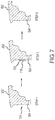
- Step 1 may include identifying the damaged portion 704 of mating surface 324.
- Step 1 may include pre-treatment as described herein.
- Mating surface 324 may be pre-treated.
- Pre-treatment may include chemically cleaning, sanding, grinding, drilling or the like.
- Pre-treatment of mating surface 324 may provide a clean surface for which added material may adhere.
- Step 2 illustrates mating surface 324 after having undergone an additive manufacturing process.
- Powder 710 for example, comprising similar chemical properties as mating surface 324, may be sprayed onto and adhered to mating surface 324.
- outer wheel half 202 may comprise aluminum.
- powder 710 for example, may comprise aluminum and aluminum oxide (alumina) which may be sprayed onto and adhered to outer wheel half 202 using an additive manufacturing process. This process may continue until powder 710 has at least filled the original geometric profile 702 of mating surface 324.
- Step 3 illustrates mating surface 324 after having performed post-treatment to mating surface 324.
- Post-treatment may include removing excess material from mating surface 324 until the original geometry of mating surface 324 is restored.
- Post-treatment may include, grinding, sanding, milling, drilling, boring, or the like.
- the additive manufacturing process may restore at least one of geometrical properties and/or structural properties to mating surface 324. Accordingly, mating surface 324 may be restored to a similar state as it was directly after original manufacture.
- any of the methods of repairing an aircraft wheel or brake part as described in FIG. 5 through FIG. 7 may be used to repair a surface of a torque plate or a piston housing.
- a method 800 for repairing a bore of an aircraft wheel and brake part is illustrated, in accordance with the present invention.
- the method 800 may include pre-treating a surface of the bore, in step 806.
- Step 808 may include using an additive manufacturing repair process.
- Step 810 may include drilling into the bore.
- a damaged portion 404 of bore 416 may be identified in step 1.
- Step 806 may include pre-treating a surface of the bore 516.
- Bore 516 may comprise a pre-determined diameter 520.
- step 808 may include, for example, cold spraying powder 510 onto the surface of bore 516 until the bore comprises a diameter which is less than the pre-determined diameter 520, wherein the powder retains the same physical state.
- step 808 may include, for example, spraying powder 510 onto the surface of bore 516 until the bore comprises a diameter which is less than the pre-determined diameter 520.
- step 808 may include any additive manufacturing repair process such as fused deposition modeling, polyjet 3D printing, electron beam freeform fabrication, direct metal laser sintering, electron-beam melting, selective laser melting, selective heat sintering, selective laser sintering, stereolithography, multiphoton photopolymerization, digital light processing, cold spray, and/or the like.
- a repair material may be applied to the surface of bore 516 until the bore comprises a diameter which is less than the pre-determined diameter 520, according to various types of additive manufacturing processes.
- Step 810 may include drilling into bore 516 until bore 516 comprises the pre-determined diameter 520. Pre-treatment may include chemically cleaning, sanding, grinding, drilling or the like.
- Step 806 may include pre-treating a surface of the bore.
- Step 808 may include using an additive manufacturing repair process.
- Step 810 may include drilling into the bore.
- Step 812 may include cutting threads into the bore.
- step 806 may include pre-treating a surface of the bore 516. Bore 516 may comprise a pre-determined diameter 520.
- step 808 may include, for example, cold spraying powder 510 onto the surface of bore 516 until the bore comprises a diameter which is less than the pre-determined diameter 520, wherein the powder retains the same physical state.
- step 808 may include, for example, spraying powder 510 onto the surface of bore 516 until the bore comprises a diameter which is less than the pre-determined diameter 520.
- step 808 may include any additive manufacturing repair process.
- a repair material may be applied to the surface of bore 516 until the bore comprises a diameter which is less than the pre-determined diameter 520, according to various types of additive manufacturing processes.
- Step 810 may include drilling into bore 516 until bore 516 comprises the pre-determined diameter 520. Pre-treatment may include chemically cleaning, sanding, grinding, drilling or the like.
- Step 812 may include cutting threads 402 into the inner surface 408 of bore 416.
- the method 900 may include pre-treating a surface of the aircraft part in step 904.
- Step 906 may include using an additive manufacturing repair process.
- Step 908 may include post-treating the aircraft part.
- a damaged portion 604 of an aircraft part such as, for example, second flange 208 may be identified.
- Step 904 may include pre-treating a surface, such as damaged portion 604 of the aircraft part.
- step 906 may include spraying powder 610, for example, onto the damaged portion 604 of the aircraft part until the powder 610 has at least filled an original geometric profile 602 of the aircraft part, wherein the powder 610 retains the same physical state.
- step 906 may include any additive manufacturing repair process.
- Step 908 may include post-treating the aircraft part. Pre-treatment may include chemically cleaning, sanding, grinding, drilling or the like. Post-treatment may include removing excess repair material from an aircraft part, such as second flange 208, until the original geometric profile 602 of second flange 208 (the aircraft part) is restored.
- a method for restoring structural properties of an aircraft wheel and brake part may be similar to the process as described in FIG. 8A and 8B and similar to the process as described in FIG. 9 .
- references to "various embodiments”, “one embodiment”, “an embodiment”, “an example embodiment”, etc. indicate that the embodiment described may include a particular feature, structure, or characteristic, but every embodiment may not necessarily include the particular feature, structure, or characteristic. Moreover, such phrases are not necessarily referring to the same embodiment. Further, when a particular feature, structure, or characteristic is described in connection with an embodiment, it is submitted that it is within the knowledge of one skilled in the art to affect such feature, structure, or characteristic in connection with other embodiments whether or not explicitly described. After reading the description, it will be apparent to one skilled in the relevant art(s) how to implement the disclosure in alternative embodiments.
Landscapes
- Engineering & Computer Science (AREA)
- Chemical & Material Sciences (AREA)
- Mechanical Engineering (AREA)
- Materials Engineering (AREA)
- Manufacturing & Machinery (AREA)
- Aviation & Aerospace Engineering (AREA)
- Chemical Kinetics & Catalysis (AREA)
- Metallurgy (AREA)
- Organic Chemistry (AREA)
- Transportation (AREA)
- Plasma & Fusion (AREA)
- Physics & Mathematics (AREA)
- Composite Materials (AREA)
- General Engineering & Computer Science (AREA)
- Coating By Spraying Or Casting (AREA)
Claims (4)
- Verfahren (800, 801) zur Reparatur einer Bohrung von zumindest entweder einem Flugzeugrad oder einem Flugzeugbremsenteil, umfassend:Vorbehandeln einer Fläche der Bohrung (806), wobei die Bohrung (416, 516) einen Durchmesser umfasst, der größer als ein vorher festgelegter Durchmesser ist;Verwenden eines additiven Herstellungsverfahrens zum Auftragen eines Reparaturmaterials (410, 510) auf die Fläche der Bohrung (416, 516); undBohren in die Bohrung (810), bis die Bohrung (416, 516) den vorher festgelegten Durchmesser (520) umfasst, wobei das Reparaturmaterial (410, 510) Partikel mit einem Durchmesser in einem Bereich von etwa 1 bis etwa 100 Mikrometern umfasst und wobei außerdem das Verwenden des additiven Herstellungsverfahrens ein Sprühen des Reparaturmaterials zumindest entweder auf das Flugzeugrad oder das Flugzeugbremsenteil mit Überschallgeschwindigkeiten umfasst, wobei das Reparaturmaterial zumindest entweder auf das Flugzeugrad oder auf das Bremsenteil aufprallt und sich plastisch verformt, derart, dass sich das Reparaturmaterial an eine Fläche von zumindest entweder dem Flugzeugrad oder dem Flugzeugbremsenteil anhaftet, wobei das Reparaturmaterial seinen Aggregatszustand beibehält, und wobei außerdem die Bohrung ein durchgehendes Loch umfasst, das während des additiven Herstellungsverfahrens beibehalten wird, dadurch gekennzeichnet, dass sich die Bohrung durch zumindest entweder das Flugzeugrad oder das Flugzeugbremsenteil erstreckt, wobei die Bohrung eine Achse umfasst und die Fläche im Wesentlichen parallel zur Achse verläuft.
- Verfahren (801) nach Anspruch 1, ferner umfassend ein Schneiden eines Gewindes (402) in die Bohrung (416, 812).
- Verfahren nach einem der vorhergehenden Ansprüche, wobei zumindest entweder das Flugzeugrad oder das Flugzeugbremsenteil Aluminium umfasst und das Reparaturmaterial (410, 510, 610) mindestens eines von Aluminium, Aluminiumoxid, Nickellegierung, Kupfer, Titan und rostfreiem Stahl umfasst.
- Verfahren nach einem der vorhergehenden Ansprüche, wobei das Verwenden des Reparaturprozesses durch additive Herstellung dazu konfiguriert ist, zumindest entweder geometrische Eigenschaften oder strukturelle Eigenschaften von zumindest entweder dem Flugzeugrad oder dem Flugzeugbremsenteil wiederherzustellen.
Applications Claiming Priority (1)
| Application Number | Priority Date | Filing Date | Title |
|---|---|---|---|
| US14/804,074 US20170022614A1 (en) | 2015-07-20 | 2015-07-20 | Methods for repair of aircraft wheel and brake parts |
Publications (2)
| Publication Number | Publication Date |
|---|---|
| EP3120968A1 EP3120968A1 (de) | 2017-01-25 |
| EP3120968B1 true EP3120968B1 (de) | 2018-11-21 |
Family
ID=56571143
Family Applications (1)
| Application Number | Title | Priority Date | Filing Date |
|---|---|---|---|
| EP16180372.1A Active EP3120968B1 (de) | 2015-07-20 | 2016-07-20 | Verfahren zur reparatur eines flugzeugrads und von bremsenteilen |
Country Status (2)
| Country | Link |
|---|---|
| US (1) | US20170022614A1 (de) |
| EP (1) | EP3120968B1 (de) |
Families Citing this family (17)
| Publication number | Priority date | Publication date | Assignee | Title |
|---|---|---|---|---|
| US20170355018A1 (en) | 2016-06-09 | 2017-12-14 | Hamilton Sundstrand Corporation | Powder deposition for additive manufacturing |
| WO2018033701A1 (en) * | 2016-08-18 | 2018-02-22 | Bae Systems Plc | Additive layer manufacturing |
| EP3284551A1 (de) * | 2016-08-19 | 2018-02-21 | BAE Systems PLC | Additivschichtherstellung |
| CN108274094B (zh) * | 2018-01-24 | 2020-05-22 | 西南交通大学 | 列车制动盘类构件的gmaw增材制造方法 |
| US10677300B2 (en) | 2018-02-02 | 2020-06-09 | Goodrich Corporation | Hybrid torque tube |
| US11092203B2 (en) | 2018-04-25 | 2021-08-17 | Goodrich Corporation | Hybrid torque bar |
| CN108788653B (zh) * | 2018-07-02 | 2019-11-08 | 诸暨市迅捷离合器有限公司 | 一种制动器磁轭的加工工艺 |
| CN109108269A (zh) * | 2018-09-13 | 2019-01-01 | 齐齐哈尔金车工业有限责任公司 | 机车车轮修复用铁基合金粉末及激光3d打印修复工艺 |
| US11254422B2 (en) * | 2018-12-14 | 2022-02-22 | Hydro-Aire, Inc. | System and method for reducing aircraft brake wear |
| US20200307304A1 (en) * | 2019-03-25 | 2020-10-01 | Goodrich Corporation | Bolted joint for wheel assemblies |
| US11459232B2 (en) * | 2019-04-08 | 2022-10-04 | Donna C. Mauro | Additive manufacturing methods for modification and improvement of the surfaces of micro-scale geometric features |
| US11124293B2 (en) | 2019-04-23 | 2021-09-21 | Goodrich Corporation | Integral bracket manifold for landing gear assemblies |
| CN111979535A (zh) * | 2020-07-22 | 2020-11-24 | 国营芜湖机械厂 | 一种起落架外筒表面冷喷涂再制造工艺 |
| US11344981B1 (en) * | 2020-11-23 | 2022-05-31 | Caterpillar Inc. | Method for remanufacturing internal spline components and splined connection |
| CN113500351B (zh) * | 2021-05-27 | 2023-05-30 | 沈阳北方飞机维修有限公司 | 一种用于飞机主轮上腐蚀裂纹的维修方法 |
| CN113387714B (zh) * | 2021-06-22 | 2022-12-09 | 上海航翼高新技术发展研究院有限公司 | 一种飞机碳刹车盘非摩擦面损伤修复方法 |
| FR3160119A1 (fr) | 2024-03-12 | 2025-09-19 | Safran Landing Systems | Procédé de réparation de pièces présentant un trou et dont la surface bordant le trou est détériorée |
Citations (14)
| Publication number | Priority date | Publication date | Assignee | Title |
|---|---|---|---|---|
| US5638591A (en) | 1995-05-24 | 1997-06-17 | Lamping; Bruce Alan | Method for restoring a wheel beadseat |
| US20020020734A1 (en) | 2000-06-23 | 2002-02-21 | Reinhold Meier | Method of repairing metallic components |
| US20020073982A1 (en) | 2000-12-16 | 2002-06-20 | Shaikh Furqan Zafar | Gas-dynamic cold spray lining for aluminum engine block cylinders |
| US20060045785A1 (en) | 2004-08-30 | 2006-03-02 | Yiping Hu | Method for repairing titanium alloy components |
| EP1674595A2 (de) | 2004-12-21 | 2006-06-28 | United Technologies Corporation | Strukturelle Reparatur durch Kaltspritzverfahren von Aluminumwerkstoffen |
| US20070181714A1 (en) | 2006-02-07 | 2007-08-09 | Honeywell International, Inc. | Apparatus for applying cold-spray to small diameter bores |
| US20100077587A1 (en) | 2008-09-26 | 2010-04-01 | Lufthansa Technik Ag | Method of repairing a housing of an aircraft engine |
| US20130209826A1 (en) * | 2012-02-13 | 2013-08-15 | Honeywell International Inc. | Methods for structural repair of components having damaged internally threaded openings and components repaired using such methods |
| WO2013184401A1 (en) | 2012-06-08 | 2013-12-12 | United Technologies Corporation | Method of working an airfoil using elevated temperature cmt welding |
| US20140117109A1 (en) | 2012-10-29 | 2014-05-01 | Christian Widener | Cold spray device and system |
| US20140115854A1 (en) | 2012-10-29 | 2014-05-01 | Christian Widener | Methods for cold spray repair |
| EP2778256A1 (de) | 2013-03-15 | 2014-09-17 | Bell Helicopter Textron Inc. | Verfahren unter Verwendung von Kaltspritztechniken zum Reparieren und Schützen von rotierenden Komponenten luftfahrttechnischer Antriebssysteme |
| WO2015069588A1 (en) | 2013-11-08 | 2015-05-14 | Siemens Energy, Inc. | Superalloy material deposition with interlayer material removal |
| EP2873620A1 (de) | 2013-11-14 | 2015-05-20 | Airbus Operations GmbH | Reparaturverfahren für Rumpfkomponenten von Luft- oder Raumfahrzeug |
Family Cites Families (14)
| Publication number | Priority date | Publication date | Assignee | Title |
|---|---|---|---|---|
| US3736067A (en) * | 1971-12-15 | 1973-05-29 | L R Akins | Reboring tool for brake spiders |
| US4953777A (en) * | 1986-10-08 | 1990-09-04 | Chromalloy Gas Turbine Corporation | Method for repairing by solid state diffusion metal parts having damaged holes |
| US5201455A (en) * | 1992-08-21 | 1993-04-13 | Westinghouse Electric Corp. | Method for metallurgical enhancement of a failed bolt hole |
| US6454156B1 (en) * | 2000-06-23 | 2002-09-24 | Siemens Westinghouse Power Corporation | Method for closing core printout holes in superalloy gas turbine blades |
| US6491208B2 (en) * | 2000-12-05 | 2002-12-10 | Siemens Westinghouse Power Corporation | Cold spray repair process |
| DE60335657D1 (de) * | 2002-09-25 | 2011-02-17 | Alcoa Inc | Beschichtetes fahrzeugrad und verfahren |
| US20050220995A1 (en) * | 2004-04-06 | 2005-10-06 | Yiping Hu | Cold gas-dynamic spraying of wear resistant alloys on turbine blades |
| US7479299B2 (en) * | 2005-01-26 | 2009-01-20 | Honeywell International Inc. | Methods of forming high strength coatings |
| US7676897B2 (en) * | 2005-03-17 | 2010-03-16 | Keate Robert A | Process of refurbishing brake components |
| US7552855B2 (en) * | 2005-10-13 | 2009-06-30 | United Technologies Corporation | Hole repair technique and apparatus |
| JP4710802B2 (ja) * | 2006-03-07 | 2011-06-29 | 日産自動車株式会社 | 円形の穴内面を備えた部材,円形の穴内面の加工方法および加工装置 |
| EP2019151B1 (de) * | 2007-07-27 | 2012-09-12 | Nissan Motor Co., Ltd. | Verfahren und Vorrichtung zum thermal gesprühten Filmformen |
| US8486249B2 (en) * | 2009-01-29 | 2013-07-16 | Honeywell International Inc. | Cold spray and anodization repair process for restoring worn aluminum parts |
| US9724708B2 (en) * | 2009-12-17 | 2017-08-08 | Partners In Innovation Ltd. | Garden watering device |
-
2015
- 2015-07-20 US US14/804,074 patent/US20170022614A1/en not_active Abandoned
-
2016
- 2016-07-20 EP EP16180372.1A patent/EP3120968B1/de active Active
Patent Citations (14)
| Publication number | Priority date | Publication date | Assignee | Title |
|---|---|---|---|---|
| US5638591A (en) | 1995-05-24 | 1997-06-17 | Lamping; Bruce Alan | Method for restoring a wheel beadseat |
| US20020020734A1 (en) | 2000-06-23 | 2002-02-21 | Reinhold Meier | Method of repairing metallic components |
| US20020073982A1 (en) | 2000-12-16 | 2002-06-20 | Shaikh Furqan Zafar | Gas-dynamic cold spray lining for aluminum engine block cylinders |
| US20060045785A1 (en) | 2004-08-30 | 2006-03-02 | Yiping Hu | Method for repairing titanium alloy components |
| EP1674595A2 (de) | 2004-12-21 | 2006-06-28 | United Technologies Corporation | Strukturelle Reparatur durch Kaltspritzverfahren von Aluminumwerkstoffen |
| US20070181714A1 (en) | 2006-02-07 | 2007-08-09 | Honeywell International, Inc. | Apparatus for applying cold-spray to small diameter bores |
| US20100077587A1 (en) | 2008-09-26 | 2010-04-01 | Lufthansa Technik Ag | Method of repairing a housing of an aircraft engine |
| US20130209826A1 (en) * | 2012-02-13 | 2013-08-15 | Honeywell International Inc. | Methods for structural repair of components having damaged internally threaded openings and components repaired using such methods |
| WO2013184401A1 (en) | 2012-06-08 | 2013-12-12 | United Technologies Corporation | Method of working an airfoil using elevated temperature cmt welding |
| US20140117109A1 (en) | 2012-10-29 | 2014-05-01 | Christian Widener | Cold spray device and system |
| US20140115854A1 (en) | 2012-10-29 | 2014-05-01 | Christian Widener | Methods for cold spray repair |
| EP2778256A1 (de) | 2013-03-15 | 2014-09-17 | Bell Helicopter Textron Inc. | Verfahren unter Verwendung von Kaltspritztechniken zum Reparieren und Schützen von rotierenden Komponenten luftfahrttechnischer Antriebssysteme |
| WO2015069588A1 (en) | 2013-11-08 | 2015-05-14 | Siemens Energy, Inc. | Superalloy material deposition with interlayer material removal |
| EP2873620A1 (de) | 2013-11-14 | 2015-05-20 | Airbus Operations GmbH | Reparaturverfahren für Rumpfkomponenten von Luft- oder Raumfahrzeug |
Non-Patent Citations (3)
| Title |
|---|
| ANONYMOUS: "Cold Spraying- Wikipedia, the free encyclopedia", 6 June 2015 (2015-06-06), XP055638372, Retrieved from the Internet <URL:https://en.wikipedia.org/w/index.php?title=Cold sprayinq&oldid=665751379> [retrieved on 20190820] |
| ANONYMOUS: "SST-A0027 Practical Cold Spray Coatings, Technical Data Sheet", CENTERLINE, March 2015 (2015-03-01), XP055638373, Retrieved from the Internet <URL:https://www.supersonicspray.com/uploads/documents/SST-TDS-A0027-PR-1_3-0315-1.pdf> [retrieved on 20190820] |
| DANIEL GREVING: "How Cold Spray Is Changing Aerospace Aftermarket Repair Strategies", 8 July 2016 (2016-07-08), pages 1 - 34, XP055638374, Retrieved from the Internet <URL:https://www.asminternational.orq/documents/10192/26746001/2+- +Greving.pdf/dde7bf0d-2277-43e0-ad44-e4a1386fee61> [retrieved on 20190820] |
Also Published As
| Publication number | Publication date |
|---|---|
| US20170022614A1 (en) | 2017-01-26 |
| EP3120968A1 (de) | 2017-01-25 |
Similar Documents
| Publication | Publication Date | Title |
|---|---|---|
| EP3120968B1 (de) | Verfahren zur reparatur eines flugzeugrads und von bremsenteilen | |
| EP2778256B1 (de) | Verfahren unter Verwendung von Kaltspritztechniken zum Reparieren und Schützen von rotierenden Komponenten luftfahrttechnischer Antriebssysteme | |
| Champagne | The repair of magnesium rotorcraft components by cold spray | |
| EP2236235B1 (de) | System zur Herstellung von Hochtemperaturzusatzstoffen zur Herstellung eines endkonturnahen Profileintrittskantenschutzes mit einem beschichteten Dorn | |
| EP2113634B1 (de) | Verfahren zur Reparatur eines Gasturbinenmotorgehäuses mit ausgetauschtem Flansch mittels Kaltmetallübertragung | |
| US20160279710A1 (en) | Aircraft brake rotor clip repair methods | |
| US20170057023A1 (en) | Piston and Method of Piston Remanufacturing | |
| KR20090007306A (ko) | 항공기 용도를 위한 알루미늄 합금을 포함하는 동적으로 응력이 가해진 구성요소의 수리 및 복원을 위한 방법 | |
| EP3218529A2 (de) | Maskierungsstopfen für kaltsprayreparatur bei einem senkbohrloch | |
| US7367488B2 (en) | Method of repair of thin wall housings | |
| EP3332902B1 (de) | Systeme und verfahren zur herstellung einer metallverstärkung der laufradschaufel eines turbotriebwerks | |
| CN103987478A (zh) | 脊箔以及制造脊箔的方法 | |
| EP3066233B1 (de) | Korrosionsverminderung für getriebe | |
| EP3066232B1 (de) | Schadenverminderung für getriebe | |
| Dahnel et al. | Analysis of tool wear and hole quality during ultrasonic assisted drilling (UAD) of carbon fibre composite (CFC)/titanium alloy (Ti6Al4V) stacks | |
| EP1634976A1 (de) | Verfahren zum Aufbringen einer verschleissbeständigen Schleifbeschichtung auf einem Turbinenteil | |
| US11806939B2 (en) | Kinetic disassembly of support structure system for additively manufactured rotating components | |
| US20080099220A1 (en) | Pipe, method for production thereof and corresponding tool | |
| WO2017083273A1 (en) | Thermal coating for mechanical seals | |
| EP3816482A1 (de) | Innen gedämpftes getriebe | |
| Bagade et al. | Effect of laser surface texturing on coating adherence and tribological properties of CuNiIn and MoS2 coating | |
| US20160076128A1 (en) | Thermal Spray Coating for Mechanical Face Seals | |
| US12146538B2 (en) | Systems and methods for manufacturing wear pads | |
| CZ26638U1 (cs) | Náprava kolejových vozidel s vysoce odolnými funkčními plocham | |
| EP3199659A1 (de) | Verfahren zur herstellung eines zylindrischen hochtemperaturbauteils für einen gasturbinenmotor |
Legal Events
| Date | Code | Title | Description |
|---|---|---|---|
| PUAI | Public reference made under article 153(3) epc to a published international application that has entered the european phase |
Free format text: ORIGINAL CODE: 0009012 |
|
| STAA | Information on the status of an ep patent application or granted ep patent |
Free format text: STATUS: THE APPLICATION HAS BEEN PUBLISHED |
|
| AK | Designated contracting states |
Kind code of ref document: A1 Designated state(s): AL AT BE BG CH CY CZ DE DK EE ES FI FR GB GR HR HU IE IS IT LI LT LU LV MC MK MT NL NO PL PT RO RS SE SI SK SM TR |
|
| AX | Request for extension of the european patent |
Extension state: BA ME |
|
| STAA | Information on the status of an ep patent application or granted ep patent |
Free format text: STATUS: REQUEST FOR EXAMINATION WAS MADE |
|
| 17P | Request for examination filed |
Effective date: 20170725 |
|
| RBV | Designated contracting states (corrected) |
Designated state(s): AL AT BE BG CH CY CZ DE DK EE ES FI FR GB GR HR HU IE IS IT LI LT LU LV MC MK MT NL NO PL PT RO RS SE SI SK SM TR |
|
| STAA | Information on the status of an ep patent application or granted ep patent |
Free format text: STATUS: EXAMINATION IS IN PROGRESS |
|
| 17Q | First examination report despatched |
Effective date: 20171120 |
|
| GRAP | Despatch of communication of intention to grant a patent |
Free format text: ORIGINAL CODE: EPIDOSNIGR1 |
|
| STAA | Information on the status of an ep patent application or granted ep patent |
Free format text: STATUS: GRANT OF PATENT IS INTENDED |
|
| INTG | Intention to grant announced |
Effective date: 20180530 |
|
| GRAS | Grant fee paid |
Free format text: ORIGINAL CODE: EPIDOSNIGR3 |
|
| GRAA | (expected) grant |
Free format text: ORIGINAL CODE: 0009210 |
|
| STAA | Information on the status of an ep patent application or granted ep patent |
Free format text: STATUS: THE PATENT HAS BEEN GRANTED |
|
| AK | Designated contracting states |
Kind code of ref document: B1 Designated state(s): AL AT BE BG CH CY CZ DE DK EE ES FI FR GB GR HR HU IE IS IT LI LT LU LV MC MK MT NL NO PL PT RO RS SE SI SK SM TR |
|
| REG | Reference to a national code |
Ref country code: CH Ref legal event code: EP |
|
| REG | Reference to a national code |
Ref country code: IE Ref legal event code: FG4D |
|
| REG | Reference to a national code |
Ref country code: DE Ref legal event code: R096 Ref document number: 602016007332 Country of ref document: DE |
|
| REG | Reference to a national code |
Ref country code: AT Ref legal event code: REF Ref document number: 1066991 Country of ref document: AT Kind code of ref document: T Effective date: 20181215 |
|
| REG | Reference to a national code |
Ref country code: NL Ref legal event code: MP Effective date: 20181121 |
|
| REG | Reference to a national code |
Ref country code: AT Ref legal event code: MK05 Ref document number: 1066991 Country of ref document: AT Kind code of ref document: T Effective date: 20181121 |
|
| PG25 | Lapsed in a contracting state [announced via postgrant information from national office to epo] |
Ref country code: AT Free format text: LAPSE BECAUSE OF FAILURE TO SUBMIT A TRANSLATION OF THE DESCRIPTION OR TO PAY THE FEE WITHIN THE PRESCRIBED TIME-LIMIT Effective date: 20181121 Ref country code: IS Free format text: LAPSE BECAUSE OF FAILURE TO SUBMIT A TRANSLATION OF THE DESCRIPTION OR TO PAY THE FEE WITHIN THE PRESCRIBED TIME-LIMIT Effective date: 20190321 Ref country code: NO Free format text: LAPSE BECAUSE OF FAILURE TO SUBMIT A TRANSLATION OF THE DESCRIPTION OR TO PAY THE FEE WITHIN THE PRESCRIBED TIME-LIMIT Effective date: 20190221 Ref country code: FI Free format text: LAPSE BECAUSE OF FAILURE TO SUBMIT A TRANSLATION OF THE DESCRIPTION OR TO PAY THE FEE WITHIN THE PRESCRIBED TIME-LIMIT Effective date: 20181121 Ref country code: BG Free format text: LAPSE BECAUSE OF FAILURE TO SUBMIT A TRANSLATION OF THE DESCRIPTION OR TO PAY THE FEE WITHIN THE PRESCRIBED TIME-LIMIT Effective date: 20190221 Ref country code: LT Free format text: LAPSE BECAUSE OF FAILURE TO SUBMIT A TRANSLATION OF THE DESCRIPTION OR TO PAY THE FEE WITHIN THE PRESCRIBED TIME-LIMIT Effective date: 20181121 Ref country code: HR Free format text: LAPSE BECAUSE OF FAILURE TO SUBMIT A TRANSLATION OF THE DESCRIPTION OR TO PAY THE FEE WITHIN THE PRESCRIBED TIME-LIMIT Effective date: 20181121 Ref country code: LV Free format text: LAPSE BECAUSE OF FAILURE TO SUBMIT A TRANSLATION OF THE DESCRIPTION OR TO PAY THE FEE WITHIN THE PRESCRIBED TIME-LIMIT Effective date: 20181121 Ref country code: ES Free format text: LAPSE BECAUSE OF FAILURE TO SUBMIT A TRANSLATION OF THE DESCRIPTION OR TO PAY THE FEE WITHIN THE PRESCRIBED TIME-LIMIT Effective date: 20181121 |
|
| PG25 | Lapsed in a contracting state [announced via postgrant information from national office to epo] |
Ref country code: PT Free format text: LAPSE BECAUSE OF FAILURE TO SUBMIT A TRANSLATION OF THE DESCRIPTION OR TO PAY THE FEE WITHIN THE PRESCRIBED TIME-LIMIT Effective date: 20190321 Ref country code: RS Free format text: LAPSE BECAUSE OF FAILURE TO SUBMIT A TRANSLATION OF THE DESCRIPTION OR TO PAY THE FEE WITHIN THE PRESCRIBED TIME-LIMIT Effective date: 20181121 Ref country code: AL Free format text: LAPSE BECAUSE OF FAILURE TO SUBMIT A TRANSLATION OF THE DESCRIPTION OR TO PAY THE FEE WITHIN THE PRESCRIBED TIME-LIMIT Effective date: 20181121 Ref country code: GR Free format text: LAPSE BECAUSE OF FAILURE TO SUBMIT A TRANSLATION OF THE DESCRIPTION OR TO PAY THE FEE WITHIN THE PRESCRIBED TIME-LIMIT Effective date: 20190222 Ref country code: NL Free format text: LAPSE BECAUSE OF FAILURE TO SUBMIT A TRANSLATION OF THE DESCRIPTION OR TO PAY THE FEE WITHIN THE PRESCRIBED TIME-LIMIT Effective date: 20181121 Ref country code: SE Free format text: LAPSE BECAUSE OF FAILURE TO SUBMIT A TRANSLATION OF THE DESCRIPTION OR TO PAY THE FEE WITHIN THE PRESCRIBED TIME-LIMIT Effective date: 20181121 |
|
| PG25 | Lapsed in a contracting state [announced via postgrant information from national office to epo] |
Ref country code: CZ Free format text: LAPSE BECAUSE OF FAILURE TO SUBMIT A TRANSLATION OF THE DESCRIPTION OR TO PAY THE FEE WITHIN THE PRESCRIBED TIME-LIMIT Effective date: 20181121 Ref country code: PL Free format text: LAPSE BECAUSE OF FAILURE TO SUBMIT A TRANSLATION OF THE DESCRIPTION OR TO PAY THE FEE WITHIN THE PRESCRIBED TIME-LIMIT Effective date: 20181121 Ref country code: DK Free format text: LAPSE BECAUSE OF FAILURE TO SUBMIT A TRANSLATION OF THE DESCRIPTION OR TO PAY THE FEE WITHIN THE PRESCRIBED TIME-LIMIT Effective date: 20181121 Ref country code: IT Free format text: LAPSE BECAUSE OF FAILURE TO SUBMIT A TRANSLATION OF THE DESCRIPTION OR TO PAY THE FEE WITHIN THE PRESCRIBED TIME-LIMIT Effective date: 20181121 |
|
| REG | Reference to a national code |
Ref country code: DE Ref legal event code: R026 Ref document number: 602016007332 Country of ref document: DE |
|
| PLBI | Opposition filed |
Free format text: ORIGINAL CODE: 0009260 |
|
| PG25 | Lapsed in a contracting state [announced via postgrant information from national office to epo] |
Ref country code: SM Free format text: LAPSE BECAUSE OF FAILURE TO SUBMIT A TRANSLATION OF THE DESCRIPTION OR TO PAY THE FEE WITHIN THE PRESCRIBED TIME-LIMIT Effective date: 20181121 Ref country code: EE Free format text: LAPSE BECAUSE OF FAILURE TO SUBMIT A TRANSLATION OF THE DESCRIPTION OR TO PAY THE FEE WITHIN THE PRESCRIBED TIME-LIMIT Effective date: 20181121 Ref country code: RO Free format text: LAPSE BECAUSE OF FAILURE TO SUBMIT A TRANSLATION OF THE DESCRIPTION OR TO PAY THE FEE WITHIN THE PRESCRIBED TIME-LIMIT Effective date: 20181121 Ref country code: SK Free format text: LAPSE BECAUSE OF FAILURE TO SUBMIT A TRANSLATION OF THE DESCRIPTION OR TO PAY THE FEE WITHIN THE PRESCRIBED TIME-LIMIT Effective date: 20181121 |
|
| PLAX | Notice of opposition and request to file observation + time limit sent |
Free format text: ORIGINAL CODE: EPIDOSNOBS2 |
|
| 26 | Opposition filed |
Opponent name: MOOG INC Effective date: 20190821 |
|
| PG25 | Lapsed in a contracting state [announced via postgrant information from national office to epo] |
Ref country code: SI Free format text: LAPSE BECAUSE OF FAILURE TO SUBMIT A TRANSLATION OF THE DESCRIPTION OR TO PAY THE FEE WITHIN THE PRESCRIBED TIME-LIMIT Effective date: 20181121 |
|
| PLBB | Reply of patent proprietor to notice(s) of opposition received |
Free format text: ORIGINAL CODE: EPIDOSNOBS3 |
|
| REG | Reference to a national code |
Ref country code: DE Ref legal event code: R119 Ref document number: 602016007332 Country of ref document: DE |
|
| PG25 | Lapsed in a contracting state [announced via postgrant information from national office to epo] |
Ref country code: MC Free format text: LAPSE BECAUSE OF FAILURE TO SUBMIT A TRANSLATION OF THE DESCRIPTION OR TO PAY THE FEE WITHIN THE PRESCRIBED TIME-LIMIT Effective date: 20181121 |
|
| REG | Reference to a national code |
Ref country code: CH Ref legal event code: PL |
|
| PG25 | Lapsed in a contracting state [announced via postgrant information from national office to epo] |
Ref country code: TR Free format text: LAPSE BECAUSE OF FAILURE TO SUBMIT A TRANSLATION OF THE DESCRIPTION OR TO PAY THE FEE WITHIN THE PRESCRIBED TIME-LIMIT Effective date: 20181121 |
|
| REG | Reference to a national code |
Ref country code: BE Ref legal event code: MM Effective date: 20190731 |
|
| PG25 | Lapsed in a contracting state [announced via postgrant information from national office to epo] |
Ref country code: DE Free format text: LAPSE BECAUSE OF NON-PAYMENT OF DUE FEES Effective date: 20200201 |
|
| PG25 | Lapsed in a contracting state [announced via postgrant information from national office to epo] |
Ref country code: LI Free format text: LAPSE BECAUSE OF NON-PAYMENT OF DUE FEES Effective date: 20190731 Ref country code: CH Free format text: LAPSE BECAUSE OF NON-PAYMENT OF DUE FEES Effective date: 20190731 Ref country code: BE Free format text: LAPSE BECAUSE OF NON-PAYMENT OF DUE FEES Effective date: 20190731 Ref country code: LU Free format text: LAPSE BECAUSE OF NON-PAYMENT OF DUE FEES Effective date: 20190720 |
|
| PG25 | Lapsed in a contracting state [announced via postgrant information from national office to epo] |
Ref country code: IE Free format text: LAPSE BECAUSE OF NON-PAYMENT OF DUE FEES Effective date: 20190720 |
|
| PLBP | Opposition withdrawn |
Free format text: ORIGINAL CODE: 0009264 |
|
| PLAY | Examination report in opposition despatched + time limit |
Free format text: ORIGINAL CODE: EPIDOSNORE2 |
|
| PLBC | Reply to examination report in opposition received |
Free format text: ORIGINAL CODE: EPIDOSNORE3 |
|
| PG25 | Lapsed in a contracting state [announced via postgrant information from national office to epo] |
Ref country code: CY Free format text: LAPSE BECAUSE OF FAILURE TO SUBMIT A TRANSLATION OF THE DESCRIPTION OR TO PAY THE FEE WITHIN THE PRESCRIBED TIME-LIMIT Effective date: 20181121 |
|
| PLCK | Communication despatched that opposition was rejected |
Free format text: ORIGINAL CODE: EPIDOSNREJ1 |
|
| REG | Reference to a national code |
Ref country code: DE Ref legal event code: R100 Ref document number: 602016007332 Country of ref document: DE |
|
| PG25 | Lapsed in a contracting state [announced via postgrant information from national office to epo] |
Ref country code: HU Free format text: LAPSE BECAUSE OF FAILURE TO SUBMIT A TRANSLATION OF THE DESCRIPTION OR TO PAY THE FEE WITHIN THE PRESCRIBED TIME-LIMIT; INVALID AB INITIO Effective date: 20160720 Ref country code: MT Free format text: LAPSE BECAUSE OF FAILURE TO SUBMIT A TRANSLATION OF THE DESCRIPTION OR TO PAY THE FEE WITHIN THE PRESCRIBED TIME-LIMIT Effective date: 20181121 |
|
| PLBN | Opposition rejected |
Free format text: ORIGINAL CODE: 0009273 |
|
| STAA | Information on the status of an ep patent application or granted ep patent |
Free format text: STATUS: OPPOSITION REJECTED |
|
| 27O | Opposition rejected |
Effective date: 20210617 |
|
| PG25 | Lapsed in a contracting state [announced via postgrant information from national office to epo] |
Ref country code: MK Free format text: LAPSE BECAUSE OF FAILURE TO SUBMIT A TRANSLATION OF THE DESCRIPTION OR TO PAY THE FEE WITHIN THE PRESCRIBED TIME-LIMIT Effective date: 20181121 |
|
| P01 | Opt-out of the competence of the unified patent court (upc) registered |
Effective date: 20230522 |
|
| PGFP | Annual fee paid to national office [announced via postgrant information from national office to epo] |
Ref country code: GB Payment date: 20250619 Year of fee payment: 10 |
|
| PGFP | Annual fee paid to national office [announced via postgrant information from national office to epo] |
Ref country code: FR Payment date: 20250620 Year of fee payment: 10 |