EP4215768B1 - Leckresistente nachgiebige buchse - Google Patents
Leckresistente nachgiebige buchse Download PDFInfo
- Publication number
- EP4215768B1 EP4215768B1 EP23152538.7A EP23152538A EP4215768B1 EP 4215768 B1 EP4215768 B1 EP 4215768B1 EP 23152538 A EP23152538 A EP 23152538A EP 4215768 B1 EP4215768 B1 EP 4215768B1
- Authority
- EP
- European Patent Office
- Prior art keywords
- segment
- section
- width
- channels
- bushing
- Prior art date
- Legal status (The legal status is an assumption and is not a legal conclusion. Google has not performed a legal analysis and makes no representation as to the accuracy of the status listed.)
- Active
Links
Images




Classifications
-
- F—MECHANICAL ENGINEERING; LIGHTING; HEATING; WEAPONS; BLASTING
- F16—ENGINEERING ELEMENTS AND UNITS; GENERAL MEASURES FOR PRODUCING AND MAINTAINING EFFECTIVE FUNCTIONING OF MACHINES OR INSTALLATIONS; THERMAL INSULATION IN GENERAL
- F16C—SHAFTS; FLEXIBLE SHAFTS; ELEMENTS OR CRANKSHAFT MECHANISMS; ROTARY BODIES OTHER THAN GEARING ELEMENTS; BEARINGS
- F16C17/00—Sliding-contact bearings for exclusively rotary movement
- F16C17/02—Sliding-contact bearings for exclusively rotary movement for radial load only
-
- F—MECHANICAL ENGINEERING; LIGHTING; HEATING; WEAPONS; BLASTING
- F16—ENGINEERING ELEMENTS AND UNITS; GENERAL MEASURES FOR PRODUCING AND MAINTAINING EFFECTIVE FUNCTIONING OF MACHINES OR INSTALLATIONS; THERMAL INSULATION IN GENERAL
- F16C—SHAFTS; FLEXIBLE SHAFTS; ELEMENTS OR CRANKSHAFT MECHANISMS; ROTARY BODIES OTHER THAN GEARING ELEMENTS; BEARINGS
- F16C17/00—Sliding-contact bearings for exclusively rotary movement
- F16C17/12—Sliding-contact bearings for exclusively rotary movement characterised by features not related to the direction of the load
- F16C17/18—Sliding-contact bearings for exclusively rotary movement characterised by features not related to the direction of the load with floating brasses or brushing, rotatable at a reduced speed
-
- F—MECHANICAL ENGINEERING; LIGHTING; HEATING; WEAPONS; BLASTING
- F16—ENGINEERING ELEMENTS AND UNITS; GENERAL MEASURES FOR PRODUCING AND MAINTAINING EFFECTIVE FUNCTIONING OF MACHINES OR INSTALLATIONS; THERMAL INSULATION IN GENERAL
- F16C—SHAFTS; FLEXIBLE SHAFTS; ELEMENTS OR CRANKSHAFT MECHANISMS; ROTARY BODIES OTHER THAN GEARING ELEMENTS; BEARINGS
- F16C17/00—Sliding-contact bearings for exclusively rotary movement
- F16C17/12—Sliding-contact bearings for exclusively rotary movement characterised by features not related to the direction of the load
- F16C17/22—Sliding-contact bearings for exclusively rotary movement characterised by features not related to the direction of the load with arrangements compensating for thermal expansion
-
- F—MECHANICAL ENGINEERING; LIGHTING; HEATING; WEAPONS; BLASTING
- F16—ENGINEERING ELEMENTS AND UNITS; GENERAL MEASURES FOR PRODUCING AND MAINTAINING EFFECTIVE FUNCTIONING OF MACHINES OR INSTALLATIONS; THERMAL INSULATION IN GENERAL
- F16C—SHAFTS; FLEXIBLE SHAFTS; ELEMENTS OR CRANKSHAFT MECHANISMS; ROTARY BODIES OTHER THAN GEARING ELEMENTS; BEARINGS
- F16C27/00—Elastic or yielding bearings or bearing supports, for exclusively rotary movement
-
- F—MECHANICAL ENGINEERING; LIGHTING; HEATING; WEAPONS; BLASTING
- F16—ENGINEERING ELEMENTS AND UNITS; GENERAL MEASURES FOR PRODUCING AND MAINTAINING EFFECTIVE FUNCTIONING OF MACHINES OR INSTALLATIONS; THERMAL INSULATION IN GENERAL
- F16C—SHAFTS; FLEXIBLE SHAFTS; ELEMENTS OR CRANKSHAFT MECHANISMS; ROTARY BODIES OTHER THAN GEARING ELEMENTS; BEARINGS
- F16C27/00—Elastic or yielding bearings or bearing supports, for exclusively rotary movement
- F16C27/02—Sliding-contact bearings
Definitions
- the present application relates to the art of bushings and, more particularly, to a compliant bushing that resists leakage.
- Bushings are often used as bearings to support a shaft that may rotate and/or slide relative to, for example, a fixed support.
- the bushing is fixedly secured to the fixed support.
- a clearance exists between the bushing and the shaft. The clearance allows for installation of the shaft, installation of the busing, as well as accommodates dimensional changes in the bushing due to operational temperatures and/or wear. Tight clearance is needed to mitigate risks of potential leaking between opposite ends of bushings. On the other hand, a clearance that is too tight makes installation difficult.
- the bushing may include a split through the entire length of the bushing.
- the split allows for a measure of compliance during installation along with maintenance of desired clearances.
- the split may introduce an unwanted leakage path beyond that provided by the closely controlled clearances. In other words, any installation improvements are offset by a higher risk of leaking.
- US7665747B2 discloses a rack and pinion steering gear assembly including a housing and a rack, with a bushing in between having axially extending recesses enhance the flexibility of the bushing.
- US9989084B2 discloses a slide bearing having a main body around a shaft body, and an elastic ring on the main body.
- the elastic ring comprises slits running axially from end towards another end.
- US 11118623B2 discloses a rack bush for vehicle steering apparatus having a bush body with an outer surface in contact with an inner surface of a rack housing and an inner surface that is in contact with a rack bar, the bush body having slits arranged circumferentially to absorb impact between the bar and body.
- US9995337B2 discloses a rack bushing supported by an annular elastic member in a housing having a bushing body and a flange portion extending radially, the bushing body having a second axial slit extending from a second axial end to a middle portion in an axial direction.
- US20020085778A1 discloses an expandable rack bushing having a tubular portion with front slots and rear slots, with an axial overlap between the front and rear slots permits expansion and retraction of the tubular portion.
- GB2269211A discloses a cylindrical journal bearing bush having a bearing surface having a plurality of lubrication grooves defining first and second groove sets, each groove including a segment angular to the direction of rotation so that that lubricant is distributed both circumferentially and axially on the surface.
- each of the first plurality of channels includes a first side portion and a second side portion that join at the terminal end portion; and each of the second plurality of channels includes a first side section and a second side section that join at the terminal end section.
- the terminal end portion includes a curvilinear portion.
- the first side portion includes a first segment a second segment, and the second side portion includes a third segment and a fourth segment, wherein the first segment and the third segment extend at the first angle relative to the axial axis.
- the second segment and the fourth segment extend at a non-zero angle relative to the axial axis.
- the first side section includes a first segment section and a second segment section
- the second side section includes a third segment section and a fourth segment section.
- the first segment is spaced from the second segment at a first width
- the third segment is spaced from the fourth segment at a second width
- the first segment section is spaced from the second segment section at a third width and the third segment section is spaced from the fourth segment section at a fourth width.
- the second width is non-uniform along the axial axis.
- the first width, the second width of each of the first plurality of channels and each of the third width and the fourth width of each of the second plurality of channels are substantially constant along a hoop direction of the bushing.
- the second width of each of the first plurality of channels and the fourth width of each of the second plurality of channels are non-uniform along the hoop direction.
- each of the first plurality of channels includes a first side portion and a second side portion that join at the terminal end portion; and each of the second plurality of channels includes a first side section and a second side section that join at the terminal end section.
- the first side portion includes a first segment and a second segment
- the second side portion includes a third segment and a fourth segment, wherein the first segment and the third segment extend at the first angle relative to the axial axis.
- the first side section includes a first segment section and a second segment section
- the second side section includes a third segment section and a fourth segment section
- the first segment is spaced from the second segment a first width
- the third segment is spaced from the fourth segment a second width
- the first segment section is spaced from the second segment section a third width and the third segment section is spaced from the fourth segment section a fourth width.
- the second width is non-uniform along the axial axis
- the first width and the third width are substantially constant along a hoop direction of the bushing
- the second width and the fourth width are non-uniform along the hoop direction.
- Aircraft 10 includes a fuselage 14 supporting a pair of wings, one of which is shown at 16, and a tail 18.
- Fuselage 14 defines, in part, a cabin 20 that accommodates crew and/or passengers.
- Wing 16 supports a first engine 24 and a second engine 25.
- Fuselage 14 includes a cabin air system 30 that is connected to first engine 24. Cabin air system 30 may also be connected to second engine 25.
- cabin air system 30 includes an air intake 34 at first engine 24, an air conditioner 36, and an air mixing unit 38.
- An air filter 40 filters air passing into an air circulation circuit 42.
- An exhaust 44 discharges air from air circulation circuit 42 adjacent to tail 18.
- a mechanical system, shown in the form of a bleed air valve 46 provides an interface between first engine 24 and air conditioner 36.
- bleed air valve 46 includes a housing 50 including an inlet 52 and an outlet 54.
- a controlling air inlet 56 projects outwardly from 50 between inlet 52 and outlet 54.
- a valve member 58 is disposed in housing 50.
- Valve member 58 selectively connected inlet 52 and outlet 54.
- Valve member 58 includes a hub 60 supported on a shaft 62 having a shaft axis "A".
- a first leak resistant compliant bushing 64 and a second leak resistant compliant bushing 66 provide a wear resistant interface between hub 60 and shaft 62.
- Openings 68 on shaft 62 are provided to fluidly connect controlling air with the interior of valve member 58 which provides an axial driving force.
- valve member 58 transitions on shaft 62 along the shaft axis "A" when controlled by the pressure from 56 (passing through holes 68) to fluidically connect air passing from first engine 24 through air inlet 52 to valve outlet 54.
- Leak resistant compliant bushing 64 includes a body 74 having a first end 76 and a second end 78.
- body 74 is formed from a metal or metal alloy.
- body 74 may also be formed from polymeric, fiber-reinforced polymer-matrix composites or hybrid (e.g., metallic/polymeric or metallic/composite) materials.
- An outer surface 80 extends between first end 76 and second end 78.
- an inner surface 82 extends between first end 76 and second end 78.
- An axial axis "B” extends between first end 76 and second end 78.
- a hoop axis "C” defining a hoop direction circumscribes outer surface 80.
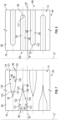
- a first plurality of channels 86 extends from first end 76 towards second end 78.
- a second plurality of through-thickness channels 88 extends from second end 78 towards first end 76.
- each of the first plurality of channels 86 terminates short of second end 78 at a terminal end 90.
- Each of the second plurality of channels 88 terminates short of first end 76 at a terminal end section 92.
- each of the first plurality of channels 86 and second plurality of channels 88 extend entirely through body 74 (e.g., from outer surface 80 through inner surface 82).
- Each of the first plurality of channels 86 includes a first side portion 95 and a second side portion 96 that extend from first end 76 and converge at terminal end 90.
- Each of the second plurality of channels 88 includes a first side section 98 and a second side section 99 that extend from second end 78 and converge at terminal end portion 92.
- first side portion 95 includes a first segment 105 that extends substantially parallel to axial axis "B” and a second segment 106 that extends at an angle relative to axial axis "B".
- second side portion 96 includes a third segment 107 that extends substantially parallel to axial axis "B” and a fourth segment 108 that extends at an angle relative to axial axis "B”.
- First side section 98 includes a first segment section 110 that extends substantially parallel to axial axis "B” and a second segment section 111 that extends at an angle relative to axial axis "B".
- second side section 99 includes a first segment section 113 that extends substantially parallel to axial axis "B" and a fourth segment section 114 that extends at an angle relative to axial axis "B".
- First and second pluralities of channels 86 and 88 allow body 74 to have a circumferential stiffness that is lower than a corresponding solid bushing of the same material, such that the bushing is easier to install reducing tooling required and cost. Further, unlike split bushings, channels 86 and 88 do not extend fully from end 76 to 78 thus leakage is equivalent to a solid bushing, and less than a split bushing.
- first segment 105 and second segment 106 extend into body 74 along axes that are substantially parallel to axial axis "B”.
- third segment 107 and fourth segment 108 extend into body 74 along axes that are substantially parallel to axis "B”.
- Second segment 105 and fourth segment 108 join at terminal end 90 having a substantially curvilinear profile.
- First segment section 110 and second segment section 111 extend into body 74 along axes that are substantially parallel to axial axis "B".
- first segment section 113 and fourth segment section 114 extend into body 74 along axes that are substantially parallel to axial axis "B”.
- Second segment section 111 and fourth segment section 114 join at terminal end 92 having a substantially curvilinear profile.
- First side portion 95 includes a first segment 121, a second segment 122, and a third segment 123.
- First segment 121 extends substantially parallel to axial axis "B" while second segment 122 and third segment 123 extend at different angles relative to axial axis "B".
- Second side portion 96 includes a fourth segment 127, a fifth segment 128, and a sixth segment 129.
- Fourth segment 127 extends substantially parallel to axial axis "B” while fifth segment 128 and sixth segment 129 extend at different angles relative to axial axis "B".
- portions of the first plurality of channels 86 and/or portions of the second plurality of channels 88 can be defined with varied non-zero angles with respect to axial axis "A", creating for example, non-linear convex or concave profiles.
- First side section 98 includes a first segment section 131, a second segment section 132, and a third segment section 133.
- First segment section 131 extends substantially parallel to axial axis "B" while second segment section 132 and third segment section 133 extend at different angles relative to axial axis "B".
- Second side section 99 includes a fourth segment section 135, a fifth segment section 136, and a sixth segment section 138.
- Fourth segment section 135 extends substantially parallel to axial axis "B” while fifth section 136 and sixth segment section 137 extend at different angles relative to axial axis "B".
- First side portion 95 and second side portion 96 of each of the first plurality of channels 86 extend substantially parallel to one another and to axial axis "B". In a non-limiting example, first side portion 95 and second side portion 96 join at a curvilinear portion 141 defined by terminal end 90. Similarly, first side section 98 and second side section 99 extend substantially parallel to one another and to axial axis "B". In a non-limiting example, first side section 98 and second side section 99 join at a curvilinear portion 142 defined by terminal end section 92. Curvilinear portion 142 can be defined by either a constant or a varied radius.
- first side portion 95 and second side portion 96 of each of the first plurality of channels 86 extend substantially parallel to one another and to at a constant angle relative to axial axis "B".
- first side section 98 and second side section 99 extend substantially parallel to one another and at a constant angle relative to axial axis "B”.
- first side portion 95 and second side portion 96 of each of the first plurality of channels 86 extend substantially parallel to one another and to at a varying angle relative to axial axis "B”.
- first side section 98 and second side section 99 extend substantially parallel to one another and at a varying angle relative to axial axis "B".
- first and second pluralities of channels 86 and 88 allow first and second pluralities of channels 86 and 88 to be formed with conventional machining processes using, for example, a rotary bit.
- individual ones of the first plurality of channels 86 and/or the second plurality of channels 88 may be sized to possess the same (e.g., uniform sizing and positioning of the channels) or different (e.g., non-uniform sizing and/or positioning of individual channels).
- first segment 104 is spaced from third segment 107 of each of the first plurality of channels 86 a first width "D1".
- Second segment 105 is spaced from fourth segment 108 of each of the first plurality of channels 86 a second width "D2" that varies along the axial axis "A”.
- First segment section 110 is spaced from third segment section 112 of each of the second plurality of channels 88 a third width D3".
- Second segment section 111 is spaced from fourth segment section 113 of each of the second plurality of channels a fourth width "D4".
- the first width "D1" and the third width “D3" are substantially uniform (e.g., constant along hoop direction "C" as shown in FIG. 11 and the second width "D2" and fourth width "D4" are non-uniform (e.g., not constant) along the hoop direction "C" as shown in FIG. 12 .
- other more complex relationships between mutual sizing of variables D1, D2, D3 and D4 can be defined according to structural optimization of bushings, performed for example by the Finite Element Method.
- the non-limiting examples shown and described herein represent various channel geometries that promote compliance in an annular bushing without introducing a leak path such as would be created by a split.
- Different channel geometries create varying degrees of compliance that may accommodate a wide range of operating conditions and installation methods.
- other materials particularly thermally responsive materials may also be employed.
- the leak resistant compliant bushing may take on a wide range of shapes, including circular, as shown in FIGS. 3-4 , and non-circular cross-sections, as shown in FIGS. 13A-C , as well as a wide range of sizes.
- non-circular cross-sections can include, among others, quadratic, and rectangular shapes ( FIG. 13A-B ), polygonal shapes with different number of sides, e.g., triangular, pentangular, hexagonal (as illustrated in FIG. 13C ) shapes, elliptical shapes, or other multi-segment shapes combining linear and/or curved profiles in different segments.
Landscapes
- Engineering & Computer Science (AREA)
- General Engineering & Computer Science (AREA)
- Mechanical Engineering (AREA)
- Gasket Seals (AREA)
- Sliding-Contact Bearings (AREA)
Claims (12)
- Leckresistente nachgiebige Buchse (64), umfassend:einen Körper (74), der ein erstes Ende (76), ein zweites Ende (78), eine Außenfläche (80) und eine Innenfläche (82) aufweist, die einen Durchgang definieren, wobei sich die Außenfläche (80) und die Innenfläche (82) zwischen dem ersten Ende (76) und dem zweiten Ende (78) erstrecken und eine axiale Achse (B) definieren;eine erste Vielzahl von Kanälen (86), die sich von dem ersten Ende (76) in den Körper (74) erstreckt, wobei jeder der ersten Vielzahl von Kanälen (86) ein Abschlussende (90) beinhaltet, das von dem zweiten Ende (78) beabstandet ist, wobei jeder der ersten Vielzahl von Kanälen (86) eine erste Mittelachse beinhaltet, die sich von dem ersten Ende (76) durch das Abschlussende (90) erstreckt; undeine zweite Vielzahl von durchgehenden Kanälen (88), die sich von dem zweiten Ende (78) in den Körper (74) erstreckt, wobei sich jeder der zweiten Vielzahl von Kanälen (88) zwischen benachbarten der ersten Vielzahl von Kanälen (86) erstreckt und ein Abschlussendteilstück (92) beinhaltet, das von dem ersten Ende (76) beabstandet ist, wobei jeder der zweiten Vielzahl von Kanälen (88) eine zweite Mittelachse beinhaltet, die sich von dem zweiten Ende (78) durch das Abschlussende (92) erstreckt, dadurch gekennzeichnet, dass sich die erste Mittelachse und die zweite Mittelachse jeweils in einem von Null verschiedenen Winkel relativ zu der axialen Achse (B) über den Körper (74) erstrecken.
- Leckresistente nachgiebige Buchse (64) nach Anspruch 1, wobei jeder der ersten Vielzahl von Kanälen (86) einen ersten Seitenabschnitt (95) und einen zweiten Seitenabschnitt (96) beinhaltet, die an dem Abschlussende (90) zusammenlaufen; und jeder der zweiten Vielzahl von Kanälen (88) ein erstes Seitenteilstück (98) und ein zweites Seitenteilstück (99) umfasst, die an dem Abschlussendteilstück (92) zusammenlaufen.
- Leckresistente nachgiebige Buchse (64) nach Anspruch 2, wobei das Abschlussende (90) einen gekrümmten Abschnitt beinhaltet.
- Leckresistente nachgiebige Buchse (64) nach Anspruch 2 oder 3, wobei der erste Seitenabschnitt (95) ein erstes Segment (105) und ein zweites Segment (106) beinhaltet und der zweite Seitenabschnitt (96) ein drittes Segment (107) und ein viertes Segment (108) beinhaltet, wobei sich das erste Segment (105) und das dritte Segment (108) in einem ersten Winkel relativ zu der axialen Achse (B) erstrecken.
- Leckresistente nachgiebige Buchse (64) nach Anspruch 4, wobei sich das zweite Segment (106) und das vierte Segment (108) in einem von Null verschiedenen Winkel relativ zu der axialen Achse (B) erstrecken.
- Leckresistente nachgiebige Buchse (64) nach Anspruch 4 oder 5, wobei das erste Seitenteilstück (98) ein erstes Segmentteilstück (110) und ein zweites Segmentteilstück (111) beinhaltet und das zweite Seitenteilstück (99) ein drittes Segmentteilstück (113) und ein viertes Segmentteilstück (114) beinhaltet.
- Leckresistente nachgiebige Buchse (64) nach Anspruch 6,wobei das erste Segment (105) bei einer ersten Breite des dritten Segments (107) beabstandet ist und das zweite Segment (106) bei einer zweiten Breite von dem vierten Segment (108) beabstandet ist undwobei das erste Segmentteilstück (110) bei einer dritten Breite von dem dritten Segmentteilstück (113) beabstandet ist und das zweite Segmentteilstück (111) bei einer vierten Breite von dem vierten Segmentteilstück (114) beabstandet ist.
- Leckresistente nachgiebige Buchse (64) nach Anspruch 7, wobei die zweite Breite entlang der axialen Achse (B) ungleichmäßig ist.
- Leckresistente nachgiebige Buchse (64) nach Anspruch 7 oder 8, wobei die erste Breite und die zweite Breite jedes der ersten Vielzahl von Kanälen (86) und die dritte Breite und die vierte Breite jedes der zweiten Vielzahl von Kanälen (88) entlang einer Umfangsrichtung (C) der Buchse (64) im Wesentlichen konstant sind.
- Leckresistente nachgiebige Buchse (64) nach Anspruch 7, wobei die zweite Breite jedes der ersten Vielzahl von Kanälen (86) und die vierte Breite jedes der zweiten Vielzahl von Kanälen (88) entlang einer Umfangsrichtung (C) der Buchse (64) ungleichmäßig sind.
- Luftfahrzeug (10), umfassend:einen Rumpf (14);mindestens ein Triebwerk (24), das durch den Rumpf (14) gestützt wird;ein mechanisches System, das in dem Rumpf (14) angeordnet ist, wobei das mechanische System eine Welle (62) beinhaltet, die durch eine leckresistente nachgiebige Buchse (64) nach einem der vorhergehenden Ansprüche gestützt wird.
- Luftfahrzeug (10) nach Anspruch 11,wobei das erste Seitenteilstück (98) ein erstes Segmentteilstück (110) und ein zweites Segmentteilstück (111) beinhaltet und das zweite Seitenteilstück (99) ein drittes Segmentteilstück (113) und ein viertes Segmentteilstück (114) beinhaltet,wobei das erste Segment (105) um eine erste Breite von dem dritten Segment (107) beabstandet ist und das zweite Segment (106) um eine zweite Breite von dem vierten Segment (108) beabstandet ist,wobei das erste Segmentteilstück (110) um eine dritte Breite von dem dritten Segmentteilstück (113) beabstandet ist und das zweite Segmentteilstück (111) um eine vierte Breite von dem vierten Segmentteilstück (114) beabstandet ist,wobei die zweite Breite entlang der axialen Achse (B) ungleichmäßig ist,wobei die erste Breite und die dritte Breite entlang einer Umfangsrichtung (C) der Buchse (64) im Wesentlichen konstant sind undwobei die zweite Breite und die vierte Breite entlang der Umfangsrichtung (C) ungleichmäßig sind.
Applications Claiming Priority (1)
| Application Number | Priority Date | Filing Date | Title |
|---|---|---|---|
| US17/579,724 US11713784B1 (en) | 2022-01-20 | 2022-01-20 | Leak resistant compliant bushing |
Publications (2)
| Publication Number | Publication Date |
|---|---|
| EP4215768A1 EP4215768A1 (de) | 2023-07-26 |
| EP4215768B1 true EP4215768B1 (de) | 2024-11-13 |
Family
ID=85017941
Family Applications (1)
| Application Number | Title | Priority Date | Filing Date |
|---|---|---|---|
| EP23152538.7A Active EP4215768B1 (de) | 2022-01-20 | 2023-01-19 | Leckresistente nachgiebige buchse |
Country Status (2)
| Country | Link |
|---|---|
| US (1) | US11713784B1 (de) |
| EP (1) | EP4215768B1 (de) |
Families Citing this family (1)
| Publication number | Priority date | Publication date | Assignee | Title |
|---|---|---|---|---|
| US10837677B2 (en) * | 2018-09-05 | 2020-11-17 | Ojjo, Inc. | Multi-piece truss legs and related couplers |
Family Cites Families (13)
| Publication number | Priority date | Publication date | Assignee | Title |
|---|---|---|---|---|
| US2366653A (en) * | 1944-03-20 | 1945-01-02 | Thomas J Risk | Bobbin clutch for spindle blades |
| US3501182A (en) | 1968-07-12 | 1970-03-17 | Frank Buchsbaum | Gear hub clamp |
| US4605363A (en) | 1985-03-25 | 1986-08-12 | Sundstrand Corporation | Gear pump with pivoted bushings that can deflect |
| US5383811A (en) * | 1991-05-31 | 1995-01-24 | Dana Corporation | Flexible non-metallic bearing liner for telescopic steering column |
| CA2082247C (en) | 1992-07-29 | 1996-05-14 | Harvey Kallenberger | Lubrication groove arrangement for a journal bearing |
| US5477673A (en) * | 1994-08-10 | 1995-12-26 | Pratt & Whitney Canada Inc. | Handling bleed valve |
| US6122905A (en) * | 1998-02-13 | 2000-09-26 | Pratt & Whitney Canada Corp. | Compressor bleed valve |
| US6485180B2 (en) | 2001-01-04 | 2002-11-26 | Delphi Technologies, Inc. | Expandable rack bushing |
| US7665747B2 (en) * | 2006-10-13 | 2010-02-23 | Gm Global Technology Operations, Inc. | Steering gear assembly having rack bushing |
| JP6434327B2 (ja) * | 2015-02-03 | 2018-12-05 | オイレス工業株式会社 | 滑り軸受 |
| JP2017087972A (ja) | 2015-11-10 | 2017-05-25 | 株式会社ジェイテクト | 転舵軸支持構造 |
| EP3343054A1 (de) * | 2016-12-28 | 2018-07-04 | Grundfos Holding A/S | Lagerkäfig für mehrstufige kreiselpumpe |
| KR102207576B1 (ko) * | 2019-11-07 | 2021-01-26 | 현대모비스 주식회사 | 차량용 조향장치의 랙부시 |
-
2022
- 2022-01-20 US US17/579,724 patent/US11713784B1/en active Active
-
2023
- 2023-01-19 EP EP23152538.7A patent/EP4215768B1/de active Active
Also Published As
| Publication number | Publication date |
|---|---|
| EP4215768A1 (de) | 2023-07-26 |
| US20230228293A1 (en) | 2023-07-20 |
| US11713784B1 (en) | 2023-08-01 |
Similar Documents
| Publication | Publication Date | Title |
|---|---|---|
| EP2538036B1 (de) | Integrale Anordnung von Lagerträger und Zentrierfeder für ein Gasturbinentriebwerk | |
| EP0937864B1 (de) | Leitschaufelanordnung für eine axiale Strömungsmaschine | |
| EP2565424B1 (de) | Drehmomentrahmen und asymmetrisches Gleitlager für ein Fangetriebesystem | |
| EP2325458B2 (de) | Balgvorladung und Zentrierschraube für ein Lüfterantriebsgetriebesystem | |
| EP3199839B1 (de) | Getriebeplanetenpressfilmdämpfer | |
| JP5220351B2 (ja) | 自動的に調心された回転リングによって作動されるステータ翼の段を含むターボ機械ステータ | |
| EP2192275B1 (de) | Gasturbinenmotor | |
| US10358942B2 (en) | Core differential bearing with centering spring and squeeze film damper | |
| EP3444442B1 (de) | Turbomaschine umfasseend eine lagerzentrierfeder und dämpfer und entsprechendes verwendungsverfahren | |
| EP2407640A2 (de) | Integrierte Schmiermittelleitung und Düsenkombination | |
| EP4215768B1 (de) | Leckresistente nachgiebige buchse | |
| JP6185068B2 (ja) | 歯車キャリヤー可撓マウントの潤滑 | |
| DE3544392A1 (de) | Aerodynamisches gleitlager | |
| WO2011057950A1 (de) | Turbolader mit einer lagerbockeinrichtung für ein in längsrichtung geteiltes turboladergehäuse | |
| US10851671B2 (en) | Bending stiffening feature used for compliant journal bearing | |
| EP4219897A1 (de) | Rotor mit einem wuchtflansch, rotoranordnung mit zumindest einem rotor und strömungsmaschine mit zumindest einem rotor oder mit einer rotoranordnung | |
| EP2494154B1 (de) | Gasturbinenmotorkomponente | |
| EP2735777A1 (de) | Gas-Lager, Anordnung und Turbomaschine | |
| EP2955336B1 (de) | Zwischengehäuse für eine Gasturbine sowie Gasturbine mit einem solchen Zwischengehäuse | |
| EP3441575B1 (de) | Turbinentriebwerk | |
| US9028220B2 (en) | Tie rod | |
| EP3736065B1 (de) | Additiv gefertigte schmierkanäle | |
| US20130101435A1 (en) | Shaft cap | |
| EP4361403A1 (de) | Leitungsdurchführung mit zellmaterial | |
| WO2024179641A1 (de) | Aufladesystem einer brennstoffzelle |
Legal Events
| Date | Code | Title | Description |
|---|---|---|---|
| PUAI | Public reference made under article 153(3) epc to a published international application that has entered the european phase |
Free format text: ORIGINAL CODE: 0009012 |
|
| STAA | Information on the status of an ep patent application or granted ep patent |
Free format text: STATUS: THE APPLICATION HAS BEEN PUBLISHED |
|
| AK | Designated contracting states |
Kind code of ref document: A1 Designated state(s): AL AT BE BG CH CY CZ DE DK EE ES FI FR GB GR HR HU IE IS IT LI LT LU LV MC ME MK MT NL NO PL PT RO RS SE SI SK SM TR |
|
| STAA | Information on the status of an ep patent application or granted ep patent |
Free format text: STATUS: REQUEST FOR EXAMINATION WAS MADE |
|
| 17P | Request for examination filed |
Effective date: 20240126 |
|
| RBV | Designated contracting states (corrected) |
Designated state(s): AL AT BE BG CH CY CZ DE DK EE ES FI FR GB GR HR HU IE IS IT LI LT LU LV MC ME MK MT NL NO PL PT RO RS SE SI SK SM TR |
|
| GRAP | Despatch of communication of intention to grant a patent |
Free format text: ORIGINAL CODE: EPIDOSNIGR1 |
|
| STAA | Information on the status of an ep patent application or granted ep patent |
Free format text: STATUS: GRANT OF PATENT IS INTENDED |
|
| INTG | Intention to grant announced |
Effective date: 20240605 |
|
| GRAS | Grant fee paid |
Free format text: ORIGINAL CODE: EPIDOSNIGR3 |
|
| GRAA | (expected) grant |
Free format text: ORIGINAL CODE: 0009210 |
|
| STAA | Information on the status of an ep patent application or granted ep patent |
Free format text: STATUS: THE PATENT HAS BEEN GRANTED |
|
| AK | Designated contracting states |
Kind code of ref document: B1 Designated state(s): AL AT BE BG CH CY CZ DE DK EE ES FI FR GB GR HR HU IE IS IT LI LT LU LV MC ME MK MT NL NO PL PT RO RS SE SI SK SM TR |
|
| REG | Reference to a national code |
Ref country code: GB Ref legal event code: FG4D |
|
| REG | Reference to a national code |
Ref country code: CH Ref legal event code: EP |
|
| REG | Reference to a national code |
Ref country code: DE Ref legal event code: R096 Ref document number: 602023000957 Country of ref document: DE |
|
| REG | Reference to a national code |
Ref country code: IE Ref legal event code: FG4D |
|
| REG | Reference to a national code |
Ref country code: LT Ref legal event code: MG9D |
|
| REG | Reference to a national code |
Ref country code: NL Ref legal event code: MP Effective date: 20241113 |
|
| PG25 | Lapsed in a contracting state [announced via postgrant information from national office to epo] |
Ref country code: HR Free format text: LAPSE BECAUSE OF FAILURE TO SUBMIT A TRANSLATION OF THE DESCRIPTION OR TO PAY THE FEE WITHIN THE PRESCRIBED TIME-LIMIT Effective date: 20241113 Ref country code: PT Free format text: LAPSE BECAUSE OF FAILURE TO SUBMIT A TRANSLATION OF THE DESCRIPTION OR TO PAY THE FEE WITHIN THE PRESCRIBED TIME-LIMIT Effective date: 20250313 Ref country code: IS Free format text: LAPSE BECAUSE OF FAILURE TO SUBMIT A TRANSLATION OF THE DESCRIPTION OR TO PAY THE FEE WITHIN THE PRESCRIBED TIME-LIMIT Effective date: 20250313 |
|
| PG25 | Lapsed in a contracting state [announced via postgrant information from national office to epo] |
Ref country code: FI Free format text: LAPSE BECAUSE OF FAILURE TO SUBMIT A TRANSLATION OF THE DESCRIPTION OR TO PAY THE FEE WITHIN THE PRESCRIBED TIME-LIMIT Effective date: 20241113 Ref country code: NL Free format text: LAPSE BECAUSE OF FAILURE TO SUBMIT A TRANSLATION OF THE DESCRIPTION OR TO PAY THE FEE WITHIN THE PRESCRIBED TIME-LIMIT Effective date: 20241113 |
|
| REG | Reference to a national code |
Ref country code: AT Ref legal event code: MK05 Ref document number: 1741883 Country of ref document: AT Kind code of ref document: T Effective date: 20241113 |
|
| PG25 | Lapsed in a contracting state [announced via postgrant information from national office to epo] |
Ref country code: BG Free format text: LAPSE BECAUSE OF FAILURE TO SUBMIT A TRANSLATION OF THE DESCRIPTION OR TO PAY THE FEE WITHIN THE PRESCRIBED TIME-LIMIT Effective date: 20241113 |
|
| PG25 | Lapsed in a contracting state [announced via postgrant information from national office to epo] |
Ref country code: ES Free format text: LAPSE BECAUSE OF FAILURE TO SUBMIT A TRANSLATION OF THE DESCRIPTION OR TO PAY THE FEE WITHIN THE PRESCRIBED TIME-LIMIT Effective date: 20241113 |
|
| PG25 | Lapsed in a contracting state [announced via postgrant information from national office to epo] |
Ref country code: NO Free format text: LAPSE BECAUSE OF FAILURE TO SUBMIT A TRANSLATION OF THE DESCRIPTION OR TO PAY THE FEE WITHIN THE PRESCRIBED TIME-LIMIT Effective date: 20250213 |
|
| PG25 | Lapsed in a contracting state [announced via postgrant information from national office to epo] |
Ref country code: LV Free format text: LAPSE BECAUSE OF FAILURE TO SUBMIT A TRANSLATION OF THE DESCRIPTION OR TO PAY THE FEE WITHIN THE PRESCRIBED TIME-LIMIT Effective date: 20241113 Ref country code: AT Free format text: LAPSE BECAUSE OF FAILURE TO SUBMIT A TRANSLATION OF THE DESCRIPTION OR TO PAY THE FEE WITHIN THE PRESCRIBED TIME-LIMIT Effective date: 20241113 Ref country code: GR Free format text: LAPSE BECAUSE OF FAILURE TO SUBMIT A TRANSLATION OF THE DESCRIPTION OR TO PAY THE FEE WITHIN THE PRESCRIBED TIME-LIMIT Effective date: 20250214 |
|
| PG25 | Lapsed in a contracting state [announced via postgrant information from national office to epo] |
Ref country code: PL Free format text: LAPSE BECAUSE OF FAILURE TO SUBMIT A TRANSLATION OF THE DESCRIPTION OR TO PAY THE FEE WITHIN THE PRESCRIBED TIME-LIMIT Effective date: 20241113 |
|
| PG25 | Lapsed in a contracting state [announced via postgrant information from national office to epo] |
Ref country code: RS Free format text: LAPSE BECAUSE OF FAILURE TO SUBMIT A TRANSLATION OF THE DESCRIPTION OR TO PAY THE FEE WITHIN THE PRESCRIBED TIME-LIMIT Effective date: 20250213 |
|
| PG25 | Lapsed in a contracting state [announced via postgrant information from national office to epo] |
Ref country code: SM Free format text: LAPSE BECAUSE OF FAILURE TO SUBMIT A TRANSLATION OF THE DESCRIPTION OR TO PAY THE FEE WITHIN THE PRESCRIBED TIME-LIMIT Effective date: 20241113 |
|
| PG25 | Lapsed in a contracting state [announced via postgrant information from national office to epo] |
Ref country code: DK Free format text: LAPSE BECAUSE OF FAILURE TO SUBMIT A TRANSLATION OF THE DESCRIPTION OR TO PAY THE FEE WITHIN THE PRESCRIBED TIME-LIMIT Effective date: 20241113 |
|
| PG25 | Lapsed in a contracting state [announced via postgrant information from national office to epo] |
Ref country code: EE Free format text: LAPSE BECAUSE OF FAILURE TO SUBMIT A TRANSLATION OF THE DESCRIPTION OR TO PAY THE FEE WITHIN THE PRESCRIBED TIME-LIMIT Effective date: 20241113 |
|
| PG25 | Lapsed in a contracting state [announced via postgrant information from national office to epo] |
Ref country code: RO Free format text: LAPSE BECAUSE OF FAILURE TO SUBMIT A TRANSLATION OF THE DESCRIPTION OR TO PAY THE FEE WITHIN THE PRESCRIBED TIME-LIMIT Effective date: 20241113 |
|
| PG25 | Lapsed in a contracting state [announced via postgrant information from national office to epo] |
Ref country code: SK Free format text: LAPSE BECAUSE OF FAILURE TO SUBMIT A TRANSLATION OF THE DESCRIPTION OR TO PAY THE FEE WITHIN THE PRESCRIBED TIME-LIMIT Effective date: 20241113 |
|
| PG25 | Lapsed in a contracting state [announced via postgrant information from national office to epo] |
Ref country code: CZ Free format text: LAPSE BECAUSE OF FAILURE TO SUBMIT A TRANSLATION OF THE DESCRIPTION OR TO PAY THE FEE WITHIN THE PRESCRIBED TIME-LIMIT Effective date: 20241113 |
|
| PG25 | Lapsed in a contracting state [announced via postgrant information from national office to epo] |
Ref country code: IT Free format text: LAPSE BECAUSE OF FAILURE TO SUBMIT A TRANSLATION OF THE DESCRIPTION OR TO PAY THE FEE WITHIN THE PRESCRIBED TIME-LIMIT Effective date: 20241113 |
|
| REG | Reference to a national code |
Ref country code: DE Ref legal event code: R097 Ref document number: 602023000957 Country of ref document: DE |
|
| PG25 | Lapsed in a contracting state [announced via postgrant information from national office to epo] |
Ref country code: SE Free format text: LAPSE BECAUSE OF FAILURE TO SUBMIT A TRANSLATION OF THE DESCRIPTION OR TO PAY THE FEE WITHIN THE PRESCRIBED TIME-LIMIT Effective date: 20241113 |
|
| PG25 | Lapsed in a contracting state [announced via postgrant information from national office to epo] |
Ref country code: LU Free format text: LAPSE BECAUSE OF NON-PAYMENT OF DUE FEES Effective date: 20250119 Ref country code: MC Free format text: LAPSE BECAUSE OF FAILURE TO SUBMIT A TRANSLATION OF THE DESCRIPTION OR TO PAY THE FEE WITHIN THE PRESCRIBED TIME-LIMIT Effective date: 20241113 |
|
| PLBE | No opposition filed within time limit |
Free format text: ORIGINAL CODE: 0009261 |
|
| STAA | Information on the status of an ep patent application or granted ep patent |
Free format text: STATUS: NO OPPOSITION FILED WITHIN TIME LIMIT |
|
| PG25 | Lapsed in a contracting state [announced via postgrant information from national office to epo] |
Ref country code: BE Free format text: LAPSE BECAUSE OF NON-PAYMENT OF DUE FEES Effective date: 20250131 |
|
| 26N | No opposition filed |
Effective date: 20250814 |
|
| REG | Reference to a national code |
Ref country code: BE Ref legal event code: MM Effective date: 20250131 |
|
| PGFP | Annual fee paid to national office [announced via postgrant information from national office to epo] |
Ref country code: FR Payment date: 20251217 Year of fee payment: 4 |
|
| PG25 | Lapsed in a contracting state [announced via postgrant information from national office to epo] |
Ref country code: IE Free format text: LAPSE BECAUSE OF NON-PAYMENT OF DUE FEES Effective date: 20250119 |
|
| PGFP | Annual fee paid to national office [announced via postgrant information from national office to epo] |
Ref country code: DE Payment date: 20251217 Year of fee payment: 4 |