EP3736033B1 - Dispositif filtrant - Google Patents
Dispositif filtrant Download PDFInfo
- Publication number
- EP3736033B1 EP3736033B1 EP20176555.9A EP20176555A EP3736033B1 EP 3736033 B1 EP3736033 B1 EP 3736033B1 EP 20176555 A EP20176555 A EP 20176555A EP 3736033 B1 EP3736033 B1 EP 3736033B1
- Authority
- EP
- European Patent Office
- Prior art keywords
- filter
- webs
- receiving
- cap
- filter element
- Prior art date
- Legal status (The legal status is an assumption and is not a legal conclusion. Google has not performed a legal analysis and makes no representation as to the accuracy of the status listed.)
- Active
Links
- 239000000463 material Substances 0.000 claims description 18
- 239000000706 filtrate Substances 0.000 claims description 13
- 239000012530 fluid Substances 0.000 claims description 11
- 238000007789 sealing Methods 0.000 claims description 7
- 230000006835 compression Effects 0.000 claims description 6
- 238000007906 compression Methods 0.000 claims description 6
- 238000001914 filtration Methods 0.000 claims description 6
- 238000011156 evaluation Methods 0.000 claims description 3
- 230000003287 optical effect Effects 0.000 claims description 3
- 230000002093 peripheral effect Effects 0.000 claims description 3
- 238000007688 edging Methods 0.000 claims 2
- 238000009530 blood pressure measurement Methods 0.000 claims 1
- 238000004519 manufacturing process Methods 0.000 description 3
- 230000006978 adaptation Effects 0.000 description 1
- 229910052782 aluminium Inorganic materials 0.000 description 1
- XAGFODPZIPBFFR-UHFFFAOYSA-N aluminium Chemical compound [Al] XAGFODPZIPBFFR-UHFFFAOYSA-N 0.000 description 1
- 230000015572 biosynthetic process Effects 0.000 description 1
- 230000001427 coherent effect Effects 0.000 description 1
- 239000010720 hydraulic oil Substances 0.000 description 1
- 238000002347 injection Methods 0.000 description 1
- 239000007924 injection Substances 0.000 description 1
- 230000007257 malfunction Effects 0.000 description 1
- 230000001404 mediated effect Effects 0.000 description 1
- 229910052751 metal Inorganic materials 0.000 description 1
- 239000002184 metal Substances 0.000 description 1
- 239000002245 particle Substances 0.000 description 1
- 230000002787 reinforcement Effects 0.000 description 1
- 230000000284 resting effect Effects 0.000 description 1
- 239000000243 solution Substances 0.000 description 1
Images
Classifications
-
- B—PERFORMING OPERATIONS; TRANSPORTING
- B01—PHYSICAL OR CHEMICAL PROCESSES OR APPARATUS IN GENERAL
- B01D—SEPARATION
- B01D29/00—Filters with filtering elements stationary during filtration, e.g. pressure or suction filters, not covered by groups B01D24/00 - B01D27/00; Filtering elements therefor
- B01D29/11—Filters with filtering elements stationary during filtration, e.g. pressure or suction filters, not covered by groups B01D24/00 - B01D27/00; Filtering elements therefor with bag, cage, hose, tube, sleeve or like filtering elements
- B01D29/13—Supported filter elements
- B01D29/23—Supported filter elements arranged for outward flow filtration
-
- B—PERFORMING OPERATIONS; TRANSPORTING
- B01—PHYSICAL OR CHEMICAL PROCESSES OR APPARATUS IN GENERAL
- B01D—SEPARATION
- B01D29/00—Filters with filtering elements stationary during filtration, e.g. pressure or suction filters, not covered by groups B01D24/00 - B01D27/00; Filtering elements therefor
- B01D29/60—Filters with filtering elements stationary during filtration, e.g. pressure or suction filters, not covered by groups B01D24/00 - B01D27/00; Filtering elements therefor integrally combined with devices for controlling the filtration
- B01D29/606—Filters with filtering elements stationary during filtration, e.g. pressure or suction filters, not covered by groups B01D24/00 - B01D27/00; Filtering elements therefor integrally combined with devices for controlling the filtration by pressure measuring
-
- B—PERFORMING OPERATIONS; TRANSPORTING
- B01—PHYSICAL OR CHEMICAL PROCESSES OR APPARATUS IN GENERAL
- B01D—SEPARATION
- B01D35/00—Filtering devices having features not specifically covered by groups B01D24/00 - B01D33/00, or for applications not specifically covered by groups B01D24/00 - B01D33/00; Auxiliary devices for filtration; Filter housing constructions
- B01D35/14—Safety devices specially adapted for filtration; Devices for indicating clogging
- B01D35/143—Filter condition indicators
- B01D35/1435—Filter condition indicators with alarm means
-
- B—PERFORMING OPERATIONS; TRANSPORTING
- B01—PHYSICAL OR CHEMICAL PROCESSES OR APPARATUS IN GENERAL
- B01D—SEPARATION
- B01D35/00—Filtering devices having features not specifically covered by groups B01D24/00 - B01D33/00, or for applications not specifically covered by groups B01D24/00 - B01D33/00; Auxiliary devices for filtration; Filter housing constructions
- B01D35/14—Safety devices specially adapted for filtration; Devices for indicating clogging
- B01D35/147—Bypass or safety valves
-
- B—PERFORMING OPERATIONS; TRANSPORTING
- B01—PHYSICAL OR CHEMICAL PROCESSES OR APPARATUS IN GENERAL
- B01D—SEPARATION
- B01D35/00—Filtering devices having features not specifically covered by groups B01D24/00 - B01D33/00, or for applications not specifically covered by groups B01D24/00 - B01D33/00; Auxiliary devices for filtration; Filter housing constructions
- B01D35/14—Safety devices specially adapted for filtration; Devices for indicating clogging
- B01D35/153—Anti-leakage or anti-return valves
-
- B—PERFORMING OPERATIONS; TRANSPORTING
- B01—PHYSICAL OR CHEMICAL PROCESSES OR APPARATUS IN GENERAL
- B01D—SEPARATION
- B01D37/00—Processes of filtration
- B01D37/04—Controlling the filtration
- B01D37/046—Controlling the filtration by pressure measuring
-
- B—PERFORMING OPERATIONS; TRANSPORTING
- B01—PHYSICAL OR CHEMICAL PROCESSES OR APPARATUS IN GENERAL
- B01D—SEPARATION
- B01D2201/00—Details relating to filtering apparatus
- B01D2201/29—Filter cartridge constructions
- B01D2201/291—End caps
- B01D2201/295—End caps with projections extending in a radial outward direction, e.g. for use as a guide, spacing means
Definitions
- the invention relates to a filter device having the features in the preamble of claim 1.
- Filter devices of this type are state of the art and are freely available on the market in a large number of embodiments. To name just one example from the large number of known devices of this type, reference is made to the EP 2 249 941 B1 referred. If filter devices of this type are used in technical systems such as hydraulic systems, the operational safety of the associated system depends largely on the functionality of the filter device. In order to avoid a serious malfunction occurring in the event of the filter element becoming blocked, in which case the filter material is overloaded with dirt particles removed from the fluid, the bypass valve device forms a type of safety device which, as an emergency measure, bypasses the blocked filter material by means of a fluid path provides. In view of the large numbers in which such filter devices are used, the production costs incurred for such filter devices represent a significant economic factor.
- the DE 10 2010 063 822 A1 describes a filter device with the features in the preamble of claim 1 with a filter housing having a filter head, a filter bowl and a removable housing cover part, which accommodates a filter element which separates an unfiltrate side from a filtrate side, and with a bypass valve device which has a valve closing member which is biased by a closing spring into a closed position resting against a valve seat part and, when the filter element is blocked, reaches a position in which it opens a fluid path from the unfiltrate side to the filtrate side, bypassing the filter element, the valve closing member and the closing spring being arranged on the cover part and the valve seat part is located on an element cap of the filter element, which has a receiving part forming a border for the end of the filter material of the filter element facing the cover part.
- More filter devices go from the DE 10 2007 056 362 A1 and the DE 10 2010 049 975 A1 out.
- a pressure indicator is in the U.S. 4,654,140 disclosed.
- the object of the invention is to provide a filter device of the type mentioned at the outset, which is characterized by a simple design that can be produced particularly cost-effectively.
- an essential feature of the invention is that the outer circumference of the annular receiving part of the element cap surrounds a ring of evenly distributed webs, which are formed like plates and with their planes extend in the radial direction and form the supports for an annular receiving crown which is located at an axial distance from the receiving part and at a radial distance from the outside of the rest of the filter element.
- valve closing member and the closing spring are arranged on the cover part and the valve seat part is located on an element cap of the filter element, which has a receiving part forming a mount for the end of the filter element facing the cover part. Due to the fact that the valve seat part is formed on an element cap of the filter element, the bypass valve device can be implemented in a simple manner with little material expenditure. Since in such filter devices a not insignificant proportion of the manufacturing costs are accounted for by the formation of the bypass valve device, the overall filter device can be manufactured correspondingly inexpensively.
- valve closing member is formed by a hollow cylinder whose cavity is closed at one end by a base on which one end of a compression spring located in the cavity is supported, the other end of which is supported on the cover part.
- the arrangement can be made with particular advantage such that to form a type of valve housing for the bypass valve device, a circular-cylindrical guide wall is provided on the cover part, projecting in the direction of the filter element, along which the hollow cylinder is guided with its outer wall.
- the arrangement can advantageously be such that the hollow cylinder has a circumferential contact slope on the outside at the end closed by the bottom, which forms a valve cone which is under is held in sealing contact with the valve seat part on the element cap under the influence of the compression spring in normal filtration operation.
- the element cap of the filter element has a receiving part in the form of a planar circular ring on the border for the end facing the filter material, the inner circumference of which is adjoined by a guide part which extends axially into the inner side of the filter element that forms the unfiltrate side and on which the valve seat part is formed is.
- the guide part can advantageously be in the form of a hollow cone which, with its tapered end having an opening, extends into the inside of the filter element and forms the sealing edge of the valve cone at the edge of its opening.
- the bypass valve opens, the fluid path runs through the hollow cone to the upper side of the receiving part and over this to the outside of the filter material forming the filtrate side.
- the hollow cone can have a ring of protruding guide webs on the inner circumference.
- the outer circumference of the annular receiving part of the element cap is surrounded by the further ring of evenly distributed webs which, as a continuation of the webs located in the hollow cone, are formed like plates.
- the receiving crown formed in this way can be surrounded on its outer circumference by a shaped seal which has a U-shaped profile cross-section, one profile leg of which forms the seal against the cover part and whose profile bar and other profile leg form the seal between receiving crown and filter head.
- a single seal assembly in connection with the Bypass valve, which normally closes the opening of the element cap leading into the interior of the filter element, forms an overall seal between the unfiltrate side and the filtrate side.
- the receiving part, the webs, the receiving crown and the guide part can advantageously form the element cap in one piece, connected to one another.
- a differential pressure measuring device in addition to the bypass valve device, can be present, which is preferably supplemented by an optical evaluation unit and signals the operating state of the filter material based on the pressure drop formed on the filter material.
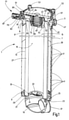
- the filter housing 1 has a filter head 3 on which flange parts 5 are located on the outside.
- the filter housing 1 can be attached to the edge of an upper wall opening of a storage container or tank (not shown) in such a way that a filter bowl 7, which adjoins the lower end of the filter head 3, extends vertically inside the tank.
- the length of the in 1 and 2 Shortened shown filter bowl 7 dimensioned such that the lower end 9 of the filter bowl 7 is below the lowest fluid level to be expected during operation, such as hydraulic oil.
- the filter bowl 7 in the example shown is fixed in the form of a relatively thin-walled circular cylinder on the filter head 3 by a flange 11 . It goes without saying that the invention can advantageously be used not only with in-tank filter devices, but equally also with other types of filter devices.
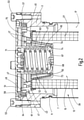
- a filter element 13 which can be exchanged and accommodated in the housing 1, can be flown through from its inner side 15, which forms the unfiltrate side, to its outer side 17, which forms the filtrate side, there is an inflow housing 19 at the lower end 9 of the filter bowl 7
- the filter element 13 has an end cap 29 which engages in the opening 21 of the inflow housing 19 with an annular body 31 at the end.
- a flapper valve 33 located at the central passage 35 of the end cap 29 opens to the flow of fluid flowing from the inlet port 27 of the inflow housing 19 to the inside 15 of the filter element 13 .
- the filter material 27 is supported against the flow forces by an outer casing 39 which has a perforation, for example in the form of a hole, and forms a type of outer support tube.
- a lattice structure or the like could also be provided.
- window openings 41 are formed in the filter bowl.
- the window openings correspond to the state of the art that is usual for in-tank filters 41 is not arranged over the entire length of the filter bowl 7, but only in selected areas.
- the window openings 41 according to the relevant EP 2 249 941 B1 mediated teaching be arranged in adaptation to the operational fluid level of the tank such that any gas bubbles located in the cleaned fluid can be separated and / or collected for a release.
- the filter element 13 has on its upper side, which faces a housing cover part 51 which can be detachably attached to the filter head 3 by means of screws 53, a specially designed element cap 43 which is injection molded from a plastic material.
- a specially designed element cap 43 which is injection molded from a plastic material.
- the element cap 43 has a receiving part 45 in the form of a flat circular ring which, as is usual with filter element end caps, forms a border for the facing end of the filter material 27 .
- the outer circumference of the receiving part 45 is surrounded by a ring of evenly distributed, plate-like webs 47, the planes of which extend in the radial direction and which form the supports for an annular receiving crown 49, which is at an axial distance from the receiving part 45 and at a radial distance from the outside of the rest of the filter element 13 is located.
- a guide part 52 connects to its inner circumference, which has the shape of a hollow cone, which extends axially with its tapered end 54 into the inner side 15 of the filter element 13 and at the lower edge in a radially inwardly projecting manner Rib 55 ends.
- the webs 47 continue below the receiving part 45 along the inside of the guide part 52 as a further ring of webs 47, which protrude radially inward and extend from the underside of the receiving part 45 to the rib 55 at the lower end 54 of the guide part 52.
- the peripheral edge of the receiving crown 49 is encompassed by a shaped seal 57, which has a U-shaped cross section and forms the seal with the cover part 51 with its upper profile leg 59, while the lower profile leg 61 and that between the legs 59 and 61 running profile web 64 form the seal against the filter bowl 7.
- the molded seal 57 therefore seals the entire fluid system located above the tank wall from the environment.
- a guide wall 63 which, in the form of a circular cylinder, projects coaxially into the inside of the hollow cone formed by the guide part 52 of the element cap 43 .
- the guide wall 63 forms a type of valve housing in which the valve closing member of the bypass valve device is guided in a displaceable manner.
- This valve closure member is formed by a hollow cylinder 65, the cavity of which is closed at one end by a bottom 67 on which a compression spring 69 placed in the cavity bears, the other end of which is centered on a pin 71 projecting axially from the cover part 51.
- the hollow cylinder 65 forming the valve closing member which is pushed into the in 2 is prestressed in the closed position shown, forms a circumferential contact bevel on the outside at the end closed by the base 67, which forms a valve cone 73 which, under the influence of the compression spring 69, is in sealing contact with the valve seat part during normal filtration operation, which is defined by a sealing edge 74 on the inner edge of the rib 55 of the guide part 52 is formed.
- the element cap 43 which is designed in one piece including the receiving part 45, the webs 47, the receiving crown 49 and the guide part 52, is completed by a holding bracket 75, which is anchored in a hinged manner on the rim of the webs 47 and makes it possible to handle the filter element 13 when and expansion easier. Furthermore, there is a differential pressure measuring device 77 which, due to the pressure drop occurring on the filter material 27 during filtration, provides an indication of the operating state of the filter element 13 .
- the measuring device 77 has a measuring housing 79 which is screwed into the wall of the filter head 3 in a connection area 81 .
- the measuring housing 79 there is a spring-loaded measuring piston 82, one end of which is acted upon by the instantaneous pressure of the unfiltrate side and the other end of which is acted upon by the instantaneous pressure of the filtrate side.
- the measuring housing 79 has a passage 83 at the end adjoining the outside (filtrate side).
- the pressure from the unfiltrate side reaches the measuring housing 79 via a duct from the inside 15, which has a vertical duct section 84 on the element cap 43, which runs along a web 47, and a horizontal duct section 85, which leads to a channel formed between the cover part 51 and the filter head 3 Room 89 leads, from where it enters the measuring housing 79 via a wall opening.
- an evaluation unit 87 is connected to the outer end of the measuring housing 79, which, for example, supplies an optical signal.
- the receiving crown 49 is designed as a component which is preferably part of the filter element as a whole. Because said component 49 is designed as a coherent component up to the sealing edge 55, the same opening pressure always occurs at the bypass valve despite any manufacturing tolerances that may exist on the filter element itself or on other components is a major advantage over other solutions. Otherwise, the receiving housing for the bypass valve can also be designed in several parts, apart from the area mentioned above.
Landscapes
- Chemical & Material Sciences (AREA)
- Chemical Kinetics & Catalysis (AREA)
- Filtration Of Liquid (AREA)
Claims (11)
- Dispositif de filtration, comprenant une tête (3) de filtre, une enveloppe (1) de filtre ayant un pot (7) de filtre et une partie (51) de couvercle d'enveloppe, qui peut être retirée, l'enveloppe (1) recevant un élément (13) filtrant, qui sépare un côté (15) de non filtrat d'un côté (17) de filtrat, et comprenant un dispositif de soupape de dérivation, qui a un élément (65) de fermeture de la soupape, qui est précontraint par un ressort (69) de fermeture dans une position de fermeture s'appliquant à une partie (74) formant siège de soupape et qui, lorsque l'élément (13) filtrant est bloqué, vient dans une position, dans laquelle, en contournant l'élément (13) filtrant, il dégage un trajet de fluide du côté (15) de non filtrat ou du côté (17) de filtrat, dans lequel l'élément (65) de fermeture de la soupape et le ressort (69) de fermeture sont montés sur la partie (51) formant couvercle et la partie (74) formant siège de la soupape se trouve sur une coiffe (43) de l'élément (13) filtrant, coiffe qui a une partie (45) de réception formant une bordure pour l'extrémité, tournée vers la partie (51) formant couvercle, de la matière (27) filtrante de l'élément (13) filtrant, caractérisé en ce qu'une couronne composée d'entretoises (47) réparties d'une manière uniforme entoure le pourtour extérieur de la partie (45) de réception en forme d'anneau de cercle de la coiffe (43) de l'élément, ces entretoises étant formées à la manière de plaques et s'étendant par leurs plans dans la direction radiale et qui forment des supports d'un couronnement (49) de réception en forme d'anneau de cercle, qui se trouve à distance axiale de la partie (45) de réception ainsi qu'à distance radiale du côté extérieur du reste de l'élément (13) filtrant.
- Dispositif de filtration suivant la revendication 1, caractérisé en ce que l'élément (65) de fermeture de la soupape est formé d'un cylindre creux, dont la cavité est fermée à une extrémité par un fond (67), sur lequel s'appuie l'une des extrémités d'un ressort (69) de compression se trouvant dans la cavité, tandis que l'autre extrémité s'appuie sur la partie (51) formant couvercle.
- Dispositif de filtration suivant la revendication 2, caractérisé en ce que la partie (51) formant couvercle a, faisant saillie dans la direction de l'élément (13) filtrant, une paroi (63) de guidage de constitution cylindrique de section droite circulaire, le long de laquelle le cylindre creux de l'élément (65) de fermeture de la soupape est guidé par sa paroi extérieure.
- Dispositif de filtration suivant la revendication 2 ou 3, caractérisé en ce que le cylindre creux de l'élément (65) de fermeture de la soupape a, à l'extrémité fermée par le fond (67) du côté extérieur, un biseau de contact faisant le tour, qui forme un cône (73) de la soupape qui, sous l'influence du ressort (69) de compression dans le fonctionnement normal de filtration, est maintenu en contact étanche avec la partie (74) formant siège de la soupape de la coiffe (43) de l'élément.
- Dispositif de filtration suivant l'une des revendications précédentes, caractérisé en ce que la coiffe (43) de l'élément (13) filtrant a, sur la bordure de l'extrémité de la matière (27) filtrante, une partie (45) de réception sous la forme d'un anneau de cercle à surface plane, au pourtour intérieur duquel se raccorde une partie (52) de guidage, qui s'étend axialement dans le côté (15) intérieur, formant le côté de non filtrat, de l'élément (13) filtrant et sur laquelle est formée la partie (74) formant siège de la soupape.
- Dispositif de filtration suivant l'une des revendications précédentes, caractérisé en ce que la partie (52) de guidage possède la forme d'un cône creux, qui s'étend par son extrémité (54) ayant une ouverture dans le côté (15) intérieur de l'élément (13) filtrant et qui forme, au bord (55) de son ouverture, l'arête (74) d'étanchéité de l'élément de fermeture de la soupape.
- Dispositif de filtration suivant la revendication 6, caractérisé en ce que le cône creux de la partie (52) de guidage a, du côté du pourtour extérieur, des entretoises (47) de guidage en saillie d'une couronne.
- Dispositif de filtration suivant l'une des revendications précédentes, caractérisé en ce que l'autre couronne en entretoises (47) réparties de manière uniforme, qui sont formées à la manière plaques en tant que prolongement des entretoises (47) se trouvant dans le cône (65) creux, entoure le pourtour extérieur de la partie (45) de réception en forme d'anneau de cercle de la coiffe (43) de l'élément.
- Dispositif de filtration suivant l'une des revendications précédentes, caractérisé en ce que le couronnement (49) de réception est entouré sur son pourtour extérieur d'un joint (57) moulé, qui a une section transversale profilée en forme de U, dont une branche (59) du profil forme l'étanchéité contre la partie (51) formant couvercle et son entretoise (64) profilée et dont l'autre branche (61) du profil forme l'étanchéité entre le couronnement (49) de réception et la tête (3) du filtre.
- Dispositif de filtration suivant la revendication 7 à 9, caractérisé en ce que la partie (45) de réception, les entretoises (47), le couronnement (49) de réception et la partie (52) de guidage, reliés entre eux, constituent la coiffe (43) de l'élément.
- Dispositif de filtration suivant l'une des revendications précédentes, caractérisé en ce qu'il y a un dispositif (77) de mesure de la différence de pression, qui est complété de préférence par une unité (87) optique d'analyse.
Applications Claiming Priority (4)
| Application Number | Priority Date | Filing Date | Title |
|---|---|---|---|
| DE102015003606.8A DE102015003606A1 (de) | 2015-03-19 | 2015-03-19 | Filtervorrichtung |
| DE102015003604.1A DE102015003604A1 (de) | 2015-03-19 | 2015-03-19 | Filtervorrichtung |
| PCT/EP2016/000042 WO2016146226A1 (fr) | 2015-03-19 | 2016-01-12 | Dispositif filtrant |
| EP16700320.1A EP3271043B1 (fr) | 2015-03-19 | 2016-01-12 | Dispositif filtrant |
Related Parent Applications (3)
| Application Number | Title | Priority Date | Filing Date |
|---|---|---|---|
| PCT/EP2016/000042 Previously-Filed-Application WO2016146226A1 (fr) | 2015-03-19 | 2016-01-12 | Dispositif filtrant |
| EP16700320.1A Division EP3271043B1 (fr) | 2015-03-19 | 2016-01-12 | Dispositif filtrant |
| EP16700320.1A Division-Into EP3271043B1 (fr) | 2015-03-19 | 2016-01-12 | Dispositif filtrant |
Publications (2)
| Publication Number | Publication Date |
|---|---|
| EP3736033A1 EP3736033A1 (fr) | 2020-11-11 |
| EP3736033B1 true EP3736033B1 (fr) | 2022-03-23 |
Family
ID=55085642
Family Applications (3)
| Application Number | Title | Priority Date | Filing Date |
|---|---|---|---|
| EP16700320.1A Active EP3271043B1 (fr) | 2015-03-19 | 2016-01-12 | Dispositif filtrant |
| EP16700321.9A Active EP3271042B1 (fr) | 2015-03-19 | 2016-01-12 | Dispositif filtre |
| EP20176555.9A Active EP3736033B1 (fr) | 2015-03-19 | 2016-01-12 | Dispositif filtrant |
Family Applications Before (2)
| Application Number | Title | Priority Date | Filing Date |
|---|---|---|---|
| EP16700320.1A Active EP3271043B1 (fr) | 2015-03-19 | 2016-01-12 | Dispositif filtrant |
| EP16700321.9A Active EP3271042B1 (fr) | 2015-03-19 | 2016-01-12 | Dispositif filtre |
Country Status (5)
| Country | Link |
|---|---|
| US (2) | US10150064B2 (fr) |
| EP (3) | EP3271043B1 (fr) |
| JP (2) | JP6669772B2 (fr) |
| CN (2) | CN107530600B (fr) |
| WO (2) | WO2016146227A1 (fr) |
Families Citing this family (14)
| Publication number | Priority date | Publication date | Assignee | Title |
|---|---|---|---|---|
| DE102017003489A1 (de) * | 2017-04-11 | 2018-10-11 | Rt-Filtertechnik Gmbh | Filtervorrichtung |
| JP7085821B2 (ja) * | 2017-11-17 | 2022-06-17 | ヤマシンフィルタ株式会社 | フィルタ装置 |
| DE102017012018A1 (de) * | 2017-12-22 | 2019-06-27 | Mann+Hummel Gmbh | Filtersystem mit Rückschlagventil und Filterelement |
| DE102018204255A1 (de) * | 2018-03-20 | 2019-09-26 | Mahle International Gmbh | Filtereinrichtung |
| JP6797149B2 (ja) * | 2018-04-25 | 2020-12-09 | ヤマシンフィルタ株式会社 | ストレーナ |
| CN112118898B (zh) * | 2018-06-07 | 2023-05-30 | 雅玛信过滤器株式会社 | 过滤器装置 |
| CN109296483B (zh) * | 2018-11-08 | 2024-01-05 | 河北亿利科技股份有限公司 | 一种燃油预滤器滤芯总成 |
| JP6983744B2 (ja) * | 2018-11-16 | 2021-12-17 | ヤマシンフィルタ株式会社 | 差圧検出装置 |
| JP7250603B2 (ja) * | 2019-04-23 | 2023-04-03 | ヤマシンフィルタ株式会社 | フィルタエレメント及びフィルタ装置 |
| CN109882326B (zh) * | 2019-04-30 | 2024-04-05 | 无锡亿利环保科技有限公司 | 具有安全阀的燃油滤芯 |
| CN111765023A (zh) * | 2020-07-08 | 2020-10-13 | 岑道美 | 一种高耐久的汽车燃油滤清器 |
| US20220401859A1 (en) * | 2021-06-18 | 2022-12-22 | Pratt & Whitney Canada Corp. | Impending bypass switch with magnetic sensor |
| CN116006550B (zh) * | 2023-03-22 | 2023-07-07 | 南京讯联液压技术股份有限公司 | 一种免维护的液压过滤装置及其控制系统 |
| CN116292528B (zh) * | 2023-03-27 | 2023-09-08 | 徐州中液过滤技术有限公司 | 一种油箱安装自封型回油过滤器 |
Family Cites Families (15)
| Publication number | Priority date | Publication date | Assignee | Title |
|---|---|---|---|---|
| US3070232A (en) * | 1959-10-01 | 1962-12-25 | Purolator Products Inc | Filter unit with signal device |
| US3344923A (en) * | 1964-03-02 | 1967-10-03 | Pall Corp | Filter unit having filter elements in series and in reserve |
| US3794168A (en) * | 1972-07-31 | 1974-02-26 | Parker Hannifin Corp | Filter with condition indicator |
| US4654140A (en) * | 1985-11-18 | 1987-03-31 | Chen Yen Ming | Pressure indicating device for indicating clogging condition of a filter |
| EP1781395A4 (fr) * | 2004-07-12 | 2008-10-01 | Schroeder Ind Llc | Element filtrant remplacable possedant un piege annulaire solidaire |
| DE102005043752B3 (de) | 2005-09-13 | 2007-05-10 | Frank Suchy | Differenzdruckmanometer |
| DE102007056362A1 (de) | 2007-11-22 | 2009-05-28 | Hydac Filtertechnik Gmbh | Filtervorrichtung, insbesondere Rücklauf-Saugfilter, sowie Filterelement für eine solche Filtervorrichtung |
| DE102008012521A1 (de) * | 2008-03-04 | 2009-09-17 | Rt-Filtertechnik Gmbh | Filtervorrichtung sowie Filterelement für eine dahingehende Filtervorrichtung |
| DE102008059146A1 (de) * | 2008-11-26 | 2010-06-10 | Hydac Filtertechnik Gmbh | Filtervorrichtung und Filterelement |
| JP5368079B2 (ja) * | 2008-12-24 | 2013-12-18 | 和興フィルタテクノロジー株式会社 | オイルフィルタ |
| DE102010049975A1 (de) * | 2010-10-18 | 2012-04-19 | Hydac Filtertechnik Gmbh | Filtervorrichtung |
| DE102010063822A1 (de) * | 2010-12-22 | 2012-06-28 | Hengst Gmbh & Co. Kg | Flüssigkeitsfilter mit einem Filterumgehungsventil |
| FR2969734B1 (fr) * | 2010-12-23 | 2014-01-17 | Mecaplast Sa | Dispositif de commande du debit d'un fluide de refroidissement |
| US8986539B2 (en) * | 2011-04-19 | 2015-03-24 | Cummins Filtration Ip Inc. | Inside-out flow filter with pressure recovery |
| DE102013210065A1 (de) * | 2013-05-29 | 2014-12-04 | Mahle International Gmbh | Filtereinrichtung, insbesondere für ein Kraftfahrzeug |
-
2016
- 2016-01-12 CN CN201680016626.9A patent/CN107530600B/zh active Active
- 2016-01-12 US US15/557,514 patent/US10150064B2/en active Active
- 2016-01-12 EP EP16700320.1A patent/EP3271043B1/fr active Active
- 2016-01-12 EP EP16700321.9A patent/EP3271042B1/fr active Active
- 2016-01-12 US US15/557,860 patent/US10188969B2/en active Active
- 2016-01-12 JP JP2017549193A patent/JP6669772B2/ja active Active
- 2016-01-12 CN CN201680016740.1A patent/CN107405547B/zh active Active
- 2016-01-12 EP EP20176555.9A patent/EP3736033B1/fr active Active
- 2016-01-12 WO PCT/EP2016/000043 patent/WO2016146227A1/fr active Application Filing
- 2016-01-12 JP JP2017548842A patent/JP6756730B2/ja active Active
- 2016-01-12 WO PCT/EP2016/000042 patent/WO2016146226A1/fr active Application Filing
Also Published As
| Publication number | Publication date |
|---|---|
| US20180050285A1 (en) | 2018-02-22 |
| JP6669772B2 (ja) | 2020-03-18 |
| US10150064B2 (en) | 2018-12-11 |
| CN107530600B (zh) | 2020-12-25 |
| WO2016146226A1 (fr) | 2016-09-22 |
| EP3271043B1 (fr) | 2020-09-23 |
| EP3271043A1 (fr) | 2018-01-24 |
| JP2018512997A (ja) | 2018-05-24 |
| US20180050286A1 (en) | 2018-02-22 |
| CN107405547B (zh) | 2020-02-21 |
| CN107405547A (zh) | 2017-11-28 |
| US10188969B2 (en) | 2019-01-29 |
| JP6756730B2 (ja) | 2020-09-16 |
| JP2018511465A (ja) | 2018-04-26 |
| CN107530600A (zh) | 2018-01-02 |
| EP3271042B1 (fr) | 2021-04-14 |
| WO2016146227A1 (fr) | 2016-09-22 |
| EP3271042A1 (fr) | 2018-01-24 |
| EP3736033A1 (fr) | 2020-11-11 |
Similar Documents
| Publication | Publication Date | Title |
|---|---|---|
| EP3736033B1 (fr) | Dispositif filtrant | |
| EP2682172B1 (fr) | Reservoir de liquide avec un dispositif de filtration | |
| DE102006039826B4 (de) | Filtervorrichtung, Filterelement sowie Verfahren zum Betrieb der Filtervorrichtung | |
| EP2046473B1 (fr) | Dispositif de filtration | |
| DE102017001968A1 (de) | Filtervorrichtung | |
| DE102013012918B4 (de) | Flüssigkeitsfilter und Filterelement, insbesondere für Kraftstoff | |
| EP2105184B1 (fr) | Filtre | |
| DE102014000281A1 (de) | Becherförmiges Gehäuse, Vorrichtung zum Abscheiden von Flüssigkeit aus Luft sowie Verfahren zur Montage des becherförmigen Gehäuses auf einen Nippel | |
| EP3641909B1 (fr) | Systeme de filtration avec elemente filtrant et elemente secondaire pour fermer un conduit central | |
| DE102015003604A1 (de) | Filtervorrichtung | |
| DE202009013661U1 (de) | Filteranordnung | |
| DE102009031358A1 (de) | Filtervorrichtung und Filterelementanordnung zur Anwendung in der Filtervorrichtung | |
| DE102007046208A1 (de) | Filtervorrichtung und Filterelement | |
| DE202007011096U1 (de) | Filterelement, Filtergehäuse und Filteranordnung | |
| DE102013012917A1 (de) | Flüssigkeitsfilter, insbesondere für Kraftstoff | |
| WO2008092559A1 (fr) | Élément filtrant destiné à la purification de liquides | |
| DE102009048588A1 (de) | Filtereinrichtung, insbesondere zur Flüssigkeitsfilterung in Brennkraftmaschinen | |
| EP2910290A1 (fr) | Filtre à liquide | |
| DE102007014813A1 (de) | Filtervorrichtung | |
| DE102015003606A1 (de) | Filtervorrichtung | |
| DE102012007627B4 (de) | Filterelement | |
| EP1419807B1 (fr) | Dispositif de filtration avec cartouche filtrante remplaçable | |
| DE3423274C2 (de) | Filter für Flüssigkeiten | |
| DE102013004865A1 (de) | Filtereinrichtung mit einem ringförmigen Filterelement | |
| EP2826534A1 (fr) | Dispositif de filtre |
Legal Events
| Date | Code | Title | Description |
|---|---|---|---|
| PUAI | Public reference made under article 153(3) epc to a published international application that has entered the european phase |
Free format text: ORIGINAL CODE: 0009012 |
|
| STAA | Information on the status of an ep patent application or granted ep patent |
Free format text: STATUS: THE APPLICATION HAS BEEN PUBLISHED |
|
| AC | Divisional application: reference to earlier application |
Ref document number: 3271043 Country of ref document: EP Kind code of ref document: P |
|
| AK | Designated contracting states |
Kind code of ref document: A1 Designated state(s): AL AT BE BG CH CY CZ DE DK EE ES FI FR GB GR HR HU IE IS IT LI LT LU LV MC MK MT NL NO PL PT RO RS SE SI SK SM TR |
|
| STAA | Information on the status of an ep patent application or granted ep patent |
Free format text: STATUS: REQUEST FOR EXAMINATION WAS MADE |
|
| 17P | Request for examination filed |
Effective date: 20210511 |
|
| RBV | Designated contracting states (corrected) |
Designated state(s): AL AT BE BG CH CY CZ DE DK EE ES FI FR GB GR HR HU IE IS IT LI LT LU LV MC MK MT NL NO PL PT RO RS SE SI SK SM TR |
|
| STAA | Information on the status of an ep patent application or granted ep patent |
Free format text: STATUS: EXAMINATION IS IN PROGRESS |
|
| 17Q | First examination report despatched |
Effective date: 20210715 |
|
| RAP3 | Party data changed (applicant data changed or rights of an application transferred) |
Owner name: HYDAC FILTERTECHNIK GMBH |
|
| GRAP | Despatch of communication of intention to grant a patent |
Free format text: ORIGINAL CODE: EPIDOSNIGR1 |
|
| STAA | Information on the status of an ep patent application or granted ep patent |
Free format text: STATUS: GRANT OF PATENT IS INTENDED |
|
| INTG | Intention to grant announced |
Effective date: 20211221 |
|
| GRAS | Grant fee paid |
Free format text: ORIGINAL CODE: EPIDOSNIGR3 |
|
| GRAA | (expected) grant |
Free format text: ORIGINAL CODE: 0009210 |
|
| STAA | Information on the status of an ep patent application or granted ep patent |
Free format text: STATUS: THE PATENT HAS BEEN GRANTED |
|
| AC | Divisional application: reference to earlier application |
Ref document number: 3271043 Country of ref document: EP Kind code of ref document: P |
|
| AK | Designated contracting states |
Kind code of ref document: B1 Designated state(s): AL AT BE BG CH CY CZ DE DK EE ES FI FR GB GR HR HU IE IS IT LI LT LU LV MC MK MT NL NO PL PT RO RS SE SI SK SM TR |
|
| REG | Reference to a national code |
Ref country code: GB Ref legal event code: FG4D Free format text: NOT ENGLISH |
|
| REG | Reference to a national code |
Ref country code: CH Ref legal event code: EP |
|
| REG | Reference to a national code |
Ref country code: IE Ref legal event code: FG4D Free format text: LANGUAGE OF EP DOCUMENT: GERMAN |
|
| REG | Reference to a national code |
Ref country code: DE Ref legal event code: R096 Ref document number: 502016014685 Country of ref document: DE |
|
| REG | Reference to a national code |
Ref country code: AT Ref legal event code: REF Ref document number: 1477051 Country of ref document: AT Kind code of ref document: T Effective date: 20220415 |
|
| REG | Reference to a national code |
Ref country code: LT Ref legal event code: MG9D |
|
| REG | Reference to a national code |
Ref country code: NL Ref legal event code: MP Effective date: 20220323 |
|
| PG25 | Lapsed in a contracting state [announced via postgrant information from national office to epo] |
Ref country code: SE Free format text: LAPSE BECAUSE OF FAILURE TO SUBMIT A TRANSLATION OF THE DESCRIPTION OR TO PAY THE FEE WITHIN THE PRESCRIBED TIME-LIMIT Effective date: 20220323 Ref country code: RS Free format text: LAPSE BECAUSE OF FAILURE TO SUBMIT A TRANSLATION OF THE DESCRIPTION OR TO PAY THE FEE WITHIN THE PRESCRIBED TIME-LIMIT Effective date: 20220323 Ref country code: NO Free format text: LAPSE BECAUSE OF FAILURE TO SUBMIT A TRANSLATION OF THE DESCRIPTION OR TO PAY THE FEE WITHIN THE PRESCRIBED TIME-LIMIT Effective date: 20220623 Ref country code: LT Free format text: LAPSE BECAUSE OF FAILURE TO SUBMIT A TRANSLATION OF THE DESCRIPTION OR TO PAY THE FEE WITHIN THE PRESCRIBED TIME-LIMIT Effective date: 20220323 Ref country code: HR Free format text: LAPSE BECAUSE OF FAILURE TO SUBMIT A TRANSLATION OF THE DESCRIPTION OR TO PAY THE FEE WITHIN THE PRESCRIBED TIME-LIMIT Effective date: 20220323 Ref country code: BG Free format text: LAPSE BECAUSE OF FAILURE TO SUBMIT A TRANSLATION OF THE DESCRIPTION OR TO PAY THE FEE WITHIN THE PRESCRIBED TIME-LIMIT Effective date: 20220623 |
|
| PG25 | Lapsed in a contracting state [announced via postgrant information from national office to epo] |
Ref country code: LV Free format text: LAPSE BECAUSE OF FAILURE TO SUBMIT A TRANSLATION OF THE DESCRIPTION OR TO PAY THE FEE WITHIN THE PRESCRIBED TIME-LIMIT Effective date: 20220323 Ref country code: GR Free format text: LAPSE BECAUSE OF FAILURE TO SUBMIT A TRANSLATION OF THE DESCRIPTION OR TO PAY THE FEE WITHIN THE PRESCRIBED TIME-LIMIT Effective date: 20220624 Ref country code: FI Free format text: LAPSE BECAUSE OF FAILURE TO SUBMIT A TRANSLATION OF THE DESCRIPTION OR TO PAY THE FEE WITHIN THE PRESCRIBED TIME-LIMIT Effective date: 20220323 |
|
| PG25 | Lapsed in a contracting state [announced via postgrant information from national office to epo] |
Ref country code: NL Free format text: LAPSE BECAUSE OF FAILURE TO SUBMIT A TRANSLATION OF THE DESCRIPTION OR TO PAY THE FEE WITHIN THE PRESCRIBED TIME-LIMIT Effective date: 20220323 |
|
| PG25 | Lapsed in a contracting state [announced via postgrant information from national office to epo] |
Ref country code: SM Free format text: LAPSE BECAUSE OF FAILURE TO SUBMIT A TRANSLATION OF THE DESCRIPTION OR TO PAY THE FEE WITHIN THE PRESCRIBED TIME-LIMIT Effective date: 20220323 Ref country code: SK Free format text: LAPSE BECAUSE OF FAILURE TO SUBMIT A TRANSLATION OF THE DESCRIPTION OR TO PAY THE FEE WITHIN THE PRESCRIBED TIME-LIMIT Effective date: 20220323 Ref country code: RO Free format text: LAPSE BECAUSE OF FAILURE TO SUBMIT A TRANSLATION OF THE DESCRIPTION OR TO PAY THE FEE WITHIN THE PRESCRIBED TIME-LIMIT Effective date: 20220323 Ref country code: PT Free format text: LAPSE BECAUSE OF FAILURE TO SUBMIT A TRANSLATION OF THE DESCRIPTION OR TO PAY THE FEE WITHIN THE PRESCRIBED TIME-LIMIT Effective date: 20220725 Ref country code: ES Free format text: LAPSE BECAUSE OF FAILURE TO SUBMIT A TRANSLATION OF THE DESCRIPTION OR TO PAY THE FEE WITHIN THE PRESCRIBED TIME-LIMIT Effective date: 20220323 Ref country code: EE Free format text: LAPSE BECAUSE OF FAILURE TO SUBMIT A TRANSLATION OF THE DESCRIPTION OR TO PAY THE FEE WITHIN THE PRESCRIBED TIME-LIMIT Effective date: 20220323 Ref country code: CZ Free format text: LAPSE BECAUSE OF FAILURE TO SUBMIT A TRANSLATION OF THE DESCRIPTION OR TO PAY THE FEE WITHIN THE PRESCRIBED TIME-LIMIT Effective date: 20220323 |
|
| PG25 | Lapsed in a contracting state [announced via postgrant information from national office to epo] |
Ref country code: PL Free format text: LAPSE BECAUSE OF FAILURE TO SUBMIT A TRANSLATION OF THE DESCRIPTION OR TO PAY THE FEE WITHIN THE PRESCRIBED TIME-LIMIT Effective date: 20220323 Ref country code: IS Free format text: LAPSE BECAUSE OF FAILURE TO SUBMIT A TRANSLATION OF THE DESCRIPTION OR TO PAY THE FEE WITHIN THE PRESCRIBED TIME-LIMIT Effective date: 20220723 Ref country code: AL Free format text: LAPSE BECAUSE OF FAILURE TO SUBMIT A TRANSLATION OF THE DESCRIPTION OR TO PAY THE FEE WITHIN THE PRESCRIBED TIME-LIMIT Effective date: 20220323 |
|
| REG | Reference to a national code |
Ref country code: DE Ref legal event code: R097 Ref document number: 502016014685 Country of ref document: DE |
|
| PLBE | No opposition filed within time limit |
Free format text: ORIGINAL CODE: 0009261 |
|
| STAA | Information on the status of an ep patent application or granted ep patent |
Free format text: STATUS: NO OPPOSITION FILED WITHIN TIME LIMIT |
|
| PG25 | Lapsed in a contracting state [announced via postgrant information from national office to epo] |
Ref country code: DK Free format text: LAPSE BECAUSE OF FAILURE TO SUBMIT A TRANSLATION OF THE DESCRIPTION OR TO PAY THE FEE WITHIN THE PRESCRIBED TIME-LIMIT Effective date: 20220323 |
|
| 26N | No opposition filed |
Effective date: 20230102 |
|
| PG25 | Lapsed in a contracting state [announced via postgrant information from national office to epo] |
Ref country code: SI Free format text: LAPSE BECAUSE OF FAILURE TO SUBMIT A TRANSLATION OF THE DESCRIPTION OR TO PAY THE FEE WITHIN THE PRESCRIBED TIME-LIMIT Effective date: 20220323 |
|
| REG | Reference to a national code |
Ref country code: CH Ref legal event code: PL |
|
| PG25 | Lapsed in a contracting state [announced via postgrant information from national office to epo] |
Ref country code: LU Free format text: LAPSE BECAUSE OF NON-PAYMENT OF DUE FEES Effective date: 20230112 |
|
| REG | Reference to a national code |
Ref country code: BE Ref legal event code: MM Effective date: 20230131 |
|
| PG25 | Lapsed in a contracting state [announced via postgrant information from national office to epo] |
Ref country code: LI Free format text: LAPSE BECAUSE OF NON-PAYMENT OF DUE FEES Effective date: 20230131 Ref country code: CH Free format text: LAPSE BECAUSE OF NON-PAYMENT OF DUE FEES Effective date: 20230131 |
|
| PG25 | Lapsed in a contracting state [announced via postgrant information from national office to epo] |
Ref country code: BE Free format text: LAPSE BECAUSE OF NON-PAYMENT OF DUE FEES Effective date: 20230131 |
|
| PGFP | Annual fee paid to national office [announced via postgrant information from national office to epo] |
Ref country code: GB Payment date: 20231101 Year of fee payment: 9 |
|
| PG25 | Lapsed in a contracting state [announced via postgrant information from national office to epo] |
Ref country code: IE Free format text: LAPSE BECAUSE OF NON-PAYMENT OF DUE FEES Effective date: 20230112 |
|
| PGFP | Annual fee paid to national office [announced via postgrant information from national office to epo] |
Ref country code: FR Payment date: 20231127 Year of fee payment: 9 |
|
| REG | Reference to a national code |
Ref country code: AT Ref legal event code: MM01 Ref document number: 1477051 Country of ref document: AT Kind code of ref document: T Effective date: 20230112 |
|
| PG25 | Lapsed in a contracting state [announced via postgrant information from national office to epo] |
Ref country code: AT Free format text: LAPSE BECAUSE OF NON-PAYMENT OF DUE FEES Effective date: 20230112 |
|
| PG25 | Lapsed in a contracting state [announced via postgrant information from national office to epo] |
Ref country code: AT Free format text: LAPSE BECAUSE OF NON-PAYMENT OF DUE FEES Effective date: 20230112 |
|
| PGFP | Annual fee paid to national office [announced via postgrant information from national office to epo] |
Ref country code: DE Payment date: 20240131 Year of fee payment: 9 |
|
| PGFP | Annual fee paid to national office [announced via postgrant information from national office to epo] |
Ref country code: IT Payment date: 20240110 Year of fee payment: 9 |
|
| PG25 | Lapsed in a contracting state [announced via postgrant information from national office to epo] |
Ref country code: MC Free format text: LAPSE BECAUSE OF FAILURE TO SUBMIT A TRANSLATION OF THE DESCRIPTION OR TO PAY THE FEE WITHIN THE PRESCRIBED TIME-LIMIT Effective date: 20220323 |
|
| PG25 | Lapsed in a contracting state [announced via postgrant information from national office to epo] |
Ref country code: MC Free format text: LAPSE BECAUSE OF FAILURE TO SUBMIT A TRANSLATION OF THE DESCRIPTION OR TO PAY THE FEE WITHIN THE PRESCRIBED TIME-LIMIT Effective date: 20220323 |